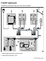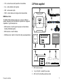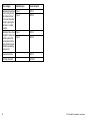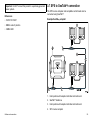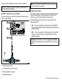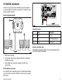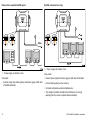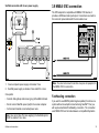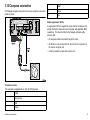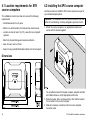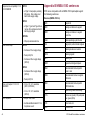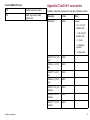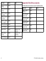
1
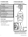
Trademarks and registered trademarks
Autohelm, hsb2, RayTech Navigator, Sail Pilot, SeaTalk, SeaTalkNG, SeaTalkHS and Sportpilot are registered trademarks of Raymarine
UK Limited. RayTalk, Seahawk, Smartpilot, Pathfinder and Raymarine are registered trademarks of Raymarine Holdings Limited.
All other product names are trademarks or registered trademarks of their respective owners.
Fair Use Statement
You may print no more than three copies of this manual for your own use. You may not make any further copies or distribute or use the
manual in any other way including without limitation exploiting the manual commercially or giving or selling copies to third parties.
Copyright ©2010 Raymarine UK Ltd. All rights reserved.
ENGLISH
Document number: 87072-3
Date: 07 2010
Contents
Chapter 1 Introduction ............................................. 7
Handbook information ..................................................... 7
Important information ...................................................... 8
Chapter 2 Planning the installation ........................ 11
2.1 Installation checklist .................................................. 12
3.12 Sleep switch connection .......................................... 36
Chapter 4 Installation ............................................... 37
4.1 Location requirements for SPX course
computers ...................................................................... 38
4.2 Installing the SPX course computer ............................ 38
2.2 Inboard autopilot system............................................ 12
4.3 Initial checks for the autopilot installation .................... 39
2.3 SeaTalkng autopilot system......................................... 14
2.4 SeaTalk autopilot system ........................................... 16
Chapter 5 Maintenance and support ...................... 41
2.5 Parts supplied........................................................... 17
2.6 Required additional components ................................ 18
5.2 Cleaning................................................................... 42
Chapter 3 Cables and connections......................... 21
Appendix A Technical specification ....................... 45
5.1 Service and maintenance .......................................... 42
5.3 Raymarine customer support ..................................... 43
3.1 General cabling guidance .......................................... 22
3.2 SPX-10 / SPX-30 connections overview ..................... 23
3.3 SPX-SOL connections overview................................. 23
Appendix B NMEA 0183 sentences ........................ 46
3.4 Power and drive cables ............................................. 24
3.5 Fuses and circuit protection ....................................... 27
Appendix C SeaTalkng accessories......................... 47
3.6 Grounding ................................................................ 28
Appendix D SeaTalk accessories............................ 48
3.7 SPX to SeaTalkng connection ..................................... 29
3.8 SeaTalk connection ................................................... 31
3.9 NMEA 0183 connection ............................................. 33
3.10 Compass connection ............................................... 35
3.11 Rudder reference connection ................................... 36
5
6
SPX SmartPilot installation instructions
Chapter 1: Introduction
SPX handbooks
SPX documentation
Handbook information
Description
Part number
This handbook describes installation of SPX course computers as
part of a SmartPilot autopilot system.
SPX-10, SPX-30, SPX-SOL Installation instructions
Plan and install a SmartPilot system including an SPX
course computer.
87072
SPX-CAN Installation instructions
Plan and install a SmartPilot system including an SPX
course computer.
87073
SPX-DIO Installation instructions
Plan and install a SmartPilot system including an SPX-DIO
course computer.
87124
This handbook includes information to help you:
• plan your autopilot system and ensure you have all the necessary
equipment,
• install and connect the SPX course computer within the autopilot
system,
• obtain support if required.
The handbook is for use with the following products:
ST70 Pilot Controller handbooks
• SPX-10, SmartPilot course computer
Description
Part number
• SPX-30, SmartPilot course computer
ST70 Pilot Controller — Installation
Mounting and connection of the ST70 Pilot controller as
part of the SmartPilot system.
87071
ST70 Pilot Controller — Commissioning for SPX
autopilot systems
Commissioning instructions plus maintenance and
troubleshooting information for an SPX SmartPilot system
with an ST70 control head.
81287
ST70 Pilot Controller — User reference
General operation, setup and user preferences for the
SmartPilot system with an ST70 control head.
81288
ST70 Pilot Controller — Quick reference
A short guide to general operation of a SmartPilot system
with an ST70 control head.
81289
• SPX-SOL, SmartPilot course computer
This and other Raymarine product documentation is available to
download in PDF format from www.raymarine.com.
Introduction
7
ST70+ handbooks
Warning: Potential ignition source
Description
Part number
ST70+— Installation
Mounting and connection of the ST70+ system.
87099
ST70+ Operating guide
A short guide to general operation of the ST70+.
81309
ST70+ — User reference
System commissioning, general operation, setup,
maintenance and troubleshooting.
85024
Warning: Switch off power supply
Ensure the boat’s power supply is switched OFF
before starting to install this product. Do NOT connect
or disconnect equipment with the power switched on,
unless instructed in this document.
SeaTalkng handbooks
Description
Part number
SeaTalkng
reference manual
Planning and connection of systems based around the
SeaTalkng network.
81300
SeaTalk – SeaTalkng converter handbook
Installation and connection of the SeaTalk - SeaTalkng
converter.
87121
Important information
Warning: Product installation and
operation
This product must be installed and operated in
accordance with the instructions provided. Failure to
do so could result in personal injury, damage to your
boat and/or poor product performance.
8
This product is NOT approved for use in
hazardous/flammable atmospheres. Do NOT install in
a hazardous/flammable atmosphere (such as in an
engine room or near fuel tanks).
Warning: Product grounding
Before applying power to this product, ensure it has
been correctly grounded, in accordance with the
instructions in this guide.
Caution: Service and maintenance
This product contains no user serviceable
components. Please refer all maintenance and repair
to authorized Raymarine dealers. Unauthorized repair
may affect your warranty.
Caution: Power supply protection
When installing this product ensure the power source
is adequately protected by means of a suitably-rated
fuse or automatic circuit breaker.
SPX SmartPilot installation instructions
Certified Installation
Raymarine recommends certified installation by a Raymarine
approved installer. A certified installation qualifies for enhanced
product warranty benefits. Contact your Raymarine dealer for
further details, and refer to the separate warranty document packed
with your product.
Note: Where constraints on the installation prevent any of
the above recommendations, always ensure the maximum
possible separation between different items of electrical
equipment, to provide the best conditions for EMC performance
throughout the installation
Suppression ferrites
EMC installation guidelines
Raymarine equipment and accessories conform to the appropriate
Electromagnetic Compatibility (EMC) regulations, to minimize
electromagnetic interference between equipment and minimize the
effect such interference could have on the performance of your
system
Correct installation is required to ensure that EMC performance is
not compromised.
For optimum EMC performance we recommend that wherever
possible:
Raymarine cables may be fitted with suppression ferrites. These
are important for correct EMC performance. If a ferrite has to be
removed for any purpose (e.g. installation or maintenance), it must
be replaced in the original position before the product is used.
Use only ferrites of the correct type, supplied by Raymarine
authorized dealers.
Product disposal
Dispose of this product in accordance with the WEEE Directive.
• Raymarine equipment and cables connected to it are:
– At least 1 m (3 ft) from any equipment transmitting or cables
carrying radio signals e.g. VHF radios, cables and antennas.
In the case of SSB radios, the distance should be increased
to 7 ft (2 m).
– More than 2 m (7 ft) from the path of a radar beam. A radar
beam can normally be assumed to spread 20 degrees above
and below the radiating element.
• The product is supplied from a separate battery from that used
for engine start. This is important to prevent erratic behavior
and data loss which can occur if the engine start does not have
a separate battery.
• Raymarine specified cables are used.
• Cables are not cut or extended, unless doing so is detailed in
the installation manual.
Introduction
The Waste Electrical and Electronic Equipment (WEEE)
Directive requires the recycling of waste electrical and electronic
equipment. Whilst the WEEE Directive does not apply to some
Raymarine products, we support its policy and ask you to be aware
of how to dispose of this product.
Technical accuracy
To the best of our knowledge, the information in this document was
correct at the time it was produced. However, Raymarine cannot
accept liability for any inaccuracies or omissions it may contain. In
addition, our policy of continuous product improvement may change
specifications without notice. As a result, Raymarine cannot accept
liability for any differences between the product and this document.
9
10
SPX SmartPilot installation instructions
Chapter 2: Planning the installation
Chapter contents
•
2.1 Installation checklist on page 12
•
2.2 Inboard autopilot system on page 12
•
2.3 SeaTalkng autopilot system on page 14
•
2.4 SeaTalk autopilot system on page 16
•
2.5 Parts supplied on page 17
•
2.6 Required additional components on page 18
Planning the installation
11
2.1 Installation checklist
2.2 Inboard autopilot system
Installation includes the following activities:
A typical inboard autopilot will consist of the items shown:
Installation Task
1
Plan your system
2
Obtain all required equipment and tools
3
Site all equipment
4
Route all cables.
5
Drill cable and mounting holes.
6
Make all connections into equipment.
7
Secure all equipment in place.
8
Power on test the system.
1
SMARTPILOT
2
Schematic diagram
A schematic diagram is an essential part of planning any installation.
It is also useful for any future additions or maintenance of the
system. The diagram should include:
• Location of all components.
3
• Connectors, cable types, routes and lengths.
4
5
D10432-2
1. Autopilot control head — This provides the display and
controls required to use the autopilot. Multiple controllers can be
added if required, for example a controller at each helm position.
12
SPX SmartPilot installation instructions
2. Course computer — This is the central intelligence hub of the
autopilot system, linking the control head to the drive unit.
3. Drive unit — The drive unit interfaces with your boat’s steering
system.
4. Fluxgate compass— The fluxgate compass provides the
autopilot with a magnetic heading required for maintaining a
course.
5. Rudder reference — Required for some systems only. This
provides feedback from the rudder and can enhance steering
performance.
In addition the autopilot may receive data from other components,
for example:
• Multifunction display — The autopilot can connect to a
compatible multifunction display. This provides enhanced
capabilities for creating and following routes.
• GPS — Usually received from a multifunction display, the autopilot
uses position data when following routes and calculating the
optimum course to steer.
• Wind transducer — The autopilot can steer relative to a specified
wind angle.
Planning the installation
13
2.3 SeaTalkng autopilot system
The autopilot may be connected as part of a wider network of marine electronics using SeaTalkng.
1
2
CANCEL
ENTER
3
CANCEL
MENU
ENTER
CANCEL
MENU
ENTER
MENU
SeaTalkng
4
CANCEL
ENTER
MENU
SeaTalkng
SeaTalkng
SeaTalkng
5
SMARTPILOT
6
12 / 24 V
D11944-1
1. Multifunction display with GPS. (GPS may be internal or external)
2. Autopilot controller and instruments (e.g. helm 1)
14
SPX SmartPilot installation instructions
3. Autopilot controller and instruments (e.g. helm 2)
4. Wind transducer
5. Autopilot course computer and drive unit. This may also supply power to the SPX backbone.
6. Speed / Depth transducers.
Note: The multifunction display will require its own power connection. It cannot take its power from the SeaTalkng backbone.
Seatalkng
SeaTalkng (Next Generation) is an enhanced protocol for connection
of compatible marine instruments and equipment. It replaces the
older SeaTalk and SeaTalk2 protocols.
SeaTalkng utilizes a single backbone to which compatible
instruments connect using a spur. Data and power are carried within
the backbone. Devices that have a low draw can be powered from
the network, although high current equipment will need to have a
separate power connection.
SeaTalkng is a proprietary extension to NMEA 2000 and the proven
CAN bus technology. Compatible NMEA 2000 and SeaTalk /
SeaTalk2 devices can also be connected using the appropriate
interfaces or adaptor cables as required.
NMEA 2000
NMEA 2000 offers significant improvements over NMEA 0183, most
notably in speed and connectivity. Up to 50 units can simultaneously
transmit and receive on a single physical bus at any one time,
with each node being physically addressable. The standard
was specifically intended to allow for a whole network of marine
electronics from any manufacturer to communicate on a common
bus via standardized message types and formats.
Planning the installation
15
2.4 SeaTalk autopilot system
3. Autopilot controller
4. Autopilot course computer and drive unit. This may also supply
power to SeaTalk instruments and the autopilot controller.
The autopilot may be connected as part of a wider network of
marine electronics using SeaTalk.
Note: The multifunction display will require its own power
connection. It cannot take its power from SeaTalk.
1
SeaTalk
2
3
SeaTalk is a protocol which enables compatible instruments to
connect to each other and share data.
The SeaTalk cable system is used to connect compatible
instruments and equipment. The cable carries power and data and
enables connection without the need for a central processor.
Additional instruments and functions can be added to a SeaTalk
system, simply by plugging them into the network. SeaTalk
equipment can also communicate with other non-SeaTalk equipment
via the NMEA 0183 standard, provided a suitable interface is used.
SeaTalk
NMEA 0183
SeaTalk
The NMEA 0183 Data Interface Standard was developed by
the National Marine Electronics Association of America. It is an
international standard to enable equipment from many different
manufacturers to be connected together and share information.
SMARTPILOT
12 / 24 V
4
SeaTalk
D10434-2
1. Multifunction display with GPS. (GPS may be internal or
external.)
2. Wind and depth instruments
16
The NMEA 0183 standard carries similar information to SeaTalk.
However it has the important difference that one cable will only
carry information in one direction. For this reason NMEA 0183 is
generally used to connect a data receiver and a transmitter together,
e.g. a compass sensor transmitting heading to a radar display. This
information is passed in ‘sentences’, each of which has a three
letter sentence identifier. It is therefore important when checking
compatibility between items that the same sentence identifiers are
used some examples of which are:
SPX SmartPilot installation instructions
• VTG - carries Course and Speed Over Ground data.
2.5 Parts supplied
• GLL - carries latitude and longitude.
1
• DBT - carries water depth.
2
• MWV - carries relative wind angle and wind speed data.
NMEA baud rates
3
The NMEA 0183 standard operates at a number of different
speeds, depending upon the particular requirement or equipment
capabilities. Typical examples are:
SMARTPILOT
• 4800 baud rate. Used for general purpose communications,
including FastHeading data.
4
• 9600 baud rate. Used for Navtex.
• 38400 baud rate. Used for AIS and other high speed applications.
10x
5x
2x
4x
5
6
7
8
9
10
3x
2x
2x
11
12
D11934-1
1. SPX course computer
2. 1 m (3.3 ft) SPX - SeaTalkng spur cable
3. 400 mm (15 in) SeaTalkng backbone cable
Planning the installation
17
4. SeaTalkng T-piece
2.6 Required additional components
5. Fluxgate compass
6. Course computer mounting screws and cable ties
To complete your autopilot system, you will need the following
components in addition to the SPX core pack.
7. Documentation pack
• Compatible autopilot controller.
8. Rudder reference (Not supplied with SPX-10)
• Drive unit appropriate for your boat and autopilot course computer.
9. Ball joint cap (Not supplied with SPX-10)
• Power and drive cables.
10. Ball joint (Not supplied with SPX-10)
Autopilot controllers
11. Rudder reference mounting screws (Not supplied with SPX-10)
There are a number of autopilot controllers available for connection
to your system.
12. M6 threaded bar (Not supplied with SPX-10)
The autopilot controller may be connected using either SeaTalkng
or SeaTalk, depending upon the course computer and any existing
marine electronics connected.
1
3
5
S100 REMOTE
MODE
2
18
4
6
7
PILOT
D10450-2
STANDBY
SPX SmartPilot installation instructions
Pilot controller
SeaTalkng
SeaTalk
Drive units
1
ST70+
●
● (repeat
controller only)
2
ST70
●
The drive unit interfaces with the boat’s steering system. The type
of drive required depends upon your boat and associated steering
system.
● (repeat
controller only)
3
ST8002
●
4
ST7002
●
5
ST6002
●
6
S100 remote
● (repeat
controller only)
7
Smart controller
● (repeat
controller only)
D10451-2
The following are the main categories of drive:
Drive category
Available types
Course computer
Hydraulic pumps
Type 0.5
SPX–10
Type 1
SPX–10
Type 2
SPX-30
Type 3
SPX-30
Type 2
SPX-30
Type 3
SPX-30
Hydraulic linear drives
Planning the installation
19
Drive category
Available types
Course computer
Mechanical linear drives
used in sailing vessels,
the mechanical linear
drive moves the rudder
directly by pushing the
tiller arm or a rudder
quadrant.
Type 1
SPX–10
Type 2
SPX-30
Mechanical rotary drives
designed for power and
sailboat systems that
can be driven from the
helm position through a
chain and sprocket e.g.
cable and rod
Type 1
SPX–10
Type 2
SPX-30
Universal stern drive
SPX–10
CR Pump (Solenoid)
SPX-SOL
20
SPX SmartPilot installation instructions
Chapter 3: Cables and connections
Chapter contents
•
3.1 General cabling guidance on page 22
•
3.2 SPX-10 / SPX-30 connections overview on page 23
•
3.3 SPX-SOL connections overview on page 23
•
3.4 Power and drive cables on page 24
•
3.5 Fuses and circuit protection on page 27
•
3.6 Grounding on page 28
•
3.7 SPX to SeaTalkng connection on page 29
•
3.8 SeaTalk connection on page 31
•
3.9 NMEA 0183 connection on page 33
•
3.10 Compass connection on page 35
•
3.11 Rudder reference connection on page 36
•
3.12 Sleep switch connection on page 36
Cables and connections
21
3.1 General cabling guidance
Always route data cables as far away as possible from:
• other equipment and cables,
Cable types and length
• high current carrying ac and dc power lines,
It is important to use cables of the appropriate type and length
• Unless otherwise stated use only standard cables of the correct
type, supplied by Raymarine.
• Ensure that any non-Raymarine cables are of the correct quality
and gauge. For example, longer power cable runs may require
larger wire gauges to minimize voltage drop along the run.
• antennae.
Strain relief
Ensure adequate strain relief is provided. Protect connectors from
strain and ensure they will not pull out under extreme sea conditions.
Routing cables
Circuit isolation
Cables must be routed correctly, to maximize performance and
prolong cable life.
Appropriate circuit isolation is required for installations using both
AC and DC current:
• Do NOT bend cables excessively. Wherever possible, ensure a
minimum bend radius of 100 mm.
• Always use isolating transformers or a separate power-inverter
to run PC’s, processors, displays and other sensitive electronic
instruments or devices.
• Always use an isolating transformer with Weather FAX audio
cables.
Minimum bend
200 mm (8 in)
diameter
Minimum bend of cable
100 mm (4 in) radius
• Always use an isolated power supply when using a 3rd party
audio amplifier.
• Always use an RS232/NMEA converter with optical isolation on
the signal lines.
• Protect all cables from physical damage and exposure to heat.
Use trunking or conduit where possible. Do NOT run cables
through bilges or doorways, or close to moving or hot objects.
• Always make sure that PC’s or other sensitive electronic devices
have a dedicated power circuit.
• Secure cables in place using tie-wraps or lacing twine. Coil any
extra cable and tie it out of the way.
Cable shielding
• Where a cable passes through an exposed bulkhead or deckhead,
use a suitable watertight feed-through.
Ensure that all data cables are properly shielded that the cable
shielding is intact (e.g. hasn’t been scraped off by being squeezed
through a tight area).
• Do NOT run cables near to engines or fluorescent lights.
22
SPX SmartPilot installation instructions
3.2 SPX-10 / SPX-30 connections
overview
1
2
3
4
5
3.3 SPX-SOL connections overview
1
2
3
4
5
6
P OWER
SOLENOID
7
6
, 3 AMP
P OWER
P OWER
ON
OFF
Raymarine Limit ed
ON
Raymarine
, 3 AMP
NMEA
SLEEP
12V
FLUXGATE
RUDDER
12V
24V
24V
FLUXGATE
P OWER
FAULT
FAULT
SLEEP
FAULT
FAULT
CLUTCH
A
P OWER
B
RUDDER
BYPASS
P OWER, 15 AMP
OFF
A
GROUND
B
SOLENOID
3029-632-E
GROUND
MOTOR
8
9
10
11
D10446-2
7
8
9
10
D10444-2
1. SeaTalkng
1. SeaTalkng
2. NMEA 0183 in / out (4800 baud rate)
2. NMEA 0183 in / out (4800 baud rate)
3. Sleep switch connection
3. Sleep switch connection
4. Power in
4. Power in
5. Solenoid A and B drive
5. Drive power out
6. Solenoid A and B return
6. RF ground
7. RF ground
7. SeaTalk
8. SeaTalk
8. Fluxgate compass
9. Fluxgate compass
9. Rudder position sensor
10. Rudder position sensor
10. Drive clutch
11. Bypass valve
Cables and connections
23
3.4 Power and drive cables
When determining the cable required for the power and drive
connections it is necessary to consider the combined cable length of
both connections.
3
2
Drive
Supply
voltage
Max. length
(A+B)
Type 2 drive
12 V
0–5 m
(0–16.4 ft)
6 mm2 (10 AWG)
5–7 m
(16.4–23 ft)
10 mm2 (8 AWG)
0–3 m (0–9.8 ft)
4 mm2 (12 AWG)
3–5 m
(9.8–16.4 ft)
6 mm2 (10 AWG)
5–10 m
(16.4–32.8 ft)
10 mm2 (8 AWG)
12 V
0–5 m
(0–16.4 ft)
10 mm2 (8 AWG)
24 V
0–5 m
(0–16.4 ft)
6 mm2 (10 AWG)
5–7 m
(16.4–23 ft)
10 mm2 (8 AWG)
1
24 V
Type 3 drive
B
A
Cable size
D10454-2
1. Course computer
2. Power supply / distribution panel
Important: Use of an incorrect power cable size will reduce the
power supplied to the drive unit and could cause your autopilot to
malfunction. If in doubt, use a heavier gauge cable.
3. Drive unit
Power and drive cable selection
Drive
Supply
voltage
Max. length
(A+B)
Cable size
Type 0.5 hydraulic
pump
• Type 1 drive
• CR pump
(SPX-SOL
only)
24
Power and drive connection
Power connection
12 V
mm2
0–7 m (0–23 ft)
2.5
(14 AWG)
7–10 m
(23–32.8 ft)
4 mm2 (12 AWG)
Power to the course computer must be from an appropriately fused
and rated supply.
SPX SmartPilot installation instructions
MADE IN HUNGARY
MADE IN HUNGARY
FLUXGATE
RUDDER
1
24V
12V
P OWER
12V
CLUTCH
A
P OWER
B
24V
GROUND
FLUXGATE
MOTOR
RUDDER
AB
AB
CLUTCH
P OWER, 15 AMP
SLEEP
A
P OWER
1
B
GROUND
MOTOR
2
2
D11946-1
1. Course computer connection panel
2. Power distribution panel
D10945-1
Power connection colors
1. Clutch (not all drives have this connection)
Color
Description
2. Motor/drive
A
Red
Power in +ve (12 / 24 V)
Clutch connection colors
B
Black
Power in -ve (0 V)
Drive connection
The drive connects to the connection panel of the course computer.
Cables and connections
Color
Description
A
Red
Clutch +ve
B
Blue
Clutch -ve
25
Solenoid drive connection
Clutch voltage switch
A
P OWER
1
GROUND
B
SOLENOID
SOLENOID
2
3
4
D10452-2
If the drive has a separate clutch connection to the course computer,
you must ensure that the clutch voltage switch is set correctly.
Note: The clutch voltage may be different from that of the drive
itself, for example the range of both 12 and 24 V Raymarine
drives all have a 12 V clutch.
12 V
24 V
5
D10456-2
1. Electronic steering / jog lever (if required)
2. Back-feed protection diodes (if using a electronic steering or
jog lever)
3. Drive out.
4. Drive return
5. Solenoid valves (with diodes across spool valves)
Care points:
• If an electronic steering or jog lever is used, fit diodes (suggested
type: 1N4004) in line with the solenoid outputs to prevent
back-feeding the course computer.
26
SPX SmartPilot installation instructions
3.5 Fuses and circuit protection
1
3
Power supply circuit protection
P OWER
OFF
The power supply must be connected using an appropriately rated
and fused switch or thermal breaker. The drive type determines the
rating of the breaker or fuse required.
Raymarine
SLEEP
Drive unit
Supply voltage
Fuse
0.5 l hydraulic
pump
12 V
15 A
10 A
Type 1 (Rotary,
Linear or
Hydraulic)
12 or 24 V
25 A
20 A
Type 2 (Rotary,
Linear or
Hydraulic)
12 V
40 A
30 A
24 V
30 A
30 A
Type 3 (
Hydraulic linear)
12 V or 24 V
40 A
30 A
I/O
12 V
15 A
10 A
CR pump
(Solenoid)
12 or 24 V
10 A
10 A
12V
FAULT
FLUXGATE
RUDDER
24V
P OWER
FAULT
Thermal
over-current
circuit breaker
ON
CLUTCH
A
P OWER
B
GROUND
MOTOR
2
D11937-1
1. SeaTalkng fuse. (Fuse power supply from course computer to
SeaTalkng backbone.
2. SeaTalk fuse. (Fuse power supply from course computer to
connected SeaTalk devices).
3. Power fuse. (Fuse total power consumed by system, including
the drive unit.)
SeaTalkng
SeaTalk
Power
SPX-10
2A
2A
15 A
SPX-30
3A
3A
40 A
SOX-SOL
3A
3A
15 A
Internal fuses
The course computer uses standard automotive blade fuses. Spare
fuses are located on underside of the removable cover.
Cables and connections
27
3.6 Grounding
RF ground system (alternative)
These grounding requirements are applicable for Raymarine
equipment with a dedicated ground terminal.
• It is recommended that the common ground point is a bonded
ground, i.e. with the ground point connected to battery negative,
and situated as close as possible to the battery negative terminal.
If a bonded ground system is not possible, a non-bonded RF
ground may be used.
1
2
3
4
Bonded ground system (preferred)
D11941-1
• The ground terminal must be connected to a common ground
point.
1. Ground terminal. (This may also be labelled as Ground, or
Screen.)
2. Ground braid.
3. Bonded (preferred) or non-bonded RF ground.
4. Power supply or battery.
1
2
3
4
D11940-1
Implementation
If several items require grounding, they may first be connected
to a single local point (e.g. within a switch panel), with this point
connected via a single, appropriately-rated conductor, to the boat’s
common ground. The preferred minimum requirement for the path
to ground (bonded or non-bonded) is via a flat tinned copper braid,
with a 30 A rating (1/4 inch) or greater. If this is not possible, an
equivalent stranded wire conductor maybe used, rated as follows:
• for runs of <1 m (3 ft), use 6 mm2 (#10 AWG) or greater.
• for runs of >1 m (3 ft), use 8 mm2 (#8 AWG) or greater.
In any grounding system, always keep the length of connecting
braid or wires as short as possible.
28
SPX SmartPilot installation instructions
Important: Do NOT connect this product to a positively-grounded
power system.
References
• ISO10133/13297
3.7 SPX to SeaTalkng connection
The SPX course computer and compatible control heads can be
connected using SeaTalkng.
Example SeaTalkng autopilot
• BMEA code of practice
1
• NMEA 0400
4
2
3
SMARTPILOT
SeaTalkng
D10437-2
1. Helm position with autopilot controller and instrument
2. SeaTalkng backbone
3. Helm position with autopilot controller and instrument
4. SPX course computer
Cables and connections
29
You can connect an autopilot controller at each helm position.
Note: The connection at the backbone may be into a T-piece
or 5 way connector (not shown)
Note: Only autopilot controllers compatible with SeaTalkng can
be connected to the backbone.
SeaTalkng power switch
SeaTalkng connection to course computer
The course computer connects to the SeaTalkng backbone using
the spur cable supplied.
Set the SeaTalkng power switch on the connector panel to the
appropriate position:
P OWER
1
OFF
The course computer can provide power to the SeaTalkng backbone.
This will provide power to certain equipment connected to the
backbone (e.g. ST70 pilot controller and instruments).
ON
Raymarine
• ON — The course computer will supply power to the SeaTalkng
backbone. Ensure that there are no other power feeds connected
into the backbone.
SLEEP
FAULT
12V
FAULT
FLUXGATE
RUDDER
24V
P OWER
2
CLUTCH
P OWER
3
• OFF — The course computer will not supply power the SeaTalkng
backbone. Ensure that there is a separate power feed to the
SeaTalkng backbone.
Important: Use correct fuse. The fuse supplying the SeaTalkng
system MUST be rated as per the value shown on the connector
panel.
4
D10458-2
1.
SeaTalkng
power switch
2. Course computer connector panel
3. SPX to SeaTalkng spur cable
4. SeaTalkng backbone
30
SPX SmartPilot installation instructions
3.8 SeaTalk connection
P OWER
OFF
ON
Raymarine
The SPX course computer has 2 SeaTalk connectors available. It
is recommended that 1 of these is reserved for connection to the
primary autopilot controller.
SLEEP
12V
FAULT
24V
P OWER
FAULT
Example SeaTalk autopilot
FLUXGATE
RUDDER
CLUTCH
P OWER
1
12 3
SMARTPILOT
SeaTalk
D10459-2
Connection colors
2
3
Color
Description
1
Grey
0 V (-ve)
2
Red
+12 V SeaTalk power out
3
Yellow
SeaTalk data
SeaTalk connection rules
SeaTalk
D10468-2
The SeaTalk connections into the course computer depend upon
the physical system configuration.
1. SPX course computer
2. Helm position with primary autopilot controller (on dedicated
SeaTalk connection)
3. Helm position with secondary autopilot controller and
instrument(s)
SPX to SeaTalk connection
Use a SeaTalk cable. Depending upon the SeaTalk cable obtained,
you may need to remove the connector from one end to reveal the
cable cores.
Cables and connections
31
Daisy chain / separate SeaTalk spurs
SeaTalk connected as a ring
SMARTPILOT
SMARTPILOT
1
1
SeaTalk
D10467-2
SeaTalk
D10438-2
1. Power supply via breaker / fuse
1. Power supply via breaker / fuse
Care points:
Care point:
• Connect power (red) and screen (grey) at both sets of terminals.
• Connect power (red), data (yellow) and screen (grey) at both sets
of SeaTalk terminals.
• Connect data (yellow) at one end only.
• Cut back and insulate unconnected data wire.
• The autopilot controller should be the first device on the ring
(working from the course computer data connection).
32
SPX SmartPilot installation instructions
SeaTalk connected with its own power supply
3.9 NMEA 0183 connection
The SPX autopilot is compatible with NMEA 0183 devices, it
provides a 4800 baud rate input/output. Connections are made to
the connector panel underneath the removable cover.
SMARTPILOT
1
NMEA
FAULT
SLEEP
FAULT
FLUXGATE
NMEA 0183
SeaTalk
2
NMEA 0183
D10460-2
D10440-2
1. Course computer power supply via breaker / fuse
2. SeaTalk power supply via breaker / fuse rated 5 A or less
Care points:
• Connect data (yellow) and screen (grey) at SeaTalk terminals.
• Do not connect SeaTalk power (red) to the course computer.
• Cut back and insulate unconnected power wire.
Note: You must not connect more than one piece of equipment to
the NMEA 0183 in connection.
FastHeading connection
If you wish to use MARPA (radar target acquisition) functions on a
system without an autopilot connected using SeaTalkng then you
will require a dedicated FastHeading connection. The connection
uses NMEA 0183 and is made between a compatible Raymarine
Note: Use correct fuse The fuse supplying the SeaTalk system
MUST be rated at 5 A or less.
Cables and connections
33
autopilot (or FastHeading sensor) and the multifunction display.
The FastHeading connection is not required if your autopilot is
connected using SeaTalkng.
4. Autopilot controller
5. Fluxgate compass
Example FastHeading connection
1
3. NMEA 0183 (FastHeading and other relevant data)
2
SMARTPILOT
NMEA0183
4
3
5
SeaTalk
D11220-3
Note: The connection can be made into any NMEA 0183 input
at the display.
1. Multifunction display
2. Autopilot course computer
34
SPX SmartPilot installation instructions
3.10 Compass connection
Color
The fluxgate compass connects to the course computer connection
panel as shown.
NMEA
4
Yellow
5
Blue
12V
FAULT
FLUXGATE
RUDDER
24V
CLUTCH
P OWER, 15 AMP
SLEEP
Cable suppression ferrite
A suppression ferrite is supplied to ensure that the compass is not
unduly affected by interference and complies with applicable EMC
regulations. This must be fitted to the fluxgate compass cable,
ensuring that:
• the compass cable loops twice through the ferrite,
12345
• the ferrite is no more than 200 mm (8 in) from the connection at
the course computer, and
< 200 mm
(7.8 in)
• is held in position by cable ties at each end.
D10461-2
Connection colors
The compass is supplied with an 8 m (26 ft) flying lead.
Color
1
Grey (screen)
2
Red
3
Green
Cables and connections
35
3.11 Rudder reference connection
3.12 Sleep switch connection
The rudder reference connects to the course computer connection
panel as shown.
A Sleep switch disables the operation of the autopilot while retaining
any power supplied to SeaTalk and SeaTalkng bus).
SLEEP
12V
24V
P OWER
FLUXGATE
RUDDER
CLUTCH
ON
P OWER,
OFF
P OWER
NMEA
FAULT
SLEEP
FAULT
1234
D10463-2
The switch and associated cable are not supplied.
D10462-2
Connection colors
Color
1
Grey (screen)
2
Red
3
Green
4
Blue
36
SPX SmartPilot installation instructions
Chapter 4: Installation
Chapter contents
•
4.1 Location requirements for SPX course computers on page 38
•
4.2 Installing the SPX course computer on page 38
•
4.3 Initial checks for the autopilot installation on page 39
Installation
37
4.1 Location requirements for SPX
course computers
The installation location must take into account the following
requirements:
• Install below decks in a dry area.
• Mount on a vertical surface, the sides and top must be level.
• Location must be at least 1 m (3 ft.) away from any magnetic
compass.
4.2 Installing the SPX course computer
Use this procedure to install the SPX course computer as a part of
your inboard autopilot system.
Important: The installation must only be performed with the boat
either on hard standing, or tied up alongside a pontoon or berth.
1. Mount the course computer in an appropriate location and
secure with the screws supplied.
• Safe from physical damage and excessive vibration.
• Away from any source of heat.
• Away from any potential flammable hazard, such as fuel vapors.
211.5 mm (8.3 in)
Dimensions
D10448-2
261 mm (10.3 in)
285 mm (11.2 in)
D11947-1
38
64.5 mm
(2.5 in)
You should also mount the fluxgate compass, autopilot controller
and rudder reference unit (if appropriate) at this time.
2. Route the power, data, compass and any other cables required
for connection to the course computer.
3. Make all necessary connections into the course computer
connector panel.
SPX SmartPilot installation instructions
4.3 Initial checks for the autopilot
installation
The connector panel is accessed by removing the cover.
A
B
1.
These checks should be carried out after installation, and prior to
the commissioning of the autopilot system.
1. Switch on power to the autopilot system and associated
equipment.
2.
• Course computer
D10449-2
• A — Unlock cover panel
• B — Lock cover panel
After installation you should:
1. Perform an initial power-on test of the system.
2. Commission the system including calibration of the compass
and setup of the autopilot characteristics.
Important: Before using the autopilot system it is essential that it
is properly commissioned in accordance with the commissioning
instructions provided.
Installation
• Autopilot controller
• SeaTalk and/or SeaTalkng data bus (if these have their own
separate supply).
2. Check that the autopilot controller powers up. If the display is
blank press and hold the Power key for 1 second.
3. Check the display for error messages that could indicate a
problem with the installation.
For assistance with diagnosing faults:
• Refer to the troubleshooting information supplied with the
product, or
• contact Raymarine customer support.
39
40
SPX SmartPilot installation instructions
Chapter 5: Maintenance and support
Chapter contents
•
5.1 Service and maintenance on page 42
•
5.2 Cleaning on page 42
•
5.3 Raymarine customer support on page 43
Maintenance and support
41
5.1 Service and maintenance
5.2 Cleaning
This product contains no user serviceable components. Please
refer all maintenance and repair to authorized Raymarine dealers.
Unauthorized repair may affect your warranty.
1. Switch off the power to the unit.
2. Wipe the unit with a clean, damp cloth.
3. If necessary, use isopropyl alcohol (IPA) or a mild detergent to
remove grease marks.
Note: Do NOT use abrasive, or acid or ammonia based products.
42
SPX SmartPilot installation instructions
5.3 Raymarine customer support
Raymarine provides a comprehensive customer support service.
You can contact customer support through the Raymarine website,
telephone and email. If you are unable to resolve a problem, please
use any of these facilities to obtain additional help.
Web support
Please visit the customer support area of our website at:
www.raymarine.com
This contains Frequently Asked Questions, servicing information,
e-mail access to the Raymarine Technical Support Department and
details of worldwide Raymarine agents.
Telephone and email support
In the USA:
• Tel: +1 603 881 5200 extension 2444
• Email: [email protected]
In the UK, Europe, the Middle East, or Far East:
• Tel: +44 (0)23 9271 4713
• Email: [email protected]
Product information
If you need to request service, please have the following information
to hand:
• Product name.
• Product identity.
• Serial number.
• Software application version.
You can obtain this product information using the menus within your
product.
Maintenance and support
43
44
SPX SmartPilot installation instructions
Appendix A Technical specification
Environmental conditions operating
temperature non-operating
temperature relative humidity
limit water protection
Installation environment
• Operating temperature: -10 ºC to
+50 ºC (14 ºF to 122 ºF)
Nominal supply voltage
12 or 24 V dc
Operating voltage range
10 V to 32 V dc
Fuse / Breakers
Power supply fuse:
• Storage temperature: -20 ºC to
+65 ºC (-4 ºF to 149 ºF)
• 15 A (SPX-10, SPX-SOL)
• Relative humidity: max 95%
• 40 A (SPX-30)
• Drip resistant when mounted
vertically
SeaTalk Power out
• 2A at 12 V (fuse protected at 2A)
— SPX-10
Dimensions
• Height: 212 mm (2.5 in)
• 3A at 12 V (fuse protected at 3A) —
All except SPX-10
SeaTalkng Power out
• 2A at 12 V (fuse protected at 2A)
— SPX-10
• 3A at 12 V (fuse protected at 3A) —
All except SPX-10
• Width: 285 mm (11.2 in)
• Depth: 65 mm (8.3 in)
Weight
• 1.1 kg (2.42 lbs) — SPX-10
• 2.2 kg (4.85 lbs) — SPX-30
Data Connenctions
• NMEA 0183: I/O 4800 baud
Power consumption (standby)
300 mA
• SeaTalkng
SeaTalkng LEN (Load Equivalency
Number)
1
• SeaTalk
Gyro
Internal GyroPlus fitted as standard
Technical specification
Other connections
Fluxgate compass, Rudder position
sensor, Sleep switch, Power, drive
motor, drive clutch/SOL bypass valve
NMEA 0183 fast heading output
(HDM) 5 Hz 0.1° resolution
45
Raymarine drive compatibility X 10 X
30 X SOLENOID
SPX-10
• all Type 1 drives/pumps (excluding
CR pumps). Drive voltage must
match boat’s supply voltage.
SPX-30
Appendix B NMEA 0183 sentences
SPX course computers with an NMEA 0183 input/output support
the following sentences.
Receive (NMEA 0183 in)
APB
Autopilot B
BWC
Bearing and distance to waypoint
BWR
Bearing and distance to waypoint
rhumb line
• CR pumps and solenoid drive
GGA
Global positioning system fix data
SPX-10
GLL
Geographic position latitude longitude
• Continuous 10A at supply voltage
HDG
Heading deviation and variation
• Peak (Limit) 25 A
HDM
Heading magnetic
• Continuous 30A at supply voltage
(SPX-30)
HDT
Heading true
MWV
Apparent wind angle and speed
SPX-30
RMA
• Continuous 30A at supply voltage
(SPX-30)
Recommended minimum specific
Loran C data
RMB
Recommended minimum navigation
information
• 2.0 A at 12 / 24 V selectable
(SPX-10, SPX-SOL)
RMC
Recommended minimum specific
GPS transit data
• 3.0 A at 12 / 24 V selectable
(SPX-30)
VHW
Speed through water and heading
VTG
Course over ground (COG) and speed
over ground (SOG)
XTE
Cross track error
ZDA
Time and date
• all Type 1, Type 2 and Type 3 drives
/ pumps. Drive voltage must match
boat’s supply voltage.
SPX-SOL
Drive current output
• Peak (Limit) 50 A
Drive clutch output X 10 X 30 X
SOLENOID
EMC compliance:
• Europe: 2004/108/EC
• Australia and New Zealand: C-Tick,
Compliance Level 2
46
SPX SmartPilot installation instructions
Appendix C SeaTalkng accessories
Transmit (NMEA 0183 out)
HDG
Heading deviation and variation
RSA
Rudder angle (requires rudder
reference unit)
SeaTalkng cables and accessories for use with compatible products.
Description
Part No
Notes
Backbone Kit
A25062
Includes:
• 2 x 5 m (16.4 ft)
Backbone cable
•
1 x 20 m (65.6 ft)
Backbone cable
• 4 x T-piece
•
2 x Backbone
terminator
• 1 x Power cable
SeaTalkng accessories
SeaTalkng 0.4 m (1.3 ft)
spur
A06038
SeaTalkng 1 m (3.3 ft)
spur
A06039
SeaTalkng 3 m (9.8 ft)
spur
A06040
SeaTalkng 5 m (16.4 ft)
spur
A06041
SeaTalkng 0.4 m (1.3 ft)
backbone
A06033
SeaTalkng 1 m (3.3 ft)
backbone
A06034
SeaTalkng 3 m (9.8 ft)
backbone
A06035
47
Description
Part No
SeaTalkng 5 m (16.4 ft)
backbone
A06036
SeaTalkng 20 m (65.6 ft)
backbone
A06037
SeaTalkng - bare ends 1
m (3.3 ft) spur
A06043
SeaTalkng - bare ends 3
m (9.8 ft) spur
A06044
SeaTalkng — SeaTalk2
0.4 m (1.3 ft) spur
A06048
SeaTalkng Power cable
A06049
SeaTalkng Terminator
A06031
SeaTalkng T-Piece
A06028
Provides 1 x spur
connection
SeaTalkng 5–way
connector
A06064
Provides 3 x spur
connections
SeaTalkng Blanking plug
A06032
48
Notes
Appendix D SeaTalk accessories
SeaTalk cables and accessories for use with compatible products.
Description
Part No
NMEA / SeaTalk
converter
E85001
3 m (9.8 ft) SeaTalk
extension cable
D285
5 m (16.4 ft) SeaTalk
extension cable
D286
9 m (29.5 ft) SeaTalk
extension cable
D287
12 m (39.4 ft) SeaTalk
extension cable
E25051
20 m (65.6 ft) SeaTalk
extension cable
D288
Notes
SPX SmartPilot installation instructions
www.raymarine.com