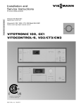
1
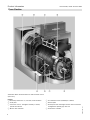
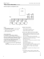
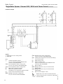
Technical Data Manual
for use by heating contractor
Vitorond 200, VD2A Series
Triple-pass hot water heating boiler
490 to 1096 MBH (144 to 321 kW)
VITOROND 200
Product may not be exactly as shown
Oil-/Gas-fired boiler
triple-pass sectional cast iron design with Eutectoplex heat transfer surface
and Therm-Control integrated low temperature protection logic
for operation with modulating water temperatures
Heating input:
490 to 1096 MBH
(144 to 321 kW)
5354 787 - 01 04/2014
Product Information
Vitorond 200, VD2A Technical Data
Safety and Installation Requirements
Please ensure that these instructions are read and
understood before starting any service work. Failure
to comply with these instructions may cause product/
property damage, severe personal injury and/or loss of life.
Ensure that main power to the equipment being serviced
is off.
Working on the equipment
Take precautions to avoid accidental activation of power
or fuel during service work.
The installation, adjustment, service and maintenance
of this product must be performed by a licensed
professional heating contractor who is qualified and
experienced in the installation, service, and maintenance
of hot water boilers. There are no user serviceable parts
on the boiler, burner or control.
Ensure that the main fuel supply valve to the boiler
is closed.
Do not perform service work on any component part
without ensuring safe operation of the heating system.
When replacing parts, use original Viessmann
or Viessmann approved replacement parts.
Refer to the Installation Instructions
applicable to this boiler.
Product Information
VITOROND 200
The benefits at a glance:
H Efficient and reliable operation.
Modulated boiler water temperatures help conserve
energy by closely matching system output to actual
demand. Viessmann system controls ensure consistent,
maximum system efficiency.
Combustion efficiency up to:
- oil . . . . . . . . . . . . . . . . . . . . . . . . . . . . . . . 87.7%.
- gas . . . . . . . . . . . . . . . . . . . . . . . . . . . . . . 84.8%.
Thermal efficiency up to:
- oil . . . . . . . . . . . . . . . . . . . . . . . . . . . . . . . 87.9%.
- gas . . . . . . . . . . . . . . . . . . . . . . . . . . . . . . 85.2%.
H Simplified design and system integration with ThermControl integrated low-temperature protection logic,
eliminating the need for a low-temperature protection
package or shunt pump.
No minimum boiler return water temperature when used
with Viessmann Vitotronic controls.
H Simplified water connection. Wide water galleries and a
large water content provide excellent natural circulation
and a reliable heat transfer. No minimum heating water
flow rate required.
H High operational reliability and a long service life are
achieved by the special Eutectoplex gray cast iron heat
exchanger. A uniform heat transfer and controlled water
flow, together with inherent characteristics of the cast
iron sections, eliminate stress fractures, counteract
the formation of condensate and extend the life cycle
of the boiler.
2
H Low environmental impact thanks to low-emission
combustion achieved by the boiler’s triple-pass design.
H Problem-free transport into difficult-to-access boiler
rooms thanks to sectional construction and low weight
of individual sections. The Fastfix system facilitates
a quick and easy installation.
H Simple, quick assembly of the individual cast iron
sections with new tongue-and-groove system with
silicone sealant. The gasket seal is secured in place
by the double groove, and therefore not subject to
mechanical stresses.
H Easy cleaning access facilitated by a hinged left- or
right-swing combustion chamber door providing easy
access to all three flue gas passageways from the front
of the boiler, reducing side clearance.
H Efficient and safe operation of the heating system with
Vitotronic digital boiler and heating system controls.
Tailored to suit every requirement, these controls
cover all known control strategies and applications.
Standardized LON BUS enables complete integration
into building management systems. Optional integration
into the Vitocontrol control panel.
H Consistent and reliable DHW production with indirectfired Vitocell 100 steel or Vitocell 300 stainless steel
tanks.
Tanks may be combined into multiple-tank batteries
for applications requiring larger quantities of hot water.
H Comprehensive standard equipment saves valuable
time in installation and sourcing of product. The supply
and return header system is pre-built for left or right
connections and positions components properly.
H Boilers, controls, domestic hot water tanks, and
heating system components are design-matched to
work together. All components are compatible and
are therefore quickly and easily installed.
5354 787 - 01
The Vitorond 200 is a triple-pass sectional cast iron oil-/
gas-fired boiler for commercial heating applications.
Its Eutectoplex heat exchanger provides high operational
reliability and a long service life, while the triple-pass
design ensures efficient, low-emission combustion.
The VD2A Series features Therm-Control integrated
low-temperature protection logic and a redesigned return
water distribution system for a simplified design and
system integration.
Vitorond 200, VD2A Technical Data
Table of Contents
Page
Product Information
Safety and Installation Requirements ............................2
Working on the equipment ......................................2
Product Information ....................................................2
VITOROND 200 .....................................................2
The benefits at a glance: ........................................2
Cross-Section ............................................................6
Technical Data
Technical Data ...........................................................7
Technical Data ......................................................7
Boiler Model ..........................................................7
Input (oil) ..............................................................7
Input (gas) ............................................................7
Output (oil/gas) .....................................................7
Combustion efficiency (oil) .....................................7
Combustion efficiency (gas) ...................................7
Thermal efficiency (oil) ...........................................7
Thermal efficiency (gas) .........................................7
Number of cast iron sections ...................................7
Cast iron block dimensions......................................7
Cast iron section dimensions ...................................7
Dimensions (with insul. jacket) ................................7
Technical Data ......................................................7
Boiler Model ..........................................................8
Weight Front section .............................................8
Overall weight
(complete with jacket, without burner) .....................8
Boiler water content ...............................................8
Max. boiler temperature ............................................. 8
Max. allow. operating pressure ................................8
Boiler connections..................................................8
Heating surface area ..............................................8
Flue gas - Temperature (gross) ................................8
Vent pipe collar outer .............................................8
Flue gas resistance ...............................................8
Required flue draft Category I ..................................8
Positive pressure Category III....................................8
Burner Installation ..................................................9
Boiler Connection Kit (standard equipment) .................10
Clearances to Combustibles .......................................11
Recommended Minimum Service Clearances ...........11
Waterside Flow ........................................................12
Recommended Flow Rates ....................................12
Boiler model VD2A ..............................................12
Burner Calibration .....................................................13
5354 787 - 01
Weishaupt burners / Riello burners .........................13
Model / Flue gas resistance ...................................13
Burner manufacturer ............................................13
Burner / Gas train approval....................................13
Electrical requirements .........................................13
Natural gas pressure ............................................13
New Casting Design and Therm-Control Functionality ...14
Redesigned Return Water Distribution System .........14
Therm-Control Low-Temperature Protection Logic ........15
3
Table of Contents
Vitorond 200, VD2A Technical Data
Page
Standard Equipment
Standard Equipment .................................................16
Standard equipment includes: ................................16
Boiler Control
Boiler Control Alternatives .........................................17
For single-boiler installations:.................................17
Vitotronic 100, GC1/GC1B ...................................17
Vitotronic 300, GW2/GW2B ..................................17
For multiple-boiler installations:..............................17
Vitotronic 100, GC1/GC1B ...................................17
Vitocontrol-S MW1/ Vitotronic 300-K, MW1B .........17
Vitotronic 100, GC1/GC1B ...................................17
Vitotronic 300-K MW1S/ Vitotronic 300-K, MW1B ..17
Vitocontrol equipment for multiple-boiler system ......18
Custom control panels ..........................................18
For single- or multiple-boiler installations: ................18
Single-Boiler System: Vitorond 200, VD2A
with Therm-Control ..................................................19
Applications ........................................................19
Main components ................................................19
Function description .............................................19
DHW heating..................................................... .19
Heating operation ................................................19
Wiring Diagram....................................................19
Installation Example .............................................20
Multi-Boiler System: Vitorond 200, VD2A
with Therm-Control ..................................................21
4
5354 787 - 01
Applications ........................................................21
Main components ................................................21
Function description .............................................21
DHW heating ......................................................21
Heating operation ................................................21
Installation Example..............................................22
Vitorond 200, VD2A Technical Data
Table of Contents
Page
System Design
System Design Considerations ...................................23
Burner calibration .................................................23
In Canada ...........................................................23
In U.S.A. ............................................................23
Venting (option #1) ..............................................23
Chimney .............................................................23
Barometric draft regulator type ..............................24
Barometric draft regulator diameter ........................24
Venting (option #2) ..............................................24
ProTech Systems Inc............................................24
Selkirk Canada Corporation ...................................24
Security Chimneys International Ldt. ......................24
Combustion air supply ..........................................25
System layout .....................................................25
Water quality and freeze protection ........................25
Oxygen diffusion barrier underfloor tubing ...............25
Factory pre-wired components ..............................25
Boiler/Burner start-up ...........................................25
Sound attenuation ...............................................26
Airborne noise attenuation ....................................26
Anti-vibration measures ........................................26
Seismic restrainer ................................................26
Warranty ............................................................26
Burner
Burner Alternatives ...................................................27
5354 787 - 01
Weishaupt Burners - Linkageless ............................27
Boiler Model.........................................................27
No. 2 oil-fired 2-stage ..........................................27
Natural gas-fired 2-stage.......................................27
Natural gas-fired fully modulating ...........................27
Propane gas-fired 2-stage .....................................27
Propane gas-fired fully modulating .........................27
Riello Burners ......................................................27
No. 2 oil-fired 1-stage ..........................................27
No. 2 oil-fired 2-stage ..........................................27
Natural gas-fired 1-stage.......................................27
Propane gas-fired 1-stage with assembled gas train..27
Natural gas-fired 2-stage with assembled gas train ...27
Propane gas-fired 2-stage with assembled gas train..27
Natural gas-fired fully modulating ...........................27
Propane gas-fired fully modulating .........................27
Combination 2-stage NG, 2-stage oil ......................27
Natural gas-fired fully modulating low NOx..............27
5
Product Information
Vitorond 200, VD2A Technical Data
Cross-Section
Viessmann North America offers the side-mounted control
option only.
6
E Low-emission burner (Weishaupt or Riello)
F Second pass
G Eutectoplex heat exchanger surface constructed from
homogeneous special gray cast iron
H Combustion chamber
5354 787 - 01
Legend
A Extremely effective 4 in. (100 mm) thick insulation
B Third pass
C Vitotronic control - intelligent and easy to install,
operate and service
D Burner door insulation
Technical Data
Vitorond 200, VD2A Technical Data
Technical Data
Boiler Model
VD2A-
125
160
195
230
270
Input (oil)*1
MBH (kW)
490 (144)
628 (184)
765 (224)
902 (264)
1059 (310)
Input (gas)*1
MBH (kW)
508 (149)
650 (190)
792 (232)
934 (274)
1096 (321)
Output (oil/gas)*2
MBH (kW)
433 (127)
553 (162)
672 (197)
794 (232)
932 (272)
Combustion efficiency (oil)
%
87.7
87.3
87.3
87.3
87.3
Combustion efficiency (gas)
%
84.7
84.8
84.8
84.8
84.8
Thermal efficiency
%
87.9
87.6
87.4
87.3
87.2
%
85.2
85.1
84.8
84.8
84.7
4
5
6
7
8
(oil)
Thermal efficiency (gas)
Number of cast iron sections
Cast iron block
dimensions*3
Length
(dimension f)
in.
(mm)
26b
(670)
33
(840)
39c
(1010)
46b
(1180)
53a
(1650)
Width
(dimension c)
in.
(mm)
31
(790)
31
(790)
31
(790)
31
(790)
31
(790)
Height
(dimension b)
in.
(mm)
35
(884)
35
(884)
35
(884)
35
(884)
35
(884)
62a
(1580)
40b
(1030)
34
(860)
39b
(1007)
58b
(1485)
Cast iron section dimensions*3
Front section
(with combustion chamber
door) (dimension j)
in.
(mm)
35 x 31 x 11b
(885 x 790 x 290)
Intermediate section
(dimension i)
in.
(mm)
34 x 26c x 6c
(860 x 680 x 170)
Rear section
(with flue gas collar)
in.
(mm)
35 x 34 x 10b
(885 x 860 x 270)
Dimensions (with insul. jacket)
Total length
(dimension g)
Total width with
side-mounted Vitotronic
control (dimension e)
Total width
(dimension d)
Total height with boiler base
(dimension h)
Total height with supply
header (dimension a)
*1
*2
5354 787 - 01
*3
*3
in.
(mm)
in.
(mm)
35c
(905)
40b
(1030)
42a
(1075)
40b
(1030)
49
(1240)
40b
(1030)
55b
(1410)
40b
(1030)
in.
(mm)
in.
(mm)
in.
(mm)
34
(860)
39b
(1007)
58b
(1485)
34
(860)
39b
(1007)
58b
(1485)
34
(860)
39b
(1007)
58b
(1485)
34
(860)
39b
(1007)
58b
(1485)
Input ratings are based on ANSI Z21.13a*CSA 4.9a-2007 - Gas Fired Steam and Hot Water Boilers; CSA B140.7-05
- Oil Burning Equipment - Steam and Hot Water Boilers; CSA B140.0-03 - Oil Burning Equipment - General
Requirements; UL 726 - 7th ed. - Oil-Fired Boiler Assemblies; and UL 795 - Commercial Industrial Gas Heating
Equipment.
Tested to AHRI BTS-2000 “method to determine efficiency of commercial space heating boilers”.
Inch dimensions are rounded to the nearest ¼ in.
7
Technical Data
Vitorond 200, VD2A Technical Data
Technical Data (continued)
Boiler Model
Weight Front section
(with combustion chamber door)
Intermediate section
Rear section
(with flue gas collar)
Cast iron heat exchanger block
Overall weight (complete with jacket,
without burner)
Boiler water content
Max. boiler temperature*4
(= fixed high limit)
Max. allow. operating pressure*5
Boiler connections*6
Boiler supply and return
Drain valve Boiler supply and return
Heating surface area
Flue gas side
Water side
VD2A-
125
160
195
230
270
lbs.
(kg)
352
(160)
352
(160)
352
(160)
352
(160)
352
(160)
lbs.
(kg)
lbs.
(kg)
lbs.
(kg)
lbs.
(kg)
USG (L)
ºF
(ºC)
220
(100)
242
(110)
1122
(510)
1201
(545)
32 (122)
250
(121)
220
(100)
242
(110)
1353
(615)
1441
(655)
41 (154)
250
(121)
220
(100)
242
(110)
1584
(720)
1675
(760)
49 (186)
250
(121)
220
(100)
242
(110)
1760
(800)
1874
(850)
57 (217)
250
(121)
220
(100)
242
(110)
1991
(905)
2127
(965)
66 (249)
250
(121)
psig
in.
85
2b
85
2b
85
2b
85
2b
85
2b
in.
ft2
(m2)
c
53
(4.9)
c
70
(6.5)
c
85
(7.9)
c
102
(9.5)
c
117
(10.9)
71
(6.6)
365 (185)
732
(332)
85
(7.9)
365 (185)
864
(390)
99
(9.2)
365 (185)
1014
(457)
257 (125)
439
(199)
0.28
257 (125)
516
(234)
0.25
257 (125)
604
(274)
0.25
8 (200)
0.40
7.169
(0,203)
0 (0)
20 (0.08)
8 (200)
0.48
8.299
(0.235)
0 (0)
20 (0.08)
8 (200)
0.64
9.429
(0.267)
0 (0)
20 (0.08)
ft2
43
57
(m2)
(4.0)
(5.3)
Flue gas - Temperature (gross)*7
ºF (ºC)
365 (185)
365 (185)
- Flue gas mass flow rate
lbs./h
470
602
(kg/h)
(213)
(273)
With minimum heating input and a 2-stage burner (operation of stage 1)
- Temperature
ºF (ºC)
257 (125)
257 (125)
- Flue gas mass flow rate at min.
lbs./h
282
362
input rate
(kg/h)
(128)
(164)
Standby loss based on max. heating
%
0.40
0.38
input and hot water supply and return
temps. of 167 / 140° F (75 / 60° C)
in. (mm)
8 (200)
8 (200)
Vent pipe collar outer 7*8
Flue gas resistance
“w.c.
0.26
0.38
Flue gas volume of combustion
ft.3
4.909
6.039
chamber and flue gas passageways
m3
(0.139)
(0.171)
Required flue draft Category I
Pa “w.c.
0 (0)
0 (0)
Positive pressure Category III
Pa “w.c. 20 (0.08)
20 (0.08)
*5
*6
*7
*8
8
The maximum supply operating temperature (= max. adjustable high limit) lies approx. 27° F (15° C) below the
fixed high limit setting.
May be less in some Canadian provinces.
Connections for boiler connection kit (standard equipment).
Combustion results are based on 13.0% CO2 with fuel oil #2 and 10% CO2 with natural gas, as well as a system
supply temperature of 167° F (75° C), and a system return temperature of 140° F (60° C). Measured flue gas
temperature with a combustion air temperature of 68° F (20° C) and a boiler water temperature of 176° F (80° C).
Vent pipe collar diameter does not automatically indicate vent/chimney size. See page 23 for different venting
options (categories).
The combustion burner head material must be suitable for temperatures of at least 932° F (500° C).
For information regarding other Viessmann System Technology componentry, please reference documentation of
respective product.
5354 787 - 01
*4
Technical Data
Vitorond 200, VD2A Technical Data
Technical Data (continued)
Burner Installation
64 in. (1623 mm)
*1
The burner must be fitted to the burner plate; installations
direct to the boiler door are not feasible.
Viessmann supplies a pre-drilled end burner plate
in accordance with the supplied burner dimensions.
Note: For mounting burners with blast tube diameters
over 6 in. (150 mm), the door insulation (refractory
material) can be cut to the required size.
The blast tube must protrude from the thermal
insulation on the boiler door.
CAUTION
*1
Dimension includes sub-base.
Note: Inch dimensions are rounded to the nearest 1/4 in.
Viessmann North America offers the side-mounted
control option only. Refer to the side-mounted control
dimension on page 4.
6c in.
(170 mm)
BWS
LWCO
10 7/8 in.
38 in. (970 mm)
31a in. (795 mm)
18a in. (465 mm)
FGC
Legend
BD
Boiler drain ¾ in.
BWR Boiler water return
BWS Boiler water supply
CO
Clean-out opening
FGC Flue gas collar
SG
Sight glass
LWCO Low water cut-off
7 6 in. (150 mm)
25a in. (640 mm)
18a in. (465 mm)
18a in. (465 mm)
BWR
(275 mm)
5354 787 - 01
5 in. (125 mm)
9
Technical Data
Vitorond 200, VD2A Technical Data
Boiler Connection Kit (standard equipment)
BWS
LWCO
SS
7¾ in. (195 mm)
TG
57/8 in. (148 mm)
19e in. (490 mm)
Dual
Aquastat
(optional)
*1
9f in. (245 mm)
Legend
SS
LWCO
TG
BWS
Safety supply - connection to pressure relief valve
Low water cut-off
Temperature gauge
Boiler water supply
Note: Inch dimensions are rounded to the nearest 1/4 in.
10
9f in. (245 mm)
IMPORTANT
*1
Boiler must be controlled via Viessmann Vitotronic
Therm-Control logic in order to prevent the formation
of flue gas condensation at all local site return water
temperatures. Consult your local Viessmann Technical
Representative for other possible control options.
5354 787 - 01
Single
Aquastat
(optional)
*1
Technical Data
Vitorond 200, VD2A Technical Data
Clearances to Combustibles
Boiler model
VD2A-
125
160
195
230
Top
6 in. (150 mm)
Sides
6 in. (150 mm)
Flue (oil)
9 in. (229 mm)
Flue (gas)
6 in. (150 mm)
Front
6 in. (150 mm)
Floor
non-combustible
Boiler model
VD2Aa1
125
160
195
270
H Protect against frost and ensure good ventilation
Otherwise, the system may suffer faults and damage.
In rooms where air contamination through halogenated
hydrocarbons may occur, install the boiler only if
adequate measures can be taken to provide a supply
230
270
Dependent on burner model
Inch dimensions rounded to the nearest ¼ in.
1
2
Minimum clearance in front of boiler
Burner length [plus 8 in. (200 mm) for door clearance
to wall].
Recommended Service Clearances
20 in.
(500 mm)
A
a
Maintain 1 in. air clearance from uninsulated hot water
pipes to combustible material.
IMPORTANT
Boiler must not be installed on combustible floor material
The combustion chamber door is factory assembled
to hinge on the left-hand side. A right-hand hinge
is feasible by rebuilding the door hinge hardware.
IMPORTANT
Minimum side clearance of 20 in. (500 mm) must
be maintained for side-mounted Vitotronic controls.
6c in.
(170 mm)
20 in.
(500 mm)
Top Views
5354 787 - 01
IMPORTANT
Front clearances (dimension “a”) will allow for easy
removal of flue gas turbulator inserts, as well as for full
insertion of bristle brush for heat exchanger cleaning.
17 in.
(430 mm)
24 in.
(600 mm)
H Avoid very dusty conditions
H Avoid high levels of humidity
in. 47¼
55
63
71
79
(mm) (1200) (1400) (1600) (1800) (2000)
b2
H Avoid air contamination by halogenated hydrocarbons
(e.g. as in sprays, paints, solvents and cleaning agents)
b
8 in.
(200 mm)
11
Technical Data
Vitorond 200, VD2A Technical Data
Waterside Flow
The Vitorond 200 boiler is designed for closed loop,
forced circulation, hot water heating systems only.
The recommended water flow rate through the Vitorond
200 is based on a temperature difference of between
20° F and 40° F (11° C and 22° C) (see table below).
Pressure Drop
When a balancing valve is used for proper balancing
and water flow through the boiler, the valve should be
installed 5 pipe diameters from any fittings and 10 pipe
diameters from circulation pumps to allow for laminar
flow.
The consulting engineer or contractor should review
the system design if more balancing valves are required
to properly balance the system.
Viessmann can supply TA (Victaulic) balancing valves
upon request. The balancing should be carried out by
a certified balancing firm prior to boiler start-up. Please
contact Viessmann for your closest certified balancing
firm.
Flow Rate
Legend
A VD2A-125, VD2A-160
B VD2A-195
C VD2A-230 and VD2A-270
Recommended Flow Rates
Boiler model
VD2A-
125
160
195
230
270
20° F ∆t
GPM
43
55
67
79
92
40° F ∆t
GPM
21
27
33
39
46
11° C ∆t
L/s
2.7
3.4
4.2
5.0
5.8
22° C ∆t
L/s
1.3
1.7
2.1
2.5
2.9
12
5354 787 - 01
∆t = temperature difference
Technical Data
Vitorond 200, VD2A Technical Data
Burner Calibration
Weishaupt burners / Riello burners
A Vitorond 200, VD2A boiler with a high-performance gas
burner installed can achieve a thermal efficiency of up to
85.2%, and up to 87.9% if equipped with a #2 oil burner
as follows:
Gas-fired
10% volume CO2, 280° F (138° C) net stack
temperature, CO in ppm < 50
Oil-fired
13% volume CO2, 300° F (149° C) net stack
temperature, smoke spot 0 - 1 (on the Bacharach Scale)
See separate instructions supplied with the burner.
The maximum input published for each boiler size must
not be exceeded.
Model
Flue gas resistance
mbar
“w.c.
VD2A-125
0.65
0.26
VD2A-160
0.95
0.38
VD2A-195
1.0
0.40
VD2A-230
1.2
0.48
VD2A-270
1.6
0.64
Burner manufacturer
Weishaupt or Riello
Burner/Gas train approval
Standard approvals are CSA (for Canada) and UL (for U.S.).
IRI and FM approved equipment is also available - please
inquire.
Electrical requirements
Weishaupt W Series and Riello burners are available
in 120 VAC, single-phase, in a 60 Hz configuration.
It is generally acceptable to use voltages within ten
percent of the supply voltage. Available voltage inside
boiler room must be provided at time of order. Ensure
appropriate disconnect means and overcurrent protection.
Natural gas pressure
Natural gas pressures and heating values as provided by
the gas utilities vary greatly across North America. Select
the appropriate gas train accordingly. Low pressure gas
trains have a maximum input of 14 ”w.c.; high pressure
gas trains have a maximum pressure of 5 psig.
5354 787 - 01
Minimum gas pressures apply - please inquire. Gas
pressures and heating values at site must be provided at
time of order.
13
Technical Data
Vitorond 200, VD2A Technical Data
New Casting Design and Therm-Control Functionality
A specific, matching boiler control is part of the standard
equipment of the Vitorond 200, VD2A.
Boiler protection is assured by the following:
- Therm-Control logic
- Control of a shunt pump
- Flow rate reduction in the heating circuits
- Constant return temperature control
The cast iron mid-sections were re-designed to increase
the heat exchanger surface area and water volume, and
the number of cast iron sections was reduced by one
section.
Together with the redesigned return water distribution
system and the Therm-Control low-temperature protection
logic, this eliminates the need for a minimum return water
temperature.
VD2 cast iron section
The larger water volume and increased width of the flue
passages also ensure even heating of the water and
reduced burner cycling.
A new tongue-and-groove system with silicone sealant
replaces the fiber-rope seal between sections used with
the VD2 Series.
System return water enters the cast iron sections of the
VD2A boiler via a return water distribution tube now
located at the top of the cast iron block (see illustration).
Heated supply water flows at the bottom of the cast iron
block towards the rear section and upward to the supply
connection. The return water temperature is elevated
when passing through the rear cast iron section where
the supply water flows upward to the boiler supply
connection.
VD2A cast iron section
Redesigned Return Water Distribution System
Boiler supply
Return water
Therm-Control
distribution tube sensor
Boiler
return
The pre-heated return water is then distributed to the
cast iron sections through two upward-pointing openings
in the distribution tube at each section. The size of the
opening is proportional to the amount of heat input of
each cast iron section. In each section the return water
flows downward and mixes with heated water. Once fully
heated, the supply water flows through the bottom of
the cast iron block up the rear section and out the boiler
supply to the system.
14
5354 787 - 01
The even temperature distribution ensured by this design
reduces the thermal stress on the heat exchanger and,
in conjunction with the Vitotronic Therm-Control logic,
prevents the formation of flue gas condensate at all return
water temperatures, eliminating the need for a shunt
pump or return temperature elevation provided by a Low
Temperature Protection (LTP) Package.
Technical Data
Vitorond 200, VD2A Technical Data
Therm-Control Low-Temperature Protection Logic
A specific, matching boiler control is part of the standard
equipment of the Vitorond 200, VD2A. Boiler protection
is assured by the following:
Example:
Take a heating system with one heating circuit and
a mixing valve.
H Therm-Control logic
In the start-up phase, the set Therm-Control temperature
is not achieved at the Therm-Control sensor.
H Control of a shunt pump
H Flow rate reduction in the heating circuits
H Constant return temperature control
Therm-Control is an integrated low-temperature
protection logic provided by the Vitotronic control.
The control uses a Therm-Control temperature sensor
specifically positioned in the casting close to the boiler
return (shown in Fig. 8 on page 11) to capture the
thermal state of the boiler (i.e. the temperature of the
system return mixed with the boiler water) and react
as early as possible. The Therm-Control Logic shuts off
the system pump (and, if applicable, closes the mixing
valve) and brings the burner to full fire until the boiler
minimum setpoint temperature is reached during start-up,
preventing the formation of flue gas condensation and
allowing for maximum heat transfer to the system.
5354 787 - 01
This ensures steady supply temperatures with only
minimal fluctuations, and eliminates the need for a shunt
pump or return temperature elevation provided by a
Low Temperature Protection (LTP) Package.
The mixing valve downstream of the boiler receives
a signal via the control to reduce the flow rate and to
operate the burner at full fire (Phase 1 as shown).
The boiler temperature and that captured by the ThermControl sensor now rapidly rise. The mixing valve opens
when the set temperature is exceeded at the ThermControl sensor, and the flow rate (in this example 50 %)
inside the boiler is steadily increased (Phase 2).
The return water temperature rises after a certain time has
elapsed which is a function of the system water volume.
As the return temperature rises, the mixing valve opens
further until the maximum flow rate (100%) is achieved.
Now the control will modulate the burner firing rate to
achieve the required setpoint (burner modulation), and
weather-responsive boiler water temperature modulation
will take place.
15
Standard Equipment
Vitorond 200, VD2A Technical Data
Standard Equipment
Note: Boiler controls and burners are purchased
separately. Please see Price List for details.
H The cast iron sections are delivered as individual units
on skids.
H The combustion chamber door is mounted on the front
section.
H The flue gas collector, with two inspection opening
covers (fastened with screws), is mounted on the rear
section.
1
1
1
1
carton
carton
carton
carton
containing
containing
containing
containing
supply and return headers
insulation panels and cleaning brushes
the boiler control
installation fittings with safety header
Standard equipment includes:
- Boiler base with leveling bolts
- Connection piping with counter flanges and gaskets
- Turbulators are packed in a bag and placed inside the
combustion chamber
When cast iron sections are delivered as individual units:
- Push nipples, high temperature silicone and linseed oil
with graphite based sealant are packed in a carton and
placed inside the combustion chamber
IMPORTANT
16
5354 787 - 01
Ensure specific regional, provincial, or state requirements,
such as fuel train and additional safety control
requirements etc., are known before the product order is
placed, to determine proper burner selection and pricing.
Boiler Control
Vitorond 200, VD2A Technical Data
Boiler Control Alternatives
For single-boiler installations:
Vitotronic 100, GC1/GC1B
*1
For multiple-boiler installations:
Vitotronic 100, GC1/GC1B
*1
- Electronic boiler control unit for a constant boiler water
temperature or weather-compensated operation in
conjunction with a Vitocontrol panel with Vitotronic
300-K (type MW1S) or an external control unit
Digital boiler control systems for modulating boiler and
common supply temperature control.
- For two-stage or modulating burners
- Optional communication via LON
- With control unit for DHW primary system with mixing
valve assembly or as an alternative to the control of a
constant return temperature with a regulated three-way
valve
- With internal diagnostic system
- A function extension to default the set boiler water
temperature via 0 - 10 V input can be connected
(optional)
External demand:
- Enable boiler/open butterfly valve
- Burner stage 1 ON
- For two-stage or modulating burners
Vitocontrol-S MW1/Vitotronic 300-K, MW1B
*1
- Weather-compensated cascade control unit for multiboiler systems with up to 4 boilers with the Vitotronic
100 (GC1/GC1B)
- For up to 2 heating circuits with mixing valve with time
switch offering individual and 7-day programs
- Programming unit with plain text prompts
- With control unit for DHW primary systems with mixing
valve assembly
- With lead boiler selection
- Optional communication via LON
- Burner stage 1 and 2 ON
- With integral diagnostic system and additional functions
- Isolation valve “close”
Provide a potential free contact for each demand.
Connect the potential free contacts to plug-in connectors
aVD and/or aVH.
Vitotronic 300, GW2/GW2B
- Electronic boiler control unit
*1
- Weather-compensated, digital boiler and heating circuit
control unit
- For single-boiler systems
- A function extension to default a set system flow
temperature via a 0 - 10 V input can be connected
(optional)
An extension kit is required for each heating circuit with
mixing valve
*1
See respective product manuals for details. Please
inquire with your Viessmann Representative for further
assistance.
- For up to 2 heating circuits with mixing valve
- For two-stage or modulating burners
- With time switch offering individual and 7-day programs
- Programming unit with plain text prompts
- With separately adjustable periods and heating curves
- With control for DHW primary systems with mixing
valve assembly or alternatively, for the control of a
constant return temperature with a regulated three-way
valve
- With internal diagnostic system
- A function extension to default the set boiler water
temperature via 0 - 10 V input can be connected
(optional)
5354 787 - 01
An extension kit is required for each heating circuit with
mixing valve. The LON communication module is required
to enable communication.
17
Boiler Control
Vitorond 200, VD2A Technical Data
Boiler Control Alternatives (continued)
Vitocontrol equipment for multiple-boiler system
Legend
A Up to 4 boilers with a Vitotronic 100, GC1/GC1B
B Outside temperature sensor
C Vitocontrol control panel with Vitotronic 300-K,
MW1S/Vitotronic 300-K, MW1B
D Flow temperature sensor
Custom control panels
For single-boiler or multiple-boiler installations:
Vitotronic 100, GC1/GC1B
*1
- Electronic boiler control unit
- For two-stage or modulating burners
- Optional communication via LON
Vitotronic 300-K, MW1S/Vitotronic 300-K, MW1B
*1
- Weather-compensated cascade control unit for multiboiler systems with up to 4 boilers with the Vitotronic
100, GC1/GC1B
Custom control panels for residential or commercial
applications are designed and manufactured by Viessmann
to suit any customer’s specific requirements. Custom
control panels can have features such as pool heating,
hot tub heating, snow melting, telephone tie-in,
integration with Building Management Systems, as well
as several other functions. Please inquire.
- For up to 2 heating circuits with mixing valves
Note: The control of the Vitorond 200, VD2A boiler can
be mounted either on the left- or right-hand side of
the boiler.
Please specify control location at the time of order.
- With lead boiler selection
- With time switch offering individual and 7-day programs
- Programming unit with plain text prompts
- With DHW thermostat
- With control unit for DHW primary systems with mixing
valve assembly
- Optional communication via LON
- With integral diagnostic system and additional functions
- A function extension to default a set system flow
temperature via a 0-10 V input can be connected
(accessories)
*1
18
See respective product manuals for details. Please
inquire with your Viessmann Representative for further
assistance.
5354 787 - 01
An extension kit is required for each heating circuit with
mixing valve.
Boiler Control
Vitorond 200, VD2A Technical Data
Single-Boiler System: Vitorond 200, VD2A with Therm-Control
Applications
Heating system with manifold installed close to the boiler.
The boiler water flow rate must be able to be reduced.
Main components
Single boiler system with:
H Vitorond 200, VD2A, 125 to 270.
H Vitotronic 300, GW2/GW2B model or Vitotronic 100,
GC1/GC1B model with Vitocontrol panel and integral
weather-compensated Vitotronic 200-H, HK1M/HK1B
model or Vitotronic 100, GC1/GC1B model and external
weather-compensated control unit.
Wiring Diagram
The Therm-Control wiring in heating systems with heating
circuit control units, is not connected to the boiler control
unit via the LON.
Required coding:
Change “4C” to “2” - use the plug-in connector sÖA1
to close the downstream mixing valve. Change “0D”
to “1” - the Therm-Control acts on the mixing valve of the
downstream heating circuits (for Vitotronic 200 and 300,
factory set condition).
H Therm-Control for operating boilers without low
temperature return package.
Function description
The Therm-Control will affect the heating control
unit(s) or the heating circuit pump(s), if the factoryset temperatures are not reached at the Therm-Control
temperature sensor. In the start-up phase (e.g. during
commissioning or after a night or weekend shutdown),
the boiler water flow rate must be reduced by at least 50%.
The boiler is protected to an optimum level when using
the Vitotronic 300, GW2/GW2B model or if the heating
circuits are regulated via a Vitotronic 200-H connected
to the boiler control unit. No additional on-site protective
measures are required.
When it is impossible to reduce the boiler water flow
rate, e.g. in older systems, we recommend contacting
Viessmann for other possible piping layouts.
No minimum return water temperature needs to be
maintained. Shunt pumps and/or boiler circuit pumps/
costly mixing valves are not required for elevating the
return temperature.
DHW heating
The DHW is heated up when the actual temperature
falls below the DHW temperature selected for the tank
temperature sensor, subject to tank heating being enabled
by the time switch.
Closed
1
Closed
Closed
2 ...n
Legend
A
Contactor relay, field supplied
sÖA1 Closing mixing valves (Vitotronic 100, GC1/GC1B)
A
Contactor relay, field supplied
B
Downstream heating circuit control unit
Switching contact closed:
signal for close mixing valve(s)
C
Power connection 120 VAC 60 Hz
D
Junction box, field supplied
The boiler water temperature is raised to the set DHW
temperature +20 K (36º F) and the tank primary pump
is started, if the boiler water temperature is 7 K (12.6º F)
above the actual DHW temperature.
5354 787 - 01
The heating circuit pumps M2 and M3 are closed, subject
to absolute priority being enabled, if the heating circuits
are regulated via the Vitotronic. Subject to modulating
priority, the heating circuit pumps M2 and M3 remain
switched ON and the mixing valves M2 and M3 are closed
far enough for the set boiler water temperature for tank
heating to be achieved.
Heating operation
Depending on the control unit used, the flow temperature
of heating circuits can be operated in modulating mode,
subject to the outside temperature. The boiler water
temperature is regulated 8 K (14.4º F) higher than the set
flow temperature.
19
Boiler Control
Vitorond 200, VD2A Technical Data
Single-Boiler System: Vitorond 200, VD2A with Therm-Control (continued)
Installation Example
Plug
Outdoor temperature sensor
(only for Vitotronic 200 HK1M/HK1B and
Vitotronic 300 GW2/GW2B)
?M2 Flow temperature sensor, mixing valve
(only for the Vitotronic 300 GW2/GW2B)
?M3 Flow temperature sensor, mixing valve
§
Boiler water temperature sensor
%
DHW tank temperature sensor
(accessory for the Vitotronic 100 GC1/GC1B)
aJA Therm-Control temperature sensor
sÖM2 Heating circuit pump, mixing valve
(only for Vitotronic 300 GW2/GW2B)
!
20
sÖM3 Heating circuit pump, mixing valve
(only for Vitotronic 300 GW2/GW2B)
sÖA1 Closing the mixing valves with external heating
circuit control units
sA
DHW primary pump
sK
DHW circulation pump
(only for the Vitotronic 200 HK1M/HK1B and
Vitotronic 300 GW2/GW2B)
fA
Burner (stage 1)
gSM2 Mixing valve motor (only for Vitotronic 300
GW2/GW2B)
gSM3 Mixing valve motor (only for Vitotronic 300
GW2/GW2B)
lÖ
Burner (burner stage 2 / mod.)
Please refer to the control manuals Vitotronic
100 GC1/Vitocontrol-S or Vitotronic 100 GC1B/
Vitotronic 300-K
5354 787 - 01
Legend
A Heating circuit with mixing valves
B DHW tank
Boiler Control
Vitorond 200, VD2A Technical Data
Multi-Boiler System: Vitorond 200, VD2A with Therm-Control
Applications
Heating system with manifold installed close to the
boiler. The boiler water flow rate will be reduced via the
motorized butterfly valve.
Main components
Multi-boiler system with:
H Vitorond 200, VD2A, 125 to 270.
H Vitotronic 200-H and
- Vitotronic 100, GC1/GC1B, for every boiler in a
multi-boiler system
and
Vitocontrol-S MW1/Vitotronic 300-K, MW1B, one
required for multi-boiler systems
or
- Vitotronic 100, GC1/GC1B, for every boiler in a
multi-boiler system and
Vitocontrol control panel and integral weathercompensated control unit Vitocontrol-S MW1/
Vitotronic 300-K, MW1B
- external, weather-compensated cascade control unit
with tank thermostat
H Therm-Control for operating boilers without return
temperature elevating package.
Function description
The Therm-Control will regulate the motorized butterfly
valves or the heating circuit control unit(s), if the factoryset temperatures are not reached at the Therm-Control
temperature sensor. In the starting phase (e.g. during
commissioning or after a night or weekend shutdown),
the boiler water flow must be proportionally reduced.
Reduce the flow rate via the heating mixing valve using
the Vitotronic-S MW1/Vitotronic 300-K, MW1B or when
regulating the heating circuits via a Vitotronic 200H connected to the boiler control unit. No additional
protection measures are required on-site.
No minimum return temperature needs to be maintained.
No shunt pumps and/or boiler circuit pumps/costly mixing
valves are required for raising the return temperature.
DHW heating
DHW is heated up when the actual temperature falls
below the DHW temperature selected for the tank
temperature sensor, subject to tank heating being enabled
by the time switch. The boiler water temperature is raised
to the set DHW temperature +20 K (36º F) and the tank
primary pump is started, if the boiler water temperature
is 7 K (12.6º F) above the actual tank temperature.
The heating circuit pumps M2 and M3 are switched OFF
and the mixing valves M2 and M3 are closed, subject
to absolute priority being enabled, if the heating circuits
are regulated via the Vitotronic.
Heating operation
5354 787 - 01
Depending on the control unit used, the flow temperature
of heating circuits can be operated in modulating mode,
subject to the outside temperature. The boiler water
temperature is regulated 8K (14.4º F) higher than the
set-point.
21
Boiler Control
Vitorond 200, VD2A Technical Data
Multi-Boiler System, Vitorond 200, VD2A with Therm-Control (continued)
Installation Example
Plug
Outdoor temperature sensor
(only for Vitocontrol-S MW1/Vitotronic 300-K, MW1B)
?Flow Flow temperature sensor, common heating flow
(only for Vitocontrol-S MW1/Vitotronic 300-K, MW1B)
?M2 Flow temperature sensor, mixing valve
(only for Vitocontrol-S MW1/Vitotronic 300-K, MW1B)
?M3 Flow temperature sensor, mixing valve
(only for Vitocontrol-S MW1/Vitotronic 300-K, MW1B)
?
Flow temperature sensor Vitotronic 200-H
§
Boiler water temperature sensor
%
DHW tank temp. sensor (only for Vitocontrol-S MW1
/Vitotronic 300-K, MW1B)
aJA
Therm-Control temperature sensor
sÖM2 Heating circuit pump, mixing valve
(only for Vitocontrol-S MW1/Vitotronic 300-K, MW1B)
!
22
Heating circuit pump, mixing valve
(only for Vitocontrol-S MW1/Vitotronic 300-K, MW1B)
sÖ
Heating circuit pump Vitotronic 200-H
sK
DHW circulation pump
(only for Vitocontrol-S MW1/Vitotronic 300-K, MW1B)
fÖ
Power supply, 120 VAC 60 Hz
Install the main isolator in accordance with
regulations
fA
Burner (stage 1)
gSA1
Motorized butterfly valve
gSM2 Mixing valve motor (only for Vitocontrol-S MW1
/Vitotronic 300-K, MW1B)
gSM3 Mixing valve motor (only for Vitocontrol-S MW1
/Vitotronic 300-K, MW1B)
gSM3 Mixing valve motor, Vitotronic 200-H
lÖ
Burner
(burner stage 2 / mod.)
aVD/aVH External connections
sÖM3
Please refer to the control manuals Vitotronic
100, GC1/GC1B and Vitotronic Vitocontrol-S
MW1/300-K MW1B.
5354 787 - 01
Legend
LON
LON connection (available connections with
terminator)
A
Heating circuit with mixing valves
B
DHW tank
System Design
Vitorond 200, VD2A Technical Data
System Design Considerations
Burner calibration
Venting (option #1)
With 2-stage and fully modulating burners, ensure
that the chimney is compatible with the lower flue gas
temperatures associated with partial load conditions set
on the burner.
The Vitorond 200, VD2A boiler is approved as a Category I
appliance and must be vented accordingly.
WARNING
When installing or insulating (overhead) piping
or venting, do not stand on top panel of boiler.
Advise other trades accordingly!
CAUTION
The Vitorond 200, VD2A boiler is not approved for side
wall venting.
Chimney
For proper operation of the Vitorond 200, VD2A boiler,
all products of combustion must be safely vented to
the outdoors, while ensuring that flue gases do not cool
prematurely.
It is critical that the chimney system be properly designed
to handle the relatively cool flue gas temperatures
produced by the Vitorond 200, VD2A boiler.
If the chimney system lacks sufficient insulation and/or
the chimney diameter is too large, corrosive and damaging
condensation will result due to flue gases cooling too
quickly. If a calculated chimney diameter lies between two
values, the larger diameter should be selected.
Never operate boiler without an installed venting system
which safely vents all products of combustion to the
outdoors.
The chimney connection length between the boiler vent
pipe collar and the chimney must be installed with
insulation.
The vent system must comply with all applicable local
and/or national codes.
Vent pipe collar diameter does not automatically
indicate vent/chimney size.
Vitorond 200, VD2A boilers are Category I and III boilers
as defined in ANSI Z21.13 when used with natural gas
and LP. Venting systems shall be sized and constructed in
accordance with approved engineering methods (ASHRAE,
HVAC Systems and Equipment Handbook, Chapter 31
“Chimney, Gas Vent, and Fireplace Systems”) including
the chimney and boiler manufacturer’s instructions.
We recommend consulting a reputable chimney installer
for advice in project-specific circumstances.
In Canada
When installing the Vitorond 200, VD2A boiler,
it is necessary to install a barometric draft regulator
in the chimney/vent for proper operation of the boiler.
Install the barometric draft regulator within 5 to 7 ft.
(1½ to 2 m) from the breeching outlet located at the
rear of the boiler.
For gas-fired boilers install venting system in accordance
with all applicable local codes.
In the absence of local codes, follow national codes CAN/
CSA B149.1 or .2 or latest edition.
For oil-fired boilers follow CSA B-139 or latest edition.
In U.S.A.
5354 787 - 01
For gas-fired boilers connecting to gas vents or chimneys,
vent installations shall be in accordance with Venting of
Equipment of the National Fuel Gas Code, ANSI Z223.1
or applicable provisions of the local building codes.
For oil-fired boilers follow NFPA 31. Always use latest
code editions.
23
System Design
Vitorond 200, VD2A Technical Data
System Design Considerations (continued)
Barometric draft regulator type
Venting (option #2)
For natural gas or propane applications, use a doubleacting type.
The Vitorond 200 boiler is a Category III positive pressure
non-condensing boiler.
For #2 fuel oil applications, use a single-acting type.
Each boiler must be vented individually.
Barometric draft regulator diameter
The barometric draft regulator must be the same diameter
opening as the chimney for which the vent is sized.
For example, a 14 in. chimney would require a 14 in.
barometric draft regulator. Do not size the barometric
draft regulator to the breeching outlet of the boiler, unless
the chimney is also intended to be of that diameter.
The vent system must be properly designed and suitable
materials must be selected. The chimney must be gas
tight.
Use an AL29-4C® special stainless steel venting system
(UL/ULC listed for Category III) for single-wall vertical
venting of the Vitorond 200 boiler.
For more details on the positive pressure venting option,
see the Viessmann installation instructions for the positive
pressure venting system.
IMPORTANT
The flue size outlet on the boiler does not automatically
determine the horizontal breeching, or the actual chimney
diameter.
The chimney size must be designed for the actual boiler
model and its respective input.
The following manufacturers may be contacted for
suitable stainless steel chimneys:
ProTech Systems Inc.
26 Gansevoort Street
Albany, NY 12202
Tel.: (518) 463-7284
Fax: (518) 463-5271
Toll free: 1-800-766-3473
Selkirk Canada Corporation
375 Green Road
Stoney Creek, ON L8E 4A5
Tel.: (905) 662-6600
Fax: (905) 662-5352
(US) 1-800-992-8368
(Canada) 1-888-735-5475
Email: [email protected]
Web: www.selkirkchimney.com
24
Security Chimneys International Ltd.
2125 Rue Monterey, Laval, Quebec H7L 3T6
Tel. 450-973-9999
(US) 1-800-361-4909
(Canada) 1-800-667-3387
Fax: 450-973-2222
Email: [email protected]
Web: www.securitychimneys.com
5354 787 - 01
Barometric draft regulator
System Design
Vitorond 200, VD2A Technical Data
System Design Considerations (continued)
Combustion air supply
Water quality and freeze protection
The boiler must not be located in areas or rooms where
chemicals containing chlorine, bromine, fluorine, or other
corrosive chemicals are stored. Examples include
refrigerants, bleach, paint, paint thinner, hair spray,
cleaning solvents, water softener salt, etc. The
combustion air must not be contaminated with any
amount of the above mentioned chemicals.
Treatment for boiler feed water should be considered
in areas of known problems, such as where a high mineral
content and hardness exist. In areas where freezing might
occur, an antifreeze may be added to the system water
to protect the system.
Boiler should never be installed in areas where excessive
dust, high humidity, or risk of frost exist. Ensure adequate
ventilation and supply of fresh combustion air.
Consult Viessmann with uncertainties in regard to
a suitable boiler installation location.
This boiler/burner unit needs clean fresh air for safe
operation. Provisions for combustion and ventilation air
must be made in accordance with applicable local codes.
In the absence of local codes, use CAN/CSA-B149.1 or .2
Installation Codes for Gas Burning Appliances for Canada.
For U.S. installations use section 5.3, Air for Combustion
and Ventilation, of the National Fuel Gas Code ANSI
Z223.1.
For oil burning installations use CSA B-139 for oil
installations in Canada and NFPA 31 Standard for the
Installation of Oil Burning Equipment in the US. Always
use latest editions of codes.
Whenever possible, install boiler near an outside wall so
that it is easy to duct fresh air directly to the boiler area.
Refer to national codes for duct sizing and allowable
lengths. Round ducts can be used.
The boiler location must never be under negative pressure.
Exhaust fans, attic fans, or dryer fans may cause air to be
exhausted at a rate higher than air can enter the structure
for safe combustion.
System layout
The boiler water temperature limit is factory set to 167° F
(75° C).
The boiler water temperature limit can be increased by
altering the adjustable high limit to increase the supply
water temperature.
To minimize piping losses of the system, however,
Viessmann recommends that the radiation and domestic
hot water production in the system be designed for
a 158° F (70° C) boiler supply water temperature.
Please adhere to the specifications given by the antifreeze
manufacturer. Do not use automotive silicate-based
antifreeze. Please observe that an antifreeze/water
mixture may require a backflow preventer within the
automatic water feed and influence components such
as diaphragm expansion tanks, radiation, etc.
A 40% antifreeze content will provide freeze-up
protection to -10° F (-23° C). Do not use antifreeze
other than specifically made for hot water heating
systems. System also may contain components which
might be negatively affected by antifreeze. Check total
system frequently when filled with antifreeze.
Follow the instructions of antifreeze manufacturer.
Oxygen diffusion barrier underfloor tubing
The boiler warranty does not cover leaks resulting from
corrosion caused by the use of underfloor plastic tubing
without an oxygen diffusion barrier. Such systems
must have the tubing without oxygen diffusion barrier
separated from the boiler with a heat exchanger.
Viessmann recommends the use of underfloor plastic
tubing with an oxygen diffusion barrier.
Factory pre-wired components
Custom factory pre-wiring by Viessmann ensures optimal
functionality, compliance with regional requirements,
and ease of installation in the field. Pricing provided
by Viessmann includes all necessary hardware items such
as junction panel, burner power supply, boiler door safety
switch (where necessary), and all essential pressure
switches, as well as interconnection with conduit
between control and burner.
Electrical drawings provided upon product delivery.
Boiler/Burner start-up
Vitorond 200, VD2A boilers with Weishaupt burners
require start-up by Viessmann.
Please inquire to obtain details regarding the necessary
prerequisites of boiler/burner start-up procedures.
5354 787 - 01
IMPORTANT
To minimize delivery lead times, please ensure that
critical technical information is provided at time of order.
Viessmann will not process an order without site-specific
information regarding available voltage and gas pressure.
In addition Viessmann recommends that gas pressure
information be provided in writing by the local gas utility.
25
System Design
Vitorond 200, VD2A Technical Data
System Design Considerations (continued)
Sound attenuation
Anti-vibration measures
Please consult a professional engineer who is specialized
in noise attenuation for advice.
Anti-vibration supports can be field supplied as an
economical and effective solution to combat noise
generated.
The burner/boiler systems, circulation pumps and other
auxiliary equipment used in heating systems generate
noise. This noise is transferred from the boiler room via
floorboards, ceiling and walls to neighboring rooms and
via the flue gas system as well as the ventilation air and
exhaust air apertures into other rooms and into the open,
where they may cause a nuisance.
To avoid this from happening, additional protective
measures may be required which should be considered
at the design stage. Subsequent measures to reduce
noise nuisance frequently require extensive effort and
expenditure.
Airborne noise attenuation
Frequently, modern boilers are equipped with silencer
hoods or sound insulated ventilation air inlet housings.
Additional silencer hoods may be used where more
stringent anti-noise measures are required. These
measures may be implemented later with minimal effort.
Silencer hoods are offered (usually by the burner
manufacturer) for various levels of noise attenuation
and are generally designed and built in accordance with
specific system conditions (boiler type, fuel supply,
building characteristics).
For larger systems, it may be necessary to route the
ventilation air through a sound-insulated channel, in order
to avoid noise nuisance outside the building.
Flue gas silencers are generally only required where higher
noise protection measures are called for. Whether or not
a flue gas silencer is required can be difficult to predict,
because of the complexity of the creation and propagation
of flame noise, the interaction between the burner, boiler
and the flue gas system as well as the operating mode
(flue gas system operating with positive or negative
pressure).
When sizing such supports, take the entire operating
weight of the boiler system and, when using longitudinal
anti-vibration brackets, the condition of the supporting
surface into consideration.
Effective anti-vibration measures are particularly important
when installing boilers into an attic. Compensators may
be used to physically separate the combustion equipment
from the building.
These should be installed into the boiler flow, return
and safety pipe and as near as possible to the boiler.
Also insulate any braces or hanging arrangements,
if installed, against sound/ vibration transmission to the
building.
Seismic restrainer
Viessmann offers an engineered seismic restraining
kit for compliance with local seismic requirements
for buildings and structures. Please contact your local
Viessmann Sales Representative for more details.
Warranty
Our warranty does not cover damages resulting from
the following:
- Corrosion caused by flue gas condensation due
to low boiler water and/or return water temperatures.
- Operation with contaminated fill and supplementary
feed water.
It is advisable, therefore, to assess the noise emission
into the neighborhood and to consider the sound pressure
level measured at the flue gas system outlet. It should
be considered at the planning stage whether silencers
might become necessary later.
In planning for its possible use, it is important that
sufficient space for the flue gas silencer is available
behind the boiler.
26
5354 787 - 01
Good engineering practice mandates that the exhaust
pressure drop of the silencer be included in the vent size
calculation.
Burner
Vitorond 200, VD2A Technical Data
Burner Alternatives
Weishaupt Burners - Linkageless
Boiler model
VD2A-
125
160
195
230
270
No. 2 oil-fired
Model
WL20
WL30
Model
WG20 - LN
WG30 - LN
Model
WG20 - LN
WG30 - LN
Model
WG20 - LN
WG30 - LN
Model
WG20 - LN
WG30 - LN
2-stage
Natural gas-fired
2-stage
Natural gas-fired
fully modulating
Propane gas-fired
2-stage
Propane gas-fired
fully modulating
Riello Burners
Boiler model
VD2A-
No. 2 oil-fired
Model
125
F15
160
195
230
270
Model
n.a.
RL28/2
Model
G750
n.a.
Model
G750
n.a.
Model
n.a.
G900
n.a.
Model
n.a.
G900
n.a.
Model
n.a.
F20
n.a.
1-stage
No. 2 oil-fired
2-stage
Natural gas-fired
1-stage
with assembled gas train
Propane gas-fired
1-stage
with assembled gas train
Natural gas-fired
2-stage
with assembled gas train
Propane gas-fired
2-stage
with assembled gas train
Natural gas-fired
RS28/M
fully modulating
Propane gas-fired
Model
n.a.
RS28/M
Model
n.a.
RLS28/M
fully modulating
Combination
2-stage NG,
2-stage oil
Natural gas-fired
Model
n.a.
RS45/M LN
fully modulating low NOx
5354 787 - 01
Note: The burner is selected based on the project elevation
less than 2000 ft. (610 m) ASL.
Contact your local Viessmann Technical Representative
for boiler/burner combinations above 2000 ft (610 m).
27
5354 787 - 01
Technical information subject to change without notice.
Printed on environmentally friendly
(recycled and recyclable) paper.
Vitorond 200, VD2A Technical Data