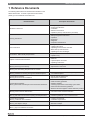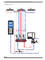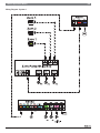
1
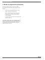
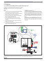
Applications Manual
Gas condensing boiler
WARNING!
Improper installation, adjustment, alteration, service or maintenance
can cause injury, loss of life or property damage. Refer to the
installation and operating manuals. For assistance or additional
information, consult a trained and certified installer, service agency
or the gas supplier.
CAUTION!
The installation and operating manuals are part of the documentation
that is delivered to the installation's operator. Go through the
information in this manual with the owner/operator and make sure that
he or she is familiar with the appliance and its operation.
NOTICE!
In the Commonwealth of Massachusetts this boiler must be installed
by a licensed Plumber or Gas Fitter.
Logamax plus GB142
2 |
Technical specifications are subject to change without prior notice
GB142 Applications Manual
Logamax plus GB142 applications manual | 01.2012
|3
GB142 Applications Manual
Table of Contents
1 Reference Documents
4
2 Boiler Components & Controls
5
2.1 Periphery
6
2.2 Low Loss Header (LLH)
7
2.3 AM10 Outdoor Reset Modulating Boiler Control
9
2.4 RC35 Room Controller and User Interface
13
2.5 0-10V BMS Interface & Common Fault Module EM10
20
2.6 MCM10 Multi Cascade Module
21
3 Sample Applications
25
Legend
26
3.1 System 1: Single boiler with outdoor reset, multiple
heating zones with zone pumps and DHW
27
3.2 System 2: Single boiler with outdoor reset, multiple
heating zones with zone relays and DHW
31
3.3 System 3: Single boiler with RC35, one heating zone,
WM10 and DHW priority
35
3.4 System 4: Single boiler with RC35, WM10, SM10,
one heating zone, & solar thermal DHW
39
3.5 System 5: Multi-boiler Cascade
43
Appendix
47
Appendix 1 - Single boiler with 0-10V heat demand input
48
Appendix 2 - Multi-boiler cascade with 0-10V heat
demand input
50
Appendix 3 - Adding DHW priority to a multi-boiler
cascade
52
Logamax plus GB142 applications manual | 01.2012
Technical specifications are subject to change without prior notice
4 |
GB142 Applications Manual
1 Reference Documents
The following table references all related documentation to the
GB142 series boiler. To obtain copies of these documents,
please go to our website at www.buderus.us.
Document Name
Description Of Contents
Installation Instructions
•
•
•
•
•
Safety and general instructions
Product specifications
Installation
Electrical connections
Operation (start-up and shut down procedure)
Servicing Instructions
•
•
•
•
•
•
Product description
Safety and general instructions
Operation
Symptoms
Diagnosis
Inspection / Maintenance
User‘s Instructions
•
•
•
•
•
Safety information
Lighting instructions
Operating the BC10 basic controller
Boiler start-up and shut down
Operating and error messages
Record Book - Water Quality Requirements
• Requirements
• Operator‘s log
Propane Conversion Kit Instructions
•
•
•
•
Technical Service Bulletin:
TBG-03_Removing Fan Assembly
• Service manual supplement
• Replacement instructions
Technical Service Bulletin:
TBG-04_Flue Gas Venting Requirements for Canada
• ULC S636 venting standard for Canada
Technical Service Bulletin:
TBG-05_Guidelines for Venting Through Unconditioned Space
• Installation requirements for venting through
unconditioned space
Technical Service Bulletin:
TBG-06_Burner Removal & Installation
• Service manual supplement
• Replacement instructions
Technical Service Bulletin:
TBG-07_Boiler Water Chemistry & Freeze Prevention Guidelines
•
•
•
•
•
•
Technical Service Bulletin:
TBG-08_Pressure Sensor Maintenance
• Problem statement and cause
• Corrective action and work instruction
Technical Service Bulletin:
TBG-10_Side Wall Vent Termination Spacing for Multiple Boilers
• Clearance guidelines - Stainless Steel concentric vents
• Clearance guidelines - PVC concentric vents
Technical Service Bulletin:
TBG-22_Condensate Tee Installation
• Location requirements
• Installation requirements
Technical Service Bulletin:
TBG-24_Vent Adaptor Change
• Notification of adaptor release
• Benefits of adaptor
Technical Service Bulletin:
TBG-27_High Limiit Validation Procedure
• High limit test procedure
Safety considerations
Parts list
Liquid Propane conversion
Operating instructions
Recommended steps for commissioning boiler
Water chemistry guidelines
Dielectric isolation
Cleaning requirements / Eliminating system leaks
Aluminum safe anti-freeze guidelines
Buderus selected suppliers of water treatment products
Table 1
Technical specifications are subject to change without prior notice
Logamax plus GB142 applications manual | 01.2012
GB142 Applications Manual
|5
2 Boiler Components & Controls
This chapter outlines the various components available
with the GB142 series boiler along with the following control
options:
•
AM10 - Outdoor Reset Modulating Boiler Control
•
MCM10 - Multi-boiler Cascade Module
•
RC35 - Energy Management System (EMS) with
Outdoor Reset, Room Reset, Zoning and Solar
Thermal capabilities
•
Logamatic 4000 Control System (see Logamatic 4000
Applications Manual)
This manual outlines the most common applications available
using these components and controls. These application
sections contain diagrams of preferred piping with associated
wiring diagrams and controller programming, along with
additional important information.
Logamax plus GB142 applications manual | 01.2012
Technical specifications are subject to change without prior notice
6 |
GB142 Applications Manual
2.1 Periphery
2.1.1 Low Water Cut-off (LWCO) and External Manual Reset High Limit
National or local code may require the installation of an external
Low Water Cut-Off (LWCO) and/or an External Manual Reset
High Limit.
Notes:
1. Contractor to furnish and install LWCO and Manual Reset
High Limit devices as required by local codes.
2.
Do not install any type of valve or check valve in between
boiler and LWCO or Manual Reset High Limit.
3.
Refer to the manufacturer’s instructions when installing
LWCO and Manual Reset High Limit.
4.
LWCO is installed external to the boiler and must
be located above the highest point of the boiler heat
exchanger.
5.
Manual Reset High Limit remote sensing bulb must be
located in the boiler supply.
6.
In a cascade each boiler must be equipped with its own
LWCO and Manual Reset High Limit.
Installation instructions (Fig. 1):
At the back of the boiler manifold remove the 1” plug and
connect a 1” Tee. At the horizontal end connect a 1” well for
the Manual Reset High Limit probe. At the vertical connector
of the Tee, install a 1” stand pipe that reaches above the
highest point of the boiler heat exchanger. Install a second
Tee with an automatic air vent at the top and a LWCO just
below.
Wire the LWCO and the Manual Reset High Limit normally
closed dry contacts in series with EV pins 1 and 2 on the
boiler, which will shut off the burner when the connection is
interrupted.
Fig. 1 Low Water Cutoff views
NOTE: Power supply to LWCO and external high limit not shown for clarity. Follow manufacturer’s instructions.
Technical specifications are subject to change without prior notice
Logamax plus GB142 applications manual | 01.2012
|7
GB142 Applications Manual
In the system under flowing can result in too great a delta T,
resulting in considerable heat being shed in the beginning of
the loop and insufficient heat left for the remainder of the loop.
2.2 Low Loss Header (LLH)
2.2.1 General Information
Installation of a LLH however requires a pump on the boiler
side and one on the system side.
As their flow rates are typically low, some manufacturers design
a LLH to include an air eliminator and dirt separator.
GB142
GB142
A typical example is a system with low mass boilers and
multiple zones with zone pumps. The LLH ensures a constant
flow rate through the boilers independently of how many
zones are calling and independently of the flow rate in the
system loop. It prevents pumps from working against each
other, resulting in balanced flows, even heat distribution, and
reduction of potential noise.
Fig. 2 Two Boiler System with Low Loss Header
Supply
Supply
BOILER
SYSTEM
Return
Return
Fig. 3 Low Loss Header Overview
Modern compact wall hung gas appliances are often equipped
with boiler controlled modulating pumps, some of which are
also used for making DHW. These pumps are operating in ways
that optimize boiler efficiency and longevity, but are not suitable
for supplying the system at the same time. As a result the
system must be set up with hydraulic separation between the
primary and secondary sides.
A LLH is nothing more than a large pipe, installed between
the heat sources and the system. It is used in single and multi
boiler installations of appliances with small water volumes to
independently control the flow of water in the boiler loop and
the system loop.
When the circulating volumes between boiler loop and system
loop differs greatly, a LLH can help avoid over flowing or under
flowing one or the other. Over flowing can lead to noise and
erosion in the piping, and can be identified by a boiler or system
not coming up to temperature, or by a narrow delta T. Under
flowing means that the heat is not being transported away from
the boiler, causing it to bounce off the high limit.
Logamax plus GB142 applications manual | 01.2012
Technical specifications are subject to change without prior notice
8 |
GB142 Applications Manual
Possible scenarios of the LLH:
V₁
V₂
R₁
R₂
Both primary and secondary flow rates
are identical.
V₁
R₁
V₂
R₂
The boiler flow rate is greater than the
system flow rate and hot supply water
is returning to the boiler.
V₁
V₂
R₁
R₂
The system flow rate is greater than the
boiler flow rate and cold return water is sent
back out to the system.
Fig. 4 Three possible flow patterns with a LLH
A LLH is typically equipped with a well for a system strategy
sensor to measure supply water temperature. If this is not the
case the system supply temperature sensor should be strapped
onto the system supply pipe coming off the LLH.
A LLH is oversized to a point that it can handle the maximum
possible flow rates on either side without significant pressure
drop.
In the center of the LLH is the point of equilibrium and zero
pressure. It allows for a variety of flow rates to occur on both
sides of the system without influencing the other side.
A common case from retrofit applications: The system pumps
are too strong and remove more water from the LLH than
delivered by the boiler. With the consequence that none of
the zones gets up to temperature. Required measure: reduce
system flow rates.
For system redundancy, energy optimization, or combination
of different fuel types, different boiler types or models may be
combined in systems. Based on the load this allows turning
off complete appliances resulting in higher efficiencies of the
remaining system.
When a larger heat demand occurs additional boilers can be
enabled one by one. The changing flow rates are balanced by
the LLH and all boilers and zones in operation are continued to
be supplied with the necessary volumes.
Example:
Old boiler output 480 MBH (140 kW)
New boiler output: 340 MBH (100 kW)
The new system requires a system flow rate of 19 gpm (4300
liters/hr) at 36°F (20°C) delta T.
As older systems are typically equipped with oversized pumps,
the retrofit system can be expected to use pumps that may
be half the size of the old ones. In this case only a LLH allows
balancing of the primary and secondary flow rates.
It is recommended to use multi speed or ECM pumps.
Sizing a Low Loss Header
Size the pumps and LLH by the greater of the two volumes that
is circulating: boiler circuit or system circuit.
.
Note: It is recommended to set the minimum delta T between
boiler supply and boiler return to 20 to 25°F (10 to 15°C) by
adjusting the speed of the circulator or installing flow setters.
For sizing a LLH at maximum throughput the flow rate should
not exceed 0.67 feet/second (0,2 m/s). This makes the LLH
the area of slowest velocity and allows it to be used as an air
separator and dirt separator.
Over sizing a LLH however does not have negative
consequences on the system. In fact a buffer tank can be used
instead of a LLH.
To ensure efficiency while also providing redundancy, each
boiler must have its own boiler pump.
In particular when an existing system is retrofit with a new boiler
it is necessary to evaluate the boiler and system flow rates. A
reduction of boiler output can in many cases reach 40% and
completely change system hydraulics.
Technical specifications are subject to change without prior notice
Logamax plus GB142 applications manual | 01.2012
|9
GB142 Applications Manual
2.3 AM10 Outdoor Reset Modulating Boiler Control
Product Description
The AM10 is a modulating outdoor reset control for Buderus
boilers equipped with the EMS bus. It sets the supply water
temperature based on outdoor temperature. The boiler fires,
runs and modulates based on the information received from the
AM10, taking into consideration the delta T between supply and
return.
An ON/OFF signal from a third party room thermostat or
zone controller (not included) is used to communicate a heat
demand. The AM10 offers warm weather shutdown (WWSD)
when the outdoor temperature rises above a custom setable
temperature (default: 70°F (21°C)).
To control and stage multiple boilers, combine the AM10 with an
MCM10 cascade module.
Outdoor reset
Outdoor reset is a way to economically control space heating
based on the outdoor temperature. It functions based on the
fact that the colder the weather the greater the heat loss of a
structure, and the higher the supply water temperature needed
to heat the house. On a warmer day with smaller heat loss a
lower water temperature will be able to heat the house. This has
several advantages:
Fig. 5 AM10 Modulating Control
1. Save fuel by running the boiler at lower temperatures
which reduces the heat going up the chimney.
2. Lower water temperatures allow taking advantage of the
energy trapped in the flue gases (latent heat) in a
condensing appliance.
3. Added comfort because temperature changes are not felt
with lower water temperatures running constantly.
To achieve these goals the reset curve must be properly
adjusted to match the application and the heat loss of
the structure. The reset curve tells the boiler what water
temperature is needed at a certain outdoor temperature.
Outdoor reset is the preferred control when using multiple
zones, as the boiler supply water temperature is not dictated by
a master or largest zone, but solely based on the heat loss of
the structure.
Logamax plus GB142 applications manual | 01.2012
Technical specifications are subject to change without prior notice
10 |
GB142 Applications Manual
Heating curve
The AM10 has a built in linear heating curve that sets the supply
water temperature in relation to the outdoor temperature.
Top of heating curve represents the water temperature at 14°F
(-10°C) outdoor temperature. Based on type of heating system
different water temperatures are recommended for bottom of
heating curve. The boiler follows the heating curve in the AM10
up to the maximum supply water temperature set on the boiler
dial which works as a high limit (in cascades always set to
AUT). In addition the warm weather shut down (WWSD) turns
the heating system off when the temperature outdoors rises
above a certain value.
Heating curve chart in Degrees Fahrenheit:
200
194
190
Boiler High Limit
Radiant Floor
Panel
Radiators
Baseboard
Hydro Air
Cast Iron Radiators
180
170
Supply Water Temperature [°F]
160
150
140
130
120
Use high limit to prevent
radiant floor damage
from overheating.
(not in cascades)
110
100
90
80
Upper Reference point
Heating curve base point
70
WWSD factory default
60
80
70
60
50
40
30
Outdoor Temperature [°F]
20
14
10
0
-10
Fig. 6 Heating curve chart in Degrees Fahrenheit
Outdoor
Temperature
(°F)
Radiant Floor
Panel
Radiators
Cast Iron
Radiators
Baseboard
Hydro Air
0
120
176
162
184
190
14
120
160
150
167
182
68
86
100
100
100
150
70
85
98
98
98
148
Technical specifications are subject to change without prior notice
Logamax plus GB142 applications manual | 01.2012
| 11
GB142 Applications Manual
Heating curve chart in Degrees Celsius:
100
Boiler High Limit
90
90
Radiant Floor
Panel
Radiators
Baseboard
Hydro Air
Cast Iron Radiators
80
Supply Water Temperature [°C]
70
60
50
Use high limit to prevent
radiant floor damage
from overheating.
(not in cascades)
40
30
20
Heating curve base point
10
Upper Reference point
WWSD factory default
0
25
20
10
15
0
5
Outdoor Temperature [°C]
-5
-10
-15
-20
Fig.7 Heating curve chart in Degrees Celsius
(°C)
Outdoor
Temperature
Radiant Floor
Panel
Radiators
Cast Iron
Radiators
Baseboard
Hydro Air
-18
49
80
72
84
88
-10
49
71
66
75
83
20
30
38
38
38
65
21
29
37
37
37
64
Logamax plus GB142 applications manual | 01.2012
Technical specifications are subject to change without prior notice
12 |
GB142 Applications Manual
WWSD
Single Boiler Control
Warm weather shut down (WWSD) temperature is factory set
for 70°F (21°C). If the outdoor temperature rises above this
setting, the boiler will be turned off except for generating DHW.
The value can be adjusted between 32°F (0°C) and 86°F
(30°C).
To equip a single GB142 boiler with outdoor reset control, the
following items are recommended: (not included)
•
ON/OFF thermostat for each heating zone
•
Pump relay or zone valve panel according to the number
of zones
•
Low and high voltage wiring, 24VAC transformer, etc.
Mounting of the AM10
Wiring Details:
If there are multiple zones, wire all closed contacts to the AM10
so that each call for heat produces a heat demand.
The recommended mounting locations are either on the wall
next to the boiler or on the boiler jacket. A mounting bracket is
included with the controller.
Positioning the outdoor sensor
For best performance the outdoor sensor is to be positioned
at a location where it is not influenced by sunlight. Mount only
on a North facing wall of the building, and at least 1 foot above
snow line. Keep the sensor away from heat sources such as a
dryer, water heater, or boiler vents, windows, etc.
Set the BC10 central heating dial to automatic (AUT), unless
the system consists exclusively of low temperature radiant,
where the central heating dial can be used as a high limit
protection. In cascades the AUT setting is required.
Note: Do not install an RC10, EM10, or RC35 when using this
configuration as these devices do not coexist with the
AM10. For multi-boiler systems add the MCM10 cascade
module between the AM10 and the boilers.
to
Multi-Zone Relay Box
Fig. 8 Installation example with zone relay box
Technical specifications are subject to change without prior notice
Logamax plus GB142 applications manual | 01.2012
| 13
GB142 Applications Manual
2.4 RC35 Room Controller and User Interface
The RC35 is an outdoor reset based heating system control
with room influence and optional solar thermal DHW generation
capability.
2.4.2 Overview
2.4.1 Features and benefits
•
Outdoor reset
•
Room reset or room influence
•
Setback options
- Room setback
- Night setback
- Outdoor setback
- Shut-down
•
8 pre-loaded time programs with option to create custom
program
•
System Efficiency
- Microprocessor coordinates boiler operation to ensure
maximum comfort with optimized energy usage
- Adjustable warm weather shut down (WWSD)
- Room influence setting to prevent zone overheating
•
Monitoring
- Monitoring of system data including operating hours and
burner starts
- Solar thermal gain monitoring in combination with SM10
module
•
User friendly
- Easy to use due to LCD display with full text
- Relay testing for start-up, commissioning and
troubleshooting to verify proper wiring
•
Service information
- Service and diagnostic system simplifies troubleshooting
- Maintenance reminder feature alerts the operator when
servicing is due
•
Modular structure of the control system allows customizing
for many applications
- Up to 4 heating zones (3 mixed, 1 unmixed) using 3
MM10 - Mixing Modules
- Solar thermal integration for DHW generation using
SM10 - Solar Thermal Module
- Integration of a low loss header using WM10 - Low Loss
Header Module
- Cascade up to 16 boilers using up to 4 MCM10 - MultiBoiler Cascade Modules.
- DHW preparation including control of a DHW
recirculation pump
Logamax plus GB142 applications manual | 01.2012
1
THU 06.07. 2011 4:45pm
Control features
Room
2
71.9 °F
3
4
11 10
9
8
7
6
5
Fig.9 Description of the RC35 room control
1:
2:
3:
4:
5:
6:
7:
8:
9:
10:
11:
Automatic mode (switching program)
Continuous heating (day temperature)
Permanently reduced (night temperature)
DHW single charge button
Change temperature temporary
Back
Show data
Set day or night temperature
Set current date
Set current time
Open User menu
Technical specifications are subject to change without prior notice
14 |
GB142 Applications Manual
2.4.3 RC35 room control programming aspects
User menu:
User Menu
THU 06.07. 2011 4:45pm
Room
71.9 °F
Standard display
Modes of operation
Switching program
Warm weather shut down (WWSD)
DHW temperature
Vacation
Party program
Pause function
Thermal desinfection
Service menu:
+
THU 06.07. 2011 4:45pm
Room
71.9 °F
+
Service Menu
Quick operation
Settings
Diagnosis
Servicing
Reset
Technical specifications are subject to change without prior notice
Logamax plus GB142 applications manual | 01.2012
| 15
GB142 Applications Manual
2.4.4 RC35 wiring diagrams
The RC35 user interface can be installed in a reference room to
utilize the internal thermostat for room reset, or in a dedicated
bracket in the boiler if room influence is not required.
Mounting the RC35 in the room and utilizing its
internal room sensor:
Mounting the RC35 in the room and utilizing a remote
room sensor (part number: 5 993 226):
Fig.10 RC35 wiring using its internal room sensor
Fig.11 RC35 wiring using its remote room sensor
2.4.5 EMS modules for RC35
Single Mixed Heating Zone Module MM10
This module is needed to operate a mixed heating zone pump
and motorized mixing valve. The RC35 can control up to 3
MM10 modules per system.
Features of the MM10:
• Room reset, outdoor reset, outdoor reset with room influence.
• Keyed and color coded connecting plugs
• Sends a quantified heat demand to the boiler
• Mounting: In the boiler or on the wall
• LED indicator for mode of operation
• Up to 3 modules per heating system
• Uses the RC35 user interface
• 120V supply
• Each module allows it’s own temperature zone and timer
program
• Selectable set back options for each individual zone
• Anti-freeze protection per zone
• Pump anti-seize function
• Input:
1 x Heating Zone Supply Sensor
• Outputs: 1 x Heating Zone Pump 120V
1 x 3-way Floating Mixing Valve 120
Logamax plus GB142 applications manual | 01.2012
Fig.12 Single Mixed Heating Zone Module MM10
Technical specifications are subject to change without prior notice
16 |
GB142 Applications Manual
Unmixed Heating Zone & Low Loss Header Module
WM10
The WM10 has two functions:
1.
Runs one unmixed heating zone
2.
Controls the hydraulic separation between the boiler loop
and system loop in systems with a low loss header (LLH)
Features of the WM10:
• In an unmixed heating zone a separate timer program can
be selected.
• Keyed and color coded connecting plugs
• Communication with EMS boiler-data bus
• Mounting: In the boiler or on the wall
• LED indicator for mode of operation
• 1 module per heating system
• 120V supply
• Input: 1 x Heating Zone Supply Sensor or System Supply
Sensor
• Output: 1 x Heating Zone Pump 120V or System Pump 120V
Fig.13 Unmixed heating zone and Low loss header Module
WM10
Solar Thermal DHW Module SM10
The SM10 Module integrates a Solar Thermal DHW system with
an EMS boiler system which provides significant energy savings
for DHW generation. The integrated system knows when solar
energy is available and reduces boiler run time and boiler starts.
Features of the SM10:
•
•
•
•
•
•
•
•
Keyed and in color coded connecting plugs
Communication with EMS boiler-data bus
Mounting: In the boiler or on the wall
LED indicator for mode of operation
1 module in a heating system
Solar pump modulation 20-100% to maximize solar gain
120V supply
Input: 1 x Collector Sensor
1 x Solar Tank Sensor (Bottom)
• Outputs: 1 x Solar Thermal Pump 120V
Technical specifications are subject to change without prior notice
Fig.14 Solar Thermal DHW Module SM10
Logamax plus GB142 applications manual | 01.2012
| 17
GB142 Applications Manual
2.4.6 Mixing Module MM10 Wiring Diagram
120
L
Fuse
5 AT
- + - +
14AWG
120 V 60Hz
14AWG,
Max. 5A
14AWG,
Max. 5A
System
Main power
18AWG
18AWG
18AWG
supply
120 V 60Hz
2)
Valve actuator
motor
run time:
Notes:
Polarity matters on EMS/RC bus: Connect 1 to 1 and 2 to 2.
Implement the installation, fuse protection, main isolator,
emergency stop switches and safety measures in accordance with
local/national regulations.
Warning! Ground yel/grn must not be used as a control line.
Ensure phases are connected correctly.
1) Requires 120V mixing valve with 3-point floating actuator.
Maximum current: 5A
2) Hot: increase hot water delivery to zone
Cold: decrease hot water delivery to zone
Logamax plus GB142 applications manual | 01.2012
Technical specifications are subject to change without prior notice
18 |
GB142 Applications Manual
2.4.7 WM10 - System or Low Loss Header
Module Wiring Diagram
120
L
- + - +
14AWG
120 V 60Hz
14AWG,
Max.5A
18AWG
Main power
120 V 60Hz
18AWG
18AWG
zone
low loss
header
Notes:
Polarity matters on EMS/RC bus: Connect 1 to 1 and 2 to 2.
Implement the installation, fuse protection, main isolator,
emergency stop switches and safety measures in accordance with
local/national regulations.
Warning! Ground yel/grn must not be used as a control line.
Ensure phases are connected correctly.
Technical specifications are subject to change without prior notice
Logamax plus GB142 applications manual | 01.2012
| 19
GB142 Applications Manual
2.4.8 Solar Module SM10 Wiring Diagram
120
L
- + - +
14AWG
120 V 60Hz
18AWG
14AWG,
Max. 1A
18AWG
18AWG
18AWG
Main power
120 V 60Hz
tank
Notes:
Polarity matters on EMS/RC bus: Connect 1 to 1 and 2 to 2.
Implement the installation, fuse protection, main isolator, emergency
stop switches and safety measures in accordance with local/national
regulations.
Warning! Ground yel/grn must not be used as a control line.
Ensure phases are connected correctly.
Logamax plus GB142 applications manual | 01.2012
Technical specifications are subject to change without prior notice
20 |
GB142 Applications Manual
2.5 0-10V BMS Interface & Common Fault Module EM10
The EM10 Module allows interfacing a single boiler with a
Building Management System (BMS) for temperature or output
setpoint control. The EM10 also has a dry set of N/O and N/C
contacts that can be used to trigger a system alarm.
Features of the EM10:
• Run single boiler based on BMS input 0-10V signal for
temperature or output setpoint control
• Input: 0-10V
• Common fault dry contact output NO/NC
• 120V supply
Fig.15 EM10 0-10V BMS Interface Module
Technical specifications are subject to change without prior notice
Logamax plus GB142 applications manual | 01.2012
| 21
GB142 Applications Manual
2.6 MCM10 Multi Cascade Module
The MCM10 - Multi Cascade Module allows running and
staging multiple boilers in a cascade system.
Each MCM10 controls up to 4 boilers, and with 4 modules in a
system, up to 16 boilers can be controlled.
The MCM10 can only be used with boilers that have the EMSBUS (UBA3, UBA3.5).
Boilers of any size can be connected in the cascade system as
long as they are EMS-BUS compatible.
2.6.1 System Integration
The MCM10 stages the boilers within the cascade system
based on a heat demand from one of the following the following
sources:
•
•
•
•
0-10V BMS input directly to the MCM10
W-A dry contact input directly to the MCM10
AM10 outdoor reset controller with dry contact input
RC35 energy management system
The MCM10 controls the system supply temperature, which
requires a system supply temperature sensor strategically
placed.
Fig.16 Multi Cascade Module (MCM10)
Logamax plus GB142 applications manual | 01.2012
Technical specifications are subject to change without prior notice
22 |
GB142 Applications Manual
2.6.2 MCM10 LED Functions
MCM10 Front Panel
1
2
GRN
1
GRN
5
Off: No power / internal error MCM10
Off: Pump off
On: Pump on
RED
!
GRN
4
Off: No fault present
Blinking: System fault present (example: system, switching contact activated.
Off: No communication
On: Communication between MCM10 and the previous MCM10.
Communication between MCM10 and a Heating Controller (e.g. RC35)
GRN
5
4
On: Standard operation
2
3
3
Off: No heat demand, boiler on stand by
On: Heat demand, boiler in operation
Fig.17 MCM10 LED functions
Technical specifications are subject to change without prior notice
Logamax plus GB142 applications manual | 01.2012
| 23
GB142 Applications Manual
2.6.3 MCM10 Electrical Connection Diagram
YEL
YEL
120V
120V
PE N L
PE N L
Input Mains
Supply
GRN
PE N L NO C NC
RED
WHT
GRN
2
3
4
System
supply
temperature
sensor
- use only in
combination
with AM10
Outdoor
Temperature
Sensor
- use only in
combination
with RC35
GRY
BLK
13
14
Communication
between this
MCM10 and
previous
MCM10
15
16
Communication
between this
MCM10 and
following
MCM10
120V
PE N L
PE N L NO C NC
0 .... 10V
5
6
7
8
9
+
10
WHT
17
18
Boiler 1
19
Line voltage
11
WHT
20 21
Boiler 2
3
4
5
6
7
8
9
+
10
11
12 13
14
15
16 17
18
19
20 21
22
23
24
Low voltage
12
MM10, WM10,
SM10 &
continue to
modulating
control AM10
or RC35
Dry contact 0 - 10 Volt
External
heat demand heat
safety
disconnect input
demand
(safeguard)
input
WHT
2
ORG
0 .... 10V
1
120V
PE N L
1
BLU
Printed
Circuit
Board
Jumper for
output power
or temperature
control with
0-10V
input 9/10.
Alarm output
dry contact
NO/NC
System
Pump
- use only
with AM10.
Output Mains
Supply to
following
MCM10,
MM10, SM10
WM10
BRN
120
VAC
RED
22
Boiler 3
WHT
23
24
Boiler 4
Fig.18 MCM10 connection diagram
Logamax plus GB142 applications manual | 01.2012
Technical specifications are subject to change without prior notice
24 |
GB142 Applications Manual
2.6.4 MCM10 Configuration Options
Configuration
GB142
GB142
GB142
Description
Controls
0-10V
heat
demand
input
from BMS
up to 16
GB142
up to 4 MCM10
GB142
GB142
GB142
dry
contact
heat
demand
input
up to 16
GB142
up to 4 MCM10
GB142
GB142
GB142
up to 16
GB142
up to 4 MCM10
AM10
Buderus
AUT
GB142
GB142
GB142
up to 4
GB142
1 heat circuit
MCM10
GB142
GB142
GB142
up to 8
GB142
1 mixed and
1 unmixed
heating zones
GB142
GB142
AUT
up to 12
GB142
2 mixed and
1 unmixed
heating zones
GB142
GB142
RC35
WM10
MM10
WM10
2x MM10
WM10
3x MM10
Buderus
AUT
3x MCM10
GB142
WM10
Buderus
2x MCM10
GB142
RC35
up to 16
GB142
3 mixed and
1 unmixed
heating zones
RC35
Buderus
AUT
4x MCM10
RC35
Fig.19 MCM10 Configuration Options
Technical specifications are subject to change without prior notice
Logamax plus GB142 applications manual | 01.2012
| 25
GB142 Applications Manual
3 Sample Applications
Legend
26
3.1 System 1: Single boiler with outdoor reset,
multiple heating zones with zone pumps
and DHW
27
3.2 System 2: Single boiler with outdoor reset,
multiple heating zones with zone relays
and DHW
31
3.3 System 3: Single boiler with RC35, one
heating zone, WM10 and DHW priority
35
3.4 System 4: Single boiler with RC35, WM10,
SM10, one heating zone, & solar thermal
DHW
39
3.5 System 5: Multi-boiler Cascade
43
Logamax plus GB142 applications manual | 01.2012
Technical specifications are subject to change without prior notice
26 |
GB142 Applications Manual
Legend
High temperature zone
(e.g. baseboard)
Solar pump station
Distribution manifold
Return pipe
Supply pipe
Purge station
Solar thermal collector array
Expansion tank and PRV for
solar thermal system
GB142 boiler with LLH
Temperature gauge
Indirect fired solar tank
Outdoor temperature sensor
Indirect fired DHW tank
Room thermostat
Temperature sensor
RC35 controller
Pump
MCM10 multiboiler cascade
module
GB142
T
Feed line and expansion tank
with air vent
Communication line
Zone valve
Sensor line
Check valve
Low voltage line
(maximum 24V)
Two way shut off valve
Line voltage line
(120V)
Safety relief valve
Fig.20 Legend
NOTICE: All drawings in this manual are conceptual in nature and only depict components relevant for the systems shown. It is the
installer’s responsibility to know national and local code and install safety devices as required. Install and size peripheral devices such
as air purge, expansion vessel, feeder valve, mud separator, shutoff valves, etc. per best installation practices. Contact Buderus with
installation related questions.
Technical specifications are subject to change without prior notice
Logamax plus GB142 applications manual | 01.2012
| 27
GB142 Applications Manual
3.1 System 1: Single boiler with outdoor reset, multiple heating zones
with zone pumps and DHW
Summary:
Additional instructions:
Single boiler supplying multiple heating zones equipped
with 3rd party thermostats and zone pumps. This system is
recommended if pressure drops in individual zones are too
great to be served by a single system pump (see system 2).
See manufacturer’s installation and operating instructions for
details on 3rd party components.
•
High efficiency outdoor reset controlled system based on
heat loss of the structure
•
Outdoor reset for system supply water temperature
If the DHW sensor in the tank reports a call for DHW, the boiler
will ramp up the supply temperature according to the DHW
setting overriding the outdoor reset heating curve.
•
Zone pumps are controlled by 3rd party relay panel and
individual room thermostats
•
Optional DHW tank loading with or witho ut priority
The system shown generates DHW with priority over space
heating.
The boiler has DHW priority built in. Use the DHW sensor with
the DHW tank and select the DHW temperature using the boiler
dial. During a DHW call the PS tank loading pump will run and
the PK boiler pump will be off. Once DHW is satisfied the boiler
will return to space heating.
In detail:
The AM10 outdoor reset controller receives a heat demand from
the zone thermostats via a closed contact and computes the
system supply water temperature based on information from the
outdoor sensor and the heating curve.
If DHW is not installed, set the DHW dial to OFF.
Applications include multiple zones at the same temperature,
or zones at different temperatures if thermostatic or externally
controlled motorized mixing valves are used.
The AM10 provides warm weather shutdown.
The modulating boiler strives to run at low fire for the longest
time possible where efficiency is at its highest.
DHW is heated based on the signal from the DHW tank sensor
FW. DHW is generated in parallel with space heating if both are
calling simultaneously. For faster DHW recovery, install a relay
that disables zone circulators while the tank loading pump is
activated. Alternatively a zone relay panel with DHW priority can
also be used.
The low loss header decouples the boiler loop from the system
loop.
Required components:
• GB142 boiler
• AM10 controller (incl. with GB142)
• PH zone circulators
• PS DHW tank loading circulator
• ECM pumps (low energy or constant pressure pumps) are
recommended for constant flow rate and additional energy
savings.
• DHW tank
• Multi zone pump relay panel with/without DHW priority
• PS DHW tank loading circulator
• Zone thermostat per room/zone
Logamax plus GB142 applications manual | 01.2012
Technical specifications are subject to change without prior notice
28 |
GB142 Applications Manual
Piping Diagram - System 1
Technical specifications are subject to change without prior notice
Logamax plus GB142 applications manual | 01.2012
GB142 Applications Manual
| 29
Wiring Diagram - System 1
Logamax plus GB142 applications manual | 01.2012
Technical specifications are subject to change without prior notice
30 |
GB142 Applications Manual
Programming - System 1
•
When powering up the AM10 the current outdoor
temperature is displayed (Fig. 21).
•
Press the mode key to switch to the next menu item. On
the screen a block will indicate the current step from 1
through 5.
•
The second menu item is the current supply temperature
computed based on the current outdoor temperature
(Fig. 22).
•
Press the mode key to switch to the next menu item.
•
Define the heating curve by entering two distinct set points.
(A) Supply water temperature at 14°F (-10°C) outdoor
temperature (Fig. 23), and by pressing the mode key
again, (B) supply water temperature at 68°F (20°C) outdoor
temperature (Fig. 24).
•
Press the mode key to switch to the warm weather shut
down (WWSD) temperature (Fig. 25). If the outdoor
temperature rises above this value space heating will stop.
•
Pressing the mode key again will return the display to the
current outdoor temperature (Fig. 21).
Range
Factory Default
Supply water temperature at 14°F:
68 - 194 °F
167 °F
Supply water temperature at 68°F:
68 - 194 °F
86 °F
Warm weather shut down temperature:
32 - 86 °F
70 °F
Fig.21 Default display: Current outdoor temperature
Fig.22 Current target supply temperature
See also chapter 2.3 for additional information on the AM10.
Fig.23 Heating curve upper value (14 °F)
Fig.24 Heating curve lower value (68 °F)
Fig.25 Warm weather shut down temperature
Technical specifications are subject to change without prior notice
Logamax plus GB142 applications manual | 01.2012
| 31
GB142 Applications Manual
3.2 System 2: Single boiler with outdoor reset, multiple heating zones
with zone relays and DHW
Summary:
Additional instructions:
Single boiler system with a system pump supplying multiple
heating zones with 3rd party thermostats and zone valves.
Use this design for systems with smaller pressure drops, e.g.
baseboard and panel radiators, compared to system 1 which
better handles radiant floors with high pressure drops that
require a separate pump for each zone.
See manufacturer’s installation and operating instructions for
details on 3rd party components.
•
Outdoor reset for system supply water temperature
•
Zone valves are controlled by 3rd party relay panel
•
•
DHW loading with or without priority
High efficiency outdoor reset controlled system based on
heat loss of the structure
•
Automatic warm weather shut down (WWSD)
In detail:
The system shown generates DHW with priority over space
heating.
If the DHW sensor in the tank reports a call for DHW, the boiler
will ramp up the supply temperature according to the DHW
setting overriding the outdoor reset heating curve.
The boiler has DHW priority built in. Use the DHW sensor with
the DHW tank and select the DHW temperature using the boiler
dial. During a DHW call the PS tank loading pump will run and
the PK boiler pump will be off. Once DHW is satisfied the boiler
will return to space heating.
If DHW is not installed, set the DHW dial to OFF.
The AM10 outdoor reset controller receives a heat demand
via a closed contact and computes the system supply water
temperature based on information from the outdoor sensor and
the heating curve.
Applications include multiple zones at the same temperature,
or zones at different temperatures if thermostatic or externally
controlled motorized mixing valves are used.
The AM10 provides warm weather shutdown.
The modulating boiler strives to run at low fire for the longest
time possible where efficiency is at its highest.
DHW is heated based on the signal from the DHW tank sensor
FW. DHW is generated in parallel with space heating if both are
calling simultaneously. For faster DHW recovery, install a relay
that disables the zone circulator while the tank loading pump is
activated. Alternatively a zone relay panel with DHW priority can
also be used.
The low loss header decouples the boiler loop from the system
loop.
Required components:
•
GB142 boiler
•
AM10 controller (incl. with GB142)
•
Multi zone valve relay panel with/without DHW priority.
•
PH system circulator
•
PS DHW tank loading circulator
•
ECM pumps (low energy or constant pressure pumps) are
recommended for constant flow rate and additional energy
savings.
•
Zone valves
•
Room thermostats
Logamax plus GB142 applications manual | 01.2012
Technical specifications are subject to change without prior notice
32 |
GB142 Applications Manual
Piping Diagram - System 2
Technical specifications are subject to change without prior notice
Logamax plus GB142 applications manual | 01.2012
GB142 Applications Manual
| 33
Wiring Diagram - System 2
Logamax plus GB142 applications manual | 01.2012
Technical specifications are subject to change without prior notice
34 |
GB142 Applications Manual
Programming - System 2
•
When powering up the AM10 the current outdoor
temperature is displayed (Fig. 26).
•
Press the mode key to switch to the next menu item. On
the screen a block will indicate the current step from 1
through 5.
•
The second menu item is the current supply temperature
computed based on the current outdoor temperature
(Fig. 27).
•
Press the mode key to switch to the next menu item.
•
Define the heating curve by entering two distinct set points.
(A) Supply water temperature at 14°F (-10°C) outdoor
temperature (Fig. 28), and by pressing the mode key
again, (B) supply water temperature at 68°F (20°C) outdoor
temperature (Fig. 29).
•
Press the mode key to switch to the warm weather shut
down (WWSD) temperature (Fig. 30). If the outdoor
temperature rises above this value space heating will stop.
•
Pressing the mode key again will return the display to the
current outdoor temperature (Fig. 26).
Range
Factory Default
Supply water temperature at 14°F:
68 - 194 °F
167 °F
Supply water temperature at 68°F:
68 - 194 °F
86 °F
Warm weather shut down temperature:
32 - 86 °F
70 °F
Fig.26 Default display: Current outdoor temperature
Fig. 27 Current target supply temperature
See also chapter 2.3 for additional information on the AM10.
Fig. 28 Heating curve upper value (14 °F)
Fig. 29 Heating curve lower value (68 °F)
Fig. 30 Warm weather shut down temperature
Technical specifications are subject to change without prior notice
Logamax plus GB142 applications manual | 01.2012
| 35
GB142 Applications Manual
3.3 System 3: Single boiler with RC35, one heating zone, WM10 and
DHW priority
Summary:
Required components:
Ideal setup for large open floor plans, e.g. restaurants,
churches, retail, shop floors, etc.
•
•
•
•
•
GB142 boiler
RC35 controller
WM10 LLH module
PH system circulator
PS DHW tank loading circulator
•
ECM pumps (low energy or constant pressure pumps) are
recommended for constant flow rate and additional energy
savings.
Single boiler system supplying one zone
•
Outdoor reset with room feedback
•
RC35 room sensor and user interface installed in a
reference room for room feedback
•
Zone pump is controlled by the boiler
•
Separate day and night temperature program with multiple
setpoints for the heating zone and DHW separately
•
DHW loading with or without priority
•
Maximum efficiency from outdoor reset based on heat loss
of the structure and maximum comfort from room feedback
•
Upgradable to DHW Solar Thermal (see system 4)
In detail:
The RC35 computes a quantified heat demand for the structure
based on information from the outdoor sensor, its internal room
sensor, and the heating curve. Applications include a high,
medium and low temperature zone (e.g. radiant floor, panel
radiators, baseboard or hydro-air).
Day and night temperatures can be set based on the unique
requirements of the zone and when occupants will be present
and absent.
Additional instructions:
Install the system supply temperature sensor FK after the
system pump in order to be able to detect a defective pump.
Install the DHW tank temperature sensor FW in the tank per the
tank instructions. The RC35 is designed for constant circulation.
Do not combine the RC35 with zone valves or a relay panel.
Control modes
The following control modes are available with the RC35:
•
Outdoor reset (factory default):
The system water temperature is calculated in response
to the outdoor temperature. This temperature is then
delivered to the zones by a constantly operating heating
zone pump. The pump will only shut-down in warm weather
shut down, night setback (shut-down mode only) or DHW
mode (domestic hot water priority only). Install the RC35
unit in the boiler, or in the room with maximum room
influence set to 0 (factory setting).
•
Outdoor reset with room influence:
The RC35 must be installed in a reference room in order
to record the room temperature accurately. The higher the
room influence parameter set the greater its influence on
the heating curve. If maximum room influence is set to 0
(factory setting), room feedback is disabled.
•
Room reset:
With outdoor reset disabled and the RC35 installed in a
reference room the system water temperature is influenced
only by the conditions in the room. Applications include
super insulated structures, or rooms with significant solar
gain, auxiliary heat (wood stove), or similar.
The WM10 module controls the zone pump in constant
circulation which prevents temperature swings and provides
maximum comfort. Low energy pump recommended.
The modulating boiler strives to run at low fire for the longest
time possible where efficiency is at its highest.
DHW is heated according to a customized timer program. DHW
priority over space heating can be enabled or disabled. DHW
single charge button is used to reload the tank during night
mode.
The RC35 user interface come equiped with integrated
room sensor and full text display for easy programming and
operation.
Displays outdoor temperature curve for yesterday and today.
Holiday function allows reduced temperatures during absence
and bringing the space back to temperature in time when
returning home.
Solar Thermal DHW functionality integrated in controls for easy
retrofit (see system 4)
The low loss header decouples the boiler loop from the system
loop.
DHW recirculation pump functionality built in with separate timer
program.
Logamax plus GB142 applications manual | 01.2012
Technical specifications are subject to change without prior notice
36 |
GB142 Applications Manual
Piping Diagram - System 3
Technical specifications are subject to change without prior notice
Logamax plus GB142 applications manual | 01.2012
GB142 Applications Manual
| 37
Wiring Diagram - System 3
Logamax plus GB142 applications manual | 01.2012
Technical specifications are subject to change without prior notice
38 |
GB142 Applications Manual
Programming - System 3
Enter the service level in RC35 control as described in the
Installation and Service instructions or in chapter 2.4.2.
Important parameters:
•
Go to settings, press MENU/OK
•
Turn dial clockwise until Did you install a low loss header
module? appears. Select Yes.
•
Turn dial clockwise until Is heating zone 1 installed
(unmixed heating zone)? appears. Select Yes.
•
Press RETURN and select heating zone 1, press MENU/
OK
•
Turn dial clockwise until Should heating zone 1 be
activated? appears. Select Yes.
•
Turn dial clockwise until Which user interface is assigned
to heating zone 1? appears. Select RC35 if the unit is
mounted in a representative room for room reset or outdoor
reset with room feedback.
Fig.31 RC35 overview
SERVICE MENU
Set up the remainder of the parameters according to the
Installation and Service instructions.
See also chapter 2.4 for additional information on the RC35.
quick operation
settings
diagnosis
servicing
Fig.32 RC35 service menu view
Technical specifications are subject to change without prior notice
Logamax plus GB142 applications manual | 01.2012
| 39
GB142 Applications Manual
3.4 System 4: Single boiler with RC35, WM10, SM10, one heating zone, & solar
thermal DHW
Summary:
Ideal setup for large open floor plans, e.g. restaurants,
churches, retail, shop floors, etc. plus a significant DHW
demand daily. Single boiler system supplying one unmixed
heating zone combined with solar thermal DHW with boiler
backup. This is a proven system that is simple to install, almost
maintenance free, and fully automated.
customized timer program. DHW priority over space heating
can be enabled or disabled. DHW single charge button to
reload the tank during night mode.
The RC35 displays solar thermal gain for comparison with
previous days.
The low loss header decouples the boiler loop from the system.
•
Outdoor reset with room feedback
•
RC35 room sensor and user interface installed in a
reference room for room feedback
DHW recirculation pump functionality is built in with separate
timer program.
•
Zone pump is controlled by the boiler
Required components:
•
Separate day and night temperature program with multiple
setpoints for the heating zone and DHW separately
•
GB142 boiler
•
DHW loading with or without priority
•
RC35 controller
•
Maximum efficiency from outdoor reset based on heat loss
of the structure and maximum comfort from room feedback
•
WM10 LLH module
•
SM10 Solar module
•
Solar thermal system loads the DHW tank when solar
energy can be harvested
•
PH zone circulator
•
Integration of solar thermal with the boiler reduces boiler
starts and boiler run time and saves fuel
•
PS DHW tank loading circulator.
•
Buderus solar thermal system with collectors, mounting
rack, line set, and pump station
•
Solar DHW tank
In detail:
The RC35 computes a quantified heat demand for the structure
based on information from the outdoor sensor, its internal room
sensor, and the heating curve.
Applications include a high, medium and low temperature zone
(e.g. radiant floor, panel radiators, baseboard or hydro-air).
Day and night temperatures can be set based on the unique
requirements of the zone and when occupants will be present
and absent.
Additional instructions:
Install the zone supply temperature sensor FK after the
respective pump in order to be able to detect pump failure.
ECM pumps (low energy or constant pressure pumps) are
recommended for constant flow rate and additional energy
savings.
Control modes
The following control modes are available with the RC35:
The WM10 module controls the zone pump in constant
circulation which prevents temperature swings and provides
maximum comfort.
•
Outdoor reset (factory default):
The system water temperature is calculated in response
to the outdoor temperature. This temperature is then
delivered to the zones by a constantly operating heating
zone pump. The pump will only shut-down in warm weather
shut down, night setback (shut-down mode only) or DHW
mode (domestic hot water priority only). Install the RC35
unit in the boiler, or in the room with maximum room
influence set to 0 (factory setting).
•
Outdoor reset with room influence:
The RC35 must be installed in a reference room in order
to record the room temperature accurately. The higher the
room influence parameter set the greater its influence on
the heating curve. If maximum room influence is set to 0
(factory setting), room feedback is disabled.
•
Room reset:
With outdoor reset disabled and the RC35 installed in a
reference room the system water temperature is influenced
only by the conditions in the room. Applications include
super insulated structures, or rooms with significant solar
gain, auxiliary heat (wood stove), or similar.
The modulating boiler strives to run at low fire for the longest
time possible where efficiency is at its highest.
RC35 user interface with integrated room sensor and full text
display for easy programming and operation.
Display of outdoor temperature curve for yesterday and today.
Holiday function allows reduced temperatures during absence
and bringing the space back to temperature in time when
returning home.
Solar thermal DHW functionality integrated in controls delays
or prevents reheating of the tank using fossil fuels when solar
activity has been detected. The proven algorithm for solar
thermal integration in the boiler control system can reduce DHW
burner starts for DHW generation by 25% and fossil fuel usage
even further compared to a 3rd party solar thermal system.
DHW reheating by the boiler is done according to a
Logamax plus GB142 applications manual | 01.2012
Technical specifications are subject to change without prior notice
40 |
GB142 Applications Manual
Piping Diagram - System 4
Technical specifications are subject to change without prior notice
Logamax plus GB142 applications manual | 01.2012
GB142 Applications Manual
| 41
Wiring Diagram - System 4
Logamax plus GB142 applications manual | 01.2012
Technical specifications are subject to change without prior notice
42 |
GB142 Applications Manual
Programming - System 4
Enter the service level in RC35 control as described in the
Installation and Service instructions or on chapter 2.4.2.
Important parameters:
•
Go to settings, press MENU/OK
•
Turn dial clockwise until Did you install a low loss header
module? appears. Select Yes.
•
Turn dial clockwise until Is heating zone #1 installed
(unmixed heating zone)? appears. Select Yes.
•
Press RETURN and select heating zone #1, press MENU/
OK
•
Turn dial clockwise until Should heating zone #1 be
activated? appears. Select Yes.
•
Turn dial clockwise until Which user interface is assigned
to heating zone #1? appears. Select RC35 if the unit is
mounted in a representative room for room reset or outdoor
reset with room feedback.
•
Turn dial clockwise until Has a solar module been
installed? appears. Select Yes.
Set up the remainder of the parameters according to the
Installation and Service instructions.
Fig.33 RC35 overview
SERVICE MENU
quick operation
settings
diagnosis
servicing
See also chapter 2.4 for additional information on the RC35.
Fig.34 RC35 service menu view
Technical specifications are subject to change without prior notice
Logamax plus GB142 applications manual | 01.2012
GB142 Applications Manual
| 43
3.5 System 5: Multi-boiler Cascade
Summary:
Multi-boiler system with staging control and many options for
heat distribution.
•
MCM10 Staging control each for 2 to 4 boilers and a
maximum of 16 boilers per system
•
Boiler rotation based on hours run time
•
Different options for input of heat demand:
- AM10 outdoor reset controller
- 0-10V input for output power control (boiler modulation)
- 0-10V input for supply water temperature control
- Dry contact input
- RC35 outdoor reset control with room influence
Boilers are piped in reverse-return for equal flow rate through all
boiler headers.
In detail:
The cascade controller fires, runs, and modulates the boilers
based on heat demand, plus rotates the boilers to achieve
equal run time.
The cascade controller strives to run boilers at low fire for the
longest time possible where efficiency is at their highest.
Low loss headers decouple the boilers from the system loop
independently of the number of zones calling. Boilers are piped
in reverse-return for equal flow rate through all boiler headers.
Required components:
•
GB142 boilers with individual manifolds and low loss
header
•
MCM10 multi cascade module (up to 4 boilers each)
•
Heat demand input via:
- AM10 outdoor reset controller
- 0-10V input (output power or system supply water
temperature)
- Dry contact input
- RC35 outdoor reset control with room influence
Logamax plus GB142 applications manual | 01.2012
Technical specifications are subject to change without prior notice
44 |
GB142 Applications Manual
Piping Diagram - System 5
NOTE: Up to 16 boilers can be cascaded using this setup. Only 5 boilers are shown for clarity.
Technical specifications are subject to change without prior notice
Logamax plus GB142 applications manual | 01.2012
GB142 Applications Manual
| 45
Wiring Diagram - System 5
NOTE: Up to 16 boilers can be cascaded using this setup. Only 5 boilers are shown for clarity. When using the RC35 and WM10
versus the AM10, note the different sensor locations for accurate operation.
Logamax plus GB142 applications manual | 01.2012
Technical specifications are subject to change without prior notice
46 |
GB142 Applications Manual
Programming - System 5
MCM10 multi cascade controller does not require any
programming.
•
Set boiler dial on BC10 to AUT on each boiler.
•
Set DHW dial on boiler to the OFF position if not in use.
Wiring detail
•
If using the AM10 follow the wiring and programming in
chapter 2.3. Connect a system supply sensor to pins 1/2.
•
If using a 0-10V signal from a BMS connect to pins 9/10.
Notice: Polarity sensitive: Ensure connection to the correct
poles: 9 = negative, 10 = positive
See Appendix 2 for details on this control option.
•
If using a dry contact closure for heat demand use pins 7/8.
•
If using the RC35 for outdoor reset control with room
influence (see Systems 1 and 2), connect to pins 11/12.
Connect the outdoor sensor to pins 3/4.
For additional information consult the MCM10 installation
manual.
Technical specifications are subject to change without prior notice
Logamax plus GB142 applications manual | 01.2012
GB142 Applications Manual
| 47
Appendix
•
Appendix 1 - Single boiler with 0-10V heat
demand input
•
Appendix 2 - Multi-boiler cascade with 0-10V heat
demand input
•
Appendix 3 - Adding DHW priority to a multiboiler cascade
Logamax plus GB142 applications manual | 01.2012
Technical specifications are subject to change without prior notice
48 |
GB142 Applications Manual
Appendix 1 - Single boiler with 0-10V
heat demand input
(1) the system supply temperature
(2) power output
Control based on supply temperature
The EM10 uses the 0-10V signal of the building management
system to compute the system supply temperature set point.
This is a linear ratio (table 5).
0
Flow temperature
set point
(boiler)
Status of
boiler
167 (75)
140 (60)
113 (45)
86 (30)
60 (15)
32 (0)
Voltage
Figure 35 0 -10V Diagram
(°F)
(°C)
32
0
OFF
0.5
32
0
OFF
0.6
± 59
± 15
ON/heat demand
5.0
± 122
± 50
ON/heat demand
10.0
± 194
± 90
ON/heat demand
Table 5
Control based on boiler output
The EM10 uses the 0-10V signal of the building management
system to compute a performance set point. This is a linear ratio
(table 6).
Input
voltage
(V)
Performance set
point (boiler)
[%]
Status of
boiler
0
0
OFF
0.5
0
OFF
0.6
6
Low load *)
5.0
50
Part-load
10.0
100
Full load
100%
System power output
Input
voltage
(V)
194 (90)
Supply temperature °F (°C)
A single boiler can be controlled via a quantified 0-10V heat
demand signal from a building management system. The EM10
module will read the 0-10V signal and modulate the boiler
according to:
50%
30%
0%
0
2
4
6
8
10
Voltage
Figure 36 Control based on power output
Table 6
*) The low-load performance depends on the device type. E.g. if the low
load of the device is 20% and the control signal is 1 Volt (= 10%), the
performance value setting is lower than the low load. In this case the
boilers may be cycling on and off.
Technical specifications are subject to change without prior notice
Logamax plus GB142 applications manual | 01.2012
GB142 Applications Manual
| 49
Appendix 1 - Wiring diagram
Logamax plus GB142 applications manual | 01.2012
Technical specifications are subject to change without prior notice
50 |
GB142 Applications Manual
Appendix 2 - Multi-boiler cascade with
0-10V heat demand input
The MCM10 accepts a quantified heat demand from a building
management system, which can be used to control:
(2) power output of the boilers (boiler modulation)
Control of system supply water temperature
The MCM10 uses the 0-10V signal of the building management
system to compute the system supply water temperature set
point. This is a linear ratio (table 7).
Input
voltage
(V)
Supply temperature
set point
(boiler)
Status of
boilers
194 (90)
Supply temperature °F (°C)
(1) the system supply water temperature
167 (75)
140 (60)
113 (45)
86 (30)
60 (15)
32 (0)
Voltage
(°F)
(°C)
0
32
0
OFF
0.5
32
0
OFF
0.6
59
15
ON/heat demand
5.0
122
50
ON/heat demand
10.0
194
90
ON/heat demand
Figure 37 0 -10V Diagram
100%
Control of boiler output (boiler modulation)
The MCM10 uses the 0-10V signal of the building management
system to compute how many boilers to fire and their
modulation. This also depends on supply and return water
temperatures, boiler run time, boiler size (if different boiler sizes
are used), load, etc. This is a linear ratio (table 8).
Input
voltage
(V)
Performance set
point (boiler)
[%]
Status of
boiler
0
0
OFF
0.5
0
OFF
0.6
6
Low load *)
5.0
50
Part-load
10.0
100
Full load
System power output
Table 7
50%
30%
0%
0
2
4
6
8
10
Voltage
Figure 38 Control based on power output
Table 8
*) The low-load performance depends on the device type. E.g. if the low
load of the device is 20% and the control signal is 1 Volt (= 10%), the
performance value setting is lower than the low load. In this case the
boilers may be cycling on and off.
Required components:
•
GB142 boilers
•
MCM10 module
Note: Do not use the AM10 in this configuration
Technical specifications are subject to change without prior notice
Logamax plus GB142 applications manual | 01.2012
GB142 Applications Manual
| 51
Appendix 2 - Wiring diagram
Logamax plus GB142 applications manual | 01.2012
Technical specifications are subject to change without prior notice
52 |
GB142 Applications Manual
Appendix 3 - Adding DHW priority to a
multi-boiler cascade
Description
To add DHW priority to a multi-boiler cascade, use piping and
wiring as shown here.
Install a DHW tank aquastat in the indirect fired DHW tank.
Use a zone relay to turn the tank loading pump on and
communicate the heat demand to the cascade controller.
Closing contacts 7 and 8 on the MCM10 will fire one boiler after
the other until the heat demand is satisfied and the aquastat
shuts off, removing the heat demand signal from the MCM10
which shuts down all boilers.
NOTICE: For DHW priority, disable all other consumers during
a DHW heat demand by disconnecting their
circulators using the N/C contacts on the relay box.
NOTICE: This system may cause the boilers to ramp up to their
high limit. To prevent other zones from overheating,
take one of the following measures:
1.
Disconnect circulators of consumers to be
protected from overheating using the N/C contacts
on the relay box.
2.
Install high limits in the zones to be protected from
overheating.
3.
Install thermostatic mixing valves in the zones to
be protected from overheating.
Technical specifications are subject to change without prior notice
Logamax plus GB142 applications manual | 01.2012
GB142 Applications Manual
| 53
Appendix 3 - Piping and wiring diagram
NOTE: Other components not shown for clarity.
Logamax plus GB142 applications manual | 01.2012
Technical specifications are subject to change without prior notice
54 |
Technical specifications are subject to change without prior notice
GB142 Applications Manual
Logamax plus GB142 applications manual | 01.2012
GB142 Applications Manual
Logamax plus GB142 applications manual | 01.2012
| 55
Technical specifications are subject to change without prior notice
Products manufactured by:
Bosch Thermotechnik GmbH
Sophienstrasse 30-32
D-35576 Wetzlar
www.buderus.de
Bosch Thermotechnology Corporation reserves the right to
make changes without notice due to continuing engineering
and technological advances.
Copyright © 2012 Bosch Thermotechnology Corp. All rights reserved.
BTC 435001101 C
Bosch Thermotechnology Corporation
50 Wentworth Avenue
Londonderry, NH 03053
Tel.: 800-283-3787
Fax: 603-965-7581
www.buderus.us