1
®
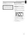
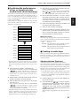
Before using this unit, carefully read the sections entitled: “IMPORTANT SAFETY
INSTRUCTIONS” (p. 2), “USING THE UNIT SAFELY” (p. 3), and “IMPORTANT
NOTES” (p. 11). These sections provide important information concerning the proper
operation of the unit. Additionally, in order to feel assured that you have gained a
good grasp of every feature provided by your new unit, this manual should be read
in its entirety. The manual should be saved and kept on hand as a convenient
reference.
R
L
A
2
3
4
1
B
2
3
INPUT SENS
2
PEAK
10
4
PEAK
10
IN
OUT THRU
SCSI
POWER
MIDI
IN
DIGITAL(5,6)
MIXER MODE
3
PEAK
10
OUT
FOOT
SWITCH
4
INPUT B
INPUT A
1
PHONES
AUX SEND
MASTER OUT
1
PHONES
TIME VALUE
PEAK
10
SELECT
TRACK
INPUT
CONDITION MARKER#
TIME
INPUT MIX
dB
TRACK MIX
4
50 dBm
4
50 dBm
4
50 dBm
4
0
50 dBm
10
0
4
PAN
PAN
PAN
PAN
PAN
PAN
PAN
PAN
C
C
C
C
C
C
C
C
AUX SEND
12
24
48
0
INPUT TRACK
L
Input BUSS
V.Track
EQ
BUSS Send
AUX Send
Channel Link
EFFECT - 1
-2
SOURCE
R
L
R
L
R
L
R
L
R
L
R
L
R
L
R
AUX MASTER
6 dB
EDIT CONDITION
CH EDIT
CH EDIT
CH EDIT
CH EDIT
CH EDIT
CH EDIT
CH EDIT
CH EDIT
Input BUSS
V.Track
EQ Low
EQ Mid
EQ Hi
Aux Send
EFFECT - 1
EFFECT - 2
SOLO
SONG
LOCATOR
SEL
SEL
SEL
SEL
SEL
SEL
SEL
SEL
Master Out
AUX SEND
EFFECT - 1
-2
EDIT
Marker
Locate
Loop
A.Punch I O
STATUS
STATUS
STATUS
STATUS
STATUS
STATUS
STATUS
STATUS
Song Select
- New
- Name
- Copy
- Erase
- Optimize
DAT Backup
- Recover
1
2
3
4
5
6
7
8
AUX
BUSS
AUX
BUSS
AUX
BUSS
REC
TRACK
PLAY
EFFECT
Track Copy
EFFECT - 1
- Move
-2
- Xchg
- Insert
- Cut
- Erase
Time Comp Exp.
SYSTEM
System
MIDI
DISK
Sync
Scene
Drive Select
- Initialize
PARAMETER
DISPLAY
Pre Level
Post Level
Play List
Fader Pan
SHIFT
Amp Profile
CURSOR
NO
YES
CANCEL
ENTER
UNDO
MIDI /
DISK
PLAY
MUTE
BUSS
a
b
c
d
MARKER
AUX
(dB)
(dB)
6
6
4
4
0
0
4
4
8
8
12
18
LOCATOR
MASTER
PREVIOUS
NEXT
1
2
TAP
LOOP
AUTO PUNCH
3
4
5
NUMERICS
VARI PITCH
PREVIEW
1/
LOC
5
6
1/
2/
LOC
6
LOC
7
5
2/
3/
8
3/
6
7
4/
LOC
8
9
7
4/
CLEAR
SCENE
SCRUB
TO
FROM
0
8
CLEAR
12
18
24
24
36
36
STORE
SONG TOP
SONG END
SHUT EJECT
RESTART
ZERO
REW
FF
STOP
PLAY
REC
Copyright © 1996 ROLAND CORPORATION
All rights reserved. No part of this publication may be reproduced in
any form without the written permission of ROLAND CORPORATION.
CAUTION
RISK OF ELECTRIC SHOCK
DO NOT OPEN
ATTENTION: RISQUE DE CHOC ELECTRIQUE NE PAS QUVRIR
CAUTION: TO REDUCE THE RISK OF ELECTRIC SHOCK,
DO NOT REMOVE COVER (OR BACK).
NO USER-SERVICEABLE PARTS INSIDE.
REFER SERVICING TO QUALIFIED SERVICE PERSONNEL.
The lightning flash with arrowhead symbol, within an
equilateral triangle, is intended to alert the user to the
presence of uninsulated “dangerous voltage” within the
product’s enclosure that may be of sufficient magnitude to
constitute a risk of electric shock to persons.
The exclamation point within an equilateral triangle is
intended to alert the user to the presence of important
operating and maintenance (servicing) instructions in the
literature accompanying the product.
INSTRUCTIONS PERTAINING TO A RISK OF FIRE, ELECTRIC SHOCK, OR INJURY TO PERSONS.
IMPORTANT SAFETY INSTRUCTIONS
SAVE THESE INSTRUCTIONS
WARNING - When using electric products, basic precautions should always be followed, including the following:
1. Read all the instructions before using the product.
2. Do not use this product near water — for example, near a
bathtub, washbowl, kitchen sink, in a wet basement, or near
a swimming pool, or the like.
3. This product should be used only with a cart or stand that is
recommended by the manufacturer.
4. This product, either alone or in combination with an amplifier
and headphones or speakers, may be capable of producing
sound levels that could cause permanent hearing loss. Do
not operate for a long period of time at a high volume level
or at a level that is uncomfortable. If you experience any
hearing loss or ringing in the ears, you should consult an
audiologist.
5. The product should be located so that its location or position
does not interfere with its proper ventilation.
6. The product should be located away from heat sources such
as radiators, heat registers, or other products that produce
heat.
7. The product should be connected to a power supply only of
the type described in the operating instructions or as marked
on the product.
8. The power-supply cord of the product should be unplugged
from the outlet when left unused for a long period of time.
9. Care should be taken so that objects do not fall and liquids
are not spilled into the enclosure through openings.
10.The product should be serviced by qualified service
personnel when:
A. The power-supply cord or the plug has been damaged; or
B. Objects have fallen, or liquid has been spilled onto the
product; or
C. The product has been exposed to rain; or
D. The product does not appear to operate normally or
exhibits a marked change in performance; or
E. The product has been dropped, or the enclosure
damaged.
11.Do not attempt to service the product beyond that described
in the user-maintenance instructions. All other servicing
should be referred to qualified service personnel.
For the USA
GROUNDING INSTRUCTIONS
This product must be grounded. If it should malfunction or breakdown, grounding provides a path of least resistance for
electric current to reduce the risk of electric shock.
This product is equipped with a cord having an equipment-grounding conductor and a grounding plug. The plug must be
plugged into an appropriate outlet that is properly installed and grounded in accordance with all local codes and ordinances.
DANGER: Improper connection of the equipment-grounding conductor can result in a risk of electric shock. Check with a
qualified electrician or serviceman if you are in doubt as to whether the product is properly grounded.
Do not modify the plug provided with the product — if it will not fit the outlet, have a proper outlet installed by a qualified
electrician.
For the U.K.
THIS APPARATUS MUST BE EARTHED
WARNING:
IMPORTANT: THE WIRES IN THIS MAINS LEAD ARE COLOURED IN ACCORDANCE WITH THE FOLLOWING CODE.
GREEN-AND-YELLOW: EARTH, BLUE: NEUTRAL, BROWN: LIVE
As the colours of the wires in the mains lead of this apparatus may not correspond with the coloured markings identifying
the terminals in your plug, proceed as follows:
The wire which is coloured GREEN-AND-YELLOW must be connected to the terminal in the plug which is marked by the
letter E or by the safety earth symbol or coloured GREEN or GREEN-AND-YELLOW.
The wire which is coloured BLUE must be connected to the terminal which is marked with the letter N or coloured BLACK.
The wire which is coloured BROWN must be connected to the terminal which is marked with the letter L or coloured RED.
The product which is equipped with a THREE WIRE GROUNDING TYPE LINE PLUG must be grounded.
Used for instructions intended to alert
the user to the risk of death or severe
injury should the unit be used
improperly.
Used for instructions intended to alert
the user to the risk of injury or material
damage should the unit be used
improperly.
* Material damage refers
other adverse effects
respect to the home
furnishings, as well
animals or pets.
to damage or
caused with
and all its
to domestic
● Before using this unit, make sure to read the
instructions below, and the OwnerÕs Manual.
.........................................................................................................
● Do not open or perform any internal modifications
on the unit. (The only exception would be where
Quick Start manual provides specific instructions
which should be followed in order to put in place
user-installable options; see p. 3.)
.........................................................................................................
● Make sure you always have the unit placed so it is
level and sure to remain stable. Never place it on
stands that could wobble, or on inclined surfaces.
.........................................................................................................
● Avoid damaging the power cord. Do not bend it
excessively, step on it, place heavy objects on it, etc.
A damaged cord can easily become a shock or fire
hazard. Never use a power cord after it has been
damaged.
.........................................................................................................
● In households with small children, an adult should
provide supervision until the child is capable of
following all the rules essential for the safe operation of the unit.
.........................................................................................................
● Protect the unit from strong impact.
(Do not drop it!)
.........................................................................................................
● Do not force the unitÕs power-supply cord to share
an outlet with an unreasonable number of other
devices. Be especially careful when using extension cordsÑthe total power used by all devices
you have connected to the extension cordÕs outlet
must never exceed the power rating
(watts/amperes) for the extension cord. Excessive
loads can cause the insulation on the cord to heat
up and eventually melt through.
.........................................................................................................
The
symbol alerts the user to important instructions
or warnings.The specific meaning of the symbol is
determined by the design contained within the
triangle. In the case of the symbol at left, it is used for
general cautions, warnings, or alerts to danger.
The
symbol alerts the user to items that must never
be carried out (are forbidden). The specific thing that
must not be done is indicated by the design contained
within the circle. In the case of the symbol at left, it
means that the unit must never be disassembled.
The ● symbol alerts the user to things that must be
carried out. The specific thing that must be done is
indicated by the design contained within the circle. In
the case of the symbol at left, it means that the powercord plug must be unplugged from the outlet.
● Always turn the unit off and unplug the power
cord before attempting installation of the Hard
disk drive unit (HDP88 series) or Effect expansion
board VS8F-1.
● Always grasp only the plug on the power-supply
cord when plugging into, or unplugging from an
outlet.
.........................................................................................................
● Try to prevent cords and cables from becoming
entangled. Also, all cords and cables should be
placed so they are out of the reach of children.
.........................................................................................................
● Never climb on top of, nor place heavy objects on
the unit.
.........................................................................................................
● Never handle the power cord or its plugs with wet
hands when plugging into, or unplugging from, an
outlet or this unit.
.........................................................................................................
● Before moving the unit, disconnect the power plug
from the outlet, and pull out all cords from external devices.
.........................................................................................................
● Before cleaning the unit, turn off the power and
unplug the power cord from the outlet.
.........................................................................................................
● Whenever you suspect the possibility of lightning
in your area, pull the plug on the power cord out
of the outlet.
.........................................................................................................
● When installing the Hard disk drive unit (HDP88
series) or Effect expansion board VS8F-1, remove
only the specified screws.
● Before using the unit in a foreign country, consult with
your dealer, or qualified Roland service personnel.
3
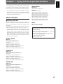
Introduction
Thank you for purchasing the Roland VS-880 V-XPANDED Digital Studio Workstation or the VS880-S1 System Expansion Kit.
The VS-880 V-XPANDED is a revolution in home studio equipment that makes a cutting-edge studio environment available to the musician. Disk recorder, digital mixer, and multi effects are
brought together in a unified system that allows the entire process from recording to mixdown,
effects and output to PA equipment to take place entirely in the digital domain.
The VS-880-S1 is an expansion kit that enhances the system software of the VS-880 that you have
been using to full V-XPANDED functionality. In addition to the superb digital studio functionality
that you have already been enjoying, you will now be able to experience even more powerful functions and even easier operation.
The documentation for VS-880 V-XPANDED consists of two manuals: ÒQuick StartÓ and ÒOwnerÕs
ManualÓ (this document). If you are using the VS-880 for the first time, please read ÒQuick StartÓ
first.
About the package contents
■ If you purchased the VS-880 V-XPANDED
The VS-880 V-XPANDED package includes the following items. Make sure that you have all the
items.
• VS-880
• Power cable
• Quick Start
• Owner’s Manual (this manual)
• VS8F-1 Preset Patch List
• Leaflet “Notes when using a Zip drive”
• V-XPANDED sticker
■ If you purchased the VS-880-S1
The VS-880-S1 package includes the following items. Make sure that you have all the items.
• VS-880-S1 (Zip disk)
• Expanding the functionality of the VS-880
• Owner’s Manual (this manual)
• VS8F-1 Preset Patch List
• V-XPANDED sticker
How this manual is organized
This manual is organized as follows.
■ Chapter 1 Trying out the expanded functions
This chapter provides some simple examples which explain the operation of the expanded VS-880.
If you have purchased the VS-880-S1, read this first to learn which functions are added by the VXPANDED upgrade.
If you purchased the VS-880 V-XPANDED, read the separate ÒQuick StartÓ first.
■ Chapter 2 Before you start (VS-880 terminology)
This chapter explains basic concepts that you will need to understand in order to use the VS-880.
It also explains various terms that you should know.
■ Chapter 3 Basic operation (as a replacement for a
tape MTR)
This chapter explains the actual steps in the procedure of creating a master tape.
4
Introduction
■ Chapter 4 Editing a recorded performance (track
editing)
This chapter explains the procedure for Òediting sound,Ó something which was not possible on
conventional tape MTR units.
■ Chapter 5 Use with MIDI devices
This chapter explains the procedures for using the VS-880 in conjunction with MIDI devices. Read
this chapter when you wish to use the VS-880 in synchronization with other MIDI devices.
■ Chapter 6 Use with a Zip drive
This chapter explains the procedures for using the VS-880 with a Zip drive. Read this chapter when
you wish to use a Zip drive to record a performance. This chapter also explains how to use the VS880 with a hard disk or magneto-optical disk.
■ Chapter 7 Use with a DAT recorder
This chapter explains the procedures for using the VS-880 in conjunction with a DAT recorder.
Read this chapter when you wish to save your performance on a DAT recorder.
■ Chapter 8 Using the internal effects
This chapter explains the operating procedures when a VS8F-1 effect expansion board is installed.
Read the VS8S-1 ownerÕs manual in conjunction with this chapter.
■ Chapter 9 Other convenient functions
This chapter explains operation of functions which were not discussed in earlier chapters, such as
sounding the metronome during recording, or when a foot switch is connected.
■ Chapter 10 Overall settings and status checking
This chapter explains how to make the settings which affect the overall operation of the VS-880.
■ Chapter 11 Taking advantage of the VS-880 (ideas
and examples)
This chapter combines some of the functions discussed in earlier chapters, and gives some actual
examples of how you can take advantage of the VS-880.
■ Appendices
This chapter contains material which will help you make the best use of the VS-880, such as
ÒTroubleshootingÓ and ÒError message list.Ó
5
Contents
Main features .................................................................................................................. 10
Important notes .............................................................................................................. 11
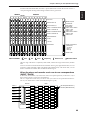
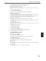
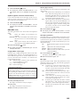
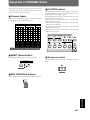
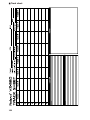
Front and rear panels ..................................................................................................... 13
Mixer section .......................................................................................................................................... 13
Recorder section ..................................................................................................................................... 14
Display section ....................................................................................................................................... 15
Rear panel ............................................................................................................................................... 16
Chapter 1 Trying out the expanded functions
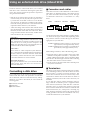
Mixer-related .................................................................................................................. 17
Using auto mix ....................................................................................................................................... 17
Using the 3-band equalizer in INPUT MIX/TRACK MIX .............................................................. 20
Mixing in a stereo source (Stereo In) ................................................................................................... 21
Adjusting the level of each track (Track Level) ................................................................................. 21
Causing top panel fader and pan knob operations to take effect immediately ............................ 21
Recorder related functions ............................................................................................. 22
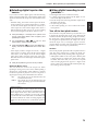
When the Recording mode is set to Mastering .................................................................................. 22
When a digital signal with emphasis is input ................................................................................... 22
Creating a master tape which disables digital copying ................................................................... 22
Effect related .................................................................................................................. 23
Newly added preset patches ................................................................................................................ 23
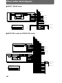
Newly added algorithms ...................................................................................................................... 23
Adjusting the send level and balance for all effects .......................................................................... 33
Inserting an effect ................................................................................................................................... 34
Display related ................................................................................................................ 37
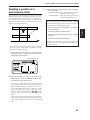
Holding the level meter peaks ............................................................................................................. 37
Checking the remaining disk capacity ................................................................................................ 37
Disk drive related ............................................................................................................ 38
Checking the reliability of a disk ............................................................................................................... 38
Checking that a disk is not damaged .................................................................................................. 38
Synchronization related .................................................................................................. 40
Assign mark points according to the tempo ...................................................................................... 40
When using the sync track ................................................................................................................... 40
Using the tempo map ............................................................................................................................ 42
Adding an offset to the sync track/tempo map ................................................................................ 42
MIDI related .................................................................................................................... 43
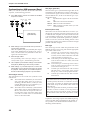
Using program change messages to select scenes ............................................................................ 43
Using program change messages to select effects ............................................................................. 43
Using control change messages to control effects ............................................................................ 43
Other .............................................................................................................................. 44
Using the numeric keys ([NUMERICS]) ............................................................................................. 44
Holding the function of [SHIFT] (Shift Lock) .................................................................................... 44
Easy time adjustment ............................................................................................................................ 45
Chapter 2 Before you start (VS-880 terminology)
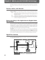
Sources, tracks, and channels ....................................................................................... 46
Doing everything in the digital domain (Digital Studio Workstation) ............................... 46
Signal flow (busses) ....................................................................................................... 46
Where a performance is recorded (Song) ...................................................................... 47
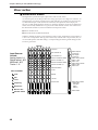
Mixer section .................................................................................................................. 48
About mixer modes ............................................................................................................................... 48
Switching the mixer mode .................................................................................................................... 51
Recording the current condition of the mixer (Scene) ...................................................................... 51
Recorder section ............................................................................................................ 53
Differences with a tape-type MTR ...................................................................................................... 53
Number of tracks that can be recorded/played simultaneously ................................................... 53
Virtual tracks provided for each track (V-tracks) ............................................................................. 53
Effects section ................................................................................................................ 54
About the effect expansion board (VS8F-1) ....................................................................................... 54
VS-880 operation ........................................................................................................... 54
How operations are organized (Conditions) ..................................................................................... 54
Switching conditions ............................................................................................................................. 54
6
Contents
Selecting the operation menu .............................................................................................................. 55
Selecting parameters ............................................................................................................................. 55
Modifying the value of settings ........................................................................................................... 55
Executing an operation ........................................................................................................................ 55
Switching the track status (Track Status) ........................................................................................... 55
Changing the current time .................................................................................................................... 56
Storing a time location, method 1 (Locate Point) ............................................................57
Storing a time location .......................................................................................................................... 57
Moving to a stored time location ......................................................................................................... 58
Modifying a stored time location ........................................................................................................ 58
Deleting a stored time location ............................................................................................................ 58
Storing a time location, method 2 (Mark Points) ............................................................ 59
Marking a time location ........................................................................................................................ 59
Moving to a marked time location ...................................................................................................... 59
Modifying a marked time location ...................................................................................................... 60
Clearing a mark ...................................................................................................................................... 60
Chapter 3 Basic operation (as a replacement for a tape MTR)
Before you begin ............................................................................................................ 61
When you turn the power on .............................................................................................................. 61
Listening to the demo song ............................................................................................ 61
Listening to the variations of the demo song .................................................................................... 61
Making a new recording ................................................................................................. 62
Specifying the recording mode (Song New) ...................................................................................... 62
Naming the song (Song Name) ............................................................................................................ 62
General procedure for multitrack recording .................................................................... 63
Connect the instruments ....................................................................................................................... 63
Record a performance onto a track ..................................................................................................... 63
Switching V-tracks ................................................................................................................................. 63
Recording additional tracks while listening to the performance (Overdubbing) ........................ 64
Re-recording only your mistakes (Punch-in/out) ............................................................................ 64
Specify beforehand the location for re-recording (Auto punch-in) ................................................ 65
Repeatedly recording over the same area (Loop recording) ........................................................... 66
Combining the performances of two or more tracks into another track (Track bouncing) ........ 67
Creating a master tape .......................................................................................................................... 67
Digital recording ............................................................................................................. 72
Concerning copyright ........................................................................................................................... 72
About SCMS ........................................................................................................................................... 72
Connecting digital devices ................................................................................................................... 72
Matching the sampling frequency ....................................................................................................... 72
Selecting digital input as the source .................................................................................................... 73
When digital recording is not possible ... ........................................................................................... 73
Before you finish operations ........................................................................................... 74
Saving the performance to disk (Song Store) ..................................................................................... 74
Preventing accidental erasure of your performance (Song Protect) ............................................... 74
Selecting a song (Song Select) .............................................................................................................. 75
Turning the power off (Shut Down) ................................................................................................... 75
Re-starting the VS-880 ................................................................................................... 75
Chapter 4 Editing a recorded performance (track editing)
What is editing? .............................................................................................................. 76
Finding a desired location (Preview) ...............................................................................76
Using [TO] and [FROM] ....................................................................................................................... 76
Scrub playback ([SCRUB]) .................................................................................................................... 76
Basic procedure ............................................................................................................. 77
Re-using part of the performance (Copy) ....................................................................... 78
Modifying the organization of the performance (Move) .................................................. 79
Erasing part of a performance (Erase) ........................................................................... 81
Exchanging performance data between tracks (Exchange) ........................................... 81
Inserting blank space into a performance (Insert) .......................................................... 82
Deleting a portion of a performance (Cut) ...................................................................... 83
Modifying the playback time of the performance (Time compression/expansion) .......... 84
7
Contents
Chapter 5 Use with MIDI devices
About MIDI ..................................................................................................................... 85
What is MIDI .......................................................................................................................................... 85
MIDI connectors ..................................................................................................................................... 85
MIDI channels ........................................................................................................................................ 85
MIDI messages ....................................................................................................................................... 85
MIDI implementation chart .................................................................................................................. 85
Using MIDI to switch the track status ............................................................................. 86
Synchronizing with a MIDI sequencer ............................................................................ 86
Using MTC .............................................................................................................................................. 86
Using the tempo map ............................................................................................................................ 89
Using the sync track .............................................................................................................................. 91
When you experience problems with synchronization ................................................... 92
Chapter 6 Use with a Zip drive
Connecting a Zip drive ................................................................................................... 93
Initializing the disk (Drive Initialize) .................................................................................93
Select the Zip drive as the recording destination (Drive Select) ..................................... 93
Saving performance data on a Zip disk (Song Copy) ..................................................... 94
Saving on a single disk (Playable) ....................................................................................................... 94
When the data cannot be saved on a single disk (Archive) ............................................................. 95
If you have problems saving the data ............................................................................. 96
Chapter 7 Use with a DAT recorder (DAT backup)
Saving performance data to a DAT recorder (Backup) .................................................. 97
Loading performance data from a DAT recorder (Recover) ............................................98
Checking the names of the performance data that was saved (Name) ......................................... 99
Checking the storage status of performance data that was saved (Verify) ................................... 99
Chapter 8 Using the internal effects
Examples of how the effects can be used .................................................................... 100
Applying reverb to a recorded performance (Loop) ...................................................................... 100
Applying reverb as you record (Loop) ............................................................................................. 102
Applying a vocoder while you record (Insert) ................................................................................ 104
Applying reverb while bouncing tracks (Loop) .............................................................................. 106
If the effect does not sound as you expect ................................................................... 108
Chapter 9 Other convenient functions
Sounding the metronome ............................................................................................. 109
Using an external MIDI sound source to play the metronome ..................................................... 109
Using a foot switch to playback/stop ............................................................................ 110
Stopping automatically (Marker stop) ........................................................................... 110
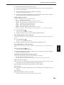
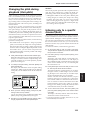
Changing the pitch during playback (Vari-pitch) ........................................................... 111
Listening only to a specific channel (Solo) ................................................................... 111
Simultaneously adjusting a stereo source (Channel Link) ........................................... 112
Undoing a recording or editing operation ..................................................................... 112
Recording/editing operations which can be undone (Undo) ....................................................... 112
Canceling the last-performed Undo (Redo) ..................................................................................... 113
Canceling only the last-performed operation .................................................................................. 113
When the disk has little remaining space ..................................................................... 113
Deleting only unneeded performance data (Song Optimize) ....................................................... 113
Deleting one song of performance data (Song Erase) .................................................................... 113
Chapter 10 Overall settings and status checking
If the display area is difficult to read (Contrast) ............................................................ 114
Switching the contents of the display (Bar Display) ..................................................... 114
Displaying measures/beats .......................................................................................... 115
Checking the size of a recorded performance .............................................................. 115
Restoring the mixer settings to the initial state ............................................................. 116
If there is no internal hard disk ..................................................................................... 116
8
Contents
Chapter 11 Taking advantage of the VS-880 (ideas and examples)
Recording multiple sources to one track ...................................................................... 117
Collecting just the sections that you like ....................................................................... 118
Copying an 8-track MTR performance to the VS-880 .................................................. 119
Controlling the mixer from a MIDI sequencer ............................................................... 120
Operating the VS-880 from another device (MMC) ...................................................... 122
Synchronizing the operation of two VS-880 units .......................................................................... 122
Operating the VS-880 from an MMC-compatible device .............................................. 125
If you have problems with synchronization .................................................................................... 126
Using external effect units ............................................................................................ 127
Applying an effect during playback ................................................................................................. 127
Applying an effect while you re-record ........................................................................................... 127
Appendices
Using an external disk drive (About SCSI) ................................................................... 130
Troubleshooting ............................................................................................................ 132
Error messages ............................................................................................................ 134
Special key operations ................................................................................................. 136
Parameter list ............................................................................................................... 138
MIDI implementation chart ........................................................................................... 143
Mixer section block diagram ......................................................................................... 144
Glossary ....................................................................................................................... 145
Specifications ............................................................................................................... 146
About the V-XPANDED sticker ..................................................................................... 147
Index ............................................................................................................................. 149
* Iomega is a registered trademark of Iomega Corporation.
* Zip is a trademark of Iomega Corporation.
* All product names mentioned in this document are trademarks or registered trademarks of their
respective owners.
9
Main features
■ Digital audio workstation
■ A full complement of connectors
The digital disk recorder section provides 8 tracks, and
allows four tracks to be recorded simultaneously. Each
track has eight virtual tracks (V-tracks), allowing a total
maximum of 64 tracks to be recorded. This means that you
can use convenient techniques such as recording numerous
takes of guitar solos, vocals, or chorus.
Four analog audio inputs are provided, and you have the
choice of using either 1/4Ó phone jacks or RCA phono type
jacks. The input sensitivity of each jack can be adjusted from
line level (+4 dBm) to mic level (-50 dBm). For output, RCA
phono type master out jacks (stereo) and AUX send jacks
(two output) are provided.
Editing operations such as copy, move and erase which
were impossible for a tape MTR can be easily accomplished.
For example, a four-measure drum pattern that was recorded can be repeated several times as a break-beat. Or, you
might place the same chorus at the beginning and end of a
song.
A SCSI connector is standard, allowing you to connect
external disk drives such as hard disks or removable disks.
The VS-880 uses non-destructive editing, a method unique
to disk recorders. Previously performed recording or editing operations can be undone up to 999 steps backward (the
Undo/Redo function).
MIDI connectors (IN, OUT/THRU) allow MIDI messages to
be transmitted and received. The VS-880 can be used with a
MIDI sequencer for compu-mix, or synchronized with a
MIDI sequencer.
Up to eight sets of all mixer settings (scenes) can be stored
for each song. When you wish to adjust the balance during
mixdown, or to compare effect settings, you can easily recall
the previous settings.
In addition to the tracks which record the audio signals, the
VS-880 has a sync track which can record MIDI Clock data.
By using this sync track, the VS-880 can be synchronized
even with a MIDI sequencer which does not implement
MTC (MIDI Time Code) or MMC (MIDI Machine Control).
For each song, up to 32 time locations (locate points) can be
stored. If you register times such as the end of the introduction or the beginning of a break, you will be able to jump
immediately to desired points in a song without having to
fast-forward or rewind.
Up to 1000 time locations in each song can be marked (mark
points). It is useful to place marks at the beginning of each
measure, or at locations that you wish to listen to.
A sync track can be created from mark points that were
assigned along with the tempo. By transmitting MIDI clock
messages according to the sync track, you can easily synchronize the VS-880 with a MIDI sequencer.
Time-based movements of channel faders and pan etc. can
be recorded (auto mix). With no additional equipment, the
VS-880 can perform mixing operations such as fade in and
fade out.
■ Easy-to-operate controls
The VS-880 can be operated as easily as conventional analog
multi-track recorders. You will be able to enjoy the advantages of digital recording from the day that you purchase it.
The large LCD screen provides visual confirmation of many
settings at once. In particular, the bar display provides a
graphical indication of the level meter, pan and fader settings, and the track record status.
10
Coaxial type digital I/O connectors are provided, allowing
recording/playback of digital audio with another digital
audio device (CD player, DAT recorder, MD recorder, etc.)
■ A full array of options
If an HDP-88 series hard disk (2.5 inch) is installed internally, the VS-880 will be a self-contained, compact, and
portable recording system. In contrast to when external disk
drives are used, there will be no possibility of problems
resulting from faulty connections. We recommend that you
install an internal hard disk when using the VS-880.
If a VS8F-1 effect expansion board is installed, a wide variety of effects will be available for use on the VS-880.
In addition to the items listed under ÒIMPORTANT SAFETY INSTRUCTIONSÓ and ÒUSING THE UNIT SAFELYÓ on
pages 2 and 3, please read and observe the following:
Power Supply
● Do not use this unit on the same power circuit with any
device that will generate line noise (such as an electric
motor or variable lighting system).
● Before connecting this unit to other devices, turn off the
power to all units. This will help prevent malfunctions
and/or damage to speakers or other devices.
Placement
● Using the unit near power amplifiers (or other equipment containing large power transformers) may induce
hum. To alleviate the problem, change the orientation of
this unit; or move it farther away from the source of
interference.
● This device may interfere with radio and television
reception. Do not use this device in the vicinity of such
receivers.
● Do not expose the unit to direct sunlight, place it near
devices that radiate heat, leave it inside an enclosed vehicle, or otherwise subject it to temperature extremes.
Excessive heat can deform or discolor the unit.
Maintenance
● For everyday cleaning wipe the unit with a soft, dry
cloth or one that has been slightly dampened with water.
To remove stubborn dirt, use a cloth impregnated with a
mild, non-abrasive detergent. Afterwards, be sure to
wipe the unit thoroughly with a soft, dry cloth.
● Never use benzene, thinners, alcohol or solvents of any
kind, to avoid the possibility of discoloration and/or
deformation.
Chapter 1
Important notes
Disk drive handling
Disk drives are precision devices. When handling a VS-880
that has an internal hard disk installed, or when handling
an external disk drive, observe the following precautions.
● For details on hard disk handling, refer also to the
instructions that accompanied your hard disk.
● Before performing the following actions, be sure to perform the shut-down operation. If you fail to perform the
shut-down operation, not only the data recorded on the
hard disk, but also the hard disk itself may be damaged.
Turning off the power of the disk drive
Turning off the power of the VS-880
Removing a disk from a removable disk drive
● While the MIDI/DISK indicator of the VS-880 or the disk
drive busy indicator is lit, data is being transferred to or
from the disk drive. If you are using a removable disk
drive, make sure that this indicator is dark before removing the disk.
● Place the unit in a stable and level location that is not
affected by vibration from external sources. If the unit is
tilted severely, this may have harmful effects on the
operation of the disk drive.
● While using the VS-880, be careful not to subject the unit
to vibration or shock, and avoid moving the unit while
the power is turned on. When transporting the unit, pack
it in its original shipping carton.
● Avoid using the unit immediately after it has been
moved to a location with a level of humidity that is
greatly different than its former location. Rapid changes
in the environment can cause condensation to form
inside the drive, which will adversely affect the operation of the drive and/or damage removable disks. When
the unit has been moved, allow it to become accustomed
to the new environment (allow a few hours) before operating it.
Repairs and Data
● Please be aware that all data contained in the unitÕs
memory may be lost when the unit is sent for repairs.
Important data should always be backed up on a DAT
recorder or an external disk drive (e.g., hard disk or MO
disk). During repairs, due care is taken to avoid the loss
of data. However, in certain cases (such as when circuitry
related to memory itself is out of order), we regret that it
may not be possible to restore the data, and Roland
assumes no liability concerning such loss of data.
11
Important notes
Concerning copyright
Additional Precautions
The law prohibits the unauthorized recording, public performance, broadcast, sale, or distribution etc. of a work (CD
recording, video recording, broadcast, etc.) whose copyright
is owned by a third party.
The VS-880 does not implement SCMS. This design decision
was made with the intent that SCMS should not restrict the
creation of original compositions which do not violate copyright law. Roland will take no responsibility for any
infringement of copyright that you may commit in using
the VS-880.
● Please be aware that the contents of memory can be irretrievably lost as a result of a malfunction, or the improper operation of the unit. To protect yourself against the
risk of loosing important data, we recommend that you
periodically save a backup copy of important data you
have stored in the unitÕs memory on a DAT recorder or
an external disk drive (e.g., hard disk or MO disk).
< About SCMS >
ÒSCMSÓ stands for ÒSerial Copy Management System.Ó
This is a function that protects the rights of copyright
holders by prohibiting recording via a digital connection
for more than two generations. When digital connections
are made between digital recorders that implement this
function, SCMS data will be recorded along with the
audio data. Digital audio data which contains this SCMS
data cannot again be recorded via a digital connection.
Disclaimer of liability
Roland will take no responsibility for any Òdirect damages,Ó
Òconsequential damages,Ó or Òany other damagesÓ which
may result from your use of the VS-880. These damages
may include but are not limited to the following events
which can occur when using the VS-880.
Any loss of profit that may occur to you
Permanent loss of your music or data
Inability to continue using the VS-880 itself or a connected device
● Unfortunately, it may be impossible to restore the contents of data that was stored on a DAT recorder or an
external disk drive (e.g., hard disk or MO disk) once it
has been lost. Roland Corporation assumes no liability
concerning such loss of data.
● Use a reasonable amount of care when using the unitÕs
buttons, sliders, or other controls; and when using its
jacks and connectors. Rough handling can lead to malfunctions.
● Never strike or apply strong pressure to the display.
● When connecting / disconnecting all cables, grasp the
connector itselfÑnever pull on the cable. This way you
will avoid causing shorts, or damage to the cableÕs internal elements.
● A small amount of heat will radiate from the unit during
normal operation.
● To avoid disturbing your neighbors, try to keep the
unitÕs volume at reasonable levels. You may prefer to use
headphones, so you do not need to be concerned about
those around you (especially when it is late at night).
● When you need to transport the unit, package it in the
box (including padding) that it came in, if possible.
Otherwise, you will need to use equivalent packaging
materials.
12
Mixer section
INPUT SENS
1
2
PEAK
10
MIXER MODE
3
PEAK
10
4
PEAK
10
PHONES
PEAK
10
SELECT
TRACK
INPUT
INPUT MIX
TRACK MIX
4
50 dBm
4
50 dBm
4
50 dBm
4
0
50 dBm
PAN
PAN
PAN
PAN
PAN
PAN
PAN
PAN
C
C
C
C
C
C
C
C
10
AUX SEND
0
L
Input BUSS
V.Track
EQ
BUSS Send
AUX Send
Channel Link
EFFECT - 1
-2
SOURCE
R
L
R
L
R
L
R
L
R
L
R
L
R
L
R
6 dB
CH EDIT
CH EDIT
CH EDIT
CH EDIT
CH EDIT
CH EDIT
CH EDIT
CH EDIT
Input BUSS
V.Track
EQ Low
EQ Mid
EQ Hi
Aux Send
EFFECT - 1
EFFECT - 2
SOLO
Master Out
AUX SEND
EFFECT - 1
-2
SEL
SEL
SEL
SEL
SEL
SEL
SEL
SEL
STATUS
STATUS
STATUS
STATUS
STATUS
STATUS
STATUS
STATUS
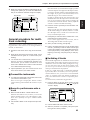
EDIT
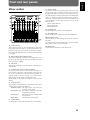
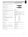
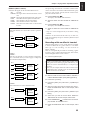
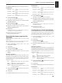
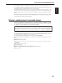
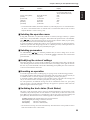
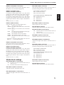
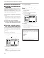
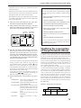
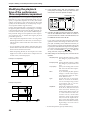
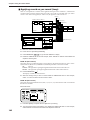
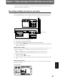
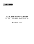
7. SELECT button
This button switches the operating mode of the mixer. The
current mixer mode is shown by the indicators located at
the right of the button. Each time you press the button, you
will alternate between INPUT MIX mode and TRACK MIX
mode. To change from INPUT➝ TRACK mode to INPUT
MIX mode / TRACK MIX mode, hold down [SHIFT] and
press the button. Use the same operation to move in the
other direction.
INPUT➝TRACK mode
INPUT MIX mode
TRACK MIX mode
REC
PLAY
MUTE
1
BUSS
(dB)
6
4
0
4
8
a
2
3
AUX
BUSS
b
4
5
AUX
BUSS
c
6
7
AUX
BUSS
8
d
MASTER
AUX
(dB)
8. PHONES knob
This knob adjusts the volume of the headphones.
6
4
0
4
9. AUX SEND knob
This knob adjusts the output level of the AUX SEND jacks.
8
12
12
18
18
24
24
36
36
1. PEAK indicators
These indicators allow you to avoid distortion of the sound
being input at the input jacks (1Ð4). The peak indicators will
light red when the signal reaches -6 dB before clipping
level. Adjust the input sensitivity so that the peak indicators
do not light.
10. EDIT/SOLO button
Press this button to make settings for the master section of
the mixer.
To use the Solo function to monitor only a specific channel,
hold [SHIFT] while you press the button.
11. Master fader
Use this fader to adjust the overall output level.
2. INPUT SENS (input sensitivity) knobs
These knobs adjust the sensitivity of the input jacks (1Ð4).
Rotate a knob fully right for mic level (-50 dBm), and fully
left for line level (+4 dBm).
3. PAN knobs
These knobs adjust the pan (location in the stereo output) of
each channel.
4. CH EDIT / SEL (channel edit/select) buttons
Use these buttons when you wish to make settings for a
mixer channel. The names of the parameter groups that can
be set for each channel are printed below CH EDIT. To
directly specify a particular group, you can hold down
[SHIFT] and press the button for that group name.
When editing a song, use these buttons to select tracks for
editing.
5. STATUS buttons
These buttons switch the status of each channel. The current
status is shown by the button indicator.
SOURCE (orange): The input source assigned to the
channel is being output.
REC (blinking red): Recording is selected for the track
assigned to the channel.
PLAY (green):
The track assigned to the channel
will playback.
MUTE (dark):
The channel is muted (silent).
6. Channel faders
Use these faders to adjust the volume level of each channel.
13
Chapter 1
Front and rear panels
Front and reat panels
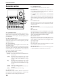
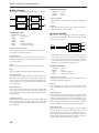
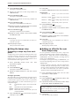
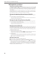
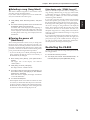
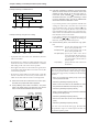
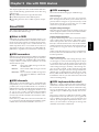
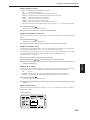
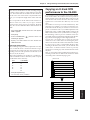
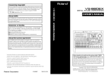
6. PARAMETER buttons
Use these buttons to switch the parameter display.
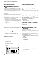
Recorder section
7. SHIFT button
This button is used in conjunction with other buttons to
access additional functions of that button. For details refer
to ÒSpecial key operationsÓ (p.136).
TIME VALUE
EDIT CONDITION
SONG
LOCATOR
Song Select
- New
- Name
- Copy
- Erase
- Optimize
DAT Backup
- Recover
Marker
Locate
Loop
A.Punch I O
TRACK
PLAY
EFFECT
Track Copy
EFFECT - 1
- Move
-2
- Xchg
- Insert
- Cut
- Erase
Time Comp Exp.
SYSTEM
System
MIDI
DISK
Sync
Scene
Drive Select
- Initialize
PARAMETER
DISPLAY
Pre Level
Post Level
Play List
Fader Pan
SHIFT
Amp Profile
LOCATOR
CURSOR
NO
YES
CANCEL
ENTER
UNDO
MIDI /
DISK
8. CURSOR buttons, NO/YES buttons, CANCEL/ENTER
buttons
When a YES/NO response is required during an operation,
use these button to reply. When two or more parameters are
shown in the display, use these buttons to select parameters.
MARKER
PREVIOUS
NEXT
1
2
TAP
LOOP
AUTO PUNCH
3
4
5
NUMERICS
VARI PITCH
PREVIEW
1/
LOC
5
6
1/
2/
LOC
6
LOC
7
5
2/
3/
8
3/
6
7
4/
LOC
8
9
7
4/
CLEAR
SCENE
SCRUB
TO
FROM
0
8
CLEAR
STORE
SONG TOP
SONG END
SHUT EJECT
RESTART
ZERO
REW
FF
STOP
PLAY
REC
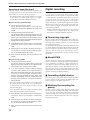
1. PLAY/DISPLAY button
Press this button to return from making a setting (edit condition) back to normal status (play condition). To switch
display items in the bar display, hold down [SHIFT] and
press this button.
2. EDIT CONDITION buttons
The functions and parameters of the VS-880 are organized
within these buttons. To use a desired operation, press the
appropriate button.
3. LOCATOR buttons
Press these buttons when using the Locator function or the
Tap Marker function.
When the NUMERICS indicator is lit, these buttons function
as numeric keys to directly input numbers. When the
SCENE indicator is lit, these buttons are used to store and
recall scenes (snapshots of mixer settings).
4. Transport control buttons
These buttons are used to operate the recorder.
[ZERO]: Return the current time to Ò00h00m00s00Ó
(zero return).
[REW]:
While the button is held down, the current
time will be moved backward. This corresponds to the rewind button on a tape
recorder.
[FF]:
While the button is held down, the current
time will be moved forward. This corresponds to the fast-forward button on a tape
recorder.
[STOP]: Stop song recording/playback.
[PLAY]: Start song recording/playback from the current time.
[REC]:
Press this button to record a song.
5. TIME/VALUE dial
Normally (i.e., in Play condition), this dial is used to move
the current time. When making settings (i.e., in Edit condition), this dial is used to modify parameter values.
14
9. NUMERICS button
When this button is pressed to make the indicator light, the
ten LOCATOR buttons will act as numeric keys to enter
numerical values.
10. VARI PITCH button
Press this button when you wish to change the playback
pitch.
11. UNDO button
Press this button to cancel a recording that you have made.
Also, after performing a song edit operation, you can press
this button to return to the condition before editing. When
undo is executed, the button indicator will light.
12. MIDI/DISK indicator
This indicator will light green when MIDI messages are
being received, and red when data is being written or read
on the disk drive. If both of these are occurring, the indicator will light orange.
13. SCENE button
Press this button when you wish to memorize or recall
scenes (snapshots of the mixer settings).
14. PREVIEW button
Press this button to use the Preview function that plays back
a specific length before and after the current location.
Front and reat panels
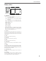
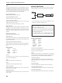
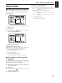
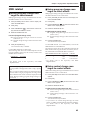
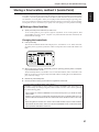
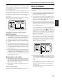
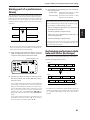
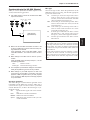
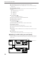
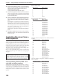
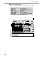
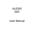
Display section
CONDITION MARKER#
TIME
dB
0
4
12
24
48
INPUT TRACK
AUX MASTER
1. CONDITION
This indicates the current condition.
PLY: Play (normal. When turn the Song Protect on,
ÒPlyÓ will be indicated.)
CHn: Channel edit (n=1Ð8, aÐd) (in INPUT➝TRACK
MIX mode)
INn: Channel edit (n=1Ð6, aÐc) (in INPUT MIX mode)
TRn: Channel edit (n=1Ð8, aÐd) (in TRACK MIX mode)
MST: Master block edit
SNG: Song edit
LOC: Locator edit
TRK: Track edit
EFF: Effect edit
SYS: System edit
* The channel edit display will depend on the currently
selected mixer mode. Also, channels for which Channel
Link is OFF will be displayed as 1Ð8, and channels for
which it is ON will be displayed as aÐd.
2. MARKER
This shows the mark point number for the current time. If a
mark point has not been assigned to the current time, the
closest mark point number located before the current time
will be shown.
3. TIME
This shows the current time of the song.
4. MEASURE
This shows the current measure of the song.
5. BEAT
This shows the current beat of the song.
6. SYNC MODE
This indicates the current sync mode (method of synchronization).
7. SCENE
This shows the currently used scene number (mixer setting).
An asterisk Ò✱Ó shown at the beginning of the scene number indicates that the current mixer settings have been modified since the scene was recalled.
8. REMAINING TIME
This shows the remaining length of time available for
recording.
9. Bar display
In Play condition, the item selected by [DISPLAY (PLAY)]
are shown graphically. While you are making a setting, data
for the setting being made is displayed graphically.
15
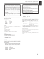
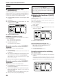
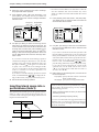
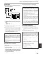
Front and reat panels
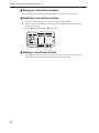
Rear panel
SCSI
MIDI
OUT THRU
IN
DIGITAL (5,6) FOOT
PHONES
SWITCH
IN
INPUT B
4
3
B
A
INPUT A
2
1
R
L
4
3
2
1
AC IN
OUT
AUX SEND
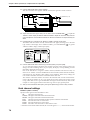
1. POWER switch
This switch turns the VS-880 power on/off.
2. AC IN (AC inlet)
Connect the included power cable here.
3. SCSI connector
This is a DB-25 type SCSI connector for connecting disk drives such as hard disks or removable disks. If you wish to
connect a disk drive, refer to ÒUse with a Zip driveÓ (p.93).
4. MIDI connectors (IN, OUT/THRU)
External MIDI devices (MIDI controllers, MIDI sequencers,
etc.) can be connected here.
IN:
This connector receives MIDI messages.
Connect it to the MIDI OUT connector of
the external MIDI device.
OUT/THRU: This connector can be used either as a
MIDI OUT or as a MIDI THRU connector.
With the factory settings, it will function
as a MIDI OUT connector.
5. DIGITAL (5,6) connectors (IN, OUT)
These are coaxial-type digital I/O connectors (comforms to
S/P DIF).
IN:
This inputs a digital audio signal (stereo).
OUT: This outputs a digital audio signal (stereo). The
sound is the same as that of the MASTER OUT
jacks.
* To record a digital audio signal, it is not sufficient to simply connect a digital audio device to the DIGITAL IN connector. When inputting a digital audio signal, refer to
ÒDigital recordingÓ (p.72).
* The DIGITAL connector is not able to input or output
analog audio signals.
6. FOOT SWITCH jack
An optional foot switch can be connected here to control
recorder operations, mark point settings, and punch in/out
operations etc. by foot switch. With the factory settings, a
foot switch will start/stop the recorder. To change this
function, refer to ÒUsing a footswitch to playback/stopÓ
(p.110).
16
MASTER OUT
7. PHONES jack
An optional set of headphones can be connected here. The
PHONES jack outputs the same sound as the MASTER
OUT jack.
8. INPUT B jacks (1–4)
9. INPUT A jacks (1–4)
These are input jacks for analog audio signals. INPUT A are
1/4Ó phone jacks, and INPUT B are RCA phono jacks. You
may use either type of jack. If cables are connected to both
types, the INPUT A jacks will take priority. Use the INPUT
SENS knob to adjust the input sensitivity of each input.
10. AUX SEND jacks (A,B)
11. MASTER OUT jacks (L,R)
These are output jacks for analog audio signals (RCA phono
type).
With the factory settings, all signals will be output from the
MASTER OUT jacks, and there will be no output from the
AUX SEND jacks. The output will be determined by the settings of the mixerÕs master section and the settings of each
channel.
The AUX SEND jacks can also be used as send jacks for connecting external effect units (p.127).
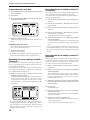
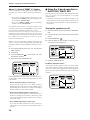
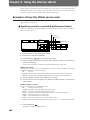
This chapter provides some simple examples which explain
the operation of the expanded VS-880. Read the explanations in sequence to learn about the newly added functions.
* If a song created on the VS-880 V-XPANDED is loaded by
VS-880 Ver.1, data for the functions added in V-XPANDED (Auto Mix etc.) may be lost. To prevent this from happening, turn Song Protect on (p.74).
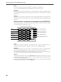
Mixer-related
■ Using auto mix
Time based movements such as channel faders and pan can
now be recorded to mark points (auto mix). When you
move to a mark point, the recorded mixer settings will be
reproduced.
Auto mix can be recorded separately in each mixer mode.
The mixer settings which can be recorded are as follows.
* The items printed in bold type can be adjusted directly
from the faders or pan knobs on the top panel. By operating these while a song is playing back, you can record
time-based mixer movements such as fade-in or panning.
When Channel Link is on, the channel faders and pan
knobs of even-numbered channels will respectively adjust
AUX level and AUX balance.
Chapter 1
Chapter 1 Trying out the expanded functions
Master Block
MasterLevel
Master Bal (Master Balance)
AUX Level
AUX Bal (AUX Balance)
EFFECT1 SND Lev (Effect 1 Send Level)
EFFECT1 SND Bal (Effect 1 Send Balance)
EFFECT1 RTN Lev (Effect 1 Return Level)
EFFECT1 RTN Bal (Effect 1 Return Balance)
EFFECT2 SND Lev (Effect 2 Send Level)
EFFECT2 SND Bal (Effect 2 Send Balance)
EFFECT2 RTN Lev (Effect 2 Return Level)
EFFECT2 RTN Bal(Effect 2 Return Balance)
Effect
EFFECT-1 (Effect 1 Number)
EFFECT-2 (Effect 2 Number)
< How auto mix differs from scenes >
In that auto mix Òrecords mixer settings,Ó its functionality
is similar to scenes.
It differs from scenes in the following ways. Use the two
functions as appropriate for your needs.
1000 can be recorded (the number of mark points).
Valid even during song playback.
Cannot switch the mixer mode.
Cannot switch V-tracks.
INPUT➝TRACK
MIX Level
MIX Pan/MIX Bal (Mix Balance)
AUX Level
AUX Pan/AUX Bal (AUX Balance)
EFFECT1 Send (Effect 1 Send Level)
EFFECT1 Pan/EFFECT1 Bal (Effect 1 Balance)
EFFECT2 Send (Effect 2 Send Level)
EFFECT2 Pan/EFFECT2 Bal (Effect 2 Balance)
INPUT MIX
BUSS Level
BUSS Pan/BUSS Bal (BUSS Balance)
AUX Level
AUX Pan/AUX Bal (AUX Balance)
EFFECT1 Send (Effect 1 Send Level)
EFFECT1 Pan/EFFECT1 Bal (Effect 1 Balance)
EFFECT2 Send (Effect 2 Send Level)
EFFECT2 Pan/EFFECT2 Bal (Effect 2 Balance)
TRACK MIX
BUSS Level
BUSS Pan/BUSS Bal (BUSS Balance)
AUX Level
AUX Pan/AUX Bal (AUX Balance)
EFFECT1 Send (Effect 1 Send Level)
EFFECT1 Pan/EFFECT1 Bal (Effect 1 Balance)
EFFECT2 Send (Effect 2 Send Level)
EFFECT2 Pan/EFFECT2 Bal (Effect 2 Balance)
17
Chapter 1 Trying out the expanded functions
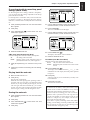
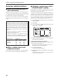
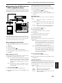
Preparations for auto mix
1. Press [SYSTEM] several times until “SYS Scene/Auto
Mix?” is displayed.
2. Press [YES].
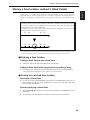
3. Press PARAMETER [
A.Mix Mode=” appears.
] several times until “SYS
CONDITION MARKER#
This method creates an auto mix that smoothly connects the
mixer settings recorded in two adjacent mark points.
For example, this is convenient when you wish to fade-in or
fade-out at a specified time.
1. Move to the time location at which you wish to begin the
auto mix.
TIME
dB
0
4
12
24
48
INPUT TRACK
AUX MASTER
4. Rotate the TIME/VALUE dial.
When the setting is on, the [SELECT] indicator will
blink.
A.Mix Mode (Auto mix mode)
Off: Auto mix mode will not be used (same as in Ver.1).
On: Auto mix mode will be used.
5. Press [PLAY(DISPLAY)].
Return to Play condition.
* By holding down [SCENE] and pressing [SELECT], you
can turn Auto Mix Mode on/off in a single operation.
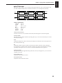
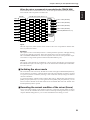
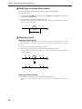
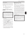
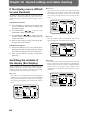
Recording the mixer settings, method 1
(Snapshot)
Mixer settings can be recorded in a Mark point. When you
move to that Mark point, the mixer settings that were
recorded will be reproduced.
For example, this is convenient when you want the intro
and ending to have different volume levels for the guitar
part or different effect send levels etc.
1. Make sure that Auto Mix is on, press holding down
[SCENE] and pressing [TAP].
A mark point will be added at the current time location.
At the same time, the settings of the mixer will be
recorded at the mark point. A mark point in which
mixer settings are recorded will be indicated by an Ò✱Ó
following it.
CONDITION MARKER#
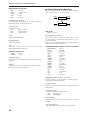
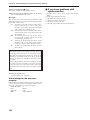
Recording the mixer settings, method 2
(Gradation)
2. Perform the procedure for “Recording the mixer settings, method 1”.
3. Move to the time location at which you wish to end the
auto mix.
4. Perform the procedure for “Recording the mixer settings, method 1” once again.
Two mark points have now been assigned.
5. Make sure that auto mix is on, holding down [SCENE]
and pressing [PREV].
A mark point will be automatically added between the
two mark points, and the mixer settings will be interpolated.
* If you wish to interpolate with the previous mark point,
press [SCENE]+[PREV]. If you wish to interpolate with
the next mark point, holding down [SCENE] and pressing
[NEXT].
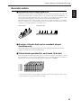
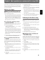
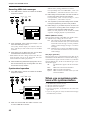
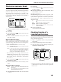
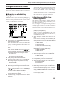
Recording the mixer settings, method 3
(Realtime)
With this method, only those the mixer settings which can
be adjusted from the top panel will be recorded to mark
points in realtime. For example, this is convenient when
you wish to fade-in or fade-out individual tracks.
1. Move to the time location at which you wish to record
the auto mix.
2. Make sure that auto mix is on, holding down [SCENE]
and pressing [REC].
The CONDITION column display will alternate
between the current condition name and Òmix,Ó indicating that preparations have been made for realtime
recording of the auto mix.
3. Specify the channels for with auto mix will be recorded.
Move the faders and pan knobs of the top panel to the
desired locations.
4. Press [PLAY].
Playback will begin.
TIME
dB
0
4
12
24
5. Operate the channel faders, pan knobs, and master
fader of the top panel.
Auto mix data will be recorded only for those channels
which were modified.
48
INPUT TRACK
AUX MASTER
* If a mark point already exists within 0.1 seconds before
the time location at which you are attempting to place a
new mark point (i.e., the current time), the auto mix data
will be recorded at the earlier mark point. A mark point
will not be newly assigned.
18
6. When the mix is finished, press [STOP].
Mark points will be automatically created in the area
which was played back.
If you wish to redo the auto mix, repeat steps 1Ð5.
If you do not wish to record top panel
settings (Mask Fader)
CONDITION MARKER#
In ÒRecording the mixer settings, method 1 (Snapshot)Ó,
you can specify that the settings adjustable from the top
panel will not be recorded.
For example, this is convenient when you have made fadein settings according to ÒRecording the mixer settings,
method 2Ó, and then wish to modify the effect send levels,
etc.
TIME
dB
0
4
12
24
48
INPUT TRACK
AUX MASTER
1. Press [SYSTEM] several times until “SYS Scene/Auto
Mix?” appears.
5. Use the TIME/VALUE dial to specify the first mark point
of the area in which you wish to erase the auto mix.
2. Press [YES].
6. Press CURSOR[ ].
The cursor will move toward the right.
3. Press PARAMETER [
A.Mix Snap=” appears.
] several times until “SYS
CONDITION MARKER#
7. Use the TIME/VALUE dial to specify the last mark point
of the area in which you wish to erase the auto mix.
TIME
CONDITION MARKER#
TIME
dB
0
dB
0
4
INPUT TRACK
12
4
24
12
48
24
48
AUX MASTER
INPUT TRACK
4. Rotate the TIME/VALUE dial.
A.Mix Snap (Auto Mix Snapshot Mode)
Select the settings that will be recorded by the snapshot.
All:
All settings will be recorded.
MaskF: Settings which can be adjusted by the top
panel (channel faders etc.) will be ignored.
5. Press [PLAY(DISPLAY)]. You will return to Play condition.
6. Perform the procedure of “Recording the mixer settings,
method 1”.
Playing back the auto mix
1. Make sure that auto mix is on.
2. Press [PLAY].
The auto mix will playback.
While the auto mix is playing back, operating a fader or
pan knob will cause auto mix to be defeated for that
channel. If you stop and then playback again, auto mix
will once again take effect. Alternatively, you can temporarily turn Auto Mix off during playback and then
turn it on again, causing Auto Mix to again be valid.
Erasing the auto mix
1. Press [SYSTEM] several times until “SYS Scene/Auto
Mix?” appears.
2. Press [YES].
3. Press PARAMETER [
A.Mix Erase?” appears.
4. Press [YES].
] several times until “SYS
AUX MASTER
8. Press PARAMETER [
].
The display will indicate ÒSYS EraseMode=Ó.
9. Rotate the TIME/VALUE dial.
EraseMode (Auto Mix Erase Mode)
Select the auto mix data which will be erased.
Event:
Only auto mix events will be erased.
Marker: Both mark points and auto mix events will be
erased.
10. Press PARAMETER [
].
The display will indicate ÒSYS Erase___<=>___?Ó. The
underlined area will display the mark points specified
in steps 5Ð7.
11. Press [YES].
A message will ask you to confirm that you really wish
to erase the data.
12. Press [YES] once again.
The auto mix will be erased.
< What is an event? >
The smallest unit of memory used by the VS-880 to store
recorded results on disk is the event. A newly created
song provides approximately 12,000 events per song.
For each track, one recording pass uses two events.
Operations such as punch-in/out or track copy also use
up events. The number of events that are used up will
fluctuate in a complex way. For example, auto mix uses
up five events for each mark point.
Even if there is capacity remaining on the disk, further
recording or track editing will not be possible if all of the
events are used up. In such cases, an error message such
as ÒEvent Mem FullÓ will appear (p.134).
19
Chapter 1
Chapter 1 Trying out the expanded functions
Chapter 1 Trying out the expanded functions
About “!!! Lack of EVENT !!” display
Ò!!! Lack of EVENT !!Ó will be appeared in the display in the
following cases, and you cannot continue the current operation.
¥ If you push [SCENE]+[REC] buttons to record
AutoMix data in realtime, when the remaining number of EVENT is less than 1000.
¥ If you try to UNDO or REDO when the remaining
number of Event is less than 200.
The smallest unit of memory used by the VS-880 to store
recorded results on disk are the events. A newly created
song provides approximately 12,000 events per song.
For each track, one recording pass uses two events.
Operations such as punch-in/out or track copy also use up
events. The number of events that are used up will fluctuate
in a complex way. For example, auto mix uses up five
events for each mark point.
When you do a lot of recording, editing (Track Copy, Track
Move) or record AutoMix of long period, please check the
remaining number of Events frequently. Procedure is as follows.
■ Using the 3-band equalizer in
INPUT MIX/TRACK MIX
From the total of fourteen INPUT MIX/TRACK MIX channels, you can now use a 3-band equalizer on any eight
selected channels.
* If equalizer is turned on for more than 8 channels, it will
not be possible to use the 3-band equalizer. Please turn off
the equalizer switch for channels on which equalization is
not required.
Turning the equalizer on/off
1. Make sure that the mixer mode is INPUT MIX/TRACK
MIX.
2. Hold down [SHIFT], and press channel 3 [EQ Low(CH
EDIT)].
3. Press PARAMETER [
].
4. Press [CH EDIT] for the channels or tracks for which
you wish to turn the equalizer off.
CONDITION MARKER#
TIME
1. Press [SYSTEM] several times until “SYS System
PRM?” appears.
0
2. Press [YES].
12
dB
4
3. Press PARAMETER [
RemainDsp=” appears.
24
] several times until “SYS
48
INPUT TRACK
AUX MASTER
4. Select “Event” with TIME/VALUE dial.
5. Rotate the TIME/VALUE dial.
CONDITION MARKER#
TIME
EQ Switch (equalizer switch)
dB
0
4
12
24
48
INPUT TRACK
AUX MASTER
Remaining number of Events can be saved with the following procedures. Please try the most appropriate one with
your situation.
• Execute Song Store (Owner's manual p.74)
Please Execute Song Store if in UNDO condition
([UNDO] indicator is lit.). Events served for REDO will be
released. But please note that you cannot cancel (REDO)
the last UNDO if you once execute STORE.
• Execute Song Optimize (Owner's manual p.113)
Please execute Song Optimize if you have done a lot of
Punch In recording. Events served for unnecessary audio
data will be released. But please note that you can only do
single level UNDO.
• Erace AutoMix data (Owner's manual p.19)
If you have recorded AutoMix data, erase unnecessary
data. Events served for unnecessary AutoMix data will be
released.
20
If you wish to use the equalizer, set this ÒOn.Ó If not, set this
ÒOff.Ó When equalizer settings are being made, the equalization curve will be shown graphically in the bar display. If
this is ÒOffÓ the equalizer-related parameters will not be
available.
CONDITION MARKER#
TIME
dB
0
4
12
24
48
INPUT TRACK
AUX MASTER
Using the 3-band equalizer
1. Make sure that the mixer mode is INPUT MIX/TRACK
MIX.
If it is INPUT➝TRACK, holding down [SHIFT] and
pressing [SELECT].
2. Press [EDIT(SOLO)] several times until “MST EQ Sel=”
appears.
■ Adjusting the level of each track
(Track Level)
It is now possible to adjust the volume level of each track
independently from the channel faders.
For example, this is convenient when you wish to raise the
track level for playback of a track which was recorded at a
low volume level.
3. Rotate the TIME/VALUE dial.
1. Press [CH EDIT] for the track whose volume you wish
to adjust.
EQ Sel (Equalizer Select)
2. Press PARAMETER [
“TrackLevel=” appears.
Select the type of equalizer that you wish to use.
2BandEQ:
14 channels of 2-band equalizers (same as
Ver.1).
3BandEQ:
8 channels of 3-band equalizers.
■ Mixing in a stereo source
(Stereo In)
Even when playing back all 8 tracks in INPUT➝TRACK,
you can now mix in a stereo source for output to master
out.
For example, this is convenient when two VS-880 units are
being operated in synchronization.
1. Press [EDIT(SOLO)] several times until “MST
StereoIn=” appears.
2. Select the input source for the stereo source. Rotate
the TIME/VALUE dial.
StereoIn (Stereo In)
Off:
Input12:
Input34:
Digital:
Stereo In will not be used.
Inputs 1 and 2 will be input in stereo.
Inputs 3 and 4 will be input in stereo.
The digital input will be input in stereo.
] several times until
3. Rotate the TIME/VALUE dial.
TrackLevel (Track Level)
The volume level of each track can be adjusted over a range
of -12Ð12dB.
■ Causing top panel fader and
pan knob operations to take
effect immediately
When the volume or pan has been adjusted in Channel Edit
condition, switching between INPUT MIX and TRACK MIX
can cause the fader or pan knob locations to no longer
match the actual volume level or pan. In such cases, an Ò✱Ó
symbol will be appended to the displayed values of the settings. Also, when the fader or pan locations are shown in
the bar display, the current channel fader locations will
blink.
1. Press [SYSTEM] several time until “SYS System PRM
?” appears.
2. Press [YES].
3. Press PARAMETER [
].
The display will indicate ÒMST StIn Level=Ó.
3. Press PARAMETER [
FaderMatch” appears.
4. Adjust the volume level of the stereo input. Rotate the
TIME/VALUE dial.
4. Rotate the TIME/VALUE dial.
5. Press PARAMETER [
].
The display will indicate ÒMST StIn Bal=Ó.
6. Adjust the left/right balance of the stereo input. Rotate
the TIME/VALUE dial.
] several times until “SYS
FaderMatch (Fader Match)
Select how the faders will act when the fader or pan knob
locations do not match the actual volume level or panning.
Null:
Changes will not occur until the channel
fader or pan knob is moved to the actual
value (same as Ver.1).
Jump:
The actual value will change at the instant
that the fader or pan knob is moved.
5. Press [PLAY(DISPLAY)].
You will return to Play condition.
21
Chapter 1
Chapter 1 Trying out the expanded functions
Chapter 1 Trying out the expanded functions
Recorder related functions
■ Creating a master tape which
disables digital copying
■ When the Recording mode is
set to Mastering
When digitally mixing down from the VS-880 to a DAT
recorder etc., you can now prohibit digital copies from
being made from the mixdown tape.
For example, a single-generation of digital recording from a
CD player to a DAT recorder is permitted. It will not be
possible to make a digital copy from the digitally-recorded
DAT to another digital device (p.72). This function causes a
tape which is digitally recorded from the VS-880 to behave
in the same way as a tape digitally recorded from a CD.
When the Recording mode (p.62) is set to Mastering (MAS),
it is now possible to playback up to six tracks simultaneously. At this time, the VS-880 will function as a 6-track
recorder (tracks 1-6). Tracks 7Ð8 cannot be used.
Previously, only four tracks could be played back simultaneously when the Recording mode was set to Mastering
(MAS).
< When using a Zip drive >
A Zip drive is not able to read or write data with sufficient speed. For this reason, when it is being used as the
current drive (i.e., the drive for recording or playback), it
will not be possible to playback six tracks simultaneously.
Refer to the following table, and limit the number of
simultaneously played back tracks accordingly. For
details refer to the enclosed leaflet ÒNotes when using a
Zip drive.Ó
1. Press [SYSTEM] several times until “SYS System
PRM?” appears.
2. Press [YES].
3. Press PARAMETER [
D.CpyProtect=” appears.
CONDITION MARKER#
] several times until “SYS
TIME
dB
0
* Numbers are guidelines for numbers of tracks that can
be played back simultaneously.
Numbers in parentheses ( ) are guidelines for numbers
of tracks in song in which operations such as punch-in
recording or track copy are performed repeatedly.
Recording mode
Mastering
Multitrack 1
Multitrack 2
Live
Sample rate
48.0kHz 44.1kHz
3(2)
4(2)
7(6)
7(5)
7(6)
8(7)
8(8)
8(8)
32.0kHz
5(4)
8(6)
8(8)
8(8)
■ When a digital signal with
emphasis is input
When a digital signal with emphasis is input from the digital in connector, it will be automatically de-emphasized.
22
4
12
24
48
INPUT TRACK
AUX MASTER
4. Rotate the TIME/VALUE dial. If you wish to prohibit digital copying, turn the setting on.
D.CpyProtect (Digital Protect Switch)
Specify whether or not digital copying of a digitally-mixed
down tape will be permitted or not.
Off: Digital copying will be permitted (same as Ver.1).
On: Digital copying will be prohibited.
5. Press [PLAY(DISPLAY)].
You will return to Play condition.
6. Digitally mixdown from the VS-880 to a DAT recorder
etc. (p.73).
It will not be possible to digitally copy this master tape
to another DAT recorder etc.
Effect related
When a VS8F-1 effect expansion board is installed, a single
VS-880 now allows you to use two stereo effects.
Please read the VS8F-1 ownerÕs manual together with this
explanation.
■ Newly added preset patches
One hundred preset patches have been added to the effect
patches. Refer to the included ÒPreset Patch List.Ó
Due to the increased number of preset patches, the patch
numbers have changed as follows.
Ver.1
Preset 001Ð100
(newly added)
User 001Ð100
V-XPANDED
Preset A00ÐA99
Preset B00ÐB99
User U00ÐU99
Reverb 2 (p.23)
Space Chorus (p.24)
Lo-Fi Processor (p.25)
4-Band Parametric Equalizer (p.26)
10-Band Graphic Equalizer (p.27)
Hum Canceler (p.28)
Vocal Canceller (p.28)
Vocoder 2 (p.29)
Voice Transformer (p.30)
Mic Simulator (p.32)
HPF (High pass filter)
Adjust the frequency at which the high pass filter will begin
to take effect. With a setting of Thru, the high pass filter will
not function.
LPF (Low pass filter)
Adjust the frequency at which the low pass filter will begin
to take effect. With a setting of Thru, the low pass filter will
not function.
This is a reverb that provides a gating function and a ducking function. It can be used in either EFFECT-1 or EFFECT2. You can use two reverbs with different settings, or use it
in combination with a previous reverb.
Direct Level
Output L
Equalizer
EFLevel (Effect level)
Adjust the volume of the reverb.
DiLevel (Direct level)
Adjust the volume of the direct sound.
Gate
Turn the gate function on/off. When this is off, the following items will not be displayed.
Reverb
Equalizer
Output R
REV (Reverb)
Reverb
Type
Time
PreDLY
Density
HPF
LPF
EFLevel
DiLevel
Gate
Type (Reverb Type)
Select the type of reverb.
Room1: Normal room reverb.
Room2: Room reverb with a softer tone than Room1.
Hall1:
Normal hall reverb.
Hall2:
Hall reverb with a softer tone than Hall1.
Plate:
Plate reverb.
Density
Adjust the density of the reverb.
● Reverb 2
Direct Level
Reverb
Turn reverb on/off. When turned off, the following items
will not be displayed.
PreDLY (Pre delay)
Adjust the time until the reverb is output.
The following effect algorithms have been added.
Input R
Gate, Ducking
0Ð100
1Ð100
1Ð100
1Ð100
Time
Adjust the length (time) of the reverberation.
■ Newly added algorithms
Input L
Mode
Thresh
Attack
Release
HoldTime
On, Off
Room1, Room2, Hall1, Hall2, Plate
0.1Ð10.0 sec
0Ð200 msec
0Ð100
Thru, 20Ð2000 Hz
1.0Ð20.0 kHz, Thru
0Ð100
0Ð100
Off, On
Mode (Gate mode)
Select the way in which the gate function will operate.
Gate:
The gate will begin to open when the direct
signal level exceeds the threshold level, and
will begin to close when it falls below the
threshold level.
Ducking: The function will be the opposite of the Gate
setting. The gate will begin to close when the
direct signal level exceeds the threshold level,
and will begin to open when it falls below the
threshold level.
Thresh (Threshold)
Adjust the basic level at which opening and closing of the
gate will be controlled.
23
Chapter 1
Chapter 1 Trying out the expanded functions
Chapter 1 Trying out the expanded functions
Attack
Adjust the time from when the direct sound level exceeds
the threshold level until when the gate is completely open.
Release
Adjust the time from when the hold time has elapsed until
the sound is completely muted.
HoldTime
Adjust the time from when the input falls below the threshold level until when the release begins.
EQ (Equalizer)
EQ
LowType
Low.G
Low.F
Low.Q
Mid.G
Mid.F
Mid.Q
HiType
Hi.G
Hi.F
Hi.Q
OutLevel
Off, On
Shlv, Peak
-12Ð12 dB
20Ð2000 Hz
0.3Ð10
-12Ð12 dB
200Ð8000 Hz
0.3Ð10
Shlv, Peak
-12Ð12 dB
1.4Ð20.0 kHz
0.3Ð10
0Ð100
EQ (Equalizer)
Turn the equalizer on/off. If this is turned off, the following
items will not be displayed.
Mid.Q (Middle Q)
Specify the width of the band around the center frequency
specified for the middle range equalizer in which the gain
adjustment will occur. As this setting is raised, the width of
the band affected will become narrower.
HiType (High type)
Select the type of high range equalizer.
Shlv:
Shelving type
Peak:
Peaking type
Hi.G (High gain)
Specify the gain (amount of boost/cut) for the high range
equalizer.
Hi.F (High frequency)
Specify the center frequency of the high range equalizer.
Hi.Q (High Q)
Specify the width of the band around the center frequency
specified for the high range equalizer in which the gain
adjustment will occur. As this setting is raised, the width of
the band affected will become narrower.
OutLevel (Output level)
Adjust the volume level after the sound has passed through
the equalizer.
● Space Chorus
This is a chorus which simulates the Roland SDD-320.
LowType
Select the type of the low range equalizer.
Shlv:
Shelving type
Peak:
Peaking type
Low.G (Low gain)
Specify the gain (amount of boost/cut) for the low range
equalizer.
Low.F (Low frequency)
Specify the center frequency of the low range equalizer.
Low.Q (Low Q)
Specify the width of the band around the center frequency
specified for the low range equalizer in which the gain
adjustment will occur. As this setting is raised, the width of
the band affected will become narrower.
Mid.G (Middle gain)
Specify the gain (amount of boost/cut) for the mid-range
equalizer.
Mid.F (Middle frequency)
Specify the center frequency of the mid-range equalizer.
24
Output L
Input L
Space Chorus
Input R
Output R
SCH (Space Chorus)
SpaceCho
InMod
Mode
MixBal
Off, On
Mono, Stereo
1, 2, 3, 4, 1+4, 2+4, 3+4
0Ð100
SpaceCho (Space Chorus)
Turn space chorus on/off. If this is turned off, the following
items will not be displayed.
InMod (Input mode)
Specify whether the input signal is stereo or mono.
Mode (Space mode)
Select the way in the chorus will change.
MixBal (Mix balance)
Adjust the balance between the chorus volume and the
direct sound volume.
● Lo-Fi Processor
This allows you to create a Òlo-fiÓ sound by lowering the sample rate and/or decreasing the number of bits. Realtime modify filters connected in series allow you to reshape the sound freely.
Input L
Input R
Output L
Lo-Fi
Processor
Realtime
Modify Filter
Noise
Suppressor
Lo-Fi
Processor
Realtime
Modify Filter
Noise
Suppressor
Output R
LFP (Lo-fi processor)
LoFiPros
PreFilt
Rate
Bit
PostFilt
EFLevel
DiLevel
Off, On
Off, On
Off, 1/2Ð1/32
Off, 15Ð1 bit
Off, On
0Ð100
0Ð100
LoFiPros (Lo-fi processor)
Turn the Lo-fi Processor on/off. If this is turned off, the following items will not be displayed.
PreFilt (Pre filter)
This filter decreases digital distortion. By turning this off, you can create an extremely lo-fi sound
that includes aliasing.
Rate
Modify the sample rate. If this is turned off, the sample rate will be the same as the sample rate of
the currently selected song.
Bit
Modify the number of data bits. If this is turned off, the number of data bits will be unchanged.
If an extremely low number of bits is selected, loud noise may appear even when there is no sound,
depending on the input source. In such cases, raise the threshold of the noise suppressor.
PostFilt (Post filter)
This filter decreases the digital distortion produced by lo-fi. By turning this off, you can create an
extremely lo-fi sound.
EFLevel (Effect level)
Adjust the volume of the lo-fi sound.
DiLevel (Direct level)
Adjust the volume of the direct sound.
25
Chapter 1
Chapter 1 Trying out the expanded functions
Chapter 1 Trying out the expanded functions
RMF (Realtime modify filter)
RMF
Type
CutOff
Reso
Gain
Off, On
LPF, BPF, HPF
0Ð100
0Ð100
0Ð24 dB
● 4-Band Parametric Equalizer
This is a 4-band parametric equalizer. It can be used either
as two monaural units or as one stereo unit.
Input A
Output A
Equalizer
RMF (Realtime modify filter)
Turn the realtime modify filter on/off. If this is turned off,
the following items will not be displayed.
Link
Equalizer
Input B
Type (Filter type)
Select the filter type.
LPF:
Low pass filter
BPF:
Band pass filter
HPF:
High pass filter
CutOff
Adjust the cutoff frequency.
Reso (Resonance)
Adjust the resonance.
Gain
Adjust the volume level of the sound that has passed
through the realtime modify filter.
NS (Noise suppressor)
Thresh
Release
0Ð100
0Ð100
Thresh (Threshold)
Adjust the level at which the noise suppressor will begin to
take effect.
Release
Adjust the time from when the noise suppressor begins to
take effect until the volume reaches 0.
Output B
LNK (Link)
EQLink
Off, On
EQLink (Equalizer link switch)
This is a link switch for channels A and B. If this is turned
off, the channels will function independently as two
monaural channels.
If this is turned on, both channels will be controlled simultaneously by the settings of channel A.
EQA/EQB (Parametric equalizer channel A / channel B)
EQAch(EQBch)
InputG
LowType
LowG
LowF
LowQ
LoMidG
LoMidF
LoMidQ
HiMidG
HiMidF
HiMidQ
HiType
HiG
HiF
HiQ
Level
Off, On
-60Ð12dB
Shlv, Peak
-12Ð12 dB
20Ð2000 Hz
0.3Ð10
-12Ð12 dB
200Ð8000 Hz
0.3Ð10
-12Ð12 dB
200Ð8000 Hz
0.3Ð10
Shlv, Peak
-12Ð12 dB
1.4Ð20.0 kHz
0.3Ð10
-60Ð12 dB
EQA/EQB (Equalizer channel A / channel B)
Turn the equalizer on/off. When this is turned off, the following items will not be displayed.
InputG (Input gain)
Adjust the overall volume level of the sound before it enters
the equalizer.
LowType (Low type)
Select the type of the low range equalizer.
Shlv:
Shelving type
Peak:
Peaking type
LowG (Low gain)
Specify the gain (amount of boost/cut) for the low range
equalizer.
LowF (Low frequency)
Specify the center frequency of the low range equalizer.
26
LowQ (Low Q)
Specify the width of the band centered on the low range
equalizer center frequency in which the gain adjustment
will occur. As this setting is raised, the width of the band
affected will become narrower.
● 10-Band Graphic Equalizer
This simulates a 10-band graphic equalizer. It can be used
either as two monaural units or as one stereo unit.
Input A
Output A
Equalizer
LoMidG (Low middle gain)
Specify the gain (amount of boost/cut) for the low middle
range equalizer.
Link
Equalizer
LoMidF (Low middle frequency)
Specify the center frequency of the low middle range equalizer.
LoMidQ (Low middle Q)
Specify the width of the band centered on the low middle
range equalizer center frequency in which the gain adjustment will occur. As this setting is raised, the width of the
band affected will become narrower.
HiMidG (High middle gain)
Specify the gain (amount of boost/cut) for the high middle
range equalizer.
HiMidF (High middle frequency)
Specify the center frequency of the high middle range
equalizer.
HiMidQ (High middle Q)
Specify the width of the band centered on the high middle
range equalizer center frequency in which the gain adjustment will occur. As this setting is raised, the width of the
band affected will become narrower.
HiType (High type)
Select the type of high range equalizer.
Shlv:
Shelving type
Peak:
Peaking type
Input B
Output B
LNK (Link)
EQLink
Off, On
EQLink (Equalizer link)
This is the link switch for channels A and B. When this is
turned off, the channels will function independently as two
monaural equalizers.
When this is turned on, both channels will be controlled
simultaneously by the settings of channel A.
EQA/EQB (Graphic equalizer channel A / channel B)
EQAch(EQBch)
InputG
31.2Hz
62.5Hz
125Hz
250Hz
500Hz
1kHz
2kHz
4kHz
8kHz
16kHz
Level
Off, On
-60Ð12 dB
-12Ð12 dB
-12Ð12 dB
-12Ð12 dB
-12Ð12 dB
-12Ð12 dB
-12Ð12 dB
-12Ð12 dB
-12Ð12 dB
-12Ð12 dB
-12Ð12 dB
-60Ð12 dB
HiG (High gain)
Specify the gain (amount of boost/cut) for the high range
equalizer.
EQA/EQB (Equalizer channel A / channel B)
Turn the equalizer on/off. If this is turned off, the following
items will not be displayed.
HiF (High frequency)
Specify the center frequency of the high range equalizer.
InputG (Input gain)
Adjust the overall volume level of the sound before it passes through the equalizer.
HiQ (High Q)
Specify the width of the band centered on the high range
equalizer center frequency in which the gain adjustment
will occur. As this setting is raised, the width of the band
affected will become narrower.
Level (Output level)
Adjust the overall volume level of the sound that has
passed through the equalizer.
31.2Hz–16kHz (Gain)
Adjust the gain (amount of boost/cut) of the equalizer for
each frequency.
Level (Output level)
Adjust the volume level of the sound which as passed
through the equalizer.
27
Chapter 1
Chapter 1 Trying out the expanded functions
Chapter 1 Trying out the expanded functions
● Hum Canceler
NS (Noise suppressor)
This removes unwanted hum (electrical ÒbuzzÓ or ÒdroneÓ).
Input A
Hum Canceler
Noise
Suppressor
Hum Canceler
Noise
Suppressor
Input B
Off, On
0Ð100
0Ð100
Output A
Thresh (Threshold)
Adjust the level at which the noise suppressor will begin to
operate.
Output B
HC (Hum canceller)
HumCancel
Freq
Width
Depth
Thresh
RngL
RngH
NoiseSup
Thresh
Release
Off, On
20.0Ð800.0 Hz
10Ð40 %
0Ð100
0Ð100
Unlimit, 20Ð2000 Hz
1.0Ð20.0 kHz, Unlimit
HumCancel (Hum canceller)
Turn the hum canceller on/off. If this is turned off, the following items will not be displayed.
Freq (Frequency)
Hum will be removed at the specified frequency and at
multiples of that frequency. Set it to match the frequency of
your power supply.
Width
Specify the width of the filter which will remove the hum.
Depth
Specify the depth of the filter which will remove the hum.
Thresh (Threshold)
Adjust the level at which the hum canceller will begin to
take effect. If the signal falls below the specified level, only
the hum will be removed from the signal. With the maximum setting, hum will always be removed regardless of the
level of the signal.
RngL (Range low)
Specify the lower limit of the frequency range in which the
hum canceler will operate. With a setting of Unlimit, the
limit will be the lowest frequency that the VS-880 is capable
of playing back.
RngH (Range high)
Specify the upper limit of the frequency range in which the
hum canceller will operate. With a setting of Unlimit, the
limit will be the highest frequency that the VS-880 is capable
of Playing back.
Release
Adjust the time from when the noise suppressor begins to
operate to when the volume reaches 0.
● Vocal Canceller
When a stereo source is being input from CD or DAT etc.,
this cancels the sound which is located in the stereo center,
such as the vocal or bass.
Output L
Input L
Equalizer
Vocal Canceler
Equalizer
Input R
Output R
* Depending on the musical source, sounds that you do not
wish to be canceled may be canceled as well. In particular
if the musical source has heavy reverb or if the sound that
you wish to delete is not located in the center, the vocal
canceller may not produce the desired result.
VC (Vocal canceller)
VclCancel
Balance
RngL
RngH
Off, On
0Ð100
Unlimit, 20Ð2000 Hz
1.0Ð20.0 kHz, Unlimit
VclCancel (Vocal canceller)
Turn the vocal canceller on/off. If this is turned off, the following items will not be displayed.
Balance
If the sound that you wish to cancel is not located in the
center, find the point at which it is most effectively canceled.
RngL (Range low)
Specify the lower limit of the frequency range from which
you wish to cancel a sound. Use this setting when you wish
to decrease the volume of the vocal without affecting a lowfrequency instrument (such as bass) located in the center.
With a setting of Unlimit, the lowest frequency which the
VS-880 is capable of Playing back will be the lower limit.
RngH (Range high)
Specify the upper limit of the frequency range from which
you wish to cancel a sound. Use this setting when you wish
to decrease the volume of the vocal without affecting a
high-frequency instrument located in the center. With a setting of Unlimit, the highest frequency which the VS-880 is
capable of Playing back will be the upper limit.
28
EQ (Equalizer)
EQ
LowType
Low.G
Low.F
Low.Q
Mid.G
Mid.F
Mid.Q
HiType
Hi.G
Hi.F
Hi.Q
OutLevel
Off, On
Shlv, Peak
-12Ð12 dB
20Ð2000 Hz
0.3Ð10
-12Ð12 dB
200Ð8000 Hz
0.3Ð10
Shlv, Peak
-12Ð12 dB
1.4Ð20.0 kHz
0.3Ð10
0Ð100
EQ (Equalizer)
Turn the equalizer on/off. When this is off, the following
items will not be displayed.
LowType
Select the type of the low range equalizer.
Shlv:
Shelving type
Peak:
Peaking type
Low.G (Low gain)
Specify the gain (amount of boost/cut) for the low range
equalizer.
Low.F (Low frequency)
Specify the center frequency of the low range equalizer.
Low.Q (Low Q)
Specify the width of the band centered on the low range
equalizer center frequency in which the gain adjustment
will occur. As this setting is raised, the width of the band
affected will become narrower.
Mid.G (Middle gain)
Specify the gain (amount of boost/cut) for the mid range
equalizer.
Mid.F (Middle frequency)
Specify the center frequency of the mid range equalizer.
Mid.Q (Middle Q)
Specify the width of the band centered on the mid range
equalizer center frequency in which the gain adjustment
will occur. As this setting is raised, the width of the band
affected will become narrower.
HiType (High type)
Select the type of the high range equalizer.
Shelv:
Shelving type
Peak:
Peaking type
Hi.G (High gain)
Specify the gain (amount of boost/cut) for the high range
equalizer.
Hi.F (High frequency)
Specify the center frequency of the high range equalizer.
Hi.Q (High Q)
Specify the width of the band centered on the high range
equalizer center frequency in which the gain adjustment
will occur. As this setting is raised, the width of the band
affected will become narrower.
OutLevel (Output level)
Adjust the volume level of the sound that has passed
through the equalizer.
● Vocoder 2
This is a 19 band vocoder. A clear sound that was not possible with conventional vocoders can be obtained.
Input an instrumental sound into the left channel, and a
voice into the right channel.
* Vocoder 2 can be used only for EFFECT-1. Also, EFFECT2 will not be available for use.
Input L
(Instrument)
Output L
Vocoder
+
+
Stereo Chorus
Input R(Mic)
Output R
Noise
Suppressor
VOC (Vocoder)
Env
Pan
Hold
MicSens
SynInLev
V.Char1-19
MHPF
MHPFPan
MicMix
NSThresh
Sharp, Soft, Long
Mono, Stereo, L➝R, R➝L
Off, MIDI
0Ð100
0Ð100
0Ð100
Thru, 1.0Ð20.0 kHz
L63ÐR63
0Ð100
0Ð100
Env (Envelope)
The human voice will be emphasized.
Sharp:
Soft:
The instrumental sound will be emphasized.
Long:
A vintage sound with long decay will be produced.
Pan
Select Mono, Stereo, L➝R or R➝L. With a setting of Mono,
the components of each frequency band will be located in
the center. With a setting of Stereo, the odd-numbered frequency bands will be located at the left, and the even-numbered components at the right. With a setting of L➝R, the
low frequency bands will be located increasingly toward
the left, and the high frequency bands will be located
increasingly toward the right. With a setting of R➝L, the
low frequency bands will be located increasingly toward
the right, and the high frequency bands will be located
increasingly toward the left.
29
Chapter 1
Chapter 1 Trying out the expanded functions
Chapter 1 Trying out the expanded functions
Hold
This turns the Hold function on/off. When MIDI is selected,
the MIDI control change message Hold will be received.
The MIDI channel is fixed at 1. If you turn Hold on while a
voice is being input into the mic, the instrument will sound
with the vocal formats that are fixed at that time.
● Voice Transformer
This independently controls the basic pitch and the formants, allowing a variety of voice characters to be created.
Input L
Output L
MicSens (Mic sensitivity)
Adjust the input sensitivity of the mic.
SynInLev (Synthesizer in level)
Adjust the input level of the instrument.
V.Char1–19 (Voice character)
Adjust the volume of each frequency band. This setting
adjusts the tone of the vocoder.
As the value is increased, the frequency will rise.
MHPF (Mic HPF)
When mic mix is used, this adjusts the frequency at which
the high pass filter (HPF) will begin to affect the mic audio.
Higher values for this setting will allow you to mix only the
consonants. With a setting of Thru, the HPF will not be
applied.
MHPFPan (Mic HPF pan)
Adjust the panning of the mic audio.
MicMix (Mic mix)
Adjust the amount of the mic audio (R channel input) which
has passed through the mic HPF that will be added to the
output of the vocoder.
NSThresh (Noise suppressor threshold)
Adjust the level at which the noise suppressor applied to
the instrumental input (R channel input) will begin to function.
CHO (Chorus)
Chorus
Rate
Depth
PreDLY
MixBal
Off, On
0.1Ð10.0 Hz
0Ð100
0Ð50.0 msec
0Ð100
Chorus
Turn the chorus on/off. If this is turned off, the following
items will not be displayed.
Voice
Transformer
Reverb
Output R
Input R
* Voice Transformer can be used only in EFFECT-1. Also,
EFFECT-2 will not be available for use.
< Hints for voice input >
Input only a single voice. If several voices are input, the
VS-880 will not operate properly.
Be sure that sound from a speaker does not enter the
microphone you are using. This will have the same effect
as if several voices were input to the unit (i.e. the VS-880
will not function properly).
We recommend that you use a unidirectional microphone; speak or sing as close to the microphone as possible.
VT (Voice transformer)
VoiceTrns
Robot
C.Pitch
F.Pitch
C.Formant
F.Formant
MixBal
Off, On
Off, On
-12Ð36
-100Ð100
-12Ð12
-100Ð100
0Ð100
VoiceTrns (Voice transformer)
Turn the voice transformer on/off. If this is off, the following items will not be displayed.
Robot
Turn the robot function on/off. When this is on, the audio
will be output at a fixed pitch regardless of the pitch that is
input, producing a voice character without inflection.
Rate
Adjust the modulation rate of the chorus.
C.Pitch (Coarse pitch)
Adjust the pitch of the voice character in semitone steps.
This can be adjusted over a range of 1 octave down to three
octaves up.
Depth
Adjust the modulation depth of the chorus.
F.Pitch (Fine pitch)
Make fine adjustments to the pitch of the voice character.
PreDLY (Pre delay)
Adjust the time from when the direct sound is output until
the chorus sound is output.
C.Formant (Coarse formant)
Adjust the formant of the voice character in semitone steps.
MixBal (Mix balance)
Adjust the balance between the chorus volume and the
direct volume.
30
F.Formant (Fine formant)
Make fine adjustments to the formant of the voice character.
< Formants >
A formant is an important element which determine the
character of a vocal sound. It is a fixed overtone whose
location is determined by the size of the vocal chords.
Conventional pitch shifters modify the pitch in a way that
changes even the location of the formants (which by
nature do not change). For example when a conventional
pitch shifter raises the pitch, a Òduck voiceÓ is produced
as if the vocal chords had shrunk, and when the pitch is
lowered a Ògiant voiceÓ is produced as if the vocal chords
had expanded.
The Voice Transformer modifies the basic pitch and the
formant separately, allowing a variety of voice characters
to be created.
MixBal (Mix balance)
Adjust the balance between the voice character volume and
the normal voice volume.
REV (Reverb)
Reverb
Time
PreDLY
Density
RevLevel
Off, On
0.1Ð10.0 sec
0Ð200 msec
0Ð100
0Ð100
< Channel 1(Robot) >
Moving the fader above the middle will turn this on, and
downward will turn it off.
< Channel 2(C.Pitch+F.Pitch) >
Coarse Pitch and Fine Pitch will change simultaneously to
smoothly change the pitch.
< Channel 3 (C.Formant+F.Formant) >
Coarse Formant and Fine Formant will change simultaneously to smoothly change the formant.
MID (MIDI control)
MIDICtrl
PitchBnd
Portamen
Off, On
Off, 1Ð12
Off, 1Ð100
MIDICtrl (MIDI control)
Turn MIDI control on/off. When this is on, MIDI note on
messages and pitch bend messages will adjust the pitch and
formant. This is effective when a MIDI keyboard etc. is connected.
MIDI channel 1:
C.Pitch+F.Pitch (C2ÐC6, original
key is C3)
MIDI channel 2:
C.Formant+F.Formant (C2ÐC4,
original key is C3)
Reverb
Turn reverb on/off. If this is off, the following items will
not be displayed.
* The MIDI channels on which the pitch and formant are
adjusted are fixed respectively at 1 and 2. They cannot be
changed to other channels.
Time
Adjust the reverb time.
PitchBnd (Pitch bend)
Specify the maximum change produced by pitch bend
(bend range), in semitone steps.
PreDLY (Pre delay)
Adjust the time until the reverb sound is heard.
Density
Adjust the density of the reverb sound.
RevLevel (Reverb level)
Adjust the volume of the reverb sound.
Portamen (Portamento)
Specify the speed at which the portamento effect will
change.
FE (Fader edit)
FaderEdit
Off, On
FaderEdit
This switch allows you to use the channel faders of the top
panel to modify the various settings of the Voice
Transformer. If this is on, channel faders 1Ð5 will control the
following settings.
* Fader Edit is valid only when you are in Effect Edit condition. In other conditions, the faders will control the volume level of each channel as usual. Also, it will fail to
operate in Auto Mix (p.17).
Channel 1:
Channel 2:
Channel 3:
Channel 4:
Channel 5:
Robot
C.Pitch+F.Pitch
C.Formant+F.Formant
MixBal
RevLevel
31
Chapter 1
Chapter 1 Trying out the expanded functions
Chapter 1 Trying out the expanded functions
● Mic Simulator
This modifies sound that was recorded by a conventional dynamic mic, lapel mic or direct line,
causing it to sound as though it had been recorded by an expensive condenser mic or a special studio mic. The mic simulator can add effects of proximity or distance.
Input A
Output A
Mic Converter
Bass Cut Filter
Distance
Limiter
Distance
Limiter
Link
Mic Converter
Bass Cut Filter
Input B
Output B
LNK (Link)
MSLink
Off, On
MSLink (Mic simulator link)
This is the link switch for channels A and B. If this is off, the two channels will function independently as two monaural channels.
If this is on, both channels will be controlled simultaneously by the settings of channel A.
MCA/MCB (Mic converter channel A / channel B)
MicConv
Input
Out
Phase
Off, On
DR-20, Sml.Dy, Hed.Dy, Min.Cn, Flat
Sml.Dy, Voc.Dy, Lrg.Dy, Sml.Cn, Lrg.Cn, Vnt.Cn, Flat
Normal, Invers
< Microphone ➝ Microphone conversion >
This converts the characteristics of an inexpensive general purpose mic into the characteristics of
an expensive studio mic. For an already-recorded sound, it can create the same tonal change as if
the type or distance of the mic had been changed.
< Line ➝ Microphone conversion >
This adds a feeling of ÒairÓ to an instrumental sound that was recorded by direct line input, causing it to sound as though it had been recorded with a microphone.
MicConv (Mic converter)
Turn the mic converter on/off. If this is off, the following items will not be displayed.
Input
Select the type of mic that was actually used to record.
DR-20:
Roland DR-20
Sml.Dy: Small Dynamic Microphone
Hed.Dy: Head-worn Dynamic Microphone
Min.Cn: Miniature Condenser Microphone
Flat:
Line Input
Out
Specify the mic that will be simulated.
Sml.Dy: General purpose dynamic mic for instruments or vocals.
Ideal for guitar amp or snare drum.
Voc.Dy: A popular dynamic mic for vocals.
Characterized by a tight mid-range. Use for vocals.
Lrg.Dy:
Dynamic mic with extended low end.
Use for bass drum or tom, etc.
Sml.Cn: Small condenser mic for instruments.
Characterized by a sparkling high range. Use for metallic percussion or acoustic guitar.
Lrg.Cn: Condenser mic with flat response.
Use for vocals, narration, or acoustic instruments etc.
32
Vnt.Cn:
Flat:
Vintage condenser mic.
Use for vocals or acoustic instruments etc.
Mic with flat frequency response.
For cancelling the characteristics of the mic
used for recording.
* When you select a condenser-type mic simulator, the low
range response is strengthened. This may cause noise
transmitted from the mic stand to be emphasized. In this
case, either use a bass cut filter to cut the unwanted low
range, or equip the mic stand that you use at the time of
recording with an isolation mount (a mic holder that uses
rubber etc. to absorb vibration).
Phase
Normally you will set this to Normal.
In cases such as when mics are placed both in front of and
behind the instrument for recording, setting one of them to
Invert will produce a solid sound with a unified phase.
Normal:
Invers:
Same phase as the input
Opposite phase as the input
BCA/BCB (Bass cut filter channel A / channel B)
BassCut Off, On
Freq
Thru, 20Ð2000 Hz
< Bass cut filter >
This is a filter that cuts unwanted low range noise, such
as pops. It simulates the bass cut switch that is found on
some mics.
BassCut (Bass cut)
Turn the bass cut on/off. If this is off, the following items
will not be displayed.
Freq (Frequency)
Normally you will select Thru, and you can adjust the frequency if the attack contains a section of low volume.
DSA/DSB (Distance channel A / channel B)
Distance Off, On
Prox.Fx -12Ð+12
Time
0Ð3000 cm
< Distance (proximity effect) >
Microphones have a characteristic which causes the low
frequency range to be boosted when the sound source is
nearby. This setting simulates this phenomenon.
Distance
Turn Distance on/off. If this is off, the following items will
not be displayed.
Prox.Fx (Proximity effects)
Adjust the low frequency response that is affected by the
mic distance from the sound source. Adjustment in the [+]
direction will move the mic closer to the sound source, and
in the [-] direction will move it away from the sound source.
Time
This simulates the time difference due to distance from the
sound source.
LMA/LMB (Limiter channel A / channel B)
Limiter
Freq
Level
Thrsh
Attack
Release
Off, On
Thru, 20Ð2000 Hz
-60Ð24 dB
-60Ð0 dB
0Ð100
0Ð100
Limiter
Turn the limiter on/off. If this is off, the following items
will not be displayed.
Freq (Frequency)
Adjust the cutoff frequency of the level detection section.
With a setting of Thru, this will operate as a conventional
limiter.
Level
Adjust the output level.
Thrsh (Threshold)
Adjust the level at which the limiter will begin to function.
Attack
Adjust the time from when the input level exceeds the
threshold level until the limiter begins to be applied.
Release
Adjust the time from when the input level falls below the
threshold level until the limiter ceases to apply.
■ Adjusting the send level and
balance for all effects
You can now adjust the overall send level and balance of
each effect without affecting the effect send level (VS8F-1
ownerÕs manual p.9) and effect pan (VS8F-1 ownerÕs manual p.9) that were set for each channel.
1. Press [EDIT(SOLO)] several times until the “MST EFF1
SND Lev=” display appears.
This display will not appear (the setting cannot be
made) if EFFECT-1 is inserted into another channel, or
inserted into the MASTER OUT jack.
2. Rotate the TIME/VALUE dial.
EFF1 SND Lev (Effect 1 send level)
Adjust the send level. The default value is 100.
3. Press PARAMETER [
].
The display will indicate ÒMST EFF1 SND Bal=Ó.
This display will not appear (the setting cannot be
made) if EFFECT-1 is inserted into another channel, or
into the MASTER OUT jack.
4. Rotate the TIME/VALUE dial.
EFF1 SND Bal (Effect 1 send balance)
Adjust the left/right volume balance. The initial value is 0
(center).
5. Press [PLAY(DISPLAY)].
You will return to Play condition.
The send level and balance can be adjusted for EFFECT-2 in
the same way.
33
Chapter 1
Chapter 1 Trying out the expanded functions
Chapter 1 Trying out the expanded functions
■ Inserting an effect
When you wish to use an effect such as compressor or distortion which modifies the direct sound
itself, insert the effect between the equalizer and the fader. When an effect is inserted into one of
the channels, that effect will be unavailable for use by other channels. For example if you insert
EFFECT-1 into channel 1, it will not be possible for other channels to use EFFECT-1.
* If you insert different effects in each channel, or mix a channel in which effects are inserted with
a channel in which effects are not inserted, time differences may occur depending on the type of
effect, and the result may not always be as you expect.
EQ
Post
Fader
MIX buss
Pre
Pan
MASTER OUT (L, R)
Pan
AUX SEND (A, B)
Off
EFFECT 1
Post
Pre
AUX buss
Level
Off
Post
EFFECT 1 buss
Pre
Level
Off
Pan
Insert
EFFECT 1
cannot be used
Post
EFFECT 2 buss
Pre
Level
Off
Pan
EFFECT 2
Insert
Channel 1
1. Press [CH EDIT] for the channel to which you wish to apply the effect.
2. Hold down [SHIFT] and press channel 7 [EFFECT-1(CH EDIT)].
CONDITION MARKER#
TIME
dB
0
4
12
24
48
INPUT TRACK
3. Rotate the TIME/VALUE dial.
34
AUX MASTER
MIX buss or
AUX buss
EFFECT1 (Effect 1 switch)
Select how the signal will be sent to the EFFECT1 buss.
Off:
Not sent.
PreFade: The signal before the channel fader will be
sent.
PstFade: The signal after the channel fader will be sent.
Insert:
Insert between the equalizer and the fader.
InsertL: Insert into the L side of a stereo effect.
InsertR: Insert into the R side of a stereo effect.
InsertS: Insert the L side and R side of a stereo effect
in series.
< Insert >
Insert both channels of a stereo effect (same as previous
version).
L
CH1
Effects
Processor
Equalizer
The processing when InsertL or InsertR is selected is the
same as if an effect were inserted with Channel Link (p.112)
turned on. Also, InsertL, InsertR, InsertS will not be displayed if Channel Link is on.
4. Press PARAMETER [
].
The display will indicate ÒEFF1 InsSend=.Ó
5. Adjust the effect send level. Rotate the TIME/VALUE
dial.
6. Press PARAMETER [
].
The display will indicate ÒEFF1 InsRtn=Ó.
7. Adjust the effect return level. Rotate the TIME/VALUE
dial.
* Steps 4Ð7 will be displayed only if the effect is being
inserted.
EFFECT-2 can be inserted in the same way. In this case,
hold down [SHIFT] and press channel 8 [EFFECT-2(CH
EDIT)] in step 2.
R
L
CH2
Effects
Processor
Equalizer
R
< InsertL >
< InsertR >
Insert into one channel of a stereo channel, respectively.
This is convenient when you wish to apply a compressor
to four channels independently.
CH1
L
Equalizer
Effects
Processor
Equalizer
CH2
R
CH3
L
Recording while an effect is inserted
When recording guitar or vocals, it will often be convenient
to insert an effect such as a guitar multi or a vocal multi.
This type of Òwet recordingÓ can now be done in
INPUT➝TRACK.
Here we will explain the procedure for connecting a guitar
to input 1, using a guitar multi Patch to apply stereo effects,
and recording the result to tracks 1 and 2.
1. Connect a guitar to input 1.
< When connecting a guitar >
In order to record the guitar with the best possible sound
quality, please use an active-type guitar. Alternatively, use
a direct box (such as the BOSS DI-1) or a compact-type
effect unit.
In this case, the compact effect unit will be used to lower
the impedance. Thus, turn the power on and the effect off
if you do not need to use the effect.
Equalizer
Effects
Processor
Equalizer
CH4
R
3. Press track 1 [CH EDIT].
< InsertS >
Insert each channel of a stereo channel in series.
CH1
L
Equalizer
Effects
Processor
R
CH2
4. Hold down [SHIFT] and press track 1 [Input/Buss(CH
EDIT)].
5. Select the input which will be recorded onto track 1.
Rotate the TIME/VALUE dial. For this example, select
INPUT-1.
6. Hold down [SHIFT] and press track 7 [EFFECT-1(CH
EDIT)].
7. Select how you wish to use the effect. Rotate the
TIME/VALUE dial. For this example, select InsertL.
L
Equalizer
Effects
Processor
R
2. Make sure that the mixer mode is INPUT➝TRACK.If it
is INPUT MIX/TRACK MIX, press [SHIFT]+[SELECT].
8. Press PARAMETER [
] several times until the display indicates “CH1 EQ/Eff Pre Ins=.”
9. Rotate the TIME/VALUE dial. For this example, select
“On.”
35
Chapter 1
Chapter 1 Trying out the expanded functions
Chapter 1 Trying out the expanded functions
EQ/EffPreIns (Equalizer/effect pre-insert switch)
Select whether the equalizer and effect will be inserted during recording.
Off: They will not be inserted (same as Ver.1).
On: The signal into which the equalizer and effect have
been inserted will be recorded.
10. Press track 2 [CH EDIT].
11. Repeat steps 5–9 to make the same settings as for
track 1. However in step 7, select InsertR.
12. Press [EFFECT] several times until the display indicates “EFF EFFECT-1 PRM?”
13. Press [YES].
14. Select the effect that you wish to use. Rotate the
TIME/VALUE dial.
For this example, a selection such as A51 GT:Country
will make it easy to hear the results.
15. Press [YES].
16. Following the procedure for “Recording” (Quick start,
p.9), record onto tracks 1 and 2.
Inserting two effects into one channel
It is now possible to insert two effects into the same channel.
Follow the procedure for ÒInserting an effectÓ (p.34) and
ÒInserting an effect into master out,Ó and insert EFFECT-1
and EFFECT-2 into the same channel.
* The effects will always be inserted in the order of
EFFECT-2➝EFFECT-1. It is not possible to change the
order of connection.
Inserting in stereo
If you wish to insert an effect (with a stereo patch algorithm) in stereo, turn on Channel Link (p.112).
If you insert an effect into a channel for which Channel Link
is turned off, it will become a mono input/output effect
regardless of the patch.
* It is also possible to insert in stereo by selecting InsertL
for the L side and InsertR for the R side, as in ÒRecording
while an effect is insertedÓ (p.35).
36
Inserting to the master out
It is now possible to insert effect into the MASTER OUT
jacks. This is convenient when you wish to apply a compressor or equalizer to the combined output of the channels
that have been mixed.
1. Press [EDIT(SOLO)] until the “MST EFF1 INS Sw=” display appears.
If EFFECT-1 is already inserted into another channel, the
display will indicate ÒMST EFF1 INS Sw=ÑÓ (the setting
cannot be made).
2. Rotate the TIME/VALUE dial.
EFF1 INS Sw (Effect 1 insert switch)
Off:
On:
The effect will not be inserted into the master out
(same as Ver.1).
The effect will be inserted into the master out.
5. Press [PLAY(DISPLAY)].
You will return to Play condition.
EFFECT-2 can be inserted in the same way.
Display related
RemainDsp (Remaining display)
■ Holding the level meter peaks
When the bar display (p.114) is the level meter, you can
now cause the maximum volume value (peak) to remain (be
held) in the display.
CONDITION MARKER#
Specify how the remaining disk capacity will be displayed.
Time:
Displayed as recording time (minutes/seconds) (same as Ver.1).
CapaMB: Displayed as actual capacity (MB).
Capa%: Displayed as percentage (%) of capacity of the
entire disk.
Event:
Displayed as the number of events used for
recording.
TIME
dB
0
5. Press [PLAY(DISPLAY)].
You will return to Play condition.
4
12
24
48
INPUT TRACK
AUX MASTER
1. Press [SYSTEM] several times until “SYS System
PRM?” appears.
2. Press [YES].
3. Press PARAMETER [
] several times until the display indicates “SYS PeakHoldSw=”.
CONDITION MARKER#
TIME
dB
0
4
12
24
48
INPUT TRACK
AUX MASTER
4. Rotate the TIME/VALUE dial.
PeakHoldSw (Peak hold switch)
When Pre Level or Post Level is displayed in the bar display, you can specify whether the peaks will be held.
OFF: Peaks will not be held (same as Ver.1).
ON: Peaks will be held.
5. Press [PLAY(DISPLAY)].
You will return to Play condition.
To reset the peak display, press [PLAY(DISPLAY)].
■ Checking the remaining disk
capacity
The REMAINING TIME column indicates the approximate
time (capacity) remaining for recording in the current song.
You can now specify the type of this display.
1. Press [SYSTEM] several times until the “SYS System
PRM?” display appears.
2. Press [YES].
3. Press PARAMETER [
] several times until the “SYS
RemainDsp=” display appears.
4. Rotate the TIME/VALUE dial.
37
Chapter 1
Chapter 1 Trying out the expanded functions
Chapter 1 Trying out the expanded functions
To halt during the procedure
Disk drive related
■ Checking the reliability of a
disk
When a disk drive is initialized, the entire area of that drive
is now checked (surface scanned) to determine whether
reading and writing can be performed correctly. If a location which cannot be correctly read or written is found, the
VS-880 will flag that location as unusable memory.
Subsequently, such locations will not be used for recording
or playback etc.
When this procedure is performed, the contents that were
saved on the disk will all be lost. Perform this procedure on
a newly purchased disk, or on a disk that had been used on
another computer etc. but is now to be used on the VS-880.
Before performing this procedure on the disk that you are
currently using, be sure to make a backup.
To halt surface scan during the procedure, press [CANCEL(NO)]. However, even if unusable memory had been
found, it will not be registered.
If the display indicates “File System
Err”
A read or write failure has occurred in a location which
stores basic data used by the VS-880 for recording and playback. This disk drive cannot be used by the VS-880.
9-1.Press [YES].
The VS-880 will restart.
If the display indicates “_____Defect”
The underlined portion will indicate the number of unusable memory locations in this drive. The larger this number is, the lower the reliability of this drive.
* The surface scan operation requires a substantial amount
of time. For example, the internal IDE drive (540 MB) will
require approximately 30 minutes. This will give you an
idea of how much time will be required for the capacity of
your disk drive.
9-2.Press [YES].
The VS-880 will restart.
1. Press [SYSTEM] several
DriveInitialize?” is displayed.
9-3.Press [YES].
The VS-880 will restart.
times
until
“SYS
If the display indicates “— Complete —”
This drive has no unusable memory.
2. Press [YES].
3. Select the drive that will be initialized. Rotate the
TIME/VALUE dial.
Init.Drive (Initialize drive)
Select the disk drive that will be initialized.
4. Press PARAMETER [
] several times until “SYS
SurfaceScan=” appears.
For physical formatting (PhysicalFmt) and partitioning
(Partition), refer to ÒInitializing the diskÓ (p.93).
5. Rotate the TIME/VALUE dial.
Off: Read and write test will not be performed (same as
Ver.1).
On: Read and write test will be performed.
6. Press [YES].
A message will ask you to confirm that you really want
to initialize the disk.
7. Press [YES] two more times.
Disk initialization will begin.
8. When initialization ends, surface scan will begin automatically.
TIME
dB
0
4
12
24
48
INPUT TRACK
38
It is now possible to check that the drive you are using can
be read correctly (Drive Check).
This provides a way to determine whether a failure during
Song Copy (p.78) or DAT Backup (p.97) is due to a problem
in the song itself that was saved on disk, or whether the
problem is with the connections etc.
If data cannot be read correctly, the display will indicate the
song in which the error occurred.
1. Press [SYSTEM] until the “SYS Drive Check ?” display
appears.
SurfaceScan (Surface scan)
CONDITION MARKER#
■ Checking that a disk is not
damaged
AUX MASTER
2. Press [YES].
3. Select the drive that you wish to check. Rotate the
TIME/VALUE dial.
CheckDrive (Check drive)
Select the disk drive that you wish to check.
4. Press [YES].
A message will ask you to confirm that you wish to
check the drive.
5. Press [YES] once again.
The display will indicate ÒSTORE Current ?Ó
6. If you wish to save the current song, press [YES].
If you wish to perform the test without storing the current song, press [NO].
7. Drive check will begin.
CONDITION MARKER#
Cluster Info. (Cluster information)
Total:
Defect:
TIME
dB
0
4
Used:
Free:
12
24
48
INPUT TRACK
AUX MASTER
8. When drive check ends, the following display will
appear. Rotate the TIME/VALUE dial.
CONDITION MARKER#
TIME
dB
0
4
12
24
48
INPUT TRACK
AUX MASTER
To stop during the procedure
To stop the drive check during the procedure, press [CANCEL(NO)].
If the display indicates “No Err”
9-1.The entire disk could be read correctly. Press [YES].
You will return to Play condition.
If the display indicates “___ Err”
The underlines portion will display the number of times
that a read error occurred. Rotate the TIME/VALUE dial.
The display will indicate ÒErrÓ for locations where an error
was found. Locations for which ÒOKÓ was displayed have
no problems.
CONDITION MARKER#
TIME
dB
0
4
12
X-Link Err:
Loose Area:
IllegalDIR:
Read Error:
Number of clusters on the entire disk
Number of clusters tagged as unusable
memory
Number of clusters currently being used
Number of clusters currently not being
used
Number of cross-linked clusters
Number of clusters whose links are lost
Number of directories with incorrect content.
Number of read errors detected by this
operation
< Clusters >
These are the smallest unit of memory that the VS-880
uses to manage data on a disk drive.
The smallest physical units on a disk drive are called
either sectors or blocks, and depending on the device,
the size that is handled can be selected. For example, the
VS-880 is designed to use disks with 512 bytes/sector.
When the VS-880 manages song data, it handles 64 sectors
as a single unit (1 cluster). This means that 512 (bytes) x 64
(sectors) = 32768 bytes (32 kilobytes) is one cluster.
< Cross link >
This is an error in which a cluster is detected as being
included in two or more songs. In such a case, a completely different song may be heard in the middle of a song.
Such an error condition is referred to as a cross link.
< Loose Areas >
An error in which clusters not included in any song are
detected as containing valid data. In this case, the VS-880
will not store data in those clusters. A situation which
causes this error to occur is called a Loose Area.
< Directories >
The VS-880 stores data such as audio data or parameter
values on disk in units called files. In order to manage
large numbers of files, the VS-880 keeps lists of filenames
and the locations on disk in which the data of these files is
stored. These lists are called directories.
The Illegal Directory message will appear when this list is
incorrect. For example, this message will appear if the
data of a certain file is supposed to be recorded in an area
of the disk which does not actually exist, or if the list itself
becomes permanently unreadable.
24
48
INPUT TRACK
AUX MASTER
Result List (Drive check results)
System:
Song List:
Location where basic data used by the VS880 for recording and playback is stored
Location where the saved songs are managed
InitSong 001:
InitSong 002: Each song (in actual use, the song name is
displayed)
:
InitSong 200:
If a disk error is found, it is possible to erase only the data
that was lost as a result of the error. I.e., the disk can be
restored to a correct operating condition while keeping as
much possible of the non-error data.
* This procedure does not correct the disk error. All error
locations will be erased. This means that depending on
the location in which the error occurred, a take that was
recorded may no longer be playable, auto mix data may
be lost, or even the entire song itself may be erased. If the
error has occurred in the system or song list, the probability of this danger is especially high.
39
Chapter 1
Chapter 1 Trying out the expanded functions
Chapter 1 Trying out the expanded functions
9-2.Press PARAMETER [
].
The display will indicate ÒRecoverDriveTry?Ó
Synchronization related
9-3.Press [YES].
There may be cases in which you wish to use MIDI Clock
messages to synchronize an external MIDI sequencer etc. to
a song which was recorded without using the metronome.
In such cases, it is now possible to assign mark points
according to the tempo of the recorded performance, and
then generate a sync track or tempo map from these mark
points.
9-4.If any data will be lost, the display will indicate “You’ll
Lose Data”. Press [YES].To cancel the operation press
[NO].
9-5.Rotate the TIME/VALUE dial.
Songs that have been partially modified will be marked
as ÒAdj,Ó and songs that were deleted will be marked
as ÒDel.Ó Songs which were not affected will not be displayed.
RecoverResult (Recovery result)
InitSong 001:
InitSong 003: Modified songs (in actual operation, the
song name)
:
InitSong 200:
Cluster Info. (Cluster information)
Total:
Defect:
Used:
Free:
Number of clusters on the entire disk
Number of clusters marked as unusable
memory
Number of clusters currently being used
Number of clusters currently unused
9-6.Press [YES].
You will return to Play condition.
■ Assign mark points according
to the tempo
1. Press [ZERO].
2. Press [PLAY].
The song will begin to playback.
3. While listening to the song, press [TAP] at the beginning of each measure or beat.
4. When you finish assigning mark points, press [STOP].
* If you wish to assign mark points precisely to the beginning of measures or beats, use the Preview function
(p.76).
■ When using the sync track
Generating a sync track from mark
points
A sync track can be generated from mark points that were
assigned according to the tempo of a previously recorded
performance. This is convenient when you have already
recorded a performance of an acoustic instrument such as
guitar or vocal, and now wish to synchronize a MIDI
sequencer etc. to the recording.
1. Press [SYSTEM] several
Sync/Tempo?” appears.
times
until
“SYS
2. Press [YES].
3. Press PARAMETER [
].
The display will indicate ÒSYS Syn:GenÓ.
4. Rotate the TIME/VALUE dial. In this case, choose
SyncTr.
Gen (Sync generator)
This selects the type of synchronization signal that will be
transmitted from the MIDI OUT connector. When using a
synchronization signal from the VS-880 to synchronize
external MIDI devices, set this to the desired type of synchronization signal.
Off:
Synchronization signals will not be transmitted.
MTC:
MIDI Time Code will be transmitted.
MIDIClk: MIDI Clock will be transmitted.
SyncTr: MIDI Clock data recorded on the sync track
will be transmitted.
5. Press PARAMETER [
] several times to get the
“SYS Sync.Tr Cnv?” display.
6. Press [YES].
40
7. Rotate the TIME/VALUE dial. In this case, choose CV1.
CV (Convert)
CV1=Tap ➝ S.Tr:
CV (Convert)
CV1=Tap ➝ S.Tr:
Create a sync track from mark
points.
CV2=Tap ➝ T.Map: Create a tempo map from mark
points.
CV3=S.Tr ➝ T.Map: Create a tempo map from the sync
track.
CV4=Time ➝ S.Tr: Automatically create a sync track.
8. Press PARAMETER [
].
The display will indicate ÒSYS CV:Beat=Ó.
9. Specify the number of beats in one measure. Rotate
the TIME/VALUE dial.
Create a sync track from mark
points.
CV2=Tap ➝ T.Map: Create a tempo map from mark
points.
CV3=S.Tr ➝ T.Map: Create a tempo map from the sync
track.
CV4=Time ➝ S.Tr: Automatically create a sync track.
8. Press PARAMETER [
].
The display will indicate ÒSYS CV3:S.TrBeat=Ó.
9. Specify the number of beats per measure in the synchronization signal that is recorded in the sync track.
Rotate the TIME/VALUE dial.
10. Press [YES].
A message will ask you to confirm that you wish to recreate the tempo map.
10. Press PARAMETER [
].
The display will indicate ÒSYS CV:Tap Beat=Ó.
11. Specify the number of mark points in each measure.
Rotate the TIME/VALUE dial.
12. Press [YES].
A message will ask you to confirm that you wish to recreate the sync track and tempo track.
11. Press [YES] once again.
The tempo map will be created.
Creating the sync track automatically
13. Press [YES] one (or two) more times.
The sync track will be created.
You can automatically create a sync track by specifying the
start and end times of the song, and the number of measures that it contains. This is convenient when you already
know the length of the song, such as for commercials.
Generating the tempo map from the
sync track
1. Press [SYSTEM] several
Sync/Tempo?” appears.
A tempo map can be created from the sync track recorded
by the VS-880.
This is convenient when you wish to convert the synchronization signal of the sync track on the VS-880.
2. Press [YES].
1. Press [SYSTEM] several
Sync/Tempo?” appears.
4. Rotate the TIME/VALUE dial. In this case, choose
SyncTr.
times
until
“SYS
2. Press [YES].
3. Press PARAMETER [
].
The display will indicate ÒSYS Syn:GenÓ.
4. Rotate the TIME/VALUE dial. In this case, choose
MIDIClk.
Gen (Sync generator)
This selects the type of synchronization signal that will be
transmitted from the MIDI OUT connector. When using a
synchronization signal from the VS-880 to synchronize
external MIDI devices, set this to the desired type of synchronization signal.
Off:
Synchronization signals will not be transmitted.
MTC:
MIDI Time Code will be transmitted.
MIDIClk: MIDI Clock will be transmitted.
SyncTr: MIDI Clock data recorded on the sync track
will be transmitted.
5. Press PARAMETER [
] several times to get the
“SYS Sync.Tr Cnv?” display.
6. Press [YES].
7. Rotate the TIME/VALUE dial. In this case, choose CV3.
times
until
“SYS
3. Press PARAMETER [
].
The display will indicate ÒSYS Syn:GenÓ.
Gen (Sync generator)
This selects the type of synchronization signal that will be
transmitted from the MIDI OUT connector. When using a
synchronization signal from the VS-880 to synchronize
external MIDI devices, set this to the desired type of synchronization signal.
Off:
Synchronization signals will not be transmitted.
MTC:
MIDI Time Code will be transmitted.
MIDIClk: MIDI Clock will be transmitted.
SyncTr: MIDI Clock data recorded on the sync track
will be transmitted.
5. Press PARAMETER [
] several times to get the
“SYS Sync.Tr Cnv?” display.
6. Press [YES].
7. Rotate the TIME/VALUE dial. In this case, choose CV4.
CV (Convert)
CV1=Tap ➝ S.Tr:
Create a sync track from mark
points.
CV2=Tap ➝ T.Map: Create a tempo map from mark
points.
CV3=S.Tr ➝ T.Map: Create a tempo map from the sync
track.
CV4=Time ➝ S.Tr: Automatically create a sync track.
41
Chapter 1
Chapter 1 Trying out the expanded functions
Chapter 1 Trying out the expanded functions
6. Press [YES].
8. Press PARAMETER [
].
The display will indicate ÒSYS St=Ó.
7. Rotate the TIME/VALUE dial. In this case, choose CV2.
9. Specify the start time of the song. Rotate the
TIME/VALUE dial.
10. Press PARAMETER [
].
The display will indicate ÒSYS End=Ó.
11. Specify the end time of the song. Rotate the
TIME/VALUE dial.
12. Press PARAMETER [
].
The display will indicate ÒSYS CV4:Mesure=Ó.
13. Specify the number of measures within the specified
time span. Rotate the TIME/VALUE dial.
14. Press PARAMETER [
].
The display will indicate ÒSYS CV4:Beat=Ó.
15. Specify the number of beats in each measure. Rotate
the TIME/VALUE dial.
CV (Convert)
CV1=Tap ➝ S.Tr:
Create a sync track from mark
points.
CV2=Tap ➝ T.Map: Create a tempo map from mark
points.
CV3=S.Tr ➝ T.Map: Create a tempo map from the sync
track.
CV4=Time ➝ S.Tr: Automatically create a sync track.
8. Press PARAMETER [
].
The display will indicate ÒSYS CV:Beat=Ó.
9. Specify the number of beats in one measure. Rotate
the TIME/VALUE dial.
10. Press PARAMETER [
].
The display will indicate ÒSYS CV:Tap Beat=Ó.
11. Specify the number of mark points in each measure.
Rotate the TIME/VALUE dial.
16. Press [YES].
A message will ask you to confirm that you wish to recreate the sync track.
12. Press [YES].
A message will ask you to confirm that you wish to recreate the tempo map.
17. Press [YES] once again.
The sync track will be created.
13. Press [YES] once again.
The tempo map will be created.
■ Using the tempo map
■ Adding an offset to the sync
track/tempo map
Generating a tempo map from mark
points
A tempo map can be created from mark points that were
assigned according to the tempo of an already-recorded
song. This is convenient when you wish to synchronize a
MIDI sequencer to a previously-recorded performance of an
acoustic instrument such as guitar or vocal.
1. Press [SYSTEM] several
Sync/Tempo?” appears.
times
until
“SYS
2. Press [YES].
3. Press PARAMETER [
].
The display will indicate ÒSYS Syn:GenÓ.
4. Rotate the TIME/VALUE dial. In this case, choose
MIDIClk.
Gen (Sync generator)
This selects the type of synchronization signal that will be
transmitted from the MIDI OUT connector. When using a
synchronization signal from the VS-880 to synchronize
external MIDI devices, set this to the desired type of synchronization signal.
Off:
Synchronization signals will not be transmitted.
MTC:
MIDI Time Code will be transmitted.
MIDIClk: MIDI Clock will be transmitted.
SyncTr: MIDI Clock data recorded on the sync track
will be transmitted.
5. Press PARAMETER [
] several times to get the
“SYS Sync.Tr Cnv?” display.
42
It is now possible to create the sync track / tempo map
starting from the time location at which recording began.
The sync track / tempo map will be created starting at
Ò00h00m00s00Ó. However in actuality, recording does not
usually start at Ò00h00m00s00Ó.
For example if you began recording at Ò00h00m10s00Ó, you
can move the beginning of the sync track / tempo track to
Ò00h00m10s00Ó.
* During recording or playback, when the starting time
location of the sync track/tempo track is reached, a Start
message will be transmitted from the MIDI OUT connector. This is convenient when you wish to synchronize
operation with an external MIDI sequencer, etc.
1. Press [SYSTEM] several times until the “SYS
Sync/Tempo ?” display appears.
2. Press [YES].
3. Press PARAMETER [
] several times until the “SYS
Ofs=00000000” display appears.
4. Input the time at which you want the sync track / tempo
track to begin. Rotate the TIME/VALUE dial.
< Using [NUMERICS] >
By using [NUMERICS], you can use the ten LOCATOR
buttons as numeric keys to directly enter numbers. Refer
to ÒUsing the numeric keysÓ (p.44).
5. Press [PLAY].
You will return to Play condition.
MIDI related
■ Using program change messages to select effects
■ Using program change messages to select scenes
MIDI program change messages transmitted from an external MIDI controller can now select effects.
MIDI program change messages transmitted from an external MIDI controller can now select Scenes.
1. Press [SYSTEM] several times until the display indicates “SYS MIDI PRM?”.
1. Press [SYSTEM] several times until the display indicates “SYS MIDI PRM ?”.
2. Press [YES].
2. Press [YES].
3. Press PARAMETER [
] several times until the display indicates “SYS MID:P.C.Scne=”.
4. Rotate the TIME/VALUE dial.
P.C.Scne (Program change scene)
Off: Program change messages will not be received
(same as Ver.1)
On: Program change messages will be received to select
Scenes
5. Press [PLAY(DISPLAY)].
You will return to Play condition.
Use the MIDI channel 15 to switch Scene.
The following chart shows the relationship between the
Program Number received by the VS-880, and the Scene
Number that is switches to.
Program No.
1Ð8
Scene No.
1Ð8
* For details refer to the separately sold MIDI
Implementation.
< While a song is playing back >
It is not possible to change Scenes while a song is playing
back.
Thus, if a program change message for selecting Scenes is
received while a song is playing back, the song will be
halted. Then the Scene will be switched, and playback will
resume. During recording, program change messages are
not received.
3. Press PARAMETER [
] several times until the “SYS
MID:P.C.Eff=” display appears.
4. Rotate the TIME/VALUE dial.
P.C.Eff (Program change effect)
Off: Program change messages will not be received
(same as Ver.1).
On: Program change messages will be received to select
effects.
5. Press [PLAY(DISPLAY)].
You will return to Play condition.
Use the MIDI channel 1 to switch EFFECT1, and use the
MIDI channel 2 to switch EFFECT2.
The following chart shows the relationship between the
Bank Number and Program Number received by the VS880, and the Effect Patch Number that is switches to.
Bank No.MSB
0
0
0
Bank No.LSB
0
1
2
Program No.
1Ð100
1Ð100
1Ð100
Patch No.
Preset A00ÐA99
Preset B00ÐB99
User U00ÐU99
* For details refer to the separately sold MIDI
Implementation.
■ Using control change messages to control effects
MIDI control change messages transmitted from an external
MIDI controller can now control effects.
1. Press [SYSTEM] several times until “SYS MIDI PRM?”
appears.
2. Press [YES].
3. Press PARAMETER [
MID:C.C.Eff=” appears.
] several times until “SYS
4. Rotate the TIME/VALUE dial.
C.C.Eff (Control change effect) [Off, On]
Off: Control change messages will not be received
(same as Ver.1).
On: Control change messages will be received to control effects.
5. Press [PLAY(DISPLAY)].
You will return to Play condition.
* If you wish to use control change messages to switch
effects, use NRPN (Non Registered Parameter Numbers).
For details refer to the separately sold MIDI
Implementation.
43
Chapter 1
Chapter 1 Trying out the expanded functions
Chapter 1 Trying out the expanded functions
Other
■ Using the numeric keys
([NUMERICS])
When modifying the time locations of a locate point or
punch-in point, you can use the ten LOCATOR buttons as
numeric keys to input numbers directly. When doing so,
you may now choose one of two methods of input.
1. Press [SYSTEM] several times until “SYS System PRM
?” appears.
2. Press [YES].
3. Press PARAMETER [
] several times until “SYS
NUMERICS Type=” appears.
CONDITION MARKER#
TIME
< Using PARAMETER [
][
]>
You can use PARAMETER [
][
] to move the cursor. For example if you wish to enter a time that is 10 minutes later than the present time, you can simply move the
cursor to Ò00mÓ and input the number without having to
input all of the digits.
■ Holding the function of [SHIFT]
(Shift Lock)
It is now possible to temporarily hold the function of when
[SHIFT] is pressed.
This makes it possible to switch the mixer modes or Vtracks etc. with one hand.
1. Press [SYSTEM] several times until “SYS System
PRM?” appears.
2. Press [YES].
dB
0
4
3. Press PARAMETER [
Shift Lock=” appears.
] several times until “SYS
12
24
48
INPUT TRACK
CONDITION MARKER#
TIME
AUX MASTER
dB
0
4. Rotate the TIME/VALUE dial.
4
12
NUMERICS Type (Numeric key type)
Select the input method for when using the LOCATOR buttons as numeric keys.
Up:
Input from the lowest place.
Dwn: Input from the highest place.
5. Press [PLAY(DISPLAY)].
You will return to Play condition.
Example procedure when NUMERICS
Type=Up
Suppose that you wish to input 01h23m45s00f.
1. Press [NUMERICS].
Indicator will light, and the current time location will
be displayed.
2. The cursor will be displayed in the lowest place. Press
LOCATOR buttons in the order of [1][2][3][4][5][0][0].
The numbers will scroll upward from low to high
places as they are input.
3. When you finish inputting, press [ENTER(YES)].
Example procedure when NUMERICS
Type=Dwn
24
48
INPUT TRACK
AUX MASTER
4. Rotate the TIME/VALUE dial.
Shift Lock (Shift lock switch) [Off, On]
Specify whether the function of [SHIFT] will be held.
Off: [SHIFT] will not be held (same as Ver.1).
On: [SHIFT] will be held.
5. Press [PLAY(DISPLAY)].
You will return to Play condition.
Example procedure when switching
the mixer mode
1. In INPUT➝TRACK, press [SHIFT] and immediately
release it.
The display will briefly indicate ÒShift Lock.Ó Also, the
CONDITION field will alternately display the current
condition name and ÒsftÓ to indicate that Shift Lock is
on.
CONDITION MARKER#
TIME
Suppose that you wish to enter 01h23m45s00f.
dB
1. Press [NUMERICS]. The indicator will light, and the current time will be displayed.
2. The cursor will appear at the highest decimal place.
Press the LOCATOR buttons in the order of
[0][1][2][3][4][5][0][0].
The numbers will be input from highest to lowest place.
3. When you finish input, press [ENTER(YES)].
44
0
4
12
24
48
INPUT TRACK
AUX MASTER
2. Press [SELECT].
The mixer mode will change to INPUT MIX/TRACK MIX.
At the same time, the display will indicate ÒShift Unlock,Ó
indicating that Shift Lock has been canceled.
< If [SHIFT] is held down during an operation >
If [SHIFT] is held down during an operation, the Shift
Lock function will be ignored. For example if you hold
down [SHIFT] and press [SELECT], Shift Lock will not be
turned on when you take your finger off [SHIFT]. The
function of [SHIFT] itself remains in effect, so the mixer
mode will change if you hold down [SHIFT] and press
[SELECT].
■ Easy time adjustment
It is now possible to change only the desired decimal places
of a number that you wish to change, such as when specifying the range for Track Copy or when modifying the time of
a Locate Point.
Example procedure when modifying
a Locate Point
* If a particular Locate Point has not been specified, the display will indicate Ò- - h - - m - - s - -Ó. In this case, it will
not be possible to move the cursor to the desired digit.
Suppose that you wish to change the time of Locate Point 1
to Ò01h00m00s00Ó.
1. Press [LOCATOR] several times until “LOC Loc1 ✱✱ h
✱✱ m ✱✱ s ✱✱” appears (numbers will be displayed in
✱✱).
CONDITION MARKER#
TIME
dB
0
4
12
24
48
INPUT TRACK
AUX MASTER
2. Hold down [SHIFT] and press CURSOR[ ].
The cursor will appear at the lowest decimal place.
3. Hold down [SHIFT] and press CURSOR[ ][ ].
The cursor will move. Move the cursor to the desired
decimal place.
4. Rotate the TIME/VALUE dial to modify the number.
5. Press [PLAY(DISPLAY)].
You will return to Play condition.
45
Chapter 1
Chapter 1 Trying out the expanded functions
Chapter 2 Before you start (VS-880 terminology)
This chapter explains basic concepts, internal structure, and basic operation that you will need to
know in order to operate the VS-880. Please read this chapter to gain a better understanding of the
VS-880.
Sources, tracks, and channels
On the VS-880, the recorder section and mixer section use the terms Òsources,Ó Òtracks,Ó and
Òchannels.Ó These terms may appear similar to each other, and will be confusing unless their differences are clarified.
Source: A signal which is input to the mixer section or recorded in the recorder section. On
the VS-880, this term refers in particular to the signals of the analog input jacks and
the digital in connector.
Track:
A signal that is being recorded or is already recorded on the hard disk. On the VS880, this term is used in particular in reference to the signals of the recorder section.
Channel: A signal that is being input or output. On the VS-880, this term is used in particular
in reference to the signals of the mixer section.
Doing everything in the digital domain (Digital Studio
Workstation)
The VS-880 is a multi-track digital disk recorder that combines a digital disk recorder and a digital
mixer in a single unit. The VS-880 provides the same basic functionality expected of conventional
analog tape recorders, such as Òsimultaneous recording of multiple tracksÓ and Òsynchronization
with MIDI devices.Ó In addition, it has features that are possible only with digital recording, such
as Òdata transfer that minimizes deterioration of sound qualityÓ and Òundo-able editing,Ó providing a high level of convenience in music production and video editing.
If an optional VS8F-1 effect expansion board is installed, you will be able to use two high-quality
stereo effects.
In addition to the full set of effects such as reverb and chorus that are already provided, the effects
now include limiter, enhancer, and a guitar amp simulator that utilizes the COSM technology made
famous by the Roland V-Guitar System VG-8. This means that the entire range of studio procedures
from recording to overdubbing and mixdown can now be performed with just the VS-880 alone.
Signal flow (busses)
On the VS-880, signals flow through busses. Busses are Òshared lines through which multiple signals can be routed efficiently to multiple tracks/channels.Ó It may be easier to understand this if
we use the analogy of water pipe.
Your House
Kitchen Sink
INPUTS
Toilet
INPUT
OUTPUT
INPUTS
OUTPUT
OUTPUT
OUTPUT
INPUT
INPUT to house
from water line
Bathtub
OUTPUT
OUTPUT
to street
OUTPUT
INPUTS
Water Heater
Bath Sink
Cold Water (Buss)
Drain (Buss)
Hot Water (Buss)
46
Chapter 2 Before you start (VS-880 terminology)
Chapter 2
For example, the water that is supplied by the water company to your house is branched to a variety of locations within the house (kitchen, bathroom, toilet etc.). Then, the water that is used at
each of these locations is collected into the sewer, and carried away.
If we think of the VS-880 as the house, the water being supplied from the water company corresponds to inputs such as mic or guitar. Some of these inputs are sent to recording tracks and are
recorded. Other portions are sent to the effects, and reverb or chorus are applied before they are
output.
The basic principle of the VS-880 is that by specifying in this way Òfrom whereÓ and Òto whereÓ the
common lines run, you can determine which input signals will be recorded on which track or sent
to which effects, and where they will be output.
Where a performance is recorded (Song)
On the VS-880, the location where a performance is recorded is referred to as a song. For example
on a cassette MTR, this would correspond to cassette tape. Up to four partitions can be created in
one disk drive, and up to 200 songs can be created in each partition.
< Partitions >
The disk drive capacity that the VS-880 is able to manage at one time is either 500 megabytes or
1000 megabytes. This means that if you are using a disk drive with a capacity greater than this,
you will need to divide it into two or more areas. Each of these areas is referred to as a partition.
The VS-880 handles each partition of a disk drive as an independent disk drive. Thus, you can
specify which partition of which disk drive you wish to use.
The disk drive that is currently being used is referred to as the current drive.
Song data includes the following data. Up to 200 songs can be stored in each partition of a disk
drive.
● Playback data of all V-tracks
● MIDI clocks of the sync track
● Points specified for the song (marker points, locate points, loop points, auto punch-in/punchout points)
● Scene memory (mixer settings)
● Vari-pitch settings
● System settings (system, MIDI, disk, sync, scene)
● Effect 1/2 settings (if the VS8F-1 effect expansion board is installed)
● Auto Mix Data
47
Chapter 2 Before you start (VS-880 terminology)
Mixer section
■ About mixer modes
The digital mixer specifies the input/output status of the recorder section.
As external inputs, the VS-880 provides four analog input jacks and 1 digital in connector. As
external outputs, two master out jacks and two AUX send jacks are provided. You can freely specify which external input will be recorded on which track, and output from which output jack.
The way in which the digital mixer functions is selected by the mixer mode. The available mixer
modes can be broadly divided into two types, based on their internal structure. One of these is further divided into another two, because of differences in the panel controls.
● INPUT➝TRACK mode
● INPUT MIX mode and TRACK MIX mode
In INPUT➝TRACK, the mixer is placed after the recorder section, and the mixer and recorder have
a one-to-one correspondence. The top panel contains only channel faders and pan knobs, but you
can also make equalizer and effect settings. A conceptual diagram showing all the settings in tabular form is given below.
1
2
3
INPUTS
4 5 6
7
8
Input Trim
Input Sources
Include:
Analog Inputs 1-4,
Digital Inputs L & R,
Mix Buss L & R,
Tracks 1 - 8.
Mix Out Buss L,R
Aux Out Buss L,R
Effect 1 Insert/Direct Switch
Effect 1 Out Buss L,R
Effect 2 Insert/Direct Switch
Effect 2 Out Buss L,R
Outputs
{ Master
Level & Pan
Outputs
{ Aux
Level & Pan
Effect 1 Return Switch
Effect 1 Level
Effect 1 Pan
Effect 2 Return Switch
Effect 2 Level
Effect 2 Pan
EQ On/Off Switch
Hi EQ
KEY TO KNOBS:
Trim
Pan
Mid EQ
Low EQ
Level
Channel Pan
Frequency
Resonance
Master Output Switch
(Master Out,
Aux Send,
Effect 1,
Effect 2)
Boost or Cut
Selector Switch
48
Master Fader
Chapter 2 Before you start (VS-880 terminology)
TRACKS
INPUTS
1
2
3
4
Chapter 2
In INPUT MIX and TRACK MIX, the mixer is placed both before and after the recorder section. A
conceptual diagram showing all the settings in tabular form is given below.
DIGITAL
L
R
1
2
3
4
5
6
7
8
Input Trim
Outputs
{ Master
Level & Pan
Outputs
{ Aux
Level & Pan
Mix Out Buss L,R
Aux Out Buss L,R
Effect 1 Insert/Direct Switch
Effect 1 Out Buss L,R
Effect 2 Insert/Direct Switch
Effect 2 Out Buss L,R
Effect 1 Return Switch
Effect 1 Level
Effect 1 Pan
Effect 2 Return Switch
Effect 2 Level
Effect 2 Pan
EQ On/Off Switch
Hi EQ
Low EQ
Channel Pan
Master Output Switch
(Master Out,
Aux Send,
Effect 1,
Effect 2)
Master Fader
KEY TO KNOBS:
Trim
Pan
Level
Frequency
Boost or Cut
Selector Switch
The first stage of the mixer is adjusted by INPUT MIX, and the later stage of the mixer by TRACK
MIX.
However since the VS-880 has the hardware limitation of having only eight channel faders, it is not
possible to adjust both INPUT MIX and TRACK MIX simultaneously. This means that you will
need to switch between INPUT MIX and TRACK MIX during use.
When the mixer and recorder are in one-to-one correspondence
(INPUT➝TRACK)
In this mode, the channels (1Ð8) of the mixer section correspond respectively to the tracks (1Ð8) of
the recorder section in a one-to-one correspondence.
This is a Òsimple mixer modeÓ that you can use when you want to record a performance in the easiest way. For details refer to ÒMixer section block diagramÓ (p.144).
Recorder
Mixer
INPUT 1
Track 1
EQ 1
Fader 1
Pan 1
Track 2
EQ 2
Fader 2
Pan 2
Track 3
EQ 3
Fader 3
Pan 3
Track 4
EQ 4
Fader 4
Pan 4
Track 5
EQ 5
Fader 5
Pan 5
Track 6
EQ 6
Fader 6
Pan 6
Track 7
EQ 7
Fader 7
Pan 7
Track 8
EQ 8
Fader 8
Pan 8
MIX buss (MASTER OUT L)
MIX buss (MASTER OUT R)
INPUT 2
INPUT 3
INPUT 4
DIGITAL IN L
DIGITAL IN R
Input select
49
Chapter 2 Before you start (VS-880 terminology)
Input:
For each track, make one selection from INPUT1Ð4, DIGITAL-L or DIGITAL-R.
You can also specify that the signals of the MIX buss or AUX buss be recorded.
Equalizer:
For each channel, the equalizer functions as a 3-band parametric equalizer with high (shelving
type), middle (peaking type), and low (shelving type) bands. This can be turned off if you do not
wish to use it.
Output:
The outputs of each channel are collected into a stereo signal by the MIX buss and output from the
MASTER OUT jack. The same signal is also sent from the PHONES jack and the DIGITAL OUT
connector.
When the mixer corresponds to the input sources (INPUT MIX)
The mixer will function as a 6-in/10-out mixer placed before the recorder section. The mixer inputs
will correspond to the external input sources.
Input Mix mode (Input channel 1–6)
INPUT 1
EQ 1
Fader 1
Pan 1
REC 1-2 buss (Recorder)
EQ 2
Fader 2
Pan 2
REC 3-4 buss (Recorder)
EQ 3
Fader 3
Pan 3
REC 5-6 buss (Recorder)
EQ 4
Fader 4
Pan 4
REC 7-8 buss (Recorder)
EQ 5
Fader 5
Pan 5
MIX buss (MASTER OUT L, R)
EQ 6
Fader 6
Pan 6
INPUT 2
INPUT 3
INPUT 4
DIGITAL IN 5 (L)
DIGITAL IN 6 (R)
Buss select
Input:
Channels 1Ð4 correspond to INPUT1Ð4, and channels 5 and 6 correspond to DIGITAL IN (5, 6).
Moving the faders or pan knobs of channels 7 or 8 will not cause anything to happen.
Equalizer:
Normally the equalizer section will function as 2-band parametric equalizers with high (shelving
type) and low (shelving type) bands. This can be turned off if you do not wish to use it.
The V-XPANDED enhancement also allows the equalizers to be used as 3-band parametric equalizers. Refer to ÒUsing 3-band equalizer in INPUT MIX/TRACK MIXÓ (p.20).
Output:
The output of each channel will be sent to REC busses 1–8, and will be recorded just as they are
on tracks 1Ð8 of the recorder section. If signals are not sent to the REC busses, it will not be possible
to record on the corresponding tracks.
If you wish to output directly to the MASTER OUT jacks, such as when simply mixing without
recording into the recorder section, select the MIX buss.
50
Chapter 2 Before you start (VS-880 terminology)
When the mixer corresponds to recorded tracks (TRACK MIX)
Recorder
Track Mix mode (Track channel 1–8)
REC 1
Track 1
EQ 1
Fader 1
Pan 1
REC 1-2 buss (Recorder)
Track 2
EQ 2
Fader 2
Pan 2
REC 3-4 buss (Recorder)
Track 3
EQ 3
Fader 3
Pan 3
REC 5-6 buss (Recorder)
Track 4
EQ 4
Fader 4
Pan 4
REC 7-8 buss (Recorder)
Track 5
EQ 5
Fader 5
Pan 5
MIX buss (MASTER OUT L, R)
Track 6
EQ 6
Fader 6
Pan 6
Track 7
EQ 7
Fader 7
Pan 7
Track 8
EQ 8
Fader 8
Pan 8
REC 2
REC 3
REC 4
REC 5
REC 6
REC 7
REC 8
Chapter 2
In this mode the mixer will function as an 8-in/10-out mixer placed after the recorder section. The
mixer channels will correspond to recorded tracks.
Buss select
Input:
The track output (1Ð8) of the recorder section will be in one-to-one correspondence with the channels (1Ð8) of the mixer section.
Equalizer:
The equalizer section will normally function as 2-band parametric equalizers with high (shelving
type) and low (shelving type) bands. These can be turned off if you do not wish to use them.
The V-XPANDED enhancement also allows the equalizers to be used as 3-band parametric equalizers. Refer to ÒUsing 3-band equalizer in INPUT MIX/TRACK MIXÓ (p.20).
Output:
The outputs of each channel are combined into a stereo signal by the MIX buss, and output from
the MASTER OUT jacks. The same signal will also be sent from the PHONES jack and the DIGITAL OUT connector.
■ Switching the mixer mode
The current mixer mode is shown by the indicator located at the right of MIXER MODE [SELECT].
Use the following procedure to switch the mixer mode. The reason that this procedure is required
is to prevent you from accidentally selecting a mixer mode that radically changes the internal
structure of the mixer.
To switch from INPUT➝TRACK mode to INPUT MIX mode or TRACK MIX mode, hold down
[SHIFT] and press [SELECT]. If you once again hold down [SHIFT] and press [SELECT], you will
return to INPUT➝TRACK mode. INPUT MIX mode and TRACK MIX mode will alternate each
time the [SELECT] button is pressed.
■ Recording the current condition of the mixer (Scene)
Up to 8 sets of mixer settings can be stored for each song. A stored set of mixer settings is called a
Òscene,Ó and can be recalled at the touch of a button. For example if during mixdown you wish to
compare different mixing balances, you can store each different mixer setting as a scene.
51
Chapter 2 Before you start (VS-880 terminology)
Storing the current mixer settings
1. Press [SCENE] to make the button indicator light.
When the SCENE indicator is lit, the [LOC 1/5]Ð[LOC 4/8] LOC buttons will act to store or
recall scenes. The bar display will indicate the current settings of the mixer.
2. Store the current mixer settings as a scene.
To store the settings to a scene 1–4, press a button [LOC 1/5]–[LOC 4/8]. To store the settings
to a scene 5–8, hold down [SHIFT] and press a button [LOC 1/5]–[LOC 4/8].
When the mixer settings have been stored, the button indicator will light.
3. When you finish storing the scene, press [SCENE] once again to turn off the button indicator.
< About the display >
The SCENE field in the display indicates the currently selected scene number. If an asterisk Ò✱Ó
appears at the beginning of the scene number, this indicates that the current mixer settings differ
from the scene settings. I.e., after recalling the scene, the faders or PAN knobs etc. have been
moved to change the mixer settings.
Recalling a scene
* Before selecting a scene, you must stop song recording/playback. It is not possible to select a
scene during recording/playback.
1. Press [SCENE] to make the indicator light.
When you press the button, the current settings of the faders and pan will appear in the bar
display.
2. Press a LOC button to specify the scene that you wish to recall.
3. When the scene has been recalled, press [SCENE] to turn off the button indicator.
Recalling a scene without affecting the current fader values
When a scene is recalled, the fader values will change to the recalled settings, but the locations of
the faders will not change. This means that the locations of the faders will not match their actual
values. When the locations do not match the values, the bar display will blink to indicate the actual
fader values.
If you want just the fader values to remain unchanged when you recall a scene, make the following
settings.
1. Press [SYSTEM].
If a message with a question mark such as ÒSYS System PRM?Ó does not appear, press [SYSTEM] once again.
2. Use PARAMETER [
][
] to get the “SYS Scene/Auto Mix?” display, and press [YES].
3. In the “SYS Scene Mode=” display, use the TIME/VALUE dial to select “KeepF.”
SYS Scene Mode
This setting determines the fader settings when a Scene is recalled.
All:
Fader settings will change to the settings of the scene that was recalled. In this case,
when a scene is recalled, the location of the faders on the front panel will no longer
match the actual fader settings.
KeepF:
The mixer settings of the scene that was recalled will be applied with the exception
of the fader settings. This means that even when a scene is recalled, fader settings
will still match the location of the faders on the front panel.
4. After making the setting, press [PLAY (DISPLAY)] to return to Play condition.
Clearing the settings of a scene
1. Press [SCENE] to make the button indicator light.
2. Clear the scene settings.
While holding down [CLEAR], press the LOC button for the scene that you wish to clear. The
settings will be cleared and the button indicator will go dark.
3. After the settings have been cleared, press [SCENE] to make the button indicator go dark.
52
Chapter 2 Before you start (VS-880 terminology)
Chapter 2
Recorder section
■ Differences with a tape-type MTR
Unlike DAT recorders, which use tape, digital disk recorders record sound (music) on a disk, as do
MD recorders. Music that is recorded on disk can be recalled and played back immediately, no
matter where it is located on the disk. This is also obvious from the difference in speed at which
you can move to the beginning of a song on a DAT recorder and on an MD recorder.
The ability to freely move to data regardless of the time or sequence at which it was recorded is
known as Òrandom access.Ó In contrast, having to move to data in the order of the time or sequence
at which it was recorded is known as Òsequential access.Ó
random access
sequential access
■ Number of tracks that can be recorded/played
simultaneously
The recorder section of the VS-880 has eight tracks for recording/playing back a performance.
Of these, four tracks can be recorded simultaneously.
■ Virtual tracks provided for each track (V-tracks)
Each track consists of eight virtual tracks, and you can select one of these as the object for recording or playback. I.e., you can record a performance on 8 x 8 = 64 tracks, and select 8 of these for
playback. The virtual tracks that make up each track are referred to as V-tracks.
V-Track1
V-Track2
V-Track3
V-Track4
V-Track5
V-Track6
V-Track7
V-Track8
* You may find it useful to copy the blank virtual track sheet from the appendix of this OwnerÕs
Manual to keep track of your virtual track recordings.
53
Chapter 2 Before you start (VS-880 terminology)
Effects section
■ About the effect expansion board (VS8F-1)
The VS8F-1 effect expansion board which allows high-quality stereo effects to be created within the
VS-880 is available as an option.
The VS8F-1 has two stereo effect units, and allows you to use two different types of effect simultaneously. For each channel you can specify the effect that will be used. Of course it is also possible
to use two effects in one channel.
For effect operation, refer also to the VS8F-1 ownerÕs manual.
VS-880 operation
■ How operations are organized (Conditions)
The VS-880 provides many functions, and these functions are grouped into ÒConditions.Ó In order
to perform an operation, you must select the condition in which the desired operation is found.
The VS-880 has the following eight conditions.
● Play condition:
Here you can perform normal playback/recording. Each time the power is turned on, the VS880 will be in Play condition.
● Channel Edit condition:
Here you can set the status of each mixer channel, select input sources, switch V-tracks, and
make equalizer settings, etc.
● Master Block Edit condition:
Here you can make settings for the master section of the mixer, such as master level and AUX
send level.
● Song Edit condition:
Here you can perform song-related operations, such as naming a song, switching songs, and
creating a new song.
● Locator Edit condition:
Here you can modify the times of the various points specified in a song, such as locate points
and mark points.
● Track Edit condition:
Here you can edit the playback data recorded in a track, for example by copying data between
tracks or erasing it.
● Effect Edit condition:
Here you can make effect settings. This condition can be selected only if the VS8F-1 effect
expansion board (sold separately) is installed.
● System Edit condition:
Here you can make settings that affect the entire VS-880, such as disk drive settings and settings
related to MIDI synchronization.
■ Switching conditions
This section explains basic operation of the VS-880. Please be sure to read this section, so that you
will understand each type of operation.
CONDITION MARKER#
TIME
dB
0
4
12
24
48
INPUT TRACK
54
AUX MASTER
Chapter 2 Before you start (VS-880 terminology)
Condition
Channel Edit
master section [EDIT]
[SONG]
[LOCATOR]
[TRACK]
[EFFECT]
[SYSTEM]
Master Block Edit
Song Edit
Locator Edit
Track Edit
Effect Edit
System Edit
Display
CH (n) (INPUT➝TRACK mode)
IN (n) (INPUT MIX mode)
TR (n) (TRACK MIX mode)
MST
SNG
LOC
TRK
EFF
SYS
Chapter 2
Button
[CH EDIT] for each channel
* For Channel Edit condition, the channel numbers (n) will be displayed as 1Ð8 if Channel Link is
off, and as aÐd if Channel Link is on. Channel Link is a function that makes it easier to control
adjacent channels as a stereo source (p.112).
■ Selecting the operation menu
If Song Edit, Track Edit, or System Edit conditions are selected, messages ended by a question
mark such as ÒSYS System PRM?Ó will appear. This indicates the operation menu. Use PARAMETER [
][
] to select the operation menu, and press [YES] to finalize. When you press [YES],
the parameters which can be set from that menu will appear.
If System Condition is selected, there will be cases in which parameters are displayed directly,
without an operation menu being displayed. This is so that the previously selected parameter can
be selected. To return to the menu, press [SYSTEM] once again.
■ Selecting parameters
Use PARAMETER [
][
] to select the parameter that you wish to change. If two or more
parameters are displayed simultaneously, use CURSOR [ ][ ] to make the value of the desired
parameter blink.
■ Modifying the value of settings
When the value that you wish to modify is blinking, use the TIME/VALUE dial to modify the
value. Rotating the dial to the left will decrease the value, and rotating it to the right will increase
the value. If you rotate the TIME/VALUE dial while holding down [SHIFT], the value will increase
or decrease at ten times the normal rate.
■ Executing an operation
To execute an operation such as switching songs or copying a track, use the following procedure.
In Song Edit condition, make settings for each parameter and press [YES]. A message will ask you
to confirm execution. To execute, respond by pressing [YES]. To cancel, press [NO].
In Track Edit condition, make settings for each parameter in order, and at the end a message will
ask you to confirm execution. To execute, press [YES]. To cancel, press [NO].
For some operations, an additional message will ask for confirmation. In this case, press [YES]
again to execute. A second confirmation message will appear for operations which cannot be
undone using the Undo function (p.112).
■ Switching the track status (Track Status)
The status of each track (track status) is shown by the button indicators. The track status can be
switched by the [STATUS] button of each channel. To switch directly to REC track status, hold
down [REC] and press [STATUS]. To switch directly to PLAY track status, hold down [STOP] and
press [STATUS]. The track status can be switched regardless of the mixer mode you are in.
SOURCE (orange):
REC (blinking red):
PLAY (green):
MUTE (dark):
The specified input source can be monitored.
Recording is selected for the track.
The track will playback.
The track is muted (silent).
* The VS-880 can record up to 4 tracks simultaneously. This means that it is not possible to select a
track status of REC for five or more tracks.
55
Chapter 2 Before you start (VS-880 terminology)
■ Changing the current time
About the current time display
The current time shown in the display is MTC (MIDI Time Code), and is shown in the format Ò✱✱
hours ✱✱ minutes ✱✱ seconds ✱✱ frames.Ó This corresponds to SMPTE time code as well. SMPTE
time code is a standard created by SMPTE (Society of Motion Picture and Television Engineers) in
the United States, and is used to indicate each frame of a video image. SMPTE time code is used in
video editing, etc.
The type of time code that is used differs between devices. If you use MTC to synchronize the VS880 with another device, you will have to set both devices to the same type of time code. With the
factory settings, the VS-880 is set to 30 frames (non-drop) per second (p.86).
Moving to the beginning of the performance (Song Top)
To move to the earliest location in the song that contains recorded sound, use the following procedure.
1. Hold down [SHIFT] and press [SONG TOP (REW)].
The V-track selected for each track will be checked, and you will move to the location that contains the first sound recorded in the song.
Moving to the end of the performance (Song End)
To move to the last location in the song that contains recorded sound, use the following procedure.
1. Hold down [SHIFT] and press [SONG END (FF)].
The V-track selected for each track will be checked, and you will move to the location that contains the last sound recorded in the song.
Moving in measure/beat units
The MEASURE field in the display will indicate the measure number of the current location, and
the BEAT field will indicate the beat number of the current location. With the factory settings, these
values will be calculated for a tempo of 120 (quarter notes per minute) and a time signature of 4/4.
For details on setting the measure and beat, and how they correspond to the song, refer to
ÒSounding the metronomeÓ (p.109).
1. Select the value that you wish to change.
To move in steps of a measure, use CURSOR [ ][ ] to make the number in the MEASURE
field blink. To move in steps of a beat, make the number in the BEAT field blink.
2. Change the value.
Use the TIME/VALUE dial to select the measure number or beat number to which you want
to move. To return to using the TIME/VALUE dial to move in steps of a frame, press CURSOR
[ ] several times to make the display stop blinking.
Moving in frame units
● To move in steps of 1 frame, rotate the TIME/VALUE dial.
● To move in steps of 10 frames, hold down [SHIFT] and rotate the TIME/VALUE dial.
● To move in steps of approximately 1/10 frame, press CURSOR [ ] and then rotate the
TIME/VALUE dial. When you press CURSOR [ ], an arrow Ò←Ó will appear at the beginning
of the displayed time code, and the frame number display will change to a sub-frame number
display (approximately 1/100 frame). To return to the frame display, press CURSOR [ ] once.
● To move in steps of approximately 1/100 frame, press CURSOR [ ] and then hold down
[SHIFT] and rotate the TIME/VALUE dial.
56
Chapter 2 Before you start (VS-880 terminology)
Chapter 2
Storing a time location, method 1 (Locate Point)
The [LOC 1/5]Ð[LOC 4/8] buttons allow you to memorize up to 8 time locations within the song.
Also, there are four banks of locate points, allowing you to register a maximum of 8 (locate points)
x 4 (banks) = 32 (locate points) time locations. The time locations memorized by these LOC buttons
are referred to as Òlocate points.Ó Since you can jump to these locations simply by pressing a button, it is convenient to use them to memorize locations which you will want to access frequently.
Locate points are also a convenient way to specify areas for looping or for auto punch-in recording.
■ Storing a time location
1. Specify the locate point number that you wish to use.
To use a locate point 1Ð4, press a [LOC 1/5]Ð[LOC 4/8] button. To use a locate point 5Ð8, hold
down [SHIFT] and press a [LOC 1/5]Ð[LOC 4/8]. When the time has been memorized, the
button indicator will light.
Changing the Locate Bank
1. Press [LOCATOR].
The current Locate Bank number will be displayed as ÒLocate Bank = 1Ó etc. At the same time,
one of the [LOC1/5]Ð[LOC4/8] indicators which corresponds to the current bank number will
blink.
CONDITION MARKER#
TIME
dB
0
4
12
24
48
INPUT TRACK
AUX MASTER
2. While continuing to hold down [LOCATOR], press the [LOC1/5]–[LOC4/8] button corresponding to the desired bank number.
The [LOCATOR] button is used both to access Locate Edit condition, and to switch the Locate
Bank. If you release your finger from [LOCATOR] without switching the Locate Bank, the display screen may change.
3. Release the [LOCATOR] button.
4. Use the procedure “Storing a time location” to register the Locate Point.
< If you are using a VS-880 of version 1.06 or earlier >
Locate Bank is a function that was newly added in VS-880 V-XPANDED. Thus, when using a Zip
disk or DAT backup to exchange song data with a VS-880 of version 1.06 or earlier, please be
aware of the following points.
1. Songs created on VS-880 V-XPANDED can be read correctly even by a VS-880 of version
1.06 or earlier.
However in this case, the Locate Points that were stored in the Locate Bank that was in use
when the data was last stored will be the Locate Points for the VS-880 of version 1.06 or earlier.
2. When Song Store is executed on a version 1.06 or earlier VS-880, only the Locate Points that
were valid at that time will be valid on the VS-880 V-XPANDED as well. Locate Points stored
in the expanded Locate Banks will be lost.
57
Chapter 2 Before you start (VS-880 terminology)
■ Moving to a stored time location
1. Use the LOC buttons to specify the locate point of the time to which you want to move.
■ Modifying a stored time location
1. Move to the Locate Point that you wish to modify. Press [LOC1/5]–[LOC4/8].
2. Press [LOCATOR] several times until “LOC Loc ✱” appears (✱ will be the locate point number
that you wish to modify).
3. Input the desired time. Rotate the TIME/VALUE dial.
CONDITION MARKER#
TIME
dB
0
4
12
24
48
INPUT TRACK
AUX MASTER
■ Deleting a stored time location
1. While holding down [CLEAR], use the LOC buttons to specify the locate point that you wish to
clear. When a locate point has been cleared, the button indicator will go dark.
58
Chapter 2 Before you start (VS-880 terminology)
Chapter 2
Storing a time location, method 2 (Mark Points)
The Tap Marker function lets you assign up to 1000 marks (mark points) to each song. To move to
a mark point, you can either directly specify the mark point number, or move to successive mark
points. This lets you move through a song in a way similar to using the index search buttons of a
CD player. Mark points can also be used to specify loop areas or the area for auto punch-in recording.
< Mark point numbers >
Each mark point is assigned a number 000-999, in the order of its time location. This means that if
you add a new mark point at a location earlier than an existing mark point, the numbers of the
subsequent mark points will be incremented.
For example if you add a mark point located after mark point 2, subsequent mark points will be
renumbered as shown in the following diagram.
M1
M2
M3
M4
Time
M1
M2
M3
M4
M5
Time
* An interval of at least 0.1 seconds must exist between mark points. It will not be possible to add
a new mark point if a mark point already exists at a location closer than 0.1 seconds away.
■ Marking a time location
Adding a Mark Point to the current time
1. Press [TAP], and a mark point will be added to the current location.
Adding a Mark Point while playing back/recording a song
1. Begin playing back / recording a song, and press [TAP] when you reach the desired location.
A mark point will be added at the time at which you pressed the button.
■ Moving to a marked time location
Moving to a Mark Point
1. To move to the mark point located before the current time, press [PREVIOUS]. Each time you
press the button you will move to the next mark point. To move to the mark point located after
the current time, press [NEXT].
Directly specifying a Mark Point
1. Use CURSOR[
display blink.
][
] to make the mark point number displayed in the MARKER field of the
2. Use the TIME/VALUE dial to specify the mark point number to which you wish to move.
59
Chapter 2 Before you start (VS-880 terminology)
■ Modifying a marked time location
1. Move to the Mark Point whose time you wish to modify. Use [PREV][NEXT].
2. Press [LOCATOR].
3. Press PARAMETER[
] several times until “LOC ✱✱✱” appears (✱✱✱ is the mark point
number that you wish to modify).
4. Input the desired time. Rotate the TIME/VALUE dial.
The time of a mark point can be modified only within the range that lies between the preceding and following mark points.
M1
M2
M3
M4
M5
TIME
■ Clearing a mark
Clearing a Mark Point
Assigning mark points makes searching convenient, but creating too many mark points can actually make searching less convenient. It is a good idea to clear (erase) mark points that are no longer
necessary.
1. Move to the mark point that you wish to clear (erase).
2. While holding down [CLEAR], press [TAP] and the mark point will be cleared.
If mark points exist after the mark point that was cleared, the subsequent mark point numbers
will be incremented.
M1
M2
M3
M4
M5
Time
M1
M2
M3
M4
Time
Clearing all Mark Points
1. While holding down [SHIFT], hold down [CLEAR] and press [TAP].
The display will ask ÒClear ALL Marker?Ó so press [YES]. To cancel without clearing, press
[NO].
60
Chapter 3 Basic operation (as a replacement for a tape MTR)
Before you begin
■ When you turn the power on
When all connections have been made correctly, turn on the
power in the following procedure.
* After a hard disk has been installed, the operation that
will occur when the VS-880 is turned on for the first time
will depend on the type of internal hard disk. The explanation is divided into two sections: Ò● If a hard disk containing a demo song was installedÓ and Ò● If an un-initialized hard disk was installed.Ó Please read the section
that is appropriate for your situation.
● If a hard disk containing a demo
song was installed
Hard disks which contain a demo song have already been
initialized, and can be used by the VS-880 just as they are.
1. Turn on the VS-880 power.
When the VS-880 starts up correctly, ÒPLYÓ will appear
in the upper left of the display.
This condition is called Òplay condition.Ó
* After power is turned on, the disk drive(s) must be properly identified, then certain required data must be loaded.
Thus, a short amount of time is needed before the unit is
ready for operation. If the display shows ÒSYS Init. Drive
= NoDrv,Ó the internal hard disk is not being detected.
Turn the power off, and make sure that the hard disk is
installed correctly.
2. Turn on the power of your audio devices, and raise the
volume of the audio devices to appropriate levels.
● If an un-initialized hard disk was
installed
3. Press [YES] once again.
The hard disk will be initialized. If you decide not to
initialize, press [NO].
* Initialization of a hard disk will take a considerable
amount of time. This is not a malfunction. Do not turn the
power off until initialization is complete.
When initialization has been completed correctly, the
VS-880 will automatically be restarted. When the VS880 starts up correctly, ÒPLYÓ will appear in the upper
left of the display.
This condition is called Òplay condition.Ó
4. Turn on the power of your audio devices, and raise the
volume of the audio devices to appropriate levels.
Listening to the demo song
If a hard disk containing a demo song is installed, you can
listen to the demo song. Listen to the demo song before you
continue.
* If a new hard disk, or a hard disk that formerly was used
by a different device is installed, it will not be possible to
hear the demo song.
1. Move all channel faders to the 0 dB position, and pull
down the master fader.
2. Press [PLAY] to begin playback of the song.
3. Gradually raise the master fader to adjust the volume.
The current time will be displayed in the TIME field,
and the bar display will indicate the level changes of
each track (lever meter).
4. When playback ends, press [STOP] to stop.
■ Listening to the variations of
the demo song
The demo song contains various Scenes (p.51). Each scene
contains settings for different V-tracks, mixer settings, and
effect settings. In a manner of speaking, these are variations
of the demo song. Switch scenes and compare the playback.
New hard disks or hard disks which have been used by
some other device cannot be used by the VS-880 as they are.
Before such hard disks can be used by the VS-880, they
must be initialized. Use the following procedure to initialize
the hard disk.
1. Make sure that the song is stopped.If it is playing, press
[STOP].
* When a hard disk that has been used by another device is
initialized, all data that was stored on that disk will be
lost. Backup the data if necessary.
3. Press the LOC button for the desired scene number.
For example if you wish to recall scene 2, press
[LOC2/6].
1. Turn on the VS-880 power.
The upper line of the display will indicate ÒSYS Init.
Drive=IDE: U.Ó
4. Press [PLAY].
The song will playback.
* If the display shows ÒSYS Init. Drive = NoDrv,Ó the internal hard disk is not being detected. Turn the power off,
and make sure that the hard disk is installed correctly.
2. Press [SCENE].
The Scene indicator will light.
5. Press [STOP].
6. Repeat steps 3–5 to compare the variations of the
song.
2. Press [YES].
A message of ÒSYS Init. IDE: U Sure?Ó will ask for confirmation.
61
Chapter 3
In this chapter we will begin by listening to the demo song
that is saved on the hard disk. Then we will explain the procedure for multi-track recording, all the way to creating a
master tape. We suggest that you follow the steps and actually try out each operation.
Chapter 3 Basic operation (as a replacement for a tape MTR)
Making a new recording
It is not possible to make a new recording while the demo
song is selected. In order to record, you will have to prepare
a new song. On a cassette tape MTR, this corresponds to
inserting a new cassette tape.
< Recording time >
When you create a new song, you must set the Sample
Rate in addition to the Recording Mode. The recording
times for each setting are as follows (1 G byte capacity, 1
track).
Recording mode
■ Specifying the recording mode
(Song New)
The VS-880 allows you to create up to 200 songs on one disk
drive. To create a new song on the currently selected disk
drive, use the following procedure.
1. Press [SONG], use PARAMETER [
][
] to get
the “SNG Song New?” display, and press [YES].
2. The display will indicate “SNG SampleRate=,” so use
the TIME/VALUE dial to select the sample rate (48,
44.1, 32 kHz). If you will be recording digital audio signals from an external digital audio device, set this parameter to match the sample rate of the external device.
3. Press PARAMETER [
]. The display will show
“Record Mode=,” so use the TIME/VALUE dial to select
the record mode.
4. Press [YES]. A confirmation message of “SNG Create
NewSong ?” will appear, so press [YES] twice. To cancel, press [NO].
When the new song has been created, you will automatically return to Play condition, and the created song
will be selected.
< Recording mode >
On the VS-880, the recording mode setting allows you to
select a sound quality appropriate for the material being
recorded and a recording time appropriate for the remaining capacity of your disk drive. This recording mode setting is set when you create a new song. The following
recording modes are available. Use the mode appropriate
for your situation.
* The recording mode cannot be changed after a song has
been recorded.
Mastering (MAS): Of the four modes, this provides the
highest sound quality; equal to a CD player or a DAT
recorder. However a song for which this mode is selected
will function as a 6-track recorder (tracks 1Ð6). Tracks 7Ð8
cannot be used. This mode is suitable for a recording in
which you will use mainly 2-channel stereo editing.
Multitrack 1 (MT1): While preserving high sound quality,
the recording time will be approximately twice that of
ÒmasteringÓ mode. This mode is suitable for when you
will be doing a lot of track bouncing.
Multitrack 2 (MT2): While preserving high sound quality,
this mode offers longer recording times than Òmultitrack
1.Ó Normally you should use this mode.
Live (LIV): Of the for modes, this allows the longest
recording times. For example if you are recording 4 tracks
onto a 1 G byte disk, this mode allows more than 2 hours of
continuous recording. Since this mode allows long recording without worrying about disk drive capacity, it is especially suitable for recording a live performance.
62
Mastering
Multitrack 1
Multitrack 2
Live
Sample rate
48.0 kHz
185 minutes
371 minutes
495 minutes
594 minutes
44.1 kHz
202 minutes
404 minutes
539 minutes
646 minutes
32.0 kHz
278 minutes
557 minutes
742 minutes
891 minutes
* The above-listed recording times are approximate.
Times may be slightly shorter depending on the specifications of the disk drive and on the number of songs
that were created.
< If the display indicates “Disk Too Slow!” >
If this message appears while recording or playing back a
song, the disk drive was not able to keep up with the rate
at which the data needed to be written or read. In this
case, create a new song with a lower sample rate or
recording mode than the current song, and try the recording once again.
< Song numbers >
Newly created songs will be given a name such as
ÒInitSong 001.Ó The number following the name is the
song number. This name can be modified later.
On the VS-880, songs on each disk drive are managed by
their song number. A newly created song will be assigned
the lowest unused song number. For example if the current drive contains songs up to song number 5, a newly
created song will be number 6. If an earlier-numbered
song had been erased, the new song would have that
number.
■ Naming the song (Song Name)
When you create a song, it will automatically be given a
name like ÒInitSong001.Ó However this makes it difficult to
remember what song it is. We recommend that you assign a
unique name to your song so that data management will be
easier.
1. Press [SONG] several times until “SNG Song
Name/Prtct?” appears.
2. Press [YES].
The name of the song (Song Name) will appear.
3. Move the cursor so that the character that you wish to
modify will blink. Use CURSOR[ ][ ].
4. Modify the character. Rotate the TIME/VALUE dial. By
holding down [SHIFT] as you rotate the TIME/VALUE
dial you can make the characters change more rapidly.
Song Number
CONDITION MARKER#
Song Name
TIME
dB
0
4
12
24
48
INPUT TRACK
Sample Rate
AUX MASTER
Recording Mode
General procedure for multitrack recording
Although the VS-880 is a digital multitrack recorder, recording procedure is the same as for an analog multitrack
recorder, as shown below.
1. Record the basic tracks of the song; drums and bass,
etc.
2. While playing back the drums and bass tracks, record
instruments such as guitar etc. on other tracks (overdubbing).
3. The VS-880 can simultaneously playback up to 8
tracks. If you wish to simultaneously playback more
than 8 tracks, you will need to record two or more
tracks onto a different track in order to reduce the data
to 8 or fewer tracks (track bouncing).
4. Adjust equalization, pan, and volume level for each
track, and mix down to your master recorder.
■ Connect the instruments
1. Turn down the master fader of the VS-880, and connect
your instrument to the INPUT 1 jack.
There are two types of input jacks: INPUT A and B.
Connect to the type that matches the connector on your
cable.
■ Record a performance onto a
track
1. Make sure that the INPUT➝TRACK indicator is lit.
Whenever this indicator is lit, it means you are in the
INPUT➝TRACK mode (p. 49). If the indicator is dark,
hold down [SHIFT] and press MIXER MODE
[SELECT].
2. Use the INPUT SENS 1 knob to adjust the input sensitivity.
Raise the volume of your instrument as high as possible
so that the input level is high. Raise the input sensitivity as high as possible without causing the PEAK indicator to light. Try to get it so the level normally moves
within the range of -12 to 0 on the level meter.
In INPUT➝TRACK mode, the channel faders and
MASTER fader affect the output level. This means that
even if you move these faders during recording, the
recorded sound will not be affected. You may adjust the
sound to a volume convenient for listening.
3. Press the channel 1 [STATUS] to make the button indicator blink in red.
Track 1/V-track 1 has now been specified for recording.
At the default settings for channel 1, INPUT 1 is selected as the input source, so in this case it will not be necessary to select the input source.
4. Press [REC] to make the button indicator blink in red,
and press [PLAY] to start recording.
If you wish to apply effects as you record, refer to
ÒRecording while an effect is insertedÓ (p.35)
5. When you finish recording, press [STOP].
6. Listen to the performance that you just recorded. Press
channel 1 [STATUS] to make the button indicator light
in green (the condition in which a recorded performance
can be played back). Press [ZERO] to return to the
beginning of the song, and press [PLAY] to start playback.
■ Switching V-tracks
The VS-880 has eight tracks on which music can be recorded
and played back. Each of these tracks has eight V-tracks on
which music can be recorded. When playing back a song,
you can select one V-track for each track. In other words,
you can use up to 64 tracks to record a performance, and
select up to 8 of these tracks for playback.
In this way, unlike when using a conventional multitrack
tape recorder, there is no need for you to erase previouslyrecorded material. Also, you are free to record different
ÒtakesÓ or variations of the same material to different Vtracks, and switch between V-tracks to compare the performances.
To switch V-tracks, use the following procedure.
1. Press [CH EDIT] for the track whose V-track you wish
to switch, and use PARAMETER [
][
] to get the
“V.Track=” display.
CONDITION MARKER#
TIME
dB
0
4
12
24
48
INPUT TRACK
AUX MASTER
2. Use the TIME/VALUE dial to select a V-track.
3. When the procedure is completed, press [PLAY (DISPLAY)] to return to Play condition.
63
Chapter 3
Chapter 3 Basic operation (as a replacement for a tape MTR)
Chapter 3 Basic operation (as a replacement for a tape MTR)
■ Recording additional tracks
while listening to the performance (Overdubbing)
The process of newly recording a track while playing back
previously recorded tracks is called Òoverdubbing.Ó Here
we will explain the procedure using the example of playing
back a stereo recording that was recorded on tracks 1 and 2,
and recording other instruments on tracks 3 and 4. Connect
INPUT 3Ð4 jacks to the instruments that you wish to newly
record.
1. Make sure that the mixer mode is set to INPUT➝TRACK
mode (the INPUT➝TRACK indicator is lit). If another
mixer mode is selected, hold down [SHIFT] and press
[SELECT].
2. Make sure that the track status for tracks 1/2 (the tracks
for playback) is set to PLAY (the STATUS indicator is lit
green). If the status is not PLAY, press the [STATUS]
button for that channel several times.
3. Set the track status for tracks 3/4 (the tracks for recording) to REC (the STATUS indicator is blinking red). For
track 3, press [STATUS 3] several times, and for track 4
press [STATUS 4].
4. Select input 3 as the input source for track 3, and input
4 as the input source for track 4. For track 3, press
channel 3 [CH EDIT], then press PARAMETER [
]
several times until “CH3 Input=” is displayed, and use
the TIME/VALUE dial to select “INPUT 3.” In the same
way, select “INPUT 4” as the input source for track 4.
5. Make pan settings for tracks 3/4. In this example we will
be recording tracks 3/4 in stereo, so set the PAN 3
knob fully left (L63), and the PAN 4 knob fully right
(R63).
6. While producing sound on the instruments to be recorded, adjust the input levels. Adjust input 3 using the
INPUT SENS 3 knob, and input 4 using the INPUT
SENS 4 knob.
7. Press [ZERO] to return to the beginning of the song.
Then press [REC] to enter record ready mode (the REC
indicator blinks red), and press [PLAY] to begin recording.
8. When you finish recording press [STOP].
9. Listen to the recorded result. Press [ZERO] to return to
the beginning of the song, and make the channel 3 and
4 STATUS indicators light green. Press [PLAY] to playback.
Input (input select)
This selects the input source of each channel. If Channel
Link is on, stereo sources can be selected.
When Channel Link is off:
INPUT 1Ð4, DIGITAL-L, DIGITAL-R, MIX-L, MIX-R,
AUX-A, AUX-B
When Channel Link is on:
INPUT-12, INPUT 34, DIGITAL, MIX, AUX-AB
64
CONDITION MARKER#
TIME
dB
0
4
12
24
48
INPUT TRACK
AUX MASTER
■ Re-recording only your mistakes
(Punch-in/out)
Sometimes a recording will contain just one or two sections
that were not played correctly, or that you wish to rerecord. In such cases, you can use punch-in recording to rerecord only a specific area.
ÒPunch-inÓ refers to the action of switching from playback
mode to record mode. Conversely, Òpunch-outÓ refers to
the switch back to play mode. In other words, you will
punch-in at the beginning of the area that you wish to rerecord, and punch-out at the end of the area.
Playback
Recording
Playback
Time
Start
[PLAY]
Punch-in
[REC]
Punch-out
[REC]
Stop
[STOP]
* By using the Undo function (p.112) you can return to the
condition before re-recording.
Re-recording manually
(Manual punch-in)
In this method, you punch-in and punch-out by pressing a
button or a footswitch. When you are both playing the
instrument and operating the recorder by yourself, it is usually not practical to reach over and press a button. In such
cases, use an optional footswitch.
Using the record button
1. Set the track status to REC for the track that you wish
to re-record (the STATUS indicator blinks red).
2. Playback the song from the beginning, and use the
INPUT SENS knob to adjust the level of the input
source. During song playback, you can press [STATUS]
to switch between monitoring the input source and the
track. Listen to compare the track to be re-recorded
with the input source, and adjust the level so that there
is no volume difference.
3. Playback the song from a location slightly before where
re-recording will begin.
4. At the point where you wish to re-record, press [REC] to
punch-in, and re-record the vocal or instrumental part.
To punch-out, press [REC] (or [PLAY]) once again.
Each time you press [REC], you will alternately punchin and punch-out, so if there is another area that you
wish to re-record, repeat the same operation.
Chapter 3 Basic operation (as a replacement for a tape MTR)
6. Check the re-recorded result. After switching the track
status of the newly recorded tracks back to PLAY (the
STATUS indicator lights green), playback from the
beginning of the song.
Using the foot switch
If you wish to use an optional footswitch to punch-in/out,
connect the footswitch to the FOOT SWITCH jack. Then use
the following procedure to set the function of the FOOT
SWITCH jack so that it can be used for punching in/out.
1. Press [SYSTEM]. If a message with a question mark
such as “SYS System PRM?” does not appear, press
[SYSTEM] once again.
2. Use PARAMETER [
][
] to get the “SYS System
PRM?” display, and press [YES].
3. Use PARAMETER [
][
] to get the “SYS
FootSW=” display, and use the TIME/VALUE dial to
select “Record.”
4. Press [PLAY (DISPLAY)] to return to Play condition.
FootSw (Foot switch assign)
■ Specify beforehand the location
for re-recording (Auto punch-in)
Auto punch-in recording lets you automatically punch-in
and punch-out at previously specified locations. This is convenient when you need to punch-in/out at a precise time,
or when you want to punch-in/out automatically so that
you can concentrate on your playing.
Specify the location for recording
Before you begin recording, set the times for punch-in and
punch-out. There are three ways to set these times. Use the
method appropriate for your situation.
Using locate points
1. While holding down [AUTO PUNCH], specify the locate
point for the time at which you want to punch-in, and
then without releasing [AUTO PUNCH], specify the
locate point for the punch-out time.
Using mark points
Adjacent mark points can be used to set the punch-in and
punch-out times.
This sets the function of the foot switch connected to the
FOOT SWITCH jack.
Play/Stop:
The song will alternately playback and
stop each time the foot switch is pressed.
Record:
The foot switch will have the same function as the [REC]. Use this to switch
between recording and playback during
manual punch-in recording.
TapMarker: The foot switch will have the same function as the [TAP]. A Mark point will be
placed at the time location where you
press the foot switch.
Next:
The foot switch will have the same function as the [NEXT]. Each time you press
the foot switch, you will move to the next
Mark point.
Previous:
The foot switch will have the same function as the [PREVIOUS]. Each time you
press the foot switch, you will move to the
previous Mark point.
GPI:
A GPI trigger signal received from the
FOOT SWITCH jack will control song
playback/stop.
1. Move to the mark point located at the desired punch-in
time.
< About GPI >
ÒGPIÓ stands for ÒGeneral Purpose Interface.Ó This is a
control jack provided on professional and consumer video
devices such as video editors and title superimposers. By
connecting this control jack to the foot switch jack of the
VS-880 and setting the Foot Switch Assign to ÒGPI,Ó the
connected device will be able to playback/stop the VS880.
3. If you press [AUTO PUNCH] while the song is stopped,
the AUTO PUNCH indicator will light and you will be
ready to use auto punch-in recording.
2. While holding down [AUTO PUNCH], press [NEXT],
and then without releasing [AUTO PUNCH], press
[PREVIOUS].
Specifying the points while the song plays back
1. Playback the song. When you reach the desired punchin location, hold down [AUTO PUNCH] and press
[TAP]. Continue holding down [AUTO PUNCH], wait for
the desired punch-out location, and then press [TAP]
once again.
Recording procedure
1. For the track to be re-recorded, set the track status to
REC (the STATUS indicator blinks red).
2. Use the INPUT SENS knob to adjust the level of the
input source. During song playback, you can press
[STATUS] to switch between monitoring the input
source and the track. Listen to compare the track to be
re-recorded with the input source, and adjust the level
so that there is no volume difference.
4. Move to a time before the location that you wish to rerecord, press [REC] to enter record ready mode, and
press [PLAY]. When the specified punch-in location is
reached, punch-in will occur automatically, so re-record
the vocal or instrumental part. When the specified
punch-out location is reached, the channel will automatically return to playback mode.
5. When you finish recording, press [STOP].
65
Chapter 3
5. When you finish recording, press [STOP].
Chapter 3 Basic operation (as a replacement for a tape MTR)
6. Check the re-recorded result. After switching the track
status of the newly recorded tracks back to PLAY (the
STATUS indicator lights green), playback from the
beginning of the song.
■ Repeatedly recording over the
same area (Loop recording)
The loop function lets you repeatedly playback a specified
area (the loop). If the loop function is used for punch-in
recording, you will be able to hear the recorded result
immediately. If the result is not what you wanted, you can
continue re-recording.
Repeat
Playback
Recording
Punch-in
Playback
Punch-out
Loop end
* To specify the area for re-recording (the punch-in point
and punch-out point), refer to the previous section ÒAuto
punch-in.Ó
Specify the area to be repeated
Before you begin recording, specify the begin and end times
for the loop. There are three ways to specify the loop times.
Use the method appropriate for your situation.
* Make settings so that the loop completely includes the
area to be re-recorded (i.e., from the punch-in point to the
punch-out point). If the area to be re-recorded is not completely within the loop, recording may not start at the
specified location, or may be interrupted in the middle of
the area for recording.
Using locate points
1. While holding down [LOOP], specify the locate point for
the time at which you want to begin the loop, and then
without releasing [LOOP], specify the locate point for
the end of the loop.
Using mark points
Adjacent mark points can be used to set the beginning and
end of the loop.
1. Move to the mark point located at the desired time for
the beginning of the loop.
2. While holding down [LOOP], press [NEXT], and then
without releasing [LOOP], press [PREVIOUS].
Specifying the points while the song plays back
1. Playback the song. When you reach the desired location for the beginning of the loop, hold down [LOOP]
and press [TAP]. Continue holding down [LOOP], wait
for the desired location for the end of the loop, and then
press [TAP] once again.
66
1. For the track to be re-recorded, set the track status to
REC (the STATUS indicator blinks red).
2. Use the INPUT SENS knob to adjust the level of the
input source. During song playback, you can press
[STATUS] to switch between monitoring the input
source and the track. Listen to compare the track to be
re-recorded with the input source, and adjust the level
so that there is no volume difference.
3. With playback stopped, press [LOOP] to make the
LOOP indicator light. Then press [AUTO PUNCH] to
make the AUTO PUNCH indicator light. You are now
ready to record.
4. Press [PLAY]. Playback will begin from the loop start
location. When the loop end location is reached, playback will return to the loop start location and continue.
Time
Loop start
Recording procedure
5. If you wish to re-record, press [REC] to begin recording.
When [REC] is pressed, recording will occur in the
specified area the next time the song is played back. Rerecord the new performance. On the next playback, you
can hear the newly re-recorded performance. If you are
not satisfied, press [REC] and try again.
6. When you finish recording, press [STOP]. Playback the
song from the beginning to check the result once again.
Press [LOOP] to turn off the LOOP indicator, and press
[AUTO PUNCH] to turn off the AUTO PUNCH indicator. After switching the track status of the newly
recorded track back to PLAY (the STATUS indicator
lights green), playback from the beginning of the song.
Chapter 3 Basic operation (as a replacement for a tape MTR)
The VS-880 can simultaneously playback up to 8 tracks. If
you wish to playback the contents of more than 8 tracks, or
if you run out of empty tracks, you can merge the contents
of two or more tracks onto a different track. This procedure
is called Òtrack bouncing.Ó
In this section, we will give the example of using the MIX
buss to mix the contents of two stereo pairs on tracks 1/2
and tracks 3/4 to tracks 5/6.
Track 1
Performance data 1L
Track 2
Performance data 1R
Track 3
Performance data 2L
Track 4
Performance data 2R
4. Make settings so that the signal of the MIX buss is output from the MASTER OUT jacks.
Press [EDIT] in the master section, and use PARAMETER [
][
] to get the ÒMST Master Mode=Ó display. Then use the TIME/VALUE dial to select ÒMIX.Ó
5. Set the track status of tracks 1–4 to PLAY, and the
track status of tracks 5/6 to REC. Playback the song,
and use the faders of channels 1–4 to adjust the volume balance. At this time, raise the volume level as far
as possible without causing distortion.
6. Return to the beginning of the song, press [REC], and
then press [PLAY] to begin recording.
7. When you finish recording, press [STOP].
8. Check the result that was recorded on tracks 5/6. In this
example, tracks 1–4 and tracks 5/6 have the same contents, so set the track status of tracks 1–4 to MUTE,
and the track status of tracks 5/6 to PLAY.
MIX Sw (mix switch)
Track 5
Track 6
This selects how the signal will be sent to the MIX buss. If
ÒOffÓ is selected, the MIX Level and MIX Pan/MIX Bal
parameters will not be available.
Off:
not sent.
PreFade: The signal before passing through the channel fader will be sent to the MIX buss.
PstFade: The signal after passing through the channel
fader will be sent to the MIX buss.
Track 1
Performance data 1L
Track 2
Performance data 1R
Track 3
Performance data 2L
■ Creating a master tape
Track 4
Performance data 2R
Track 5
Performance data 1L + 2L
Track 6
Performance data 1R + 2R
When you finish recording the song, adjust the balance of
each track (equalizer, pan, and volume level), and record
the mix to a two-channel stereo master tape. This process is
called Òmixdown.Ó
* Repeating the track bounce operation will eventually
affect the sound quality, but this is not a malfunction.
Keep track bouncing operations to the necessary minimum.
1. Assign the outputs of tracks 1–4 to the MIX buss.
Press channel 1 [CH EDIT], and then use PARAMETER
[
][
] to get the ÒCH1 MIX Sw=Ó display. Use
the TIME/VALUE dial to select a setting of ÒPstFade.Ó
In the same way, set the outputs of tracks 2Ð4 to
ÒPstFadeÓ as well.
2. Rotate the PAN 1 and PAN 3 knobs fully left (L63), and
the PAN 2 and PAN 4 knobs fully right (R63).
3. Select the MIX buss as the input source to be recorded
for tracks 5 and 6.
Press channel 5 [CH EDIT]. Then use PARAMETER
[
][
] to get the ÒCH5 Input=Ó display. Use the
TIME/VALUE dial to select ÒMIX-L.Ó In the same way,
set the output of track 6 to ÒMIX-R.Ó
* With these settings, it will not be possible to monitor the
output of channels 5/6. This is because the output of
tracks 5/6 that is routed through the MIX buss is not reinput into tracks 5/6, to avoid creating a feedback loop.
Adjusting the tone (Equalizer)
A parametric equalizer is provided for each channel.
First make equalizer adjustments separately for each channel. If you have recorded any stereo pairs, be sure that the
same settings are made for both tracks. Then, while paying
attention to the overall balance, make final adjustments for
equalizer, pan, and volume level for each channel.
* If you adjust the equalizer while listening to the sound,
you may notice a clicking noise. This is not a malfunction.
If the noise is objectionable, make adjustments while the
sound is not playing.
1. Press [CH EDIT] for the channel whose equalizer setting you wish to adjust.
2. Use PARAMETER [
][
] to step through the
parameters that can be set for each channel. Select the
equalizer-related parameters, and use the
TIME/VALUE dial to modify the value. Use CURSOR
[ ][ ] to select the parameter to be adjusted; gain or
center frequency (or Q).
The bar display will graphically show the equalizer settings.
67
Chapter 3
■ Combining the performances
of two or more tracks into
another track (Track bouncing)
Chapter 3 Basic operation (as a replacement for a tape MTR)
EQ Switch:
EQ Low:
EQ Mid:
EQM F:
EQ Hi:
To use the equalizer, first turn this
ÒOn.Ó Unless this is ÒOnÓ you will not
be able to select equalizer-related
parameters.
Gain and center frequency for the low
range
Gain for the middle range
Center frequency and Q (the sharpness of the change) for the middle
range
Gain and center frequency for the high
range
EQM (equalizer middle)
This sets the gain (-12Ð12 dB) for the middle-range equalizer
(peaking type).
+
EQM gain
(-12–12 dB)
Gain
0
Frequency
3. Make adjustments for the other channels in the same
way. When you finish making settings for all channels,
press [PLAY (DISPLAY)] to return to Play condition.
-
EQ Switch (equalizer switch)
If you wish to use the equalizer, set this ÒOn.Ó If not, set this
ÒOff.Ó When equalizer settings are being made, the equalization curve will be shown graphically in the bar display. If
this is ÒOffÓ the equalizer-related parameters will not be
available.
CONDITION MARKER#
TIME
EQM frequency (200 Hz – 8 kHz)
EQM F (equalizer middle frequency / Q)
This sets the center frequency (200 HzÐ8 kHz) and the Q
(0.5Ð16) for the middle-range equalizer (peaking type). Q
determines the way in which the gain of the frequency
range is affected. Higher values will produce a sharper
change.
dB
+
0
4
EQM Q
(0.5–16)
12
24
48
INPUT TRACK
AUX MASTER
Gain
0
Frequency
EQL (equalizer low)
This sets the gain (-12Ð12 dB) and center frequency (40 Hz
Ð1.5 kHz) for the low-range equalizer (shelving type).
+
-
EQL gain (-12–12 dB)
EQH (equalizer high)
Gain
0
This sets gain (-12Ð12 dB) and center frequency (500 HzÐ18
kHz) for the high-range equalizer (shelving type).
Frequency
+
EQH gain
(-12–12 dB)
-
EQL frequency (40 Hz – 1.5 kHz)
Gain
0
Frequency
-
68
EQH frequency (500 Hz – 18 kHz)
Chapter 3 Basic operation (as a replacement for a tape MTR)
Adjusting the volume and pan (Level/Pan)
Chapter 3
You can use the channel faders to adjust the volume level of each track, and the PAN knobs to
adjust the pan of each track, but here we will explain how to make adjustments when in Channel
Edit condition.
To adjust the volume level of each track, first adjust the volume level for the track containing the
most important part of the song (e.g., the vocal or melodic instrument). Then, relative to the volume level of that track, lower the volume levels of other tracks to create the desired balance.
1. Press [CH EDIT] for the channel whose volume level and pan you want to adjust.
2. Use PARAMETER [
][
] to step through the parameters that can be set for each channel. Select the desired parameter, and use the TIME/VALUE dial to modify the value.
The bar display will graphically show the volume level and pan settings of each channel.
MIX Sw:
Select ÒPstFadeÓ so that the channel faders can be used.
MIX Level:
Adjust the volume level.
MIX Pan:
Adjust the pan.
3. In the same way, make adjustments for the other channels as well. When you finish making
adjustments for all channels, press [PLAY (DISPLAY)] to return to Play condition.
< About the display >
If you modify the volume levels in Channel Edit condition, the position of the channel faders may
not match the actual volume level settings. In this case, an asterisk Ò✱Ó will be displayed after the
displayed position. When the bar display shows the fader position, the current position of the
channel fader will blink. The same applies to the pan display.
To make the channel faders match the actual value, move the channel faders to the actual value.
MIX Level
This sets the volume level (0Ð127) of the signal output to the MIX buss.
MIX Pan
MIX Bal (Mix balance)
On channels for which Channel Link is ÒOff,Ó this sets the panning (L63Ð0ÐR63) of the stereo signal
which is output to the MIX buss. A setting of ÒL63Ó is full left, Ò0Ó is center, and ÒR63Ó is full right.
On channels for which Channel Link is ÒOn,Ó this sets the left/right volume balance (L63Ð0ÐR63)
at which the stereo signal of the paired channels is output to the MIX buss.
Applying effects (Loop)
If an optional VS8F-1 effect expansion board is installed in the VS-880, high quality stereo effects
will be available for your use.
If a VS8F-1 has been installed in your VS-880, hereÕs how to apply reverb or delay to the entire
song.
1. Press [CH EDIT] for the channel to which you wish to apply an effect.
The specified channel number will appear in the upper left of the display.
2. Hold down [SHIFT] and press channel 7 [CH EDIT (EFFECT-1)].
The upper line of the display will indicate ÒEFFECT 1=,Ó allowing you to make effect settings.
CONDITION MARKER#
TIME
dB
0
4
12
24
48
INPUT TRACK
AUX MASTER
* If the display indicates ÒNo Effect Board,Ó a VS8F-1 has not been installed in your VS-880. If this
message is displayed, it will not be possible to make effect settings.
If this message appears even though a VS8F-1 is installed, the VS8F-1 has not been installed correctly. Perform the shutdown procedure (p.75) and turn the power off. Then re-install the VS8F-1
correctly.
69
Chapter 3 Basic operation (as a replacement for a tape MTR)
3. Use the TIME/VALUE dial to select “PstFade.”
This will cause effects to be applied. With this selection, the signal flow will be as follows.
EQ
Fader
Post
MIX buss
Pre
Pan
MASTER OUT (L, R)
Off
Post
EFFECT 1 buss
Pre
Level
Off
Channel 1
Pan
EFFECT 1
Level
Balance
MIX
Return to
Insert
4. Adjust the send level (input level) for the effect. Press PARAMETER [
] to get the
“EFFECT1 Send” display. Rotate the TIME/VALUE dial to adjust the send level. Play back the
song and adjust the volume balance between the direct sound and the sound processed by the
effect.
5. Press [EFFECT]. In response to the “EFFECT-1 PRM?” message, press [YES].
The number and name of the currently selected effect will appear, allowing you to select the
type of effect. If the display shows ÒEFFECT-2 PRM?,Ó press PARAMETER [
] to get the
ÒEFFECT-1 PRM?Ó display and then press [YES].
CONDITION MARKER#
TIME
dB
0
4
12
24
48
INPUT TRACK
AUX MASTER
6. Use the TIME/VALUE dial to select the type of effect (Patch), and press [YES].
As you rotate the TIME/VALUE dial, the number and name of the displayed effect will
change, and will be blinking. When you press [YES], the display will stop blinking, and the
effect that is displayed will be selected.
Each of the 300 effects is assigned a number A00ÐA99, B00ÐB99 and U00ÐU99. They are
referred to as ÒPatches.Ó A00ÐA99 and B00ÐB99 are Preset Patches (which cannot be modified),
and U00ÐU99 are User Patches (whose settings can be modified). At the factory settings, the
User Patches contain the same effects as the Preset Patches A00ÐA99.
The contents of the Preset Patches are listed in the included VS8F-1 Preset Patch list sheet.
Some of the Preset Patches are of a type which add an effect sound to the original sound
(Loop), while others are of a type which modifies the original sound itself (Insert). Since in this
example we want to apply an effect to the entire song, select a Loop type effect patch.
7. After you have selected an effect patch, press [PLAY (DISPLAY)] to return to Play condition.
Each channel settings
EFFECT 1 (Effect 1 switch)
Specify how the signal is sent to the EFFECT 1 buss.
Off:
The signal will not be sent.
PreFade: The signal will be taken before the channel fader.
PstFade: The signal will be taken after the channel fader.
Insert:
The effect will be inserted between the equalizer and fader of the channel.
InsertL: Insert into the L side of a stereo effect.
InsertR: Insert into the R side of a stereo effect.
InsertS: Insert the L side and R side of a stereo effect in series.
* If the effect is inserted in another channel, the value will appear as ÒÑÐ,Ó and cannot be selected.
70
Chapter 3 Basic operation (as a replacement for a tape MTR)
EFFECT 1 Send (Effect 1 send level)
EFF1 RTN to (Effect 1 return to)
Specify the volume level (0Ð127) of the signal that is sent to
the EFFECT 1 buss. The default setting is 100.
Select the output destination of effect 1. The busses that can
be selected will depend on the current mixer mode.
For channels on which Channel Link is ÒOff,Ó this sets the
panning (L63Ð0ÐR63) of the stereo signal which is output to
the EFFECT 1 buss. ÒL63Ó is far left, and ÒR63Ó is far right.
For channels on which Channel Link is ÒOn,Ó this sets the
left/right volume balance (L63Ð0ÐR63) of the stereo signal
from the paired channels which is output to the EFFECT 1
buss.
The default value is Ò0Ó (center).
When in INPUT➝TRACK mode
MIX: the MIX buss (stereo)
AUX: the AUX buss (stereo)
Chapter 3
EFFECT 1 Pan (Effect 1 pan)
EFFECT 1 Bal (Effect 1 balance)
When in INPUT MIX mode / TRACK MIX mode
MIX: the MIX buss (stereo)
1-2: REC buss 1-2
3-4: REC buss 3-4
5-6: REC buss 5-6
7-8: REC buss 7-8
EFFECT 2 (Effect 2 switch)
EFF1 RTN Lev (Effect 1 return level)
Specify how the signal is sent to the EFFECT 2 buss.
Off:
The signal will not be sent.
PreFade: The signal will be taken before the channel
fader.
PstFade: The signal will be taken after the channel
fader.
Insert:
The effect will be inserted between the equalizer and fader of the channel.
InsertL: Insert into the L side of a stereo effect.
InsertR: Insert into the R side of a stereo effect.
InsertS: Insert the L side and R side of a stereo effect
in series.
Set the output level (0Ð127) of effect 1.
EFF1 Bal (Effect 1 balance)
Set the left/right volume balance (L63Ð0ÐR63) of effect 1.
EFF2 INS Sw (Effect 2 insert switch)
Off:
On:
The effect will not be inserted into the master out
(same as Ver.1).
The effect will be inserted into the master out.
EFF2 SND Lev (Effect 2 send level)
Adjust the send level. The default value is 100.
* If the effect is inserted in another channel, the value will
appear as ÒÑÐ,Ó and cannot be selected.
EFF2 SND Bal (Effect 2 send balance)
EFFECT 2 Send (Effect 2 send level)
Adjust the left/right volume balance. The initial value is 0
(center).
Specify the volume level (0Ð127) of the signal that is sent to
the EFFECT 2 buss. The default setting is 100.
EFF2 RTN to (Effect 2 return to)
EFFECT 2 Pan (Effect 2 pan)
EFFECT 2 Bal (Effect 2 balance)
For channels on which Channel Link is ÒOff,Ó this sets the
panning (L63Ð0ÐR63) of the stereo signal which is output to
the EFFECT 2 buss. ÒL63Ó is far left, and ÒR63Ó is far right.
For channels on which Channel Link is ÒOn,Ó this sets the
left/right volume balance (L63Ð0ÐR63) of the stereo signal
from the paired channels which is output to the EFFECT 2
buss.
The default value is Ò0Ó (center).
Select the output destination of effect 2. The busses that can
be selected will depend on the current mixer mode.
When in INPUT➝TRACK mode
MIX: the MIX buss (stereo)
AUX: the AUX buss (stereo)
When in INPUT MIX mode / TRACK MIX mode
MIX: the MIX buss (stereo)
1-2: REC buss 1-2
3-4: REC buss 3-4
5-6: REC buss 5-6
7-8: REC buss 7-8
Master block settings
EFF2 RTN Lev (Effect 2 return level)
EFF1 INS Sw (Effect 1 insert switch)
Set the output level (0Ð127) of effect 2.
Off:
On:
The effect will not be inserted into the master out
(same as Ver.1).
The effect will be inserted into the master out.
EFF2 Bal (Effect 2 balance)
Set the left/right volume balance (L63Ð0ÐR63) of effect 2.
EFF1 SND Lev (Effect 1 send level)
Adjust the send level. The default value is 100.
EFF1 SND Bal (Effect 1 send balance)
Adjust the left/right volume balance. The initial value is 0
(center).
71
Chapter 3 Basic operation (as a replacement for a tape MTR)
Recording to tape (Mixdown)
When the balance of the tracks has been completed, use
your stereo recorder (cassette tape recorder, DAT recorder,
MD recorder, etc.) to create a stereo master tape.
* The digital interface of the VS-880 comforms to S/P DIF.
If you wish to record the digital signal, use a digital
recorder that is compatible with these standards.
● If you are using a cassette tape
1. Connect the recorder to the VS-880.
Use an RCA phono type cable to connect the input
jacks of your recorder to the MASTER OUT jacks of the
VS-880.
2. Adjust the recording level of the recorder.
Use the master fader to adjust the output level of the
VS-880, setting it as high as possible without overloading the input of the recorder. Set the recording level of
the recorder so that the level meters indicate as high as
possible without causing distortion.
3. Press [ZERO] on the VS-880 to return to the beginning
of the song, and put your recorder in record ready
mode.
4. Press [PLAY] on the VS-880, and begin recording on
your recorder. If you wish to produce a fade-in or fadeout, use the master fader of the VS-880.
5. When you finish recording, stop the recorder and the
VS-880.
● If you are using a DAT
1. Connect the recorder to the VS-880.
Use an RCA phono type coaxial cable to connect the
digital input connector (coaxial) of your digital recorder
to the DIGITAL OUT connector of the VS-880.
2. If you have connected a digital recorder by a digital
connection, make settings on your digital recorder so
that it will record from its digital input. Also, set the sample rate of the recorder to match the sample rate at
which the song was recorded (44.1 kHz). Many digital
recorders automatically sense the sample rate of the
recording source, so that it is unnecessary to make this
setting manually.
* Some DAT recorders are not able to record a digital signal
at a sample rate of 44.1 kHz. In this case, use analog connections instead, and set the digital recorder to record
from its analog input.
* If you do not know the songÕs sample rate and recording
mode, Hold down [SHIFT] and press [SONG].
3. Press [ZERO] on the VS-880 to return to the beginning
of the song, and put your recorder in record ready
mode.
4. Press [PLAY] on the VS-880, and begin recording on
your recorder. If you wish to produce a fade-in or fadeout, use the master fader of the VS-880.
5. When you finish recording, stop the recorder and the
VS-880.
72
Digital recording
In order to record the output of a digital audio device such
as a CD player, DAT recorder, MD recorder, or DCC
recorder directly into the VS-880 as a digital audio signal,
you must make the appropriate settings. There are also several points which you must be aware of. This section
explains the process from the preparations for recording a
digital audio signal to specifying the digital audio signal as
the input source. The rest of the recording procedure is the
same as when recording an analog signal, and will be omitted from the explanation.
* The digital interface of the VS-880 conforms to S/P DIF. If
you wish to record a digital signal, use a digital audio
device that is compatible with these standards.
■ Concerning copyright
The law prohibits the unauthorized recording, public performance, broadcast, sale, or distribution etc. of a work (CD
recording, video recording, broadcast, etc.) whose copyright
is owned by a third party.
The VS-880 does not implement SCMS. This design decision
was made with the intent that SCMS should not restrict the
creation of original compositions which do not violate copyright law. Roland will take no responsibility for any
infringement of copyright that you may commit in using
the VS-880.
■ About SCMS
ÒSCMSÓ stands for ÒSerial Copy Management System.Ó
This is a function that protects the rights of copyright holders by prohibiting recording via a digital connection for
more than two generations. When digital connections are
made between digital recorders that implement this function, SCMS data will be recorded along with the audio data.
Digital audio data which contains this SCMS data cannot
again be recorded via a digital connection.
■ Connecting digital devices
Use a RCA phono type coaxial cable to connect the DIGITAL IN connector of the VS-880 to the digital output connector (coaxial) of your digital audio device.
■ Matching the sampling frequency
In order to record a digital audio signal, the sample rate of
the song must be set to match the sample rate of the input
source. The song created when a disk drive is initialized
will have a sample rate of 44.1 kHz. If the sample rate of the
input source is other than 44.1 kHz, create a new song with
that sample rate (p.62).
■ Selecting digital input as the
source
■ When digital recording is not
possible ...
If you wish to record a digital signal, make the following
setting so that the sample rate of the incoming digital audio
signal will determine the sample rate of the VS-880Õs master
clock.
¥ Is the digital audio device connected correctly?
¥ Is a digital signal being output from the digital out connector of the digital audio device?
¥ Does the sample rate of the song match the sample rate of
the digital audio device?
¥ Are you using Vari-pitch?
¥ Is the VS-880 operating as a slave to MTC from an external sequencer?
* With this setting, the VS-880 will not operate in the following situations; if no external digital device is connected, or if the external digital audio device is turned off, or
if the sample rate of the external digital audio device is
different than the VS-880Õs song. If you are not recording
from an external digital audio device, set this to ÒINTÓ.
1. Press [SYSTEM]. If a message with a question mark
such as “SYS System PRM?” does not appear, press
[SYSTEM] once again.
2. Use PARAMETER [
][
] to get the “SYS
System PRM?” display, and press [YES].
3. Press PARAMETER [
] to get the “SYS MasterClk=”
display, and use the TIME/VALUE dial to select “DIGITL.”
* If the display indicates ÒDigital In UnLock,Ó a digital
audio signal is not being sent from the external digital
audio device, or the sample rate of the external digital
audio device differs from the sample rate of the song.
Determine the reason for this display and take the appropriate action.
4. Press [PLAY (DISPLAY)] to return to Play condition.
MasterClk (Master clock)
Turn off the Vari-pitch function
The VS-880 has a Vari-pitch function (p.111) that allows you
to change the playback pitch of the song. Although the
audible result is that the pitch is being changed, in actuality,
the sample rate is being modified. This means that if you
are using the Vari-pitch function, the sample rate will not
match the input source, and digital signals cannot be
recorded. Before recording, make sure that the VARI PITCH
indicator is dark. If it is lit, press [VARI PITCH].
VariPitch
This sets the playback pitch when the Vari-pitch function is
used. The value is displayed as a sample rate. Make varipitch settings while actually listening to the song playback.
* Although the audible result of Vari-pitch is that the pitch
is being changed, in actuality, the sample rate is being
modified. This means that you cannot use Vari-pitch
while recording digital audio signals to a digital audio
device. If this is set to other than the standard pitch, digital recording will not be possible.
This sets the master clock for the sample rate. When
inputting an analog source, select ÒINT.Ó When inputting a
digital source, select ÒDIGITL.Ó When ÒDIGITLÓ is selected,
it will not be possible to playback or record a song unless a
digital signal is being sent to the DIGITAL IN connector.
INT:
The sample rate will be determined by the
VS-880Õs internal clock.
DIGITL: The sample rate will be determined by the
digital signal being input from the DIGITAL
IN connector.
< Digital recording >
When you set Master Clock to Digital, the VS-880 will
operate according to the clock that is transmitted from an
external digital audio device. This means that even if an
external MIDI device is connected, it will not be possible
to synchronize the VS-880 to MTC that is transmitted from
the external MIDI device. When recording digitally, the
VS-880 must be the master for synchronized operation
(p.87).
73
Chapter 3
Chapter 3 Basic operation (as a replacement for a tape MTR)
Chapter 3 Basic operation (as a replacement for a tape MTR)
Before you finish operations
■ Saving the performance to disk
(Song Store)
Song data that you recorded or edited will be lost if you
simply turn the power off. You must be sure to use the
Shutdown procedure before turning the power off, so that
the data will be saved onto the disk drive. When you switch
songs or change the current drive, a message will ask you to
confirm whether the song should be saved.
If you wish to save the currently selected song data to a disk
drive separately from these operations, use the following
procedure.
* It is not possible to recover lost song data. When handling
important song data, or when using the VS-880 for an
extended session, we recommend that you save song data
frequently.
6. The song will be protected.
The display will indicate "SNG Complete" and you will
return to Play condition.
Removing protection from a performance
1. Press [SONG] several times until “SNG Song
Name/Prtct?” appears.
2. Press [YES].
The name of the song (Song Name) will appear.
3. Press PARAMETER[
].
The display will indicate ÒSNG ChangePrtct➝Off?Ó.
CONDITION MARKER#
TIME
dB
0
4
12
24
1. Hold down [SHIFT] and press [STORE (ZERO)].
2. A message will ask “STORE OK?” If you wish to store
the song data, press [YES]. When the song has been
stored, you will return to the previous condition.
■ Preventing accidental erasure of
your performance (Song Protect)
Even if you have stored your performance to disk, it is still
possible that the performance can be lost by being accidentally recorded over or deleted. To prevent such accidents,
you can protect the performance from accidental erasure
(Song Protect).
Protecting a performance
1. Press [SONG] several times until “SNG Song
Name/Prtct?” appears.
2. Press [YES].
The name of the song (Song Name) will appear.
3. Press PARAMETER[
].
The display will indicate ÒSNG ChangePrtct➝OnÓ.
CONDITION MARKER#
dB
0
4
12
24
48
AUX MASTER
4. Press [YES].
You can press [NO] to cancel Song Protect.
5. The display will indicate "STORE Current?" If you wish
to store the current song and then protect it, press
[YES].
If you do not wish to store the current song, but prefer
to protect the song in the condition in which it was
when Song Store was last executed, press [NO].
74
AUX MASTER
4. Press [YES].
You can press [NO] to cancel the removal of Protect
(i.e., it will remain protected).
5. Protect will be turned off for the song.
The display will indicate ÒSNG CompleteÓ and you will
return to Play condition.
< Song Protect >
This function corresponds to the write protect switch of a
floppy disk or magneto-optical disk. This means that even
if the protect switch is on, it will be possible to perform
that shown as below.
¥ Track Edit
¥ Locate Point
¥ Mark Point
¥ Scene
¥ Auto Mix
However if you attempt to save the results, the display
will indicate ÒErr SONG Protected.Ó
* When turn the Song Protect ON, the display in the
CONDITION field will be indicate ÒPly.Ó
TIME
INPUT TRACK
48
INPUT TRACK
Chapter 3 Basic operation (as a replacement for a tape MTR)
This selects a different song that was saved on the current
drive (the currently selected disk drive).
If you wish to select a song that was saved on another disk
drive, first switch the current drive (p.93).
1. Press [SONG], select “SNG Song Select?,” and press
[YES].
2. The names of the songs saved on the current drive will
be displayed. Select a song and execute.
An asterisk Ò✱Ó will be displayed at the beginning of
the currently selected song. The sample rate of the song
will be displayed in the SYNC MODE field, and the
recording mode of the song will be displayed in the
SCENE field.
■ Turning the power off
(Shut Down)
The recorded performance will be lost if you simply turn
the power off. In order to turn the power off safely, you
must first make sure that the performance has been saved to
hard disk, and that the hard disk heads are parked. This
procedure is referred to as Shutdown. Before turning off the
power, perform the following shutdown procedure.
* If you turn off the power without performing the shutdown operation, the data may not be saved correctly, or
the hard disk may be damaged.
1. While holding down [SHIFT], press [SHUT/EJECT
(STOP)].
The upper line of the display will indicate
ÒSHUT/EJECT?.Ó
If the display asks “STORE Current?”
When you execute an operation such as creating a new
song, selecting a different song, or song copy on the VS-880,
a confirmation message of ÒSTORE Current?Ó will appear.
This is asking you whether you wish to store the currently
selected song to the disk drive.
If you wish to store the currently selected song and then
execute the operation, press [YES]. If you wish to execute
the operation without saving the current song, press [NO].
If the Song Protect setting of the song is ON, pressing [YES]
will cause a message of ÒSong ProtectedÓ to be displayed
briefly. Then, without executing the operation, the VS-880
will return to the status it was in before execution was
attempted. Song Protect is a setting which can be made for
each song, to prevent accidental rewriting of a song stored
on the disk drive.
If you wish to execute the operation without saving the currently selected song, repeat the procedure once again, and
press [NO] in reply to the ÒSTORE Current?Ó message. If
you wish to save the currently selected song and then execute the operation, turn Song Protect OFF (p.74).
Re-starting the VS-880
To restart the VS-880 without turning off the power, use the
following procedure.
1. Execute the shut-down procedure.
2. The display will indicate “PowerOFF/RESTART,” so
hold down [SHIFT] and press [RESTART (PLAY)].
2. Press [YES]. (To cancel, press [NO].)
The display indicate ÒSTORE Current?.Ó
3. If you wish to save the current song, press [YES]. If you
do not wish to save it, press [NO]. If you have selected
the demo song, press [NO].
When shut down is complete, the display will indicate
ÒPowerOFF/RESTART.Ó
4. Turn off the VS-880 power.
* The disk platter inside a hard disk will continue to rotate
for a time by its momentum after the power is turned off.
If a physical shock is applied to the unit during this time,
the hard disk may be damaged. Avoid moving the unit
for about 30 seconds after turning the power off.
75
Chapter 3
■ Selecting a song (Song Select)
Chapter 4 Editing a recorded performance (track editing)
This chapter explains the content and procedures for editing sound that has been recorded. Please read this chapter
to gain an understanding of the concepts of ÒeditingÓ that
were impractical with conventional tape MTR units.
NOW TIME
Sound Data
What is editing?
One of the most important features of digital disk recorders
is that they allow re-recording and editing that does not
affect the sound quality.
On a multi-track analog tape recorder, it is necessary to
erase a previously made recording in order to modify it.
Also if you wish to change the organization of a song, you
must re-record it from the beginning. This type of editing
which re-writes the original data is known as Òdestructive
editing.Ó
In contrast, multi-track digital disk recorders allow you to
use an Undo function to cancel the editing operation and
return to the data as it was before editing. Furthermore,
since copying data has negligible effect on the sound, you
can copy the original data before editing and save it. It is
also easy to copy parts of the data to different locations, or
to erase specified portions of the data. Editing of this type
which allows the original data to be recovered is known as
Ònon-destructive editing.Ó
Finding a desired location
(Preview)
When editing a song, you will often need to determine precise times such as where the sound begins, the beginning of
a break, or the area for auto punch-in recording, etc. On the
VS-880 you can use the Preview function to find precise
time locations.
The Preview function has three buttons, each with a different operation. Use the one appropriate for your situation.
■ Using [TO] and [FROM]
The [TO] and [FROM] buttons let you playback a specified
area of time (1.0Ð10.0 sec) before and after the current time.
By using this function as you gradually move the area, you
can accurately determine the desired time.
Each button performs the following function. The preview
length is initially set to 1.0 seconds, but you may change
this as necessary.
[TO]:
[FROM]:
[TO]+[FROM]:
76
The preview length length ending at
the current time will playback once.
The preview length length beginning
at the current time will playback once.
Through the current time, playback
one time for double the Preview
Length
TIME
PREVIEW
TO
PREVIEW
FROM
PREVIEW
THROUGH
PREVIEW Length
Finding the location where the sound
begins (example)
1. Make settings so that the track(s) you wish to monitor
will playback, start the song playing back, and stop at
the time where the sound begins.
2. First press [TO] or [FROM] to playback the recorded
before and after the current time, to determine whether
the beginning of the sound is earlier or later than the
current time. Next, move the current time until you can
hear a bit of the beginning of the sound when you press
[TO]. Finally, move the current time until the sound
begins precisely when you press [FROM].
3. When you find the precise location where the sound
begins, place a mark point at the current time or store
the current time in a locate point so that you will be able
to easily find it later.
Adjusting the preview length
1. Hold down [SHIFT] and press either [TO] or [FROM] to
adjust the preview length. While pressing [TO] or
[FROM] to check the actual playback time, use the
TIME/VALUE dial to adjust the time.
2. When you finish making settings, press [PLAY (DISPLAY)] to return to Play condition.
PreviewLen (Preview length)
This sets the time length (1.0Ð10.0 sec) that is played back
when the [TO] or [FROM] button of the Preview function is
pressed.
■ Scrub playback ([SCRUB])
Press [SCRUB] when you wish to determine more accurately the location where sound begins.
Similarly to [TO] and [FROM], [SCRUB] lets you playback a
specified area before and after the current time. To select
whether the area before or the area after the current time
will be played back, press [TO] or [FROM].
Chapter 4 Editing a recorded performance (track editing)
CONDITION MARKER#
TIME
dB
0
4
12
24
48
INPUT TRACK
AUX MASTER
Finding the location where sound
begins (example)
1. Press [SCRUB] to make the button indicator light, and
the specified area will be played back repeatedly. To
select whether the area before or the area after the current time will be played back, press [TO] or [FROM].
2. Use [SEL (CH EDIT)] to select the track that you wish
to check.
3. If you are playing back the area before the current time,
adjust the time so that you just miss hearing the sound.
If you are playing back the area following the current
time, adjust the time so that you hear the very beginning of the sound.
4. When you have found the precise location where the
sound begins, press [SCRUB] once again to end the
procedure. Also, place a mark point at the current time
or store the current time in a locate point so that you will
be able to easily find it later.
Adjusting the scrub length
1. Hold down [SHIFT] and press [SCRUB], and you will be
able to adjust the scrub length. Press [SCRUB] once
again to hear the actual playback area, and use the
TIME/VALUE dial to adjust the setting.
2. When you finish, press [PLAY (DISPLAY)] to return to
Play condition.
Scrub Len (Scrub length)
Basic procedure
Here is the basic procedure for Track Edit condition. In the
explanations which follow, this basic procedure will be
abbreviated.
1. If you are performing a Copy/Move/Exchange operation, select the V-track that contains the source data, so
that that data can be played back.
2. Press [TRACK], and the Track Edit condition functions
will appear in the upper line of the display. Use
][
] to select the
[TRACK] or PARAMETER [
desired function, and press [YES].
3. First you will select the track and V-track to which the
operation will apply. To select a track, press the [SEL
(CH EDIT)] button for that track. To select a V-track,
use the TIME/VALUE dial.
If you are performing a Copy/Move/Exchange operation, specify both the source track and the destination
track. To do this, use CURSOR [ ][ ] to make the
blinking area to a selection, and specify the desired
track. For the various operations of Track Edit condition, you can execute an operation with the same settings for two or more tracks.
When selecting tracks, tracks which contain playback
data will be shown in the bar display. The numbers in
the horizontal axis are track numbers, and the numbers
in the vertical axis are V-track numbers. Track areas
that contain playback data will be lit. Tracks which are
selected for modification will blink.
CONDITION MARKER#
TIME
dB
0
4
12
24
48
INPUT TRACK
AUX MASTER
Blink Box
4. Press PARAMETER [
] to step through the items,
and use the TIME/VALUE dial to make settings for each
one. To return to a previous item, press PARAMETER
[
].
In items that require you to specify a time, you can do
so by selecting a Mark point or a Locate point, or by
using the operations explained in ÒChanging the current timeÓ (p.56).
To audition the playback before and after the point, use
the Preview function (p.76).
This sets the time length (25Ð100 ms) that is played back
when the Preview function [SCRUB] button is pressed.
77
Chapter 4
When you press [SCRUB] the button indicator will light,
and the specified area will be played back repeatedly. When
you are finished, press [SCRUB] once again to make the
button indicator go dark.
Only the single track that is specified will be played back. If
you wish to playback other tracks, press the [SEL (CH
EDIT)] button of that track to select it. The playback time
(25Ð100 msec) is shorter than when [TO] and [FROM] are
used. The initial value of 45 msec, but you may change this
as necessary.
The waveform of the sound being played back is displayed
in the bar display, providing a visual check.
Chapter 4 Editing a recorded performance (track editing)
5. As you press PARAMETER [
] to step through the
settings, a message will appear at the end, asking you
to confirm execution. If you wish to execute, press
[YES]. A re-confirmation message will blink, so press
[YES] once again to execute. When execution is complete, you will return to Play condition.
To cancel execution, press [NO]. You will return to the
previous condition.
* If after hearing the results of the operation you wish to
return to the original data, use the Undo function (p.112).
< About the bar display >
When tracks are being selected, the bar display will indicate the status of track selection. At this time, you can
view the play list in the bar display by holding down
[SHIFT] and pressing [PLAY (DISPLAY)]. To return to the
previous display, once again hold down [SHIFT] and
press [PLAY (DISPLAY)].
When an item requiring a time setting is selected, the bar
display will show the play list. At this time, you can view
the amplitude profile and the track selection status by
holding down [SHIFT] and pressing [PLAY (DISPLAY)].
The amplitude profile lets you view the waveform recorded in the selected track. Use the [(SEL) CH EDIT] buttons
to select the track whose amplitude profile will be displayed.
Re-using part of the performance (Copy)
This operation copies the playback data of a specified area
to another location. This operation lets you copy the data of
two or more tracks at once, or copy the specified data to a
specified location two or more times in succession. When
you wish to use a phrase that is recorded in a track, or when
a song contains a phrase that is repeated, the Copy operation will let you create the song more efficiently.
Normally, the data will be copied starting at the specified
copy destination time. However it is also possible to specify
the copy destination time as a base time at which a specific
sound occurs. This is done using the ÒFrm (From)Ó setting
item.
For example suppose that you wish to copy a sound effect
of a time bomb ticking and then exploding, and that you
want to place the explosion at a specific timing location.
Normally, you would have to calculate the time until the
explosion in order to specify the copy destination time.
However in such cases, you can specify ÒFromÓ as Òthe
copy source time at which the explosion begins,Ó and specify ÒToÓ (the base time of the copy destination) as Òthe copy
destination time at which you want the explosion to occur.Ó
This lets you copy the data with the explosion placed at precisely the right timing.
Example 1: Copying twice to the same track
A
A'
Start
End
A"
To
Time
Example 2: Copying twice to a different track
B
B'
Start
End
B"
To
Time
Example 3: Copying using the “Frm” setting
C
C'
Start From
78
End
To
Time
Chapter 4 Editing a recorded performance (track editing)
* Playback data of a channel for which Channel Link is ON
cannot be copied to a track whose channel has a Channel
Link setting of OFF. Nor is the converse possible.
< An easy way to specify the time settings >
Times for the Start point, From point, End point, and To
point can be specified directly without having to display
the Track Copy page. In Play condition, use the following
procedure.
* The length of the data to be copied must be greater than
0.5 seconds. If data shorter than 0.5 seconds is copied, the
sound will not playback.
1. Move to the beginning (Start point) of the copy source
performance data.
1. Select the V-track that contains the copy source playback data, and prepare that data for playback.
3. Move to the time location in the destination to which
the performance data will be copied (From point).
2. Press [TRACK], select “TRK Track Copy?,” and press
[YES]. The display will let you select the copy source
track, and the copy destination track and V-track.
4. Hold down [TRACK] and press [LOC2/6].
Copy source
(Track – V track)
CONDITION MARKER#
Copy destination
(Track – V track)
TIME
dB
2. Hold down [TRACK] and press [LOC1/5].
5. Move to the end location of the copy source performance data (End point).
6. Hold down [TRACK] and press [LOC3/7].
7. Move to the basic time of the copy destination (To
point).
8. Hold down [TRACK] and press [LOC4/8].
0
4
12
24
48
INPUT TRACK
If you now access the Track Copy page, the times that
were specified in steps 1Ð8 will be input as the time settings for the respective points.
AUX MASTER
3. Use [SEL (CH EDIT)] to select the copy source track.
When the copy source track is selected, the V-track
selected for that channel will be the copy source Vtrack. Next, press CURSOR [ ] to make the copy destination field blink, use [SEL (CH EDIT)] to select the
copy destination track, and use the TIME/VALUE dial to
select the copy destination V-track
If you wish to perform a copy operation with the same
settings for other tracks, select the copy source and
copy destination tracks, and press CURSOR [ ] once
again. Now you can specify the new copy source and
copy destination tracks. In this case, it will not be possible to select copy destination tracks that have already
been selected as copy source tracks.
If you wish to cancel the copy operation for a track, use
PARAMETER [
][
] to display the settings for
that track, and press [CANCEL (NO)] twice.
4. Set the following items, and execute the copy operation.
St (start point): Specify the starting time of the
copy source playback data.
End (end point): Specify the ending time of the copy
source playback data.
Frm (from point): Specify the time of the copy source
playback data that will correspond
to the To point. Normally you will
set this to be the same as the Start
point.
To (to point):
Specify the base time of the copy
destination.
Copy Time:
Specify the number of copies
(1Ð99).
Modifying the organization
of the performance (Move)
This operation moves the playback data of the specified area
to another location. This can be used to correct skewed timing that occurred during recording. This operation can move
the timing of two or more tracks of playback data at once.
Normally when moving playback data, the data will be
moved so that it begins at the move destination timing.
However it is also possible to move the data relative to a
location within the data at which a specific sound occurs. To
do so, use the ÒFrm (From)Ó setting.
For example suppose that you wish to move a sound effect
of a time bomb ticking and then exploding, so that the
explosion occurs at a specific timing location. Normally,
you would have to calculate the time until the explosion in
order to specify the move destination time. However in
such cases, you can specify ÒFromÓ as Òthe move source
time at which the explosion begins,Ó and specify ÒToÓ (the
base time of the move destination) as Òthe move destination
time at which you want the explosion to occur.Ó This lets
you move the data with the explosion placed at precisely
the right timing.
Example 1: Moving within the same track
A
Start
A
End
To
Time
79
Chapter 4
* If playback data exists at the copy destination, that data
will be overwritten.
Chapter 4 Editing a recorded performance (track editing)
3. Use [SEL (CH EDIT)] to select the move source track.
When the move source track is selected, the V-track
selected for that channel will be the move source Vtrack. Next, press CURSOR [ ] to make the move
destination field blink, use [SEL (CH EDIT)] to select
the move destination track, and use the TIME/VALUE
dial to select the move destination V-track.
Example 2: Moving to a different track
B
B
Start
End
To
Time
Example 3: Moving using the “Frm” setting
C
C
Start From
End
To
Time
* If playback data exists at the move destination, that data
will be overwritten.
* Playback data of a channel for which Channel Link is ON
cannot be moved to a track whose channel has a Channel
Link setting of OFF. Nor is the converse possible.
* The length of the data to be moved must be greater than
0.5 seconds. If data shorter than 0.5 seconds is moved, the
sound will not playback.
* Do not leave sound within 0.5 seconds before or after the
section of data that is moved. Any sound which was
within 0.5 seconds of the moved data will not playback.
1. Select the V-track that contains the move source playback data, and prepare that data for playback.
2. Press [TRACK], select “TRK Track Move?,” and press
[YES]. The display will let you select the move source
track, and the move destination track and V-track.
Move source
(Track – V track)
CONDITION MARKER#
Move destination
(Track – V track)
If you wish to perform a move operation with the same
settings for other tracks, select the move source and
move destination tracks, and press CURSOR [ ] once
again. Now you can specify the new move source and
move destination tracks. In this case, it will not be possible to select move destination tracks that have already
been selected as move source tracks.
If you wish to cancel the move operation for a track, use
PARAMETER [
][
] to display the settings for
that track, and press [CANCEL (NO)] twice.
4. Set the following items, and execute the copy operation.
St (start point): Specify the starting time of the
move source playback data.
End (end point): Specify the ending time of the
move source playback data.
Frm (from point): Specify the time of the move
source playback data that will correspond to the To point. Normally
you will set this to be the same as
the Start point.
To (to point):
Specify the base time of the move
destination.
< An easy way to specify the time settings >
Times for the Start point, From point, End point and To
point can be specified directly without having to display
the Track Move page. In Play condition, use the following
procedure.
1. Move to the beginning (Start point) of the move
source performance data.
2. Hold down [TRACK] and press [LOC1/5].
3. Move to the time location in the destination to which
the performance data will be moved (From point).
4. Hold down [TRACK] and press [LOC2/6].
5. Move to the end location of the performance data that
is being moved (End point).
6. Hold down [TRACK] and press [LOC3/7].
TIME
dB
0
4
12
7. Move to the basic time of the move destination (To
point).
8. Hold down [TRACK] and press [LOC4/8].
24
48
INPUT TRACK
80
AUX MASTER
If you now access the Track Move page, the times that
were specified in steps 1Ð8 will be input as the time settings for the respective points.
Chapter 4 Editing a recorded performance (track editing)
This operation erases playback data from the specified area.
If this operation is used to erase playback data, even if playback data exists after the area that was erased, it will not be
moved forward. To use the analogy of a tape recorder, this
operation is like recording silence over an unwanted section
of the tape.
A
3. Make settings for the following items, and execute the
track erase operation.
St (start point): Specify the time location at which
the data to be erased begins.
End (end point): Specify the time location at which
the data to be erased ends.
< An easy way to specify the time settings >
Times for the Start point and End point can be specified
directly without having to display the Track Erase page.
In Play condition, use the following procedure.
1. Move to the beginning (Start point) of the performance
data that you wish to erase.
2. Hold down [TRACK] and press [LOC1/5].
3. Move to the end of the performance data that you
wish to erase (End point).
4. Hold down [TRACK] and press [LOC3/7].
Start
End
Time
* Do not leave sound within 0.5 seconds before or after the
area to be erased. Any sound which was within 0.5 seconds of the erased data will not playback.
1. Press [TRACK], select “TRK Track Erase?,” and press
[YES]. The display will allow you to select the track and
V-track from which playback data will be erased.
Data to be erased (Track – V track)
CONDITION MARKER#
If you now access the Track Erase page, the times that
were specified in steps 1Ð4 will be input as the time settings for the respective points.
Exchanging performance data
between tracks (Exchange)
This operation exchanges the playback data of two tracks.
Example: Exchanging tracks 1 and 2
TIME
Track1
dB
A
0
4
B
C
Track2
12
24
D
E
D
E
48
INPUT TRACK
AUX MASTER
Track1
2. Use [SEL (CH EDIT)] to select the track from which
data will be erased, and use the TIME/VALUE dial to
select the V-track.
If you wish to execute the Track Erase operation with the
same settings for other tracks as well, press [SEL (CH
EDIT)] for the additional tracks that you wish to erase,
and use the TIME/VALUE dial to specify the V-track
that you wish to erase. If you wish to cancel the erase
operation for a track, use PARAMETER [
][
] to
display the setting of that track, and press [CANCEL
(NO)].
If you wish to select all V-tracks of a specified track, use
the TIME/VALUE dial to select Ò✱Ó. If you wish to
select all V-tracks of all tracks, select Ò✱ - ✱Ó.
Track2
A
B
C
Time
* Playback data of a channel for which Channel Link is ON
cannot be exchanged with a playback data whose channel
has a Channel Link setting of OFF. Nor is the converse
possible.
81
Chapter 4
Erasing part of a performance
(Erase)
Chapter 4 Editing a recorded performance (track editing)
1. Select one of the V-tracks that you wish to exchange,
and prepare that data for playback.
2. Press [TRACK], select “TRK Track Exchange?”, and
press [YES]. The display will let you select the
exchange source track and the exchange destination
track and V-track.
Exchange source
(Track – V track)
CONDITION MARKER#
* Do not leave sound within 0.5 seconds before or after the
area into which the data will be inserted. Any sound
which was within 0.5 seconds of the inserted data will not
playback.
1. Press [TRACK], select “TRK Insert?”, and press [YES].
The display will let you select the track and V-track into
which the blank will be inserted.
Exchange destination
(Track – V track)
Insert location (Track – V track)
TIME
CONDITION MARKER#
TIME
dB
0
INPUT TRACK
dB
4
0
12
4
24
12
48
24
48
AUX MASTER
INPUT TRACK
3. Use [SEL (CH EDIT)] to select the exchange source
track. When you select the exchange source track, the
V-track selected for that channel will be selected as the
exchange source V-track. Next, press CURSOR [ ] to
make the exchange destination blink, use [SEL (CH
EDIT)] to select the exchange destination track, and
use the TIME/VALUE dial to select the exchange destination V-track.
If you wish to execute the Track Exchange operation
with the same settings for other tracks as well, select the
exchange source and exchange destination tracks, and
then press CURSOR [ ] once again. You will be able
to specify a new set of tracks to be exchanged. In this
case, it is not possible to set the exchange destination
track to a track that was already specified as an
exchange source track.
If you wish to cancel the exchange operation for certain
tracks, use PARAMETER [
][
] to display the settings for those tracks, and press [CANCEL (NO)] twice.
4. Execute the track exchange operation.
Inserting blank space into a
performance (Insert)
This operation inserts blank space at the specified location.
When you wish to add a phrase into the playback data, you
can insert a blank of the appropriate length, and then record
the phrase into the blank area.
AUX MASTER
2. Use [SEL (CH EDIT)] to select the insert destination
track, and use the TIME/VALUE dial to select the insert
destination V-track.
If you wish to execute the Track Insert operation with
the same settings for other tracks as well, press [SEL (CH
EDIT)] for the additional tracks that you wish to insert,
and use the TIME/VALUE dial to specify the insert destination V-track. If you wish to cancel the insert operation for a track, use PARAMETER [
][
] to display the setting of that track, and press [CANCEL (NO)].
If you wish to insert a blank into all V-tracks of the
specified track, use the TIME/VALUE dial to select
ÒÓ✱Ó. If you wish to insert a blank into all V-tracks of
all tracks, select Ò✱ - ✱Ó.
3. Make settings for the following items, and execute the
track insert operation.
To (to point): Specify the time location at which the
blank will be inserted.
Len (length): Specify the time length of the blank.
< An easy way to specify the time settings >
The time for the To point can be specified directly without
having to display the Track Insert page. In Play condition,
use the following procedure.
1. Move to the time location into which you wish to insert
the blank (To point).
2. Hold down [TRACK] and press [LOC4/8].
If you now access the Track Erase page, the time that was
specified in steps 1Ð2 will be input as the time setting for
the To point. Just specify the length of the blank (Length),
and execute Track Erase.
Blank
To
82
Length
Time
Chapter 4 Editing a recorded performance (track editing)
This operation cuts playback data from the specified area.
When playback data is cut using this operation, any playback data following the data that was cut will move forward to fill the gap. To use the analogy of a tape recorder,
this operation is like cutting an unwanted portion out of an
audio tape, and splicing the ends.
A
3. Make settings for the following items, and execute the
track cut operation.
St (starting point): Specify the starting time location
of the data which is to be cut.
End (end point): Specify the ending time location
of the data which is to be cut.
< An easy way to specify the time settings >
Times for the Start point and End point can be specified
directly without having to display the Track Cut page. In
Play condition, use the following procedure.
1. Move to the beginning of the area that you wish to
delete (Start point).
2. Hold down [TRACK] and press [LOC1/5].
3. Move to the end of the area that you wish to delete
(End point).
4. Hold down [TRACK] and press [LOC3/7].
Start
End
Time
If you now access the Track Cut page, the times that were
specified in steps 1Ð4 will be input as the time settings for
the respective points.
* Do not leave sound within 0.5 seconds before or after the
area to be cut. Any sound which was within 0.5 seconds
of the cut data will not playback.
1. Press [TRACK], select “TRK Cut?”, and press [YES].
The display will let you select the track and V-track from
which playback data will be cut.
Cutting source (Track – V track)
CONDITION MARKER#
TIME
dB
0
4
12
24
48
INPUT TRACK
AUX MASTER
2. Use [SEL (CH EDIT)] to select the track from which
data will be cut, and use the TIME/VALUE dial to select
the V-track from which data will be cut.
If you wish to execute the Track Cut operation with the
same settings for other tracks as well, press [SEL (CH
EDIT)] for the additional tracks that you wish to cut,
and use the TIME/VALUE dial to specify the V-track
that you wish to cut. If you wish to cancel the cut operation for a track, use PARAMETER [
][
] to display the setting of that track, and press [CANCEL
(NO)].
If you wish to cut data from all V-tracks of the specified
track, use the TIME/VALUE dial to select Ò✱Ó. If you
wish to cut data from all V-tracks of all tracks, select Ò✱
- ✱Ó.
83
Chapter 4
Deleting a portion of a
performance (Cut)
Chapter 4 Editing a recorded performance (track editing)
Modifying the playback
time of the performance
(Time compression/expansion)
This operation allows you to expand or compress the playback time of a song to the specified time length. You can
specify a compression/expansion of 75Ð125%, but extreme
settings will produce a more adverse effect on the sound
quality. We recommend that you normally keep compression/expansion within a range of 93Ð107 %.
Usually when playback time is compressed or expanded,
the playback pitch is affected correspondingly. For example
if the playback time is halved, the playback pitch will rise
one octave. On the VS-880, you can select whether the playback pitch will change in correspondence to the compression/expansion ratio, or whether the original playback
pitch will be preserved.
* Time Compression/Expansion creates a new song with a
different playback time. For this reason, it will not be possible to execute it if the current drive does not have sufficient space.
* It is not possible to make settings where the times from
the Start Point to the End Point or from the Start Point to
the To Point are less than 0.5 seconds.
* When compressing the data, do not compress it to a time
length of 0.5 seconds or shorter. If it is compressed to 0.5
seconds or less, it will not be played.
Example 1: Compression
Start
To
End
Time
Example 2: Expansion
Start
End To
Time
1. Press [TRACK], select “TRK Time Comp/Exp.?”, and
press [YES]. The display will let you select the track
and V-track to which the operation will apply.
Affected data (Track – V track)
CONDITION MARKER#
TIME
dB
0
4
12
24
48
INPUT TRACK
AUX MASTER
2. Use [SEL (CH EDIT)] to select the track to be affected,
and use the TIME/VALUE dial to select the V-track. If
you wish to select all V-tracks of the selected track, use
the TIME/VALUE dial to select “✱ - ✱”.
If you wish to execute the Time Compression/Expansion
operation with the same settings for other tracks as well,
press [SEL (CH EDIT)] for the additional tracks that you
wish to compress or expand, and use the TIME/VALUE dial
to specify the V-track that will be compressed or expanded. If
you wish to cancel the Compression/Expansion operation
for a track, use PARAMETER [
][
] to display the
setting of that track, and press [CANCEL (NO)].
3. Make settings for the following items, and execute the
operation.
Strt (start point): Specify the time location at which
the change in playback time will
start.
End (end point): Specify the time location at which
the change in playback time will
end.
To (to point):
Specify the ending time location
that will result from the compression/expansion.
Pitch:
If you want the playback pitch to
change as a result of the compression/expansion, set this to ÒVari.Ó
If not, set this to ÒFix.Ó
Type:
Specify the type of conversion.
Select ÒAÓ for vocals or narrations,
ÒBÓ for slow-tempo songs such as
slow ballads, and ÒCÓ for fasttempo songs such as rock.
Amplitude:
Specify the volume level ratio (50,
60, 70, 80, 90, 100%) that will result
from conversion. Normally you
should use the default value of Ò60
%.Ó If the volume level after conversion is too low, use the Undo
function to return to the original
data, increase the amplitude settings, and try the operation again.
However be aware that excessively
high settings can cause noise to
occur in the data.
* To cancel the operation, press [CANCEL (NO)].
84
Chapter 5 Use with MIDI devices
About MIDI
■ MIDI messages
The VS-880 uses the following types of MIDI message.
Note messages
These messages are used to play notes. On a keyboard,
these message transmit the key (note number) that was
pressed, and how strongly it was pressed (velocity). On the
VS-880, these messages are used when you use a MIDI
sound source to play the metronome sound.
Program Change messages
This section explains the basic concepts of MIDI, and how
the VS-880 handles MIDI messages.
These messages are for the purpose of selecting sounds, and
contain a program number of 1Ð128. The VS-880 V-XPANDED uses these messages to select scenes and effects.
■ What is MIDI
Control Change messages
MIDI stands for ÒMusical Instrument Digital Interface.Ó It is
a worldwide standard that allows electronic musical instruments and personal computer to exchange musical performance data and messages such as sound selections. Any
MIDI-compatible device can transmit musical data (as
appropriate for the type of device) to any other MIDI-compatible device, regardless of its manufacturer or model type.
In general, these messages are used to transmit information
such as vibrato, hold, and volume etc., that makes a performance more expressive. The various functions are differentiated by a controller number from 0Ð127, and the controller
number is defined for each function. The functions that can
be controlled on any given device will depend on that
device.
On the VS-880, these messages are used in a completely different way than on most instruments; they are used to control mixer parameters.
■ MIDI connectors
MIDI messages (the data handled by MIDI) are transmitted
and received using the following three types of connectors.
On the VS-880, MIDI OUT and MIDI THRU are handled by
a single connector, which can be switched to act as the
desired connector. (p.90)
MIDI IN:
This receives MIDI messages from external MIDI devices.
MIDI OUT:
This transmits MIDI messages from the
VS-880.
MIDI THRU: This re-transmits all MIDI messages that
were received at MIDI IN, without modifying them.
■ MIDI channels
MIDI is able to send information over a single MIDI cable
independently to two or more MIDI devices. This is made
possible by the concept of MIDI channels. You can think of
MIDI channels as being somewhat similar in function to the
channels on a television. By changing the channel of a TV
set, you can view a variety of programs being transmitted
by different broadcast stations. This is because data is
received only from the transmitter whose channel is selected on the receiver.
In the same way, a MIDI device whose receive channel is set
to Ò1Ó will receive only the data being transmitted by another MIDI device whose transmit channel is also set to Ò1.Ó
Exclusive messages
Unlike note messages and control change messages, exclusive messages are used to transmit settings that are unique
to a particular device. On the VS-880, exclusive messages
can be used to control mixer parameters (in the same way as
control change messages). Normally, control change messages are easier to handle, so they should be used rather
than exclusive messages. Exclusive messages intended for
different units are distinguished by their Device ID, rather
than by MIDI channel. When exclusive messages are to be
transmitted or received, you must set the Device ID of both
units to a matching setting.
■ MIDI implementation chart
MIDI allows a variety of electronic musical instruments to
communicate with each other. However it is not necessarily
the case that all devices will be able to communicate using
all types of MIDI message. They can only communicate
using those types of MIDI message that they have in common.
Each ownerÕs manual for a MIDI device includes a MIDI
Implementation Chart. This chart shows you at a glance the
types of MIDI message that can be transmitted and
received. By comparing the implementation charts of two
devices, you will be able to see the types of message with
which they will be able to communicate.
85
Chapter 5
This chapter explains how the VS-880 handles MIDI messages, and the following operations that can be done using
MIDI messages.
● Using a MIDI sound source to play the metronome
● Synchronized operation with a MIDI sequencer
● Controlling the mixer from a MIDI sequencer (Compumix)
Chapter 5 Use with MIDI devices
Using MIDI to switch the track status
You can use MIDI control change messages to switch the status of each track (Track Status). MIDI
channels 1Ð8 correspond to tracks 1Ð8 respectively. Use controller number 29 to switch the track
status.
Depending on the data value of controller number 29, the track status will change as follows.
● When stopped
VALUE
0Ð31
STATUS
MUTE➝MUTE
PLAY➝MUTE
REC➝MUTE
SOURCE➝MUTE
32Ð63
MUTE➝PLAY
PLAY➝PLAY
REC➝PLAY
SOURCE➝PLAY
64Ð95
MUTE➝REC
PLAY➝REC
REC➝REC
SOURCE➝REC
96Ð127
MUTE➝SOURCE
PLAY➝SOURCE
REC➝SOURCE
SOURCE➝SOURCE
● During playback or recording
VALUE
0Ð31
STATUS
MUTE➝X (*1)
PLAY➝MUTE
Ñ (*1)
SOURCE➝MUTE
32Ð63
MUTE➝PLAY
PLAY➝PLAY
Ñ (*1)
Ñ (*1)
64Ð95
Ñ (*1)
Ñ (*1)
REC➝REC
SOURCE➝REC (*2)
96Ð127
Ñ (*1)
Ñ (*1)
REC➝SOURCE (*2)
SOURCE➝SOURCE
(*1) Ignored.
(*2) Cannot be switched while recording.
Synchronizing with a MIDI sequencer
The VS-880 can be operated in synchronization with a MIDI sequencer. Synchronization can be
accomplished in one of the following three ways. Use the method that is appropriate for your situation. However if MIDI Clock (Tempo Map, or Sync Track) is used, it will be possible to synchronize a MIDI sequencer from the VS-880 (VS-880 as master), but it will not be possible to synchronize the VS-880 from the sequencer (VS-880 as slave).
● Using MTC (MIDI time code)
● Using the tempo map
● Using the sync track
* For details on MIDI sequencer operation, refer to the ownerÕs manual for your sequencer.
■ Using MTC
This section explains how the VS-880 can be synchronized with a MIDI sequencer that implements
MTC (MIDI Time Code). When using MTC, you can choose whether to have the VS-880 be the
master that controls the MIDI sequencer, or whether the MIDI sequencer will be the master that
controls the VS-880.
< Types of MTC >
The VS-880 allows you to select the following types of MTC. Check the specifications of the MIDI
devices that you are using, and select the appropriate type of MTC on the VS-880.
30:
30 frames per second non-drop format. This is used by audio devices such as analog
tape recorders, and for NTSC format black and white video (used in the US and Japan,
etc.).
29N: 29.97 frames per second non-drop format. This is used for NTSC format color video
(used in the US and Japan, etc.).
29D: 29.97 frames per second drop format. This is used for NTSC format broadcast color
video (used in the US and Japan, etc.)
25:
25 frames per second frame rate. This is used in SECAM format / PAL format video
(used in Europe, etc.), and for audio equipment and film.
24:
24 frames per second frame rate. This is used for film in the US.
86
Chapter 5 Use with MIDI devices
When you want to synchronize the MIDI sequencer to the
VS-880, use the following procedure.
1. Use a MIDI cable to connect the VS-880 and the MIDI
sequencer as follows.
MIDI
OUT THRU
IN
DIGITAL (5,6) FOOT
PHONES
SWITCH
IN
OUT
MIDI IN
MIDI sequencer
(implements MTC)
2. Make sure that the MIDI OUT/THRU connector is set
for use as a MIDI OUT connector. With the factory settings, MIDI OUT is selected.
Press [SYSTEM], select “SYS MIDI PRM?”, select
“SYS MID: MIDIThr=”, and make sure that it is set to
“Out.”
3. Make settings so that MTC will be used for synchronization.
Press [SYSTEM], select “SYS Sync/Tempo ?”, and set
the following parameters.
Set this to ÒMTC.Ó
Gen.:
MTC Type: Select the desired type of MTC.
MTC Type
This sets the type of MTC. Check the specifications of the
MIDI devices that you are using, and select the appropriate
type of MTC on the VS-880.
30:
30 frames per second non-drop format. This is
used by audio devices such as analog tape
recorders, and for NTSC format black and white
video (used in the US and Japan, etc.).
29N: 29.97 frames per second non-drop format. This is
used for NTSC format color video (used in the
US and Japan, etc.).
29D: 29.97 frames per second drop format. This is
used for NTSC format broadcast color video
(used in the US and Japan, etc.)
25:
25 frames per second frame rate. This is used in
SECAM format / PAL format video (used in
Europe, etc.), and for audio equipment and film.
24:
24 frames per second frame rate. This is used for
film in the US.
< Non-drop format and drop format >
NTSC format VCRs use two formats; non-drop and drop.
In non-drop format, the frames are continuous. However
in drop format, two frames are skipped at the beginning
of each minute except for the minutes which fall at tenminute intervals.
In most video production and music production, continuous frames are easier to handle, so non-drop format is
widely used. However in broadcast studios, where time
code must match actual clock time, drop format is widely
used.
4. This completes synchronization settings for the VS-880.
Press [PLAY (DISPLAY)] to return to Play condition.
5. Make settings on your MIDI sequencer so that it will
synchronize to incoming MTC, and prepare it to begin
playback of MIDI song data. When you start playback
on the VS-880, the MIDI sequencer will begin playback
in synchronization.
Gen (Sync generator)
This selects the type of synchronization signal that will be
transmitted from the MIDI OUT connector. When using a
synchronization signal from the VS-880 to synchronize
external MIDI devices, set this to the desired type of synchronization signal.
Off:
Synchronization signals will not be transmitted.
MTC:
MIDI Time Code will be transmitted.
MIDIClk: MIDI Clock will be transmitted.
SyncTr: MIDI Clock data recorded on the sync track
will be transmitted.
87
Chapter 5
Synchronizing to the VS-880 (Master)
Chapter 5 Use with MIDI devices
Synchronizing to a MIDI sequencer (Slave)
When you want to synchronize the VS-880 to the MIDI
sequencer, use the following procedure.
1. Use a MIDI cable to connect the VS-880 and the MIDI
sequencer as follows.
MIDI
OUT THRU
IN
DIGITAL (5,6) FOOT
PHONES
SWITCH
IN
OUT
Gen (Sync generator)
This selects the type of synchronization signal that will be
transmitted from the MIDI OUT connector. When using a
synchronization signal from the VS-880 to synchronize
external MIDI devices, set this to the desired type of synchronization signal.
Off:
Synchronization signals will not be transmitted.
MTC:
MIDI Time Code will be transmitted.
MIDIClk: MIDI Clock will be transmitted.
SyncTr: MIDI Clock data recorded on the sync track
will be transmitted.
ErrLevel (Error level)
MIDI OUT
MIDI sequencer
(implements MTC)
2. Make settings so that the VS-880 will synchronize to
incoming MTC messages.
Hold down [SHIFT] and press [SYSTEM]. The display
in the SYNC MODE field will change from ÒINTÓ to
ÒEXT,Ó and the VS-880 will synchronize to MTC messages from an external device.
3. Select the type of MTC.
Press [SYSTEM], select ÒSYS Sync/Tempo ?Ó, select
ÒSYS Syn: MTC Type=Ó, and select the type of MTC.
4. This completes synchronization settings on the VS-880.
Press [PLAY (DISPLAY)] to return to Play condition.
5. Make settings on your MIDI sequencer so that it will
transmit MTC. On the VS-880, press [PLAY] to prepare
for playback. Start playback on the MIDI sequencer,
and the VS-880 will begin playback in synchronization.
Source (Sync source)
This determines how the VS-880 will synchronize with
other devices.
INT: The VS-880 will be controlled by its own internal
clock. Select this setting when you are not synchronizing with other devices, or when you want
external MIDI devices to be controlled by synchronization signals from the VS-880.
EXT: The VS-880 will be controlled by synchronization
signals (MTC) from an external MIDI device. In
this case, the VS-880 will not operate unless it is
receiving MTC signals. Select this setting when
you want to use MTC from an external MIDI
device to control the VS-880.
When MTC from an external MIDI device is used to synchronize the VS-880, this parameter sets the interval (0Ð10)
at which the MTC reception status will be checked. If MTC
is not transmitted continuously, the VS-880 will check the
MTC, and will halt synchronized operation if a problem is
found. In such cases, increase the checking interval so that
synchronized operation will continue even if there are slight
problems with MTC reception.
MTC Type
This sets the type of MTC. Check the specifications of the
MIDI devices that you are using, and select the appropriate
type of MTC on the VS-880.
30:
30 frames per second non-drop format. This is
used by audio devices such as analog tape
recorders, and for NTSC format black and white
video (used in the US and Japan, etc.).
29N: 29.97 frames per second non-drop format. This is
used for NTSC format color video (used in the
US and Japan, etc.).
29D: 29.97 frames per second drop format. This is
used for NTSC format broadcast color video
(used in the US and Japan, etc.)
25:
25 frames per second frame rate. This is used in
SECAM format / PAL format video (used in
Europe, etc.), and for audio equipment and film.
24:
24 frames per second frame rate. This is used for
film in the US.
< Non-drop format and drop format >
NTSC format VCRs use two formats; non-drop and drop.
In non-drop format, the frames are continuous. However
in drop format, two frames are skipped at the beginning
of each minute except for the minutes which fall at tenminute intervals.
In most video production and music production, continuous frames are easier to handle, so non-drop format is
widely used. However in broadcast studios, where time
code must match actual clock time, drop format is widely
used.
In particular when using computer-based MIDI sequencing
software, the MTC that is transmitted may be unstable. As
far as possible, we recommend that the VS-880 be used as
the timing standard (Master).
88
Chapter 5 Use with MIDI devices5 Use with MIDI devices
1. Press [SYSTEM] several times until “SYS System
PRM ?” appears.
2. Press [YES].
3. Press PARAMETER[
].
4. The display will indicate “TimeDispFmt=”. Rotate the
TIME/VALUE dial.
TimeDispFmt (Time display format)
This sets the way in which the standard time is shown in
the TIME field of the display. Normally, leave this set to
ÒREL.Ó If you are using MTC to synchronize the VS-880
from an external MIDI device, set this to ÒABSÓ if appropriate.
REL: The starting time of the song will be displayed
as Ò00h00m00s00.Ó
ABS: The time specified by Offset will be added to the
display.
5. Press PARAMETER[
].
6. The display will indicate “Ofs=.” Rotate the
TIME/VALUE dial.
Ofs (Offset)
When using MTC from an external device to synchronize
the VS-880, the Offset setting lets you match the song playback timing with the MTC timing.
Set the Offset to the difference between ÒMTC timeÓ and
the Òtime that you want the song to playback.Ó For example if you want song time Ò00h10m00s00Ó to playback
when MTC time Ò01h00m00s00Ó is reached, set the offset as
follows.
(01h00m00s00) - (00h10m00s00) = (00h50m00s00)
■ Using the tempo map
Even if your MIDI sequencer does not support MTC or
MMC, you can use MIDI Clock for synchronization if the
sequencer supports Song Position Pointer messages. There
are two methods of synchronization using MIDI Clock;
using the tempo map and using the sync track. In this section, the method of using the tempo map is explained.
< Notice when using the tempo map for synchronization >
When using the tempo map, use a song that was recorded
using the metronome. The tempo and time signature of
the metronome are determined by the tempo map, so if
you have been recording in time with the metronome, the
recorded performance will match the timing of the tempo
map. However if you created the tempo map after recording the song, the timing of the song will not match the
tempo map, and correct synchronization will not be possible.
For details on using the metronome, refer to ÒSounding
the metronomeÓ (p.109).
What is the tempo map?
The tempo of a song is determined by the ÒTempo Map.Ó
The tempo map lets you specify changes in tempo for each
measure. Starting at the specified measure, it changes to a
given tempo at the given beat. Tempo maps are numbered
sequentially from the beginning of the song as tempo map
1, tempo map 2, and tempo map 3, etc.
Tempo map 1 is already specified at the beginning of the
song, and determines the initial tempo of the song. To
change the tempo at a subsequent measure, create a new
tempo map at each location where you want the tempo to
change. Up to 50 tempo maps can be created.
Tempo Map 1
7. Press [PLAY(DISPLAY)].
Tempo Map 1 Tempo Map 2
Tempo Map 3
Time
89
Chapter 5
< Switching the display of the TIME field >
When MTC is being received from an external MIDI device
for synchronization, you can select whether the time displayed in the TIME field will be Òbased on the external
MIDI deviceÓ or Òbased on the VS-880.Ó
Chapter 5 Use with MIDI devices
Creating a tempo map
Synchronized operation
To change the initial tempo of the song, use the following
procedure to change the setting of tempo map 1.
1. Press [SYSTEM]. If a message with a question mark
such as “SYS System PRM?” does not appear, press
[SYSTEM] once again.
1. Use a MIDI cable to connect the VS-880 and the MIDI
sequencer as follows.
MIDI
OUT THRU
IN
DIGITAL (5,6) FOOT
PHONES
SWITCH
IN
2. Use PARAMETER [
][
] to get the “SYS
Sync/tempo?” display, and press [YES].
3. Use PARAMETER [
][
] to make the display
read “SYS Syn: Tmap1=120.”
The display below means that tempo map 1 starts at
measure 1, and specifies a time signature of 4/4 and a
tempo of 120 quarter notes per minute.
Measure
Time signature
CONDITION MARKER#
OUT
MIDI IN
Tempo map number Tempo
TIME
dB
0
4
12
24
48
INPUT TRACK
AUX MASTER
4. Set the tempo and time signature.
Each time you press CURSOR [ ], the blinking area
will step through the tempo map number, tempo, starting measure, and time signature. Move the blinking
area to the value that you wish to change, and use the
TIME/VALUE dial to modify the value. (It is not possible to change the starting measure of tempo map 1.)
When you press CURSOR [ ], the tempo map number
will blink.
5. Press [PLAY (DISPLAY)] to return to Play condition.
Tempo
This sets the tempo (25.0Ð250.0) of the tempo map. The measure and beat shown in the display, the metronome sound,
and the MIDI Clock signals sent from the VS-880 will be
according to this tempo setting.
Measure
This sets the starting measure (1Ð999) of the tempo map.
The measure and beat shown in the display, the metronome
sound, and the MIDI Clock signals sent from the VS-880
will be according to this tempo setting.
Beat
This sets the time signature (1/1Ð8/1, 1/2Ð8/2, 1/4Ð8/4,
1/8Ð8/8) of the tempo map. The beats shown in the display,
the metronome sound, and the MIDI Clock signals sent
from the VS-880 will be according to this time signature setting.
90
2. Make sure that the MIDI OUT/THRU connector is set
for use as a MIDI OUT connector.
With the factory settings, MIDI OUT is selected.
Press [SYSTEM], select ÒSYS MIDI PRM?Ó, select ÒSYS
MID: MIDIThr=Ó, and make sure that it is set to ÒOut.Ó
3. Make settings so that MIDI Clock will be used for synchronization.
Press [SYSTEM], select ÒSYS Sync/Tempo ?Ó, select
ÒSYS Syn:Gen.=Ó, and set this to ÒMIDIclk.Ó
4. This completes synchronization settings for the VS-880.
Press [PLAY (DISPLAY)] to return to Play condition.
5. Make settings on your MIDI sequencer so that it will
synchronize to incoming MIDI clock messages, and
prepare it to begin playback of MIDI song data.
When you start playback on the VS-880, the MIDI
sequencer will begin playback in synchronization.
MIDIThr (MIDI thru switch)
This selects the function of the MIDI OUT/THRU connector. With the factory settings, this is set to ÒOut.Ó
Out: The connector will transmit MIDI messages from
the VS-880. Select this when you want to transmit
metronome Note messages or mixer parameter
settings (control change messages or exclusive
messages).
Thru: MIDI messages received at the MIDI IN connector will be retransmitted from the connector
without change.
Chapter 5 Use with MIDI devices
This selects the type of synchronization signal that will be
transmitted from the MIDI OUT connector. When using a
synchronization signal from the VS-880 to synchronize
external MIDI devices, set this to the desired type of synchronization signal.
Off:
Synchronization signals will not be transmitted.
MTC:
MIDI Time Code will be transmitted.
MIDIClk: MIDI Clock will be transmitted.
SyncTr: MIDI Clock data recorded on the sync track
will be transmitted.
Changing the tempo during the performance
To modify tempo map settings, use the following procedure.
< Limitations on changing the starting measure >
Tempo maps are numbered from the beginning of the
song as tempo map 1, tempo map 2, tempo map 3, etc.
This means that it is not possible to modify the starting
measure of a tempo map to make it earlier than the starting measure of the previous tempo map, or later than the
starting measure of the following tempo map. For example if tempo map 2 has a starting measure of Ò8Ó and
tempo map 4 has a starting measure of Ò16,Ó the starting
measure of tempo map 3 can be modified only in the
range of Ò9Ð15.Ó
1. Press [SYSTEM].
If a message with a question mark such as ÒSYS System
PRM?Ó does not appear, press [SYSTEM] once again.
2. Use PARAMETER [
][
] to get the “SYS
Sync/tempo?” display, and press [YES].
■ Using the sync track
In this section, the method of using the sync track is
explained.
In addition to the tracks for recording audio signals, the VS880 has a separate sync track for recording MIDI Clock signals. This means that unlike conventional analog multitrack
recorders, it is not necessary to reserve one of the audio
tracks for recording the sync signal.
To use the sync track, the MIDI clock of the MIDI song data
to which you want to synchronize must first be recorded
onto the sync track. Then, transmit the recorded MIDI clock
data to the MIDI sequencer to synchronize the MIDI song
data. In this way, while the method of using the tempo map
explained in the previous section synchronizes the performance to the VS-880 song, this method of using the sync
track synchronizes the performance to the MIDI song data.
Thus, this is a convenient method to use when the MIDI
song data has been created earlier than the VS-880 song.
In particular, when synchronizing to MIDI song data in
which the tempo gradually becomes faster or slower, using
the tempo map allows more precise following of tempo
changes, compared to the tempo map in which tempo is set
for each measure.
< Notice for synchronization >
The MIDI clock data recorded in the sync track is transmitted after song playback or recording begins. This
means that if the music begins at the moment that playback begins, the MIDI sequencer will have to start playing
back the MIDI song data at the same time that it receives
the first MIDI clock data. In some cases, this can cause
synchronization to be initially unstable.
If this problem occurs, insert several measures of blank
space at the beginning of the VS-880 song and the MIDI
sequencer song.
3. Use PARAMETER [
][
] to get the “SYS Syn:
Tmap1=” display, and use the TIME/VALUE dial to
select the tempo map that you wish to change.
4. Press CURSOR [ ] to make the blinking area to the
item (tempo, starting measure, time signature) that you
wish to change, and use the TIME/VALUE dial to modify the value.
* Since tempo map 1 is the initial tempo of the song, it is
not possible to modify the starting measure setting of Ò1.Ó
5. When you finish making settings, press CURSOR [ ]
to make the tempo map number blink, and press [PLAY
(DISPLAY)] to return to Play condition.
91
Chapter 5
Gen (Sync generator)
Chapter 5 Use with MIDI devices
Recording MIDI clock messages
1. Use a MIDI cable to connect the VS-880 and the MIDI
sequencer as follows.
MIDI
OUT THRU
IN
DIGITAL (5,6) FOOT
PHONES
SWITCH
IN
OUT
MIDI OUT
With the factory settings, MIDI OUT is selected.
Press [SYSTEM], select ÒSYS MIDI PRM?Ó, select ÒSYS
MID: MIDIThr=Ó, and make sure that it is set to ÒOut.Ó
3. Make settings so that the MIDI clock data recorded on
the sync track will be used for synchronization.
Press [SYSTEM], select ÒSYS Sync/Tempo ?Ó, select
ÒSYS Syn:Gen.=Ó, and set this to ÒSyncTr.Ó
4. This completes synchronization settings for the VS-880.
Press [PLAY (DISPLAY)] to return to Play condition.
5. Make settings on your MIDI sequencer so that it will
synchronize to incoming MIDI clock messages, and
prepare it to begin playback of MIDI song data.
When you start playback on the VS-880, the MIDI
sequencer will begin playback in synchronization.
MIDIThr (MIDI thru switch)
2. Press [SYSTEM], select “SYS Sync/Tempo ?”, and
select “SYS SYN: Sync Tr.Rec?”
Press [YES], and the display will indicate ÒWait for
Start,Ó and the sync track will be ready to record MIDI
clock data.
3. Start playback of the MIDI song data, and the MIDI
clock data will be recorded on the sync track.
* While MIDI clock data is being recorded onto the sync
track, the input sources can be monitored, but audio
tracks cannot be recorded or played back.
4. When the MIDI song data finishes playing back, the VS880 will automatically stop recording MIDI clock data,
and will return to Play condition.
Synchronized operation
1. Use a MIDI cable to connect the VS-880 and the MIDI
sequencer as follows.
MIDI
OUT THRU
IN
DIGITAL (5,6) FOOT
PHONES
SWITCH
IN
OUT
MIDI IN
2. Make sure that the MIDI OUT/THRU connector is set
for use as a MIDI OUT connector.
92
This selects the function of the MIDI OUT/THRU connector. With the factory settings, this is set to ÒOut.Ó
Out: The connector will transmit MIDI messages from
the VS-880. Select this when you want to transmit
metronome Note messages or mixer parameter
settings (control change messages or exclusive
messages).
Thru: MIDI messages received at the MIDI IN connector will be retransmitted from the connector
without change.
Gen (Sync generator)
This selects the type of synchronization signal that will be
transmitted from the MIDI OUT connector. When using a
synchronization signal from the VS-880 to synchronize
external MIDI devices, set this to the desired type of synchronization signal.
Off:
Synchronization signals will not be transmitted.
MTC:
MIDI Time Code will be transmitted.
MIDIClk: MIDI Clock will be transmitted.
SyncTr: MIDI Clock data recorded on the sync track
will be transmitted.
When you experience problems with synchronization
¥
¥
¥
¥
Is the MIDI Thru switch set to Out?
Is the sync generator set correctly?
Is the sync source set correctly?
If you are using MTC, are both devices set to the same
type of MTC?
¥ If you are using the sync track, are MIDI clock messages
recorded in the sync track?
Chapter 6 Use with a Zip drive
Connecting a Zip drive
Zip drives can be connected to the SCSI connector of the
VS-880. For details on how to make Zip drive connections,
and how to make the necessary settings, refer to ÒUsing an
external disk driveÓ (p.130).
Initializing the disk
(Drive Initialize)
Before using a new disk drive or a disk drive that was used
by another device, you must initialize the disk drive so that
it can be used by the VS-880. Use the following procedure.
1. Insert a disk into the Zip drive.
2. Press [SYSTEM].
If a message with a question mark such as ÒSYS System
PRM?Ó does not appear, press [SYSTEM] once again.
Select the Zip drive as the
recording destination
(Drive Select)
If you wish to record a song on another disk drive or partition, use the following procedure to switch the current
drive.
1. If you wish to specify a removable disk drive as the current drive, insert the disk.
2. Press [SYSTEM].
If a message with a question mark such as ÒSYS System
PRM?Ó does not appear, press [SYSTEM] once again.
3. Use PARAMETER [
][
] to get the “SYS Drive
Select” display, and press [YES]. When you press
[YES], the connected disk drives will be scanned.
4. Use the TIME/VALUE dial to select the disk drive.
The internal hard disk is displayed as ÒIDE,Ó and external disk drives are displayed as ÒSC0ÐSC7Ó (the number is the SCSI ID number). Numbers following the disk
drive name are partition numbers. For example to select
the Zip drive, specify ÒSC5:0Ó.
5. When you have made your selection, press [YES].
The display will indicate ÒSYS Change to,Ó so press
[YES] once again to execute the change of current drive.
To cancel, press [NO].
3. Use PARAMETER [
][
] to get the “SYS Drive
Initialize” display, and press [YES].
4. The display will indicate “Init.Drive,” so use the
TIME/VALUE dial to select the disk drive that you wish
to initialize (IDE, SC0–SC7).
The number of the disk drive indicates its SCSI ID number.
5. Press PARAMETER [
] to get the “PhysicalFmt” display, and use the TIME/VALUE dial to select whether or
not the disk will be physically formatted.
If the disk drive has been used by another device, select
ÒOn.Ó If the disk drive is new, physical formatting has
probably been performed, so in this case select ÒOff.Ó
6. Press PARAMETER [
] to get the “Partition” display.
Use the TIME/VALUE dial to select the size of the partition. Normally you will select “1000 MB.”
7. Press [YES] to get the “SYS Init.SC5:U OK ?” display.
Press [YES], and a message of ÒSYS Init.SC5: U Sure?Ó
will ask for confirmation. Press [YES] once again to execute initialization. To cancel initialization, press [NO].
When initialization ends correctly, the VS-880 will automatically re-start, and enter Play condition.
* When initializing a large-capacity disk drive, be aware
that some time will be required. This is not a malfunction.
The progress of initialization will be shown in the display,
so be sure not to turn the power off until initialization is
complete.
93
Chapter 6
Disk drives such as hard disks or magneto-optical disks can
be connected to the SCSI connector of the VS-880.
This chapter will explain the procedure for using the VS-880
with a Zip drive in particular. Read this chapter when you
wish to record a performance on a Zip drive. If you are
using the VS-880 with a hard disk or magneto-optical disk
instead, read ÒZip driveÓ as Òhard diskÓ or Òmagneto-optical disk.Ó
Chapter 6 Use with a Zip drive
Saving performance data
on a Zip disk (Song Copy)
The VS-880 allows you to copy song data to another disk
drive. By connecting a magneto-optical disk drive or a
removable hard disk drive (hereafter referred to as removable disk drives) to the VS-880 and copying song data to
that disk, you can backup song data.
The VS-880 also allows you to backup song data to a DAT
recorder. However when the time required to perform the
backup and questions of reliability are considered, it is better to use a removable disk drive. Roland recommends that
you use this method to make your backups.
If you are using a removable disk drive as a place to backup
song data, you may use a slower drive that is not suitable
for song recording or playback.
■ Saving on a single disk (Playable)
Normally you will use this method to copy song data. With
this method, even if song data already exists in the copy
destination disk drive, the newly copied song will be added
to the data.
1. When copying song data to an external disk drive, connect the disk drive as explained in “Connecting a disk
drive” (p.130).
2. Press [SONG], use PARAMETER [
][
] to get
the “SNG Song Copy” display, and press [YES].
If you have connected a removable disk drive, the display will indicate ÒSNG CpyMode=.Ó Use the
TIME/VALUE dial to set this to ÒPlayable.Ó
3. Press PARAMETER [
] to get the “SNG
CpyTarget=” display, and use the TIME/VALUE dial to
select the song that you wish to copy.
If you wish to copy the currently selected song, select
Ò1 Song.Ó To copy all songs from the current drive,
select ÒAll.Ó
CONDITION MARKER#
TIME
0
4
12
24
48
94
CONDITION MARKER#
TIME
dB
0
4
12
24
48
INPUT TRACK
AUX MASTER
5. Press [YES], and “SNG Copy to ✱✱✱:✱” will appear
(“✱✱✱:✱” indicates the disk drive and partition number
of the copy destination). If it is OK to copy the data,
press [YES] twice. To cancel the operation, press [NO].
If ÒALLÓ is specified as the target, a confirmation message will ask you whether you want to initialize the
copy destination disk drive. If you wish to initialize the
copy destination disk drive and copy the song data,
press [YES]. In this case, all song data that had been
saved on the copy destination disk drive will be lost. If
you wish to copy without initializing, press [NO].
When the copy operation is successfully completed,
you will return to Play condition.
< If the display indicates “Disk Memory Full” >
If this message appears during copying, the copy operation has been halted either because the disk drive has
insufficient free space, or the copy destination disk drive
would contain more than 200 songs (the maximum number of songs). However any song data which has been
completely copied before this message appeared will still
be usable.
● Playable
dB
INPUT TRACK
4. Press PARAMETER [
] to get the “SNG
Dest.Drive=” display, and use the TIME/VALUE dial to
select the copy destination disk drive.
The internal hard disk will be shown as ÒIDE,Ó and
external disk drives will be shown as ÒSC0ÐSC7.Ó The
number following each disk drive indicates the partition number.
AUX MASTER
Normally you will use this method to copy song data. If
song data is copied using this method, you can specify the
copy destination disk drive as the current drive, and directly perform operations such playback or undoing a recording.
Chapter 6 Use with a Zip drive
● Archive
Use this method when you are using a removable disk drive
and several disks will be required to copy the specified song
data.
When song data is copied using this method, the song data
will be converted into a data format specifically for saving
(archive format). This means that it will not be possible to
directly playback etc. the song data by specifying the saving
destination disk drive as the current drive. If you wish to
use the song data which was copied, you will need to load
the archive data into the current drive using the appropriate
procedure.
< Optimize >
Even when overdubbing and punch-in recording are
repeated, the original data that was rewritten (the
unwanted data) will remain on the disk. By erasing this
unwanted data from the disk, you can decrease the size
occupied by the song.
If the song will not fit on a single disk, try using Optimize
(p.113). In some cases this will make the song data compact enough to be saved on a single disk.
Procedure for saving on multiple
disks (Store In)
Use this method when using a removable disk drive and
two or more disks are required in order to copy the specified song data.
In order to use song data which has been copied with this
method, you must use the procedure of the following page
to load the archived song data from the removable disk
back into the current drive.
< Disk handling >
When using this operation to copy song data, the disk will
be initialized to hold archive-type song data. This means
that this operation can be executed using even a disk
which has not been initialized by the VS-880. However be
aware that if you use this operation to copy data to a disk
which already contains song data, all of the previously
saved song data will be lost.
A disk on which song data has been archived cannot be
selected as the current drive in the way that a disk containing conventional song data can be. If you attempt to
select an archive disk as the current drive, it will be recognized as an un-initialized disk drive.
This section explains the procedure for copying song data to
a Zip drive (SCSI ID number 5) as an external disk drive.
1. Connect the Zip drive as explained in “Using an external disk drive” (p.130).
2. Press [SONG], use PARAMETER [
][
] to get
the “SNG Song Copy” display, and press [YES].
3. The display will indicate “SNG CpyMode=,” so use the
TIME/VALUE dial to set this to “Archive.”
4. Press PARAMETER [
] to get the “SNG
ArcTarget=” display, and use the TIME/VALUE dial to
select the song that you wish to copy.
If you wish to copy the currently selected song, select
Ò1 Song.Ó To copy all songs from the current drive,
select ÒAll.Ó
CONDITION MARKER#
TIME
dB
0
4
12
24
48
INPUT TRACK
AUX MASTER
5. Press PARAMETER [
] to get the “SNG Arc.Drive=”
display, and use the TIME/VALUE dial to select the
copy destination disk drive.
Here we will copy the data to a Zip drive, so select
ÒSC5:U.Ó
For this operation, you will be able to select only
removable disk drives which are connected to the SCSI
connector. It is not possible to select the current drive
(the internal hard disk) as the copy destination drive.
CONDITION MARKER#
TIME
dB
0
4
12
24
48
INPUT TRACK
AUX MASTER
6. Press PARAMETER [
] to get the “SNG Arc.Func=”
display, and use the TIME/VALUE dial to select “Stow
In.”
CONDITION MARKER#
TIME
dB
0
4
12
24
48
INPUT TRACK
AUX MASTER
95
Chapter 6
■ When the data cannot be
saved on a single disk (Archive)
Chapter 6 Use with a Zip drive
7. Insert a Zip disk into the Zip drive, and press [YES].
The display will ask ÒSNG Stow In SC5:U?Ó If it is OK
to copy the data, press [YES] twice. To cancel the operation, press [NO].
8. The display will ask, “Store Current?” If you wish to
store the current song, press [YES]. If you decide not to
store, press [NO].
9. The display will ask, “You’ll Lose Data/Continue ?” If
you press [YES] the Song Copy operation will be executed. If you decide to cancel the Song Copy operation,
press [NO].
* All data stored on the Zip disk will be lost. Do not use a
Zip disk that contains song data you wish to keep.
10. If the amount of song data is more than can be copied
onto one Zip disk, the disk will be ejected, and the display will request “PleaseInsertDisk.” Insert the next
disk, and press [YES].
You will return to step 9.
At this time, write the disk numbers on the disk labels
so that you will remember the sequence in which they
were inserted.
11. If the copy operation involved two or more disks, the
display will say “Insert Disk #” (# indicating the disk
insertion sequence) at the end. Insert each disk in the
correct order, and press [YES].
When copying has been completed successfully, you
will return to Play condition.
Procedure for loading from multiple
disks (Extract)
When you wish to use archive-song data that was saved to
a removable disk drive, use the following procedure to load
the song data into the current drive.
1. Press [SONG], use PARAMETER [
][
] to get
the “SNG Song Copy?” display, and press [YES].
2. The display will indicate “SNG CpyMode=.” Use the
TIME/VALUE dial to select “Archives.”
3. Press PARAMETER [>>] to get the “SNG ArcTarget=”
display, and use the TIME/VALUE dial to select the
song that you wish to load.
To load the data of a single song, select Ò1 Song.Ó To
load all the song data, select ÒAll.Ó
4. Press PARAMETER [
] to get the “SNG Arc.Drive=”
display, and use the TIME/VALUE dial to select the disk
drive from which the data will be loaded.
Here we will read from a Zip drive, so select SC5:U.
5. Press PARAMETER [
] to get the “SNG Arc.Func=
display, use the TIME/VALUE dial to select “Extract.”
6. Insert a Zip disk into the Zip drive, and press [YES].
The display will ask “SNG Extract SC5:0?” If it is OK to
copy the data, press [YES] twice. To cancel the operation, press [NO].
96
In step 3, select Ò1 Song.Ó If two or more songs were
saved to the Zip disk, the names of the saved songs will
also be displayed. Use the TIME/VALUE dial to select
the name of the song you wish to copy, and press [YES]
twice.
7. The display will ask “Store Current?” If you wish to store
the current song, press [YES]. If you decide not to
store, press [NO].
8. If you have selected “All” in step 3, the display will ask
“Init. IDE:0 OK?” This message is asking you to confirm
that you wish to initialize the loading destination drive
(the internal hard disk). If you wish to initialize the drive
and then load, press [YES]. If you decide not to initialize, press [NO].
* If at this point you press [YES], all songs saved on the
internal hard disk will be lost. Normally you should press
[NO]. If the loading destination hard disk does not have
sufficient space, you should first make a backup copy of
the internal hard disk, and then press [YES].
9. Loading will be executed. If the copy operation involved
two or more disks, the disk will be ejected, and you will
be prompted to “PleaseInsertDisk.” Insert the next disk
and press [YES].
When the data has been loaded correctly, you will
return to Play condition.
If you have problems saving
the data
¥
¥
¥
¥
Is the Zip drive connected correctly?
Is the copy destination drive specified correctly?
Does the disk drive have enough free area?
Is the destination drive writeable?
Chapter 7 Use with a DAT recorder (DAT backup)
This chapter explains the procedures for using a DAT
recorder in conjunction with the VS-880. Read this chapter
when you wish to save a song to a DAT recorder.
Song data created on the VS-880 can be saved using a DAT
recorder. This procedure is referred to as Òbackup.Ó The
procedure of loading the previously backed up song data
into the VS-880 is referred to as Òrecover.Ó The song data
that is backed up includes the data of all V-tracks, and song
settings such as locate points, mark points, and scene settings.
Make backups of your data as a precaution against unforeseen problems, or when your disk drive is full and no more
recording is possible. We recommend that important data
be backed up twice, using separate tapes.
Since DAT tapes are easily transported, this is convenient
when you wish to exchange song data with a friend who
also has a VS-880, or when you have a VS-880 both at home
and in the studio.
< Cautions for backup >
Backup cannot be done using devices other than a DAT
recorder, such as an MD recorder or a DCC recorder.
If a backup requires two or more tapes, use tapes of identical length so that they will be used most effectively.
Also, be sure to note the recorded sequence on the labels
of each tape.
Saving performance data to
a DAT recorder (Backup)
This procedure backs up the data of the specified song from
the currently drive.
1. Connect your DAT recorder to the VS-880.
Use an RCA phono type coaxial cable to connect the
VS-880Õs DIGITAL OUT connector to the digital input
connector (coaxial) of your DAT recorder. Set your
DAT recorder to record digital signals.
* Normally, the sample rate at which data is transmitted is
set at 48 kHz. This sample rate has no relation to the sample rate of the song data. If your DAT recorded requires
you to set the sample rate, set it to 48 kHz.
2. Press [SONG]. Then use PARAMETER [
][
] to
get the “SNG DAT Backup?” display, and press [YES].
3. The display will indicate “SNG Bak=,” so use the
TIME/VALUE dial to select the song that you wish to
backup. If you wish to backup all song data in the current drive, select “ALL.”
CONDITION MARKER#
TIME
dB
0
Do not use 180 minute DAT tapes, since they contain thinner tape and are prone to problems such as stretching and
becoming entangled in the recorder mechanism.
If your DAT recorder processes the data internally so that
the playback data is different than the recorded data,
backup cannot be performed correctly.
When song data is being backed up, sound will not be
output from the analog output jacks of the VS-880.
When backing up song data, turn the volume down to the
minimum position for any playback equipment (amps
etc.) that are connected to the DAT recorder. The song
data being sent to the DAT recorder consists of special signals that are recorded on disk. If this sound is monitored
from the DAT recorder at a high volume, your speakers
and/or your hearing may be damaged.
Roland will take no responsibility in the event that data is
lost due to a backup failure. Also, Roland can not guarantee any backed up data regardless of the capabilities or
condition of the DAT recorder.
4
12
Chapter 7
24
48
INPUT TRACK
CONDITION MARKER#
AUX MASTER
TIME
dB
0
4
12
24
48
INPUT TRACK
AUX MASTER
4. Specify the time at which the backup operation will be
paused.
Press PARAMETER [
] to get the ÒSNG Tape Len=Ó
display. Use the TIME/VALUE dial to set a time that is
slightly shorter than the maximum length of your tape.
If you are using two or more tapes of different recording lengths, specify the length of the shortest tape.
5. Specify whether or not the data transmission will be
slowed down.
Press PARAMETER [
] to get the ÒSNG Backup
Wait=Ó display. If you are using a disk drive that reads
and writes data more slowly, such as a magneto-optical
disk drive, set this ÒON.Ó If this setting is ÒON,Ó the
backup will take longer, but there will be fewer problems with data transmission.
97
Chapter 7 Use with a DAT recorder (DAT backup)
6. Have ready the required number of tapes.
The MEASURE field will show the approximate length
of time required to perform the backup. The SYNC
MODE field will show the number of tapes required for
the backup. Prepare the displayed number of tapes.
CONDITION MARKER#
TIME
dB
0
4
12
24
48
INPUT TRACK
< Capacity that can be backed up and time required >
A 60 minute tape can save a song of approximately 330
MB. For example if the internal hard disk (540 MB) is used
to its full capacity, a 120 minute tape (or two 60 minute
tapes) will be necessary. However as the number of songs
increases, the capacity that can be stored will decrease. For
your reference, the backup operation will display the
number of tapes that will be necessary.
Since a 120 minute tape can backup a 660MB song, it will
take approximately 100 minutes to backup the internal
hard disk (540 MB) if it has been used to its full capacity
(approximately 36 minutes, calculated with 8 tracks of
MT2 at 44.2kHz).
AUX MASTER
7. Begin the backup. Press [YES] to get the “Backup
Ready?” display, and press [YES].
The display will indicate ÒPlease Rec DAT,Ó so put
your DAT recorder in record mode. Press [YES] once
again, the backup will begin. At this time, time displayed in the MEASURE field will begin counting
down.
If the backup does not fit on a single tape, the backup
will be paused at the specified time. At that time, insert
the next tape, resume recording on the DAT recorder,
and press [YES]. The backup will continue.
* To halt the operation, press [NO]. You can halt the operation even during the backup, but in this case it will not be
possible to recover the song data back into the VS-880.
8. When the backup operation is completed, the display
will indicate “Please Stop DAT.” Press [YES] to end the
procedure, and stop the DAT recorder.
9. Press [PLAY (DISPLAY)] to return to Play condition.
Bak (backup):
Select the song that you wish to backup. If you wish to
backup all song data on the current drive, select ÒALL.Ó
Tape Len (Tape length):
Specify the interval at which backup will be paused. Set this
appropriately for the length of tape on which you are
recording.
Backup Wait:
If this is ÒOn,Ó the data transmission speed will be slower.
When using a disk drive whose data read/write speed is
slower, turn this ÒOn.Ó
SampleRate:
Specify the sample rate used for the backup. Normally you
will set this to 48 kHz.
Loading performance data
from a DAT recorder (Recover)
To load song data that was backed-up on a DAT recorder,
use the following procedure. If two or more songs were
saved together during the backup, the data of all songs will
be loaded.
1. Connect the recorder to the VS-880.
Using an RCA phono type coaxial cable, connect the
DIGITAL IN connector of the VS-880 to the digital output of your DAT recorder.
2. Insert the tape which contains the song data into the
DAT recorder. If the song data is backed up on two or
more tapes, insert the first tape.
Then prepare the tape to playback from the beginning.
3. Press [SONG]. Then use PARAMETER [
][
] to
get the “SNG DAT Recover?” display, and press [YES].
4. Begin the recover operation. Use PARAMETER [
][
]
to get the “SNG Recover Ready?” display, and press [YES].
The display will indicate ÒInit ✱✱✱:✱ OK?.Ó If you
wish to initialize the current drive and recover the song
data, press [YES]. In this case, all song data which had
been saved on the current drive will be lost. If you wish
to recover without initializing, press [NO].
5. The display will indicate “Please Play DAT.” Begin playback of the song data, and loading will begin.
If the data was backed up on two or more tapes, the
recover operation will pause when the tape finishes
playing back. Insert the next tape, press [YES], and
begin playback.
* To halt the operation, press [NO]. You can halt the operation even during recover, but in this case it will not be
possible to playback the song data.
6. When the recover operation is completed, the display
will indicate “Please Stop DAT.” Press [YES] to end the
procedure, and stop the DAT recorder.
7. Press [PLAY (DISPLAY)] to return to Play condition.
98
Chapter 7 Use with a DAT recorder (DAT backup)
■ Checking the names of the performance data that was saved
(Name)
■ Checking the storage status of
performance data that was
saved (Verify)
This operation lets you check the names of song data that
was saved to a DAT recorder. Even if you have saved the
data of two or more songs in a single backup operation, you
can check the name of each song.
This operation also allows you to load selected song data
into the VS-880. When the Recover operation is used, the
data for all songs which were saved together by the backup
operation will be loaded. However with this operation
(Name), only the song data that you specify will be loaded.
This operation checks the condition of song data that was
recorded to DAT tape.
If the data is not recorded correctly, it is possible that the
tape has been scratched or stretched. If the original song
data still exists in the disk drive, perform the backup operation once again to a different DAT tape.
2. Press [SONG], select “SNG DAT Recover?” and press
[YES].
3. Select “SNG Name Ready?” and press [YES]. The display will indicate “Please Play DAT.”
4. Begin tape playback, and the song names will be
checked.
When checking is completed, the song names will be
displayed. If two or more song names were saved
together, rotate the TIME/VALUE dial to check the
song names.
If you only wanted to check the song names, press
[PLAY (DISPLAY)] to return to Play condition.
2. Select “SNG Verify Ready?” and press [YES]. The display will indicate “Please Start DAT.”
3. Start tape playback, and checking of the song data will
begin.
If the backup occupies two or more tapes, the operation
will pause when the tape playback ends. Insert the next
tape and press [YES], and start tape playback again.
If no problems were found with the condition of the
backed up song data, the display will indicate
ÒComplete.Ó If a problem was found, a warning message will be displayed. Song data for which a warning
message was displayed could not be read correctly.
4. When the “Please Stop DAT” message appears, press
[YES] and stop the DAT recorder.
5. Press [PLAY (DISPLAY)] to return to Play condition.
5. If you wish to load song data, select the desired song
name, and press [YES].
A confirmation message will appear, asking you
whether you want to initialize the current drive. If you
wish to initialize, press [YES]. If not, press [NO]. The
display will indicate ÒPlease Play DAT.Ó
6. Playback the song data from the beginning, and the
song data will be loaded.
If the backup occupies two or more tapes, the operation
will pause when a tape finishes playing back. At this
time, the display will indicate the number of the tape
that should now be inserted. Insert the specified tape
and press [YES], and start tape playback.
* If you wish to cancel the operation, press [NO]. It is possible to cancel even during the Recover operation, but in
this case, the song data will not be playable.
7. When the recover operation is completed, the display
will indicate “Please Stop DAT.” Press [YES] to end the
procedure, and stop the DAT recorder.
8. Press [PLAY (DISPLAY)] to return to Play condition.
99
Chapter 7
1. Digitally connect the DAT recorder to the VS-880, and
cue the song.
1. Press [SONG], select “SNG DAT Recover?” and press
[YES].
Chapter 8 Using the internal effects
When a VS8F-1 effect expansion board is installed, you will be able to use two stereo effect units.
This chapter explains various examples of how the effects can be used. Read it in conjunction with
the VS8F-1 ownerÕs manual and ÒEffect relatedÓ (p.23) on this manual.
Examples of how the effects can be used
Here are several examples of ways in which the effects can be used. Apply these examples as
appropriate for your situation.
■ Applying reverb to a recorded performance (Loop)
Here we will explain the settings for adding reverb to the playback of track 1. In this case, the signal flow will be as follows.
MIX(L, R)
EFFECT1(L, R)
EFFECT2(L, R)
MIX Sw
Track 1
EQ
Fader
Pan
+
MASTER OUT(L, R)
+
EFFECT1
Level
+
Pan
+
Lev/Bal
EFFECT1
EFFECT2
Level
Pan
+
Channel 1
+
Lev/Bal
1. Make sure that the mixer mode is INPUT➝TRACK.
2. Press channel 1 [CH EDIT(Input/BUSS)].
3. Use PARAMETER [
][
] to get the “MIX Sw=” display.
4. Rotate the TIME/VALUE dial. For this example, select “PstFade” so that the channel faders will
adjust the playback level.
If you do not want the direct sound to be output from the MIX buss, select ÒOff.Ó
MIX Sw (mix switch)
This selects how the signal will be sent to the MIX buss. If ÒOffÓ is selected, the MIX Level and MIX
Pan/MIX Bal parameters will not be available.
Off:
not sent.
PreFade: The signal before passing through the channel fader will be sent to the MIX buss.
PstFade: The signal after passing through the channel fader will be sent to the MIX buss.
5. Hold down [SHIFT] and press channel 7 [EFFECT-1(CH EDIT)].
6. The signal will be sent to the EFFECT buss. Rotate the TIME/VALUE dial. For this example,
select “PstFade.”
EFFECT 1 (Effect 1 switch)
Specify how the signal is sent to the EFFECT 1 buss.
Off:
The signal will not be sent.
PreFade: The signal will be taken before the channel fader.
PstFade: The signal will be taken after the channel fader.
Insert:
The effect will be inserted between the equalizer and fader of the channel.
InsertL: Insert into the L side of a stereo effect.
InsertR: Insert into the R side of a stereo effect.
InsertS: Insert the L side and R side of a stereo effect in series.
* If the effect is inserted in another channel, the value will appear as ÒÑÐ,Ó and cannot be selected.
7. Press PARAMETER [
].
The display will indicate ÒEFFECT1 Send=Ó.
100
Chapter 8 Using the internal effects
8. Adjust the send level to effect 1. Rotate the TIME/VALUE dial.
This adjusts the amount of effect for each channel.
EFFECT 1 Send (Effect 1 send level)
Specify the volume level (0Ð127) of the signal that is sent to the EFFECT 1 buss. The default setting
is 100.
9. Press PARAMETER [
].
The display will indicate ÒEFFECT1 Pan=Ó.
10. Adjust the panning of the input to effect 1. Rotate the TIME/VALUE dial.
EFFECT 1 Pan (Effect 1 pan)
For channels on which Channel Link is ÒOff,Ó this sets the panning (L63Ð0ÐR63) of the stereo signal
which is output to the EFFECT 1 buss. ÒL63Ó is far left, and ÒR63Ó is far right.
For channels on which Channel Link is ÒOn,Ó this sets the left/right volume balance (L63Ð0ÐR63)
of the stereo signal from the paired channels which is output to the EFFECT 1 buss.
The default value is Ò0Ó (center).
11. Press [EDIT(SOLO) several times until “MST EFF1 RTN to=” is displayed.
12. Rotate the TIME/VALUE dial. For this example, select “MIX” so that the signal will be sent from
master out.
EFF1 RTN to (Effect 1 return to)
Select the output destination of effect 1. The busses that can be selected will depend on the current
mixer mode.
When in INPUT➝TRACK mode
MIX: the MIX buss (stereo)
AUX: the AUX buss (stereo)
13. Press PARAMETER [
].
The display will indicate ÒEFF1 RTN Lev=Ó.
14. Adjust the output level of effect 1. Rotate the TIME/VALUE dial.
This adjusts the overall amount of effect.
EFF1 RTN Lev (Effect 1 return level)
Chapter 8
Set the output level (0Ð127) of effect 1.
15. Press PARAMETER [
].
The display will indicate ÒEFF1 RTN Bal=Ó.
16. Adjust the left/right volume balance of effect 1. Rotate the TIME/VALUE dial.
EFF1 Bal (Effect 1 balance)
Set the left/right volume balance (L63Ð0ÐR63) of effect 1.
17. Press [EFFECT] several times until “EFF EFFECT-1 PRM ?” is displayed.
18. Press [YES].
19. Select effect 1. Rotate the TIME/VALUE dial. For this example, select an effect such as A00
RV:LargeHall.
20. Press [YES].
When the song is played back, you will hear reverb applied to it.
101
Chapter 8 Using the internal effects
■ Applying reverb as you record (Loop)
Here we will explain how an effect can be applied to the input source of INPUT 1, and the direct
sound and effect sound recorded in stereo on tracks 1 and 2. This is convenient when you wish to
record a vocal with reverb applied, etc. In this case, the signal flow will be as follows.
MIX(L, R)
REC 1-2
Input Mix : Channel 1 (INPUT 1)
EFFECT1(L, R)
BUSS Sw
Fader
EQ
+
Pan
EFFECT2(L, R)
+
EFFECT1
Level
+
Pan
+
Lev/Bal
Effect1
EFFECT2
Level
+
Pan
+
Channel 1
Lev/Bal
+
+
Track Mix : Channel 1, 2
Recorder
MIX Sw
Fader
EQ
Pan
+
+
MASTER OUT(L, R)
EFFECT1
Track 1
Level
Pan
EFFECT2
Level
Pan
Channel 1
1. Make sure that the mixer mode is INPUT MIX.
2. Press channel 1 [CH EDIT(Input/BUSS)].
3. Use PARAMETER [
][
] to get the “IN1 BUSS Sw=” display.
4. Rotate the TIME/VALUE dial. For this example, select “PstFade” so that the channel faders will
adjust the recording level.
BUSS Sw (buss switch)
This selects the way in which the signal is sent to the buss selected by Buss Select. If ÒOffÓ is selected, the BUSS Sel, BUSS Level, and BUSS Pan/BUSS Bal parameters will not be available.
Off:
not sent.
PreFade: The signal before passing through the channel fader will be sent to the buss.
PstFade: The signal after passing through the channel fader will be sent to the buss.
5. Press PARAMETER [
].
The display will indicate ÒIN1 BUSS SelÓ.
6. Select the track(s) that you wish to record. Rotate the TIME/VALUE dial. For this example,
select “1-2” since we want to record on tracks 1 and 2.
BUSS Sel (buss select)
This selects the output destination buss (MIX, 1-2, 3-4, 5-6, 7-8). The numerals of the value indicate
the REC buss numbers.
INPUT MIX mode
CONDITION MARKER#
TIME
dB
0
4
12
24
48
INPUT TRACK
AUX MASTER
7. Hold down [SHIFT] and press channel 7 [EFFECT-1(CH EDIT)].
8. The signal will be sent to the EFFECT buss. Rotate the TIME/VALUE dial. For this example,
select “PstFade” so that the channel faders will adjust the send level.
102
Chapter 8 Using the internal effects
EFFECT1 (Effect 1 switch)
Select how the signal will be sent to the EFFECT1 buss.
Off:
The signal will not be sent.
PreFade: The signal from before the channel fader will be sent.
PstFade: The signal that passed through the channel fader will be sent.
Insert:
Insert between the equalizer and fader.
InsertL: Insert into the L side of a stereo effect.
InsertR: Insert into the R side of a stereo effect.
InsertS: Insert the L side and R side of a stereo effect in series.
* If the effect is inserted in another channel, the value will appear as ÒÑÐ,Ó and cannot be selected.
9. Press PARAMETER [
].
The display will indicate ÒEFFECT1 Send=Ó.
10. Adjust the send level to effect 1. Rotate the TIME/VALUE dial.
EFFECT 1 Send (Effect 1 send level)
Specify the volume level (0Ð127) of the signal that is sent to the EFFECT 1 buss. The default setting
is 100.
11. Press PARAMETER [
].
The display will indicate ÒEFFECT1 Pan=Ó.
12. Adjust the pan of the signal being input to effect 1. Rotate the TIME/VALUE dial.
EFFECT 1 Pan (Effect 1 pan)
For channels on which Channel Link is ÒOff,Ó this sets the panning (L63Ð0ÐR63) of the stereo signal
which is output to the EFFECT 1 buss. ÒL63Ó is far left, and ÒR63Ó is far right.
For channels on which Channel Link is ÒOn,Ó this sets the left/right volume balance (L63Ð0ÐR63)
of the stereo signal from the paired channels which is output to the EFFECT 1 buss.
The default value is Ò0Ó (center).
13. Switch the mixer mode to TRACK MIX. Press [SELECT].
14. Use PARAMETER [
][
] to make the display read “TR1 BUSS Sw=”.
Chapter 8
15. Rotate the TIME/VALUE dial. For this example, select “PstFade” so that the channel faders will
adjust the recording level.
BUSS Sw (buss switch)
This selects the way in which the signal is sent to the buss selected by Buss Select. If ÒOffÓ is selected, the BUSS Sel, BUSS Level, and BUSS Pan/BUSS Bal parameters will not be available.
Off:
not sent.
PreFade: The signal before passing through the channel fader will be sent to the buss.
PstFade: The signal after passing through the channel fader will be sent to the buss.
16. Press PARAMETER [
].
The display will indicate ÒTR1 BUSS SelÓ.
17. Rotate the TIME/VALUE dial. For this example, select “MIX” so that the signal will be sent from
master out.
BUSS Sel (buss select)
This selects the output destination buss (MIX, 1-2, 3-4, 5-6, 7-8). The numerals of the value indicate
the REC buss numbers.
TRACK MIX mode
CONDITION MARKER#
TIME
dB
0
4
12
24
48
INPUT TRACK
AUX MASTER
103
Chapter 8 Using the internal effects
18. Press [EDIT(SOLO)] several times until the display reads “MST EFF1 RTN to=”.
19. Rotate the TIME/VALUE dial. For this example, select “1-2” since we will be recording on
tracks 1 and 2.
EFF1 RTN to (Effect 1 return to)
Select the output destination of effect 1. The busses that can be selected will depend on the current
mixer mode.
When in INPUT MIX mode / TRACK MIX mode
MIX: the MIX buss (stereo)
1-2: REC buss 1-2
3-4: REC buss 3-4
5-6: REC buss 5-6
7-8: REC buss 7-8
20. Press PARAMETER [
].
The display will indicate ÒEFF1 RTN Lev=Ó.
21. Adjust the output level of effect 1. Rotate the TIME/VALUE dial.
EFF1 RTN Lev (Effect 1 return level)
Set the output level (0Ð127) of effect 1.
22. Press PARAMETER [
].
The display will indicate ÒEFF1 RTN Bal=Ó.
23. Adjust the left/right volume balance of effect 1. Rotate the TIME/VALUE dial.
EFF1 Bal (Effect 1 balance)
Set the left/right volume balance (L63Ð0ÐR63) of effect 1.
24. Press [EFFECT] several times until the display reads “EFF EFFECT-1 PRM ?”.
25. Press [YES].
26. Select effect 1. Rotate the TIME/VALUE dial. For this example, select an effect such as A00
RV:LargeHall.
27.. Press [YES].
28. Set the track status of tracks 1 and 2 to REC.
When you begin recording, the direct sound and reverb sound will be recorded.
■ Applying a vocoder while you record (Insert)
Here we will explain how you can connect an instrument such as a keyboard to INPUT 1 and a mic
to INPUT 2, and record a vocoded sound in stereo onto tracks 1 and 2. In this case the signal flow
will be as follows.
MIX(L, R)
MIX Sw
EQ
Level
Fader
Level
Pan
+
+
EFFECT1
Level
Track 1
Pan
EFFECT2
Level
Channel 1
L
R
Effects
Pan
L
R
MIX Sw
EQ
Level
Level
Fader
Pan
EFFECT1
Track 2
Level
Pan
EFFECT2
Channel 2
104
Level
Pan
+
+
Lev/Bal
MASTER OUT(L, R)
Chapter 8 Using the internal effects
1. Make sure that the mixer mode is INPUT➝TRACK.
2. Connect an instrument such as a keyboard to the INPUT1 jack, and a mic to the INPUT2 jack.
3. Press channel 1 [CH EDIT].
4. Hold down [SHIFT] and press channel 7 [EFFECT-1(CH EDIT)].
The display will indicate ÒEFFECT1=Ó.
5. Insert the effect. Rotate the TIME/VALUE dial. For this example, select “InsertL” so that the
sound of the instrument will be inserted into the left channel.
EFFECT1 (Effect 1 switch)
Select how the signal will be sent to the EFFECT1 buss.
Off:
The signal will not be sent.
PreFade: The signal from before the channel fader will be sent.
PstFade: The signal that passed through the channel fader will be sent.
Insert:
Insert between the equalizer and fader.
InsertL: Insert into the L side of a stereo effect.
InsertR: Insert into the R side of a stereo effect.
InsertS: Insert the L side and R side of a stereo effect in series.
* If the effect is inserted in another channel, the value will appear as ÒÑÐ,Ó and cannot be selected.
6. Press PARAMETER [
].
The display will indicate ÒEFF1 InsSend=Ó.
7. Adjust the send level to effect 1 (Vocoder). Rotate the TIME/VALUE dial.
EFF1 InsSend (Effect 1 insert send level)
Specify the volume level (0Ð127) of the signal that will be inserted into the effect. The default value
is 100.
8. Press PARAMETER [
].
The display will indicate ÒEFF1 InsRtn=Ó.
9. Adjust the return level from effect 1 (Vocoder). Rotate the TIME/VALUE dial.
EFF1 InsRtn (Effect 1 insert return level)
Chapter 8
Specify the volume level (0Ð127) of the signal that is output from the effect. The default value is
100.
10. Press PARAMETER [
] twice.
The display will indicate ÒEQ/EffPreInsÓ.
11. Rotate the TIME/VALUE dial. For this example, select “On” so that the sound that has passed
through the effect will be recorded.
EQ/EffPreIns (Equalizer/effect pre-insert switch)
Select whether the equalizer and effect will be inserted during recording.
Off: They will not be inserted (same as Ver.1).
On: The signal into which the equalizer and effect have been inserted will be recorded.
12. Press channel 2 [CH EDIT].
13. As in steps 4–11, make settings as when inserting an effect. However in step 5, select
“InsertR” so that the mic sound will be inserted into the right channel.
14. Press [EFFECT] several times until “EFF EFFECT-1 PRM ?” appears.
15. Press [YES].
16. Select effect 1. Rotate the TIME/VALUE dial. For this example, select an effect such as A84
Vocoder.
17. Press [YES].
18. Set the track status of tracks 1 and 2 to REC.
When you begin recording, the vocoded sound will be recorded.
105
Chapter 8 Using the internal effects
■ Applying reverb while bouncing tracks (Loop)
Here we will explain the settings for applying an effect to previously-recorded tracks and recording the sound to another track. For example, this will be convenient when you wish to apply
reverb to an entire song and mix it down.
In this example we will apply reverb to tracks 1Ð6 and bounce them to tracks 7 and 8. In this case,
the signal flow will be as follows.
MIX(L, R)
EFFECT1(L, R)
Channel 1–6
EFFECT2(L, R)
Recorder
MIX Sw
Track 1
Fader
EQ
Pan
+
MASTER OUT(L, R)
+
EFFECT1
Level
+
Pan
+
Lev/Bal
Effect1
EFFECT2
Level
Pan
+
+
Channel 1
Lev/Bal
+
+
Channel 7, 8
Recorder
MIX Sw
Fader
EQ
Pan
EFFECT1
Track 7
Level
Pan
EFFECT2
Level
Pan
Channel 7
1. Make sure that the mixer mode is INPUT➝TRACK.
2. Press channel 1 [CH EDIT(Input/BUSS)].
3. Use PARAMETER [
][
] to make the display read “CH1 MIX Sw=”.
4. Rotate the TIME/VALUE dial. For this example, select “PstFade” so that the channel faders will
adjust the recording level.
MIX Sw (mix switch)
This selects how the signal will be sent to the MIX buss. If ÒOffÓ is selected, the MIX Level and MIX
Pan/MIX Bal parameters will not be available.
Off:
not sent.
PreFade: The signal before passing through the channel fader will be sent to the MIX buss.
PstFade: The signal after passing through the channel fader will be sent to the MIX buss.
5. Hold down [SHIFT] and press channel 7 [EFFECT-1(CH EDIT)].
6. Send the signal to the EFFECT buss. Rotate the TIME/VALUE dial. For this example, select
“PstFade” so that the channel faders will adjust the send levels.
EFFECT1 (Effect 1 switch)
Select how the signal will be sent to the EFFECT1 buss.
Off:
The signal will not be sent.
PreFade: The signal from before the channel fader will be sent.
PstFade: The signal that passed through the channel fader will be sent.
Insert:
Insert between the equalizer and fader.
InsertL: Insert into the L side of a stereo effect.
InsertR: Insert into the R side of a stereo effect.
InsertS: Insert the L side and R side of a stereo effect in series.
* If the effect is inserted in another channel, the value will appear as ÒÑÐ,Ó and cannot be selected.
7. Press PARAMETER [
].
The display will indicate ÒCH1 EFFECT1 Send=Ó.
8. Adjust the send level to effect 1. Rotate the TIME/VALUE dial.
106
Chapter 8 Using the internal effects
EFFECT 1 Send (Effect 1 send level)
Specify the volume level (0Ð127) of the signal that is sent to the EFFECT 1 buss. The default setting
is 100.
9. Press PARAMETER [
].
The display will indicate ÒCH1 EFFECT1 Pan=Ó.
10. Adjust the panning of the signal that will be input to effect 1. Rotate the TIME/VALUE dial.
EFFECT 1 Pan (Effect 1 pan)
For channels on which Channel Link is ÒOff,Ó this sets the panning (L63Ð0ÐR63) of the stereo signal
which is output to the EFFECT 1 buss. ÒL63Ó is far left, and ÒR63Ó is far right.
For channels on which Channel Link is ÒOn,Ó this sets the left/right volume balance (L63Ð0ÐR63)
of the stereo signal from the paired channels which is output to the EFFECT 1 buss.
The default value is Ò0Ó (center).
11. Repeat steps 2–10 to make settings for channels 2–6 in the same way.
12. Press channel 7 [CH EDIT].
13. Hold down [SHIFT] and press channel 1 [EFFECT-1(Input/BUSS)].
14. Rotate the TIME/VALUE dial. For this example, select “MIX-L” so that the signal of the MIX bus
will be recorded.
Input (input select)
This selects the input source of each channel. If Channel Link is on, stereo sources can be selected.
When Channel Link is off: INPUT 1Ð4, DIGITAL-L, DIGITAL-R, MIX-L, MIX-R, AUX-A,
AUX-B
When Channel Link is on: INPUT-12, INPUT 34, DIGITAL, MIX, AUX-AB
CONDITION MARKER#
TIME
dB
0
4
12
24
Chapter 8
48
INPUT TRACK
AUX MASTER
15. Press channel 8 [CH EDIT].
16. Repeat steps 13, 14 to make settings for channel 8 in the same way. However in step 16,
select “MIX-R” so that the R side of the MIX buss will be recorded.
17. Press [EDIT(SOLO)] several times until “MST EFF1 RTN to=” appears.
18. Rotate the TIME/VALUE dial. For this example, select “MIX”.
EFF1 RTN to (Effect 1 return to)
Select the output destination of effect 1. The busses that can be selected will depend on the current
mixer mode.
When in INPUT➝TRACK mode
MIX: the MIX buss (stereo)
AUX: the AUX buss (stereo)
19. Press PARAMETER [
].
The display will indicate ÒEFF1 RTN Lev=Ó.
20. Adjust the output level of effect 1. Rotate the TIME/VALUE dial.
EFF1 RTN Lev (Effect 1 return level)
Set the output level (0Ð127) of effect 1.
107
Chapter 8 Using the internal effects
21. Press PARAMETER [
]. The display will indicate “EFF1 RTN Bal=”.
22.. Adjust the left/right volume balance of effect 1. Rotate the TIME/VALUE dial.
EFF1 Bal (Effect 1 balance)
Set the left/right volume balance (L63Ð0ÐR63) of effect 1.
23. Press [EFFECT] several times until the display reads “EFF EFFECT-1 PRM ?”.
24.. Press [YES].
25. Select effect 1. Rotate the TIME/VALUE dial. For this example, select an effect such as A00
RV:LargeHall.
26. Press [YES].
27. Set the track status of tracks 7 and 8 to REC.
When you begin recording, the direct sound and reverb sound will be recorded.
If the effect does not sound as you expect
¥
¥
¥
¥
¥
¥
¥
¥
¥
108
Is a signal being sent to the EFFECT buss?
Is the send level to the effect raised?
Is the return level from the effect raised?
Is the return from the effect set correctly?
Is the effect level raised?
Is the direct level raised?
Are the left/right channels inserted correctly?
Is the send level to the effect raised for each channel?
Is the master send level to the effect raised?
Chapter 9 Other convenient functions
No matter how accurately one tries to play, listening to the
recording play back sometimes reveals inaccuracies in
rhythm or tempo. The VS-880 provides a metronome (click)
that can be sounded at a specified tempo. By listening to the
metronome as you play your instrument, you will be able to
record a more accurate performance.
When using the metronome, you will need to set the tempo
and time signature. For a newly created song, the time signature is 4/4 and the tempo is 120 quarter notes per minute.
By making the appropriate settings, you can change this
tempo/time signature or make the tempo change mid-way
through the song.
This tempo setting will also be the basis for the measure
number and beat number that appears in the display. If you
first set the tempo for a song before you start recording, and
then use the metronome as you record, you will be able to
view and move the current time location as measures and
beats. Also, you will be able to use measure numbers to
specify the area for song editing, so that you can edit the
song in a more musical way.
< Using the metronome during recording >
The metronome will begin sounding when recording or
playback begins. However you may sometimes wish to
hear a count-in on the metronome to help you catch the
tempo before recording begins. In such cases, you can set
aside the first few measures of the recording to be only for
the count-in, and not record on those measures.
The metronome sound is only for the purpose of helping
you keep your playing in time, and will not be recorded
with the sound of your instrument.
HereÕs how to specify how the metronome will sound.
1. Press [SYSTEM]. If a message with a question mark
such as “SYS System PRM?” does not appear, press
[SYSTEM] once again.
2. Use PARAMETER [
][
] to get the “SYS
System PRM?” display, and press [YES].
3. Use PARAMETER [
][
] to access the following
parameters, and use the TIME/VALUE dial to set each
parameter.
MetroOUT (Metronome output)
When you wish to use a metronome to keep time as you
record, the metronome sound (click) can be output from the
VS-880. The timing of the metronome sound will depend on
the tempo map settings (p.89).
Off:
The metronome sound will not be output.
INT: The metronome sound will be output from the
MASTER OUT jacks.
MIDI: A Note message will be transmitted from MIDI
OUT connector as the metronome. Select this
when you wish to play the metronome using a
sound of an external MIDI sound source.
* When transmitting a Note message as the metronome, set
the MIDI Thru switch to ÒOut.Ó You will also need to
make settings for the Metronome Channel, Accent Note,
Accent Velocity, Normal Note, and Normal Velocity
(p.110).
MetroLevel (Metronome level)
Adjust the volume level (0Ð127) of the metronome sound.
MetroMd (Metronome mode)
Specify how the metronome will sound.
RecOnly:
The metronome will sound only during
recording.
Rec&Play:
The metronome will sound during both
recording and playback.
4. This completes the metronome settings. Press [PLAY
(DISPLAY)] to return to Play condition.
■ Using an external MIDI sound
source to play the metronome
A MIDI sound source can be used to play the metronome
with a sound of your choosing.
1. Use a MIDI cable to connect the VS-880 and your MIDI
sound source as follows.
MIDI
OUT THRU
IN
DIGITAL (5,6) FOOT
PHONES
SWITCH
IN
OUT
MIDI IN
2. Make sure that the MIDI OUT/THRU connector is set
for use as a MIDI OUT connector.
With the factory settings, MIDI OUT is selected.
Press [SYSTEM], select ÒSYS MIDI PRM?Ó, select ÒSYS
MID: MIDIThr=Ó, and make sure that it is set to ÒOut.Ó
3. Make settings so that the metronome will sound using
MIDI. Press [SYSTEM], select “SYS System PRM?”,
and set the following parameters.
MetroOUT: Set this to ÒMIDI.Ó If this is not set to
ÒMIDI,Ó the parameters of the following step can not be selected.
MetroMd:
If you want the metronome to sound
only during recording, select ÒRec
Only.Ó If you want it to sound during
both recording and playback, select
ÒRec&Play.Ó
109
Chapter 9
Sounding the metronome
Chapter 9 Other convenient functions
4. Make settings for the MIDI messages that will produce
the metronome sound. Press [SYSTEM], select “SYS
MIDI PRM?”, and set the following parameters.
MetroCh:
Acc.Note:
Acc.Velo:
Nrm.Note:
Nrm.Velo:
Select the MIDI channel on which the
metronome note messages will be
transmitted. Set this to match the
MIDI receive channel of your MIDI
sound source.
Select the note number (C_0ÐG_9) for
the downbeat of the metronome. If
you are playing a drum set, this will
select the percussion instrument.
Specify the velocity (1Ð127) of the
metronome downbeat.
Select the note number (C_0ÐG_9) for
the upbeats of the metronome. If you
are playing a drum set, this will select
the percussion instrument.
Specify the velocity (1Ð127) of the
upbeats of the metronome.
5. This completes metronome settings. Press [PLAY (DISPLAY)] to return to Play condition.
Using a foot switch to playback/stop
A foot switch connected to the FOOT SWITCH jack can be
used instead of the [PLAY] button. This is convenient when
both hands are occupied, such as when playing the guitar
on stage.
1. Press [SYSTEM] several times until the display indicates “SYS System PRM ?”.
2. Press [YES].
3. Press PARAMETER [
Foot Sw=” appears.
GPI:
The foot switch will have the same function
as the [PREVIOUS]. Each time you press the
foot switch, you will move to the previous
Mark point.
A GPI trigger signal received from the
FOOT SWITCH jack will control song playback/stop.
< About GPI >
ÒGPIÓ stands for ÒGeneral Purpose Interface.Ó This is a
control jack provided on professional and consumer video
devices such as video editors and title superimposers. By
connecting this control jack to the foot switch jack of the
VS-880 and setting the Foot Switch Assign to ÒGPI,Ó the
connected device will be able to playback/stop the VS880.
5. Press [PLAY(DISPLAY)].
You will return to Play condition.
Stopping automatically
(Marker stop)
You can cause song playback to stop automatically at a
mark point.
1. Press [SYSTEM] several times until “SYS System PRM
?” appears.
2. Press [YES].
3. Press PARAMETER [
Marker Stop=” appears.
] several times until “SYS
4. Rotate the TIME/VALUE dial. For this example, select
“On”.
Marker Stop
] several times until “SYS
4. Rotate the TIME/VALUE dial. For this example, select
“Play/Stop”.
FootSw (Foot switch assign)
This sets the function of the foot switch connected to the
FOOT SWITCH jack.
Play/Stop:
The song will alternately playback and stop
each time the foot switch is pressed.
Record:
The foot switch will have the same function
as the [REC]. Use this to switch between
recording and playback during manual
punch-in recording.
TapMarker: The foot switch will have the same function
as the [TAP]. A Mark point will be placed at
the time location where you press the foot
switch.
Next:
The foot switch will have the same function
as the [NEXT]. Each time you press the foot
switch, you will move to the next Mark
point.
110
Previous:
Turn this ÒOnÓ when you want song playback to automatically halt at time locations where a Mark point exists.
5. Press [PLAY(DISPLAY)].
You will return to Play condition.
Chapter 9 Other convenient functions
When recording an ensemble, all the instruments normally
tune to an instrument such as an acoustic piano whose tuning cannot easily be changed. However it is sometimes necessary to record (overdub) an acoustic piano onto an existing recording. In this case if the pitch of the recording is different than the pitch of the acoustic piano, something must
be done about it.
In such cases, use the Vari-pitch function. Vari-pitch
changes the playback speed of the recorder. When the playback speed changes, the pitch of the playback will also
change. In this way, by changing the playback speed, you
can make the pitch of the recording match the pitch of the
instrument to be newly recorded. Vari-pitch can be used not
only to compensate for pitch differences, but also creatively
to produce special effects.
If you wish to use the Vari-pitch function, use the following
procedure to set the pitch.
* The audible result of Vari-pitch is a change in playback
speed, but in actuality the sample rate is being modified.
This means that when recording a digital signal into the
VS-880 or when recording the digital output of the VS-880
into another device, you must return Vari-pitch to the
normal pitch. Recording will not be possible with settings
other than normal pitch.
1. Press [VARI PITCH] to make the button indicator light.
When the button indicator is lit, the playback pitch will
change in accordance with the Vari-pitch setting. Since
Vari-pitch is initially set to normal pitch, the playback
pitch will not change yet.
2. To modify the Vari-pitch setting, hold down [SHIFT] and
press [VARI PITCH].
The display will indicate the current Vari-pitch setting
(sample rate). While playing back the song to check the
actual pitch, use the TIME/VALUE dial to modify the
setting.
CONDITION MARKER#
TIME
dB
0
4
12
24
48
INPUT TRACK
AUX MASTER
3. When you finish making settings, press [PLAY (DISPLAY)] to return to Play condition.
You can also return to Play condition by holding down
[SHIFT] and pressing [VARI PITCH] once again.
4. Now when you press [VARI PITCH] to make the indicator light, playback will occur at the specified pitch.
VariPitch
This sets the playback pitch when the Vari-pitch function is
used. The value is displayed as a sample rate. Make varipitch settings while actually listening to the song playback.
* Although the audible result of Vari-pitch is that the pitch
is being changed, in actuality, the sample rate is being
modified. This means that you cannot use Vari-pitch
while recording digital audio signals to a digital audio
device. If this is set to other than the standard pitch, digital recording will not be possible.
Listening only to a specific
channel (Solo)
When making equalizer adjustments or during mixdown, it
is often convenient to be able to monitor just the sound of a
specific channel. Although it would be possible to individually mute each of the channels that you didnÕt want to hear,
this is inconvenient. In such cases, you can use the Solo
function to monitor only a specific channel and mute all the
other channels.
To use the Solo function, use the following procedure.
1. On the channel that you wish to monitor, press [STATUS] to select the signal that you wish to monitor; either
the input source or the track.
2. Hold down [SHIFT] and press [SOLO (EDIT)] in the
master section.
The display will briefly indicate ÒSOLO Mode ON,Ó
indicating that the Solo function is on. The display in
the CONDITION field will alternate between the name
of the current condition and Òsol,Ó also indicating that
the Solo function is on.
3. Press [STATUS] for the channel that you wish to monitor, and only that channel will be monitored.
The STATUS indicator will light green if you are monitoring the recorder, or blink orange if you are monitoring the input source. At this time you can make adjustments to the channel fader, pan, and equalizer.
Monitor and Mute will alternate each time you press
[STATUS], allowing you to monitor two or more channels. Channels which were muted before the Solo function was turned on cannot be monitored even if their
[STATUS] button is pressed. Also, when you are monitoring just one channel, pressing the [STATUS] button
of that channel will let you monitor all channels.
4. To turn off the Solo function, hold down [SHIFT] and
press the [SOLO (EDIT)] button of the master section
once again.
The display will briefly indicate ÒEXIT SOLO Mode,Ó
and the Solo function will be turned off.
* If you begin punch-in recording when Solo is on, Solo
will automatically be turned off.
111
Chapter 9
Changing the pitch during
playback (Vari-pitch)
Chapter 9 Other convenient functions
Simultaneously adjusting a
stereo source (Channel Link)
Undoing a recording or
editing operation
When recording or playing back a stereo source, normal
mixer operation requires you to control the left and right
channels separately. This makes it inconvenient to control
the left/right volume balance or equalizer settings. In such
cases, turn on the Channel Link function so that a pair of
channels can be controlled in stereo.
When Channel Link is on, odd- and even-numbered adjacent channels will paired as shown below, and the settings
of each odd-numbered channel will be the same as the settings of the corresponding even-numbered channel. When
the settings of one channel are modified, the settings of the
paired channel will change in the same way.
Channel 1: stereo a (left)
Channel 2: stereo a (right)
Channel 3: stereo b (left)
Channel 4: stereo b (right)
Channel 5: stereo c (left)
Channel 6: stereo c (right)
Channel 7: stereo d (left)
Channel 8: stereo d (right)
While using the VS-880, there may be times when a recording does not proceed as you wish, or when you would like
to re-do an operation. In such cases, use the Undo function.
The Undo function cancels the operation that you have performed, and returns the data to its previous condition. To
cancel the last-performed Undo operation, you can use the
Redo function.
The PAN knob and faders of each channel will function as
follows.
Odd-numbered channel faders:
will adjust the volume level of the stereo signal output
to the MIX buss or the REC buss.
Odd-numbered channel PAN knobs:
will adjust the left/right volume balance of the stereo
signal output to the MIX buss or the REC buss.
Even-numbered channel faders:
will adjust the volume level of the stereo signal output
to the AUX buss (A, B).
Even-numbered channel PAN knobs:
will adjust the left/right volume balance of the stereo
signal output to the AUX buss (A, B).
When using the Undo function, you will specify the number
of previous steps that will be undone. For example, suppose
that you use punch-in recording to perform five consecutive
re-recordings of the same location. If you later decide to
return to the condition of the second recording (step 2), you
would set the Undo function to return to the condition of
three steps earlier (Undo Level 3).
recording 5
recording 4
recording 3
recording 2
Undo level 3
recording 1
Time
If, after executing the Undo operation, you decide to return
to the condition of step 5, execute the Redo operation.
However if you once again record (step 3Õ) after returning
to the condition of recording number 2, the recordings 3Ð5
that were canceled by the Undo operation will be lost. This
means that if after step 3Õ you use the Undo operation to
return to the previous step, you will return to the condition
of step 2.
To turn on Channel Link, use the following procedure.
1. Press [CH EDIT] for one of the channels for which you
want to turn on Channel Link.
■ Recording/editing operations
which can be undone (Undo)
2. Press PARAMETER [
] to get the “Channel Link=”
display, and use the TIME/VALUE dial to turn it “On.” In
the bar display, the channels for which Channel Link
was turned on will blink.
Recording or editing operations performed after creating a
song are recorded together with the song data as its operation history, and the data itself is also preserved without
being erased. For example, suppose that you perform 10
recording operations on song 1 and then create song 2. The
operation history of song 2 is newly recorded from the time
when song 2 was created. If you subsequently select song 1
again, the history of the 10 previous recording operations
will still be there.
The Undo function refers to the operation history of the currently selected song, and restores the song to the condition
in which it was the specified number of operations ago. In
the case of song 1 in this example, you will be able to cancel
the 10 recording operations that were performed. A maximum of 999 levels of operation history is recorded for each
song.
CONDITION MARKER#
TIME
dB
0
4
12
24
48
INPUT TRACK
AUX MASTER
3. Press [PLAY (DISPLAY)] to return to Play condition.
112
Chapter 9 Other convenient functions
The Redo function can be executed if the UNDO indicator is
lit. If the song data is saved, for example by your doing
STORE Current or selecting another song, the UNDO indicator will go out and the Undo function will no longer be
available.
1. Hold down [SHIFT] and press [UNDO]. When Redo is
executed, the UNDO indicator will go dark.
■ Canceling only the last-performed operation
If you most frequently use the Undo function to undo just
the previously performed recording/editing operation (i.e.,
undo level 1), you may prefer not to be bothered with the
messages that appear when the [UNDO] button is pressed.
In this case, make the following settings so that just the previous operation will be undone immediately when the
[UNDO] button is pressed.
1. Press [SYSTEM]. If a message with a question mark
such as “SYS System PRM?” does not appear, press
[SYSTEM] once again.
2. Use PARAMETER [
][
] to get the “SYS
System PRM?” message, and press [YES].
3. Use PARAMETER [
][
] to get the “SYS UNDO
MESSAGE=,” and use the TIME/VALUE dial to set this
“Off.”
4. When the setting has been made, press [PLAY (DISPLAY)] to return to Play condition.
UNDO MSG (Undo message)
If, when [UNDO] is pressed, you want the previous operation to be undone immediately without a confirmation message appearing, set this ÒOff.Ó Normally you should set this
ÒOn.Ó
When the disk has little
remaining space
■ Deleting only unneeded performance data (Song Optimize)
When operations such as overdubbing and punch-in
recording are repeated, the old data will remain in the disk
drive. In some cases, significant amounts of memory can be
occupied by this unnecessary data, decreasing the available
space on the current drive, and shortening the length of
time available for recording.
The Optimize operation erases this unnecessary data from
the disk drive, increasing the available disk space.
1. Press [SONG], and select “SNG Song Optimize?”,
press [YES].
2. The display will ask “SongOptimize Ok?”, so press
[YES].
3. The display will ask “Optimize Sure ?”, so press [YES]
and the Optimize operation will be executed.
Depending on the situation, an appreciable length of
time will be required for the Optimize operation to be
completed. This is not a malfunction. Do not turn the
power off until the Optimize operation is completed.
■ Deleting one song of performance data (Song Erase)
This erases song data from the current drive.
1. Press [SONG], select “SNG Song Erase?,” and press
[YES].
2. The names of the songs stored on the current drive will
appear. Select the song that you wish to erase, and
execute.
An asterisk Ò✱Ó will appear at the beginning of the currently selected song. If the currently selected song has
been erased, the lowest-numbered song in the current
drive will be selected.
113
Chapter 9
■ Canceling the last-performed
Undo (Redo)
Chapter 10 Overall settings and status checking
If the display area is difficult
to read (Contrast)
Depending on the location where the VS-880 is placed, the
display may sometimes be difficult to read. In such cases,
use the following procedure to adjust the display contrast
(0Ð15).
● Post Level
The volume of each channel after passing through the
channel faders will be displayed. The AUX and MASTER
fields indicate the respective volume levels of the signal
after passing through the AUX knob and the master
fader.
CONDITION MARKER#
TIME
Adjustment procedure 1
dB
0
1. Press [SYSTEM]. If a message with a question mark
such as “SYS System PRM?” does not appear, press
[SYSTEM] once again.
4
12
24
48
2. Use PARAMETER [
][
] to get the “SYS
System PRM?” display, and press [YES].
3. Use PARAMETER [
][
] to get the “SYS LCD
Contrast=” display and then use the TIME/VALUE dial
to adjust the contrast.
4. When you finish making the setting, press [PLAY (DISPLAY)] to return to Play condition.
INPUT TRACK
AUX MASTER
● Play List
The way in which sound is recorded in the various tracks
before and after the current time will be displayed.
CONDITION MARKER#
TIME
Adjustment procedure 2
dB
1. Press [PLAY (DISPLAY)] once. Then hold down [PLAY
(DISPLAY)] and rotate the TIME/VALUE dial to adjust
the contrast. The display will show the current setting.
0
4
12
24
2. When you finish making the setting, release [PLAY
(DISPLAY)].
Switching the contents of
the display (Bar Display)
In Play condition, you can hold down [SHIFT] and press
[DISPLAY (PLAY)] to switch the contents of the bar display.
In Edit condition, the contents of the display will change
depending on the selected parameter or operation.
● Pre Level
The volume of each channel before passing through the
channel faders will be displayed. The AUX and MASTER
fields indicate the respective volume levels of the signal
after passing through the AUX knob and the master
fader.
48
INPUT TRACK
● Fader/Pan
The settings of the master fader and the PAN knob and
fader of each channel will be displayed. If the displayed
location of the PAN knobs or faders is different than the
actual location (as when the mixer mode has been
switched), the current location of the PAN knob or fader
will blink.
CONDITION MARKER#
TIME
dB
0
4
12
24
48
INPUT TRACK
CONDITION MARKER#
TIME
dB
0
4
12
24
48
INPUT TRACK
114
AUX MASTER
AUX MASTER
AUX MASTER
Chapter 10 Overall settings and status checking
If both the metronome is being used and MIDI clock messages are being transmitted, the measure and beat of the
song can be displayed in the MEASURE field and BEAT
field of the display screen. When you are running in synchronization with an external device or recording a song
along with a previously-created tempo map, this allows you
to operate the VS-880 just as though you were operating a
MIDI sequencer.
CONDITION MARKER#
TIME
dB
0
4
12
24
48
INPUT TRACK
AUX MASTER
1. Press [SYSTEM] several times until “SYS System PRM
?” appears.
2. Press [YES].
3. Press PARAMETER [
MetroOut=” appears.
] several times until “SYS
4. Rotate the TIME/VALUE dial. Here you can select
either “INT” or “MIDI.”
MetroOut (Metronome output)
When you wish to use a metronome to keep time as you
record, the metronome sound (click) can be output from the
VS-880. The timing of the metronome sound will depend on
the tempo map settings (p.90).
Off:
The metronome sound will not be output.
INT: The metronome sound will be output from the
MASTER OUT jacks.
MIDI: A Note message will be transmitted from MIDI
OUT connector as the metronome. Select this
when you wish to play the metronome using a
sound of an external MIDI sound source.
8. Press [YES].
9. Press PARAMETER [
Syn:Gen=” appears.
10. Rotate the TIME/VALUE dial. For this example, select
either “MIDIClk” or “SyncTr”.
Gen (Sync generator)
This selects the type of synchronization signal that will be
transmitted from the MIDI OUT connector. When using a
synchronization signal from the VS-880 to synchronize
external MIDI devices, set this to the desired type of synchronization signal.
Off:
Synchronization signals will not be transmitted.
MTC:
MIDI Time Code will be transmitted.
MIDIClk: MIDI Clock will be transmitted.
SyncTr: MIDI Clock data recorded on the sync track
will be transmitted.
11. Press [PLAY(DISPLAY)].
You will return to Play condition.
Checking the size of a
recorded performance
You can see the Song Name, Song Number, Sample Rate,
Recording Mode, and the actual used capacity of the current
song by the following operation.
1. Stop the song playback. When the song is performed,
press [STOP].
2. Press [PLAY (DISPLAY)] to return to Play condition.
3. Hold down [SHIFT] and press [SONG]. The display will
indicate Song Information briefly.
Song Number
CONDITION MARKER#
] several times until “SYS
6. Rotate the TIME/VALUE dial. For this example, select
“Auto”.
MeasureDsp (Measure Display)
Always:
Auto:
Always display the MEASURE field and
BEAT field.
Do not display the MEASURE field and
BEAT field when not necessary.
Song Name
TIME
dB
0
* When transmitting a Note message as the metronome, set
the MIDI Thru switch (p.109) to ÒOut.Ó You will also need
to make settings for the Metronome Channel, Accent
Note, Accent Velocity, Normal Note, and Normal
Velocity (p.110).
5. Press PARAMETER [
MeasureDisp=” appears.
] several times until “SYS
4
12
24
Chapter 10
Displaying measures/beats
48
INPUT TRACK
Sample Rate
AUX MASTER
Recording Mode
Song Capacity
* The actual used capacity of the song is displayed as 1 MB
= 1,000,000 bytes. The displayed value is the approximate
standard value.
7. Press [SYSTEM] several times until “SYS Sync/Tempo
?” appears.
115
Chapter 10 Overall settings and status checking
Restoring the mixer settings
to the initial state
If there is no internal hard
disk
After you have made repeated tries at mixing, you can
restore the various condition settings of Channel edit,
Master Block edit and System edit to the initial state in
which they were when the song was created.
However the volume level and pan of each channel and the
volume level of the master section will be according to the
positions of the pan knobs and fader on the top panel.
Even if there is no internal hard disk, the VS-880 can be
used by connecting only an external drive such as a Zip
drive to the SCSI connector. In this case, approximately 30
seconds extra time will be required for the system to start
up after the power is turned on, while the system checks to
see whether an internal hard disk is connected. You can
avoid having to wait this extra time by making settings so
that an IDE drive is not used.
* Even if you restore the mixer settings to their initial state,
the song, scene, tempo map and sync track data will not
be lost. Furthermore, the IDE drive, SCSI self ID, scene,
Shift Lock, and Numerics Type settings will not return to
their default state.
1. Press [SYSTEM] several times until “SYS DISK PRM ?”
appears.
2. Press [YES].
The display will indicate ÒSYS DSK:IDE Drv=Ó.
1. Press [SYSTEM] several times until “SYS System PRM
?” is displayed.
3. Rotate the TIME/VALUE dial.
2. Press [YES].
IDE Drv (IDE drive)
3. Press PARAMETER [
] several times until “SYS Init
Mix/SysPRM ?” is displayed.
4. Press [YES].
A message will ask you to confirm that you really want
to restore the mixer to the initial settings.
5. Press [YES]. To cancel the operation press [NO].
When the mixer settings return to the initial state, you
will be in Play condition.
116
On: The internal hard disk will be used.
Off: The internal hard disk will not be used.
4. Press [PLAY(DISPLAY)].
You will return to Play condition.
Chapter 11 Taking advantage of the VS-880 (ideas and examples)
Along with the functions explained in earlier chapters, this chapter explains some actual ways in
which the VS-880 can be used effectively.
Recording multiple sources to one track
Here we will explain how the sources input to INPUT 1Ð3 can be recorded on track 1. This is convenient, for example, when you wish to put up a separate mic for hi-hat, snare and cymbal and record
the sound of the entire drum set onto a single track. In this case, the signal flow will be as follows.
MIX(L, R)
Input Mix : Channel 1–3 (INPUT 1–3)
REC 1-2
BUSS Sw
Fader
EQ
+
Pan
EFFECT1
Level
Pan
EFFECT2
Level
Pan
Channel 1
+
Track Mix : Channel 1
Recorder
MIX Sw
Fader
EQ
Pan
+
+
MASTER OUT(L, R)
EFFECT1
Track 1
Level
Pan
EFFECT2
Level
Pan
Channel 1
1. Make sure that the mixer mode is INPUT MIX.
2. Press channel 1 [CH EDIT(Input/BUSS)].
3. Use PARAMETER [
][
] to make the display read “IN1 BUSS Sw=”.
4. Rotate the TIME/VALUE dial. For this example, select “PstFade” so that the channel faders will
adjust the recording level.
BUSS Sw (buss switch)
This selects the way in which the signal is sent to the buss selected by Buss Select. If ÒOffÓ is selected, the BUSS Sel, BUSS Level, and BUSS Pan/BUSS Bal parameters will not be available.
Off:
not sent.
PreFade: The signal before passing through the channel fader will be sent to the buss.
PstFade: The signal after passing through the channel fader will be sent to the buss.
5. Press PARAMETER [
].
The display will indicate ÒIN1 BUSS SelÓ.
6. Select the track(s) on which you wish to record. Here we want to record on track 1, so select
“1-2”.
BUSS Sel (buss select)
Chapter 11
This selects the output destination buss (MIX, 1-2, 3-4, 5-6, 7-8). The numerals of the value indicate
the REC buss numbers.
INPUT MIX mode
CONDITION MARKER#
TIME
dB
0
4
12
24
48
INPUT TRACK
AUX MASTER
117
Chapter 11 Taking advantage of the VS-880 (ideas and examples)
7. Since we are recording on track 1, turn the pan knob of
channel 1 fully toward the L position.
8. As in steps 2–8, make the same settings for channels 2
and 3.
9. Set the track status of track 1 to REC.
When you begin recording, the sources being input to
INPUT 1Ð3 will be recorded together onto track 1.
Collecting just the sections
that you like
After listening to the recordings on each V-track, suppose
that you wanted to use the intro from V-track 1 and the
break from V-track 2, etc. In such cases, copy the desired
sections to a different V-track to assemble the sections into a
single V-track.
The following procedure shows an example in which sections recorded on V-tracks 1, 2, and 3 of track 1 are assembled by copying them onto V-track 4.
V-track 1
B
C
V-track 3
V-track 4
6. As you repeatedly press PARAMETER [
], a confirmation message will appear at the end. Press [YES] to
execute the copy.
When the copy has been completed, you will return to
Play condition.
A
V-track 2
A'
LOC 1 LOC 2 LOC 3
B'
C'
LOC 4 LOC 5 Time
1. Switch V-tracks, and register Locate points for the times
at which you wish to copy data from them (p.14). For
this example, use LOC 1–5.
2. Prepare V-track 1 of track 1 for playback.
3. Press [TRACK], use PARAMETER [
][
] to get
the “TRK Track Copy?” display, and press [YES]. The
display will allow you to select the copy source track,
and copy destination track and V-track.
4. Specify the copy source and copy destination track.
Press [SEL (EDIT)] of track 1, and V-track 1 of track 1
will be selected as the copy source. Next, press CURSOR [ ] to make the copy destination field blink,
press [SEL (EDIT)] of track 1, and use the
TIME/VALUE dial to select V-track 4 as the copy destination.
5. As you repeatedly press PARAMETER [
], the copy
setting items will be displayed consecutively. For these
items, use [LOC 1/5]–[LOC 4/8] to make settings.
118
Specify the starting time
of the copy source data.
For V-track 1 specify
ÒLOC 1.Ó
Frm (From point): Specify the time of the
copy source data which
will be copied to the To
Point. For V-track 1, specify ÒLOC 1Ó just as you did
for the Start Point.
End (End point): Specify the ending time of
the copy source data. For
V-track 1, specify ÒLOC
2.Ó
To (To point):
Specify the base time of
the copy destination. For
V-track 1, specify ÒLOC 1Ó
just as you did for the
Start Point.
Copy Time:
Specify the number of
copies (1Ð99). In this
example, specify Ò1.Ó
St (Start point):
7. Using the same procedure as steps 2–6, copy the
desired areas of V-tracks 2 and 3 to V-track 4. When
you have finished copying, select V-track 4 and check
the playback of the assembled data.
Chapter 11 Taking advantage of the VS-880 (ideas and examples)
* It is not possible to set the fade-in/fade-out time to 0.
Thus in some cases, such as if you copy a sustained
sound such as strings and use it elsewhere, the break
may be even more noticeable than if there had been no
fade.
1. Press [SYSTEM] several times until “SYS System
PRM ?” appears.
2. Press [YES].
3. Press PARAMETER [
“FadeLength” appears.
] several times until
4. Specify the fade-in/fade-out time. Rotate the
TIME/VALUE dial.
FadeLength (Fade length)
When recording is begun or ended, unpleasant noise may
occur. So that this noise is not heard when the song is
played back, the VS-880 fades the start and end of the
recording in and out. This parameter sets the fade in/out
time (2, 10, 20, 30, 40, 50 ms).
* The Fade Length that was specified on a VS-880 Ver.1
will be modified as follows when the system is expanded. Reset the value as necessary.
Ver.1
10
20
30
40
50
-
V-XPANDED
2
10
20
30
40
50
5. Press [PLAY(DISPLAY)].
You will return to Play condition.
Copying an 8-track MTR
performance to the VS-880
If you wish to re-record a recording of more than 4 channels
from another MTR to the VS-880, it will not be possible to
record all tracks at once. This means that in some cases, the
recorded data will become skewed in time. This section
explains how to correct the skew that may occur in such
cases.
The VS-880 can record up to 4 track simultaneously. This
means that, for example, if you wish to record from an 8track MTR onto the VS-880, you will have to record in two
passes of 4 channels each. If your MTR implements MTC
(MIDI Time Code) or MMC (MIDI Machine Control), the
MTR and the VS-880 can be synchronized for recording so
that the timing of the two passes is identical. However if
your MTR cannot be synchronized with the VS-880, the timing at which recording begins will be slightly different.
In such cases, you should record a sound on all tracks
which will act as a marker before re-recording the performance to the VS-880. The marker sound should be one that
it is easy to cue to, such as a clock striking the hour. After
recording all the data to the VS-880, you can slide the data
of the tracks so that the marker sounds are precisely
aligned, thus correcting any time deviation that the tracks
may have.
Here, we will explain in broad outline the procedure for rerecording 8 tracks from an MTR to the VS-880. For details
on each step, refer to the relevant pages given.
Marker sound
Track 1
Track 2
Track 3
Track 4
Track 5
Track 6
Track 7
Track 8
Track 1
Track 2
Track 3
Track 4
Track 5
Chapter 11
< If noise between segments is obtrusive >
In the seams or breaks that occur when recording is begun
or ended or when a phrase is copied, obtrusive noise may
occur. The VS-880 fades-in and fades-out these breaks so
that this noise will not be heard. If objectionable noise
occurs, you can adjust the length of the fade-in and fadeout.
Track 6
Track 7
Track 8
119
Chapter 11 Taking advantage of the VS-880 (ideas and examples)
1. Re-record the playback of tracks 1–4 from the MTR to
tracks 1–4 of the VS-880. Then register the time at
which the marker sound appears as locate point 1.
“Storing a time location” (p.57)
“Finding a desired location (Preview)” (p.76)
2. Re-record the playback of tracks 5–8 from the MTR to
tracks 5–8 of the VS-880. In the same way for this data
as well, register the time at which the marker sound
appears as locate point 2.
3. If there is a difference in timing between locate points 1
and 2, move one of the sets of tracks forward or backward so that both marker sounds will sound simultaneously.
For example if you wish to move tracks 5Ð8 to the timing of tracks 1Ð4, select tracks 5Ð8 as move source, and
select the same tracks as the move destination. Then set
ÒStÓ to locate point 2, ÒEndÓ as the end of the playback
data, ÒFrmÓ as locate point 2, ÒToÓ as locate point 1,
and then execute the move operation.
“Modifying the organization of the performance (Move)”
(p.79)
4. Press [PLAY (DISPLAY)] to return to Play condition.
Playback the song, and check that the tracks are all
aligned correctly.
Controlling the mixer from a
MIDI sequencer
The VS-880 can transmit mixer settings and operations as
MIDI messages. If VS-880 mixer settings and operations
during song playback are recorded as MIDI song data to a
MIDI sequencer, the song can later be played back to automatically control the VS-880Õs mixer from the MIDI
sequencer. This type of control is called ÒCompu-mix.Ó
The mixer can be controlled using Control Change messages or System Exclusive messages.
Here, we will explain the general process for when using
control change messages. For details refer to the appropriate pages.
< When using exclusive messages >
When performing a compu-mix, you should normally use
control change messages. However if the use of control
change messages would affect other MIDI devices in your
setup, you may use system exclusive messages instead.
Correspondence between MIDI channels and controller numbers
MIDI channels correspond with mixer channels as follows.
Channels for which Channel Link is on will use control
change messages of the MIDI channel of the odd-numbered
mixer channel. Control change messages received on the
MIDI channel of the even-numbered mixer channel will be
ignored.
120
INPUT➝TRACK mode
MIDI channel
1
2
3
4
5
6
7
8
15
Mixer channel
1
2
3
4
5
6
7
8
master
INPUT MIX mode / TRACK MIX mode
MIDI channel
Mixer channel
1
track channel 1
2
track channel 2
3
track channel 3
4
track channel 4
5
track channel 5
6
track channel 6
7
track channel 7
8
track channel 8
9
input channel 1
10
input channel 2
11
input channel 3
12
input channel 4
13
input channel 5
14
input channel 6
15
master
Controller numbers correspond to the channel parameters
as follows.
Controller numbers
Mixer parameters
16
EQ L Gain
17
EQ L Freq.
18
EQ M Gain
19
EQ M Freq.
20
EQ M Q
21
EQ H Gain
22
EQ H Freq.
7
MIX Send Level
10
MIX Send Pan/Bal
23
AUX Send Level
24
AUX Send Pan/Bal
25
EFF1 SND Level
26
EFF1 SND Balance
27
EFF2 SND Level
28
EFF2 SND Balance
29
TRACK STATUS
Controller numbers correspond to the master section parameters as follows.
Controller numbers
Mixer parameters
7
Master Level
10
Master Balance
23
AUX Level
24
AUX Balance
25
EFF1 RTN Level
26
EFF1 RTN Balance
27
EFF2 RTN Level
28
EFF2 RTN Balance
16
EFF1 SND Level
17
EFF1 SND Balance
18
EFF2 SND Level
19
EFF2 SND Balance
Chapter 11 Taking advantage of the VS-880 (ideas and examples)
1. Use two MIDI cables to connect the VS-880 and the
MIDI sequencer as follows.
MIDI
OUT THRU
IN
DIGITAL (5,6) FOOT
PHONES
SWITCH
IN
OUT
MIDI OUT
MIDI IN
2. Press [SYSTEM], select “SYS MIDI PRM?”, and press
[YES]. Make the following settings for the relevant parameters.
MIDIThr: Out
CtrLocal: On
CtrType: C.C.
3. When you finish making settings, press [PLAY (DISPLAY)] to return to Play condition.
4. Make settings on both devices so that the MIDI
sequencer will synchronize to the VS-880. On the MIDI
sequencer, make settings so that MIDI messages
received at its MIDI IN connector will not be re-transmitted from its MIDI OUT connector.
“Synchronizing with a MIDI sequencer” (p.86)
< Notice for synchronization >
So that the compu-mix will be accurately played back,
record the initial settings of the mixer at the beginning of
the MIDI song data. However if the music begins at the
moment that playback begins, the VS-880 will have to
adjust its mixer settings at the same moment that song
playback begins. In some cases, this can cause the initial
operation to slow down.
If this problem occurs, insert several measures of blank
space at the beginning of the VS-880 song and the MIDI
sequencer song.
Recording mixer operations
1. Make the initial mixer settings in preparation for playing
back the song.
2. Put the MIDI sequencer in record mode, and begin
playback on the VS-880.
4. When the song playback ends, stop the VS-880.
The mixer settings have now been recorded. Save the
MIDI song data on a floppy disk, etc.
< Recording the initial settings of the mixer beforehand >
If you want to record just the initial settings of the mixer
before playing back the song, use the following procedure.
1. After making the initial settings for song playback,
store the settings as a scene. In this case, make settings so that fader settings will also change when a
scene is recalled.
”Storing the current mixer settings” (p.52)
2. Start recording on the MIDI sequencer, and recall the
VS-880 scene.
When the scene is recalled, the settings of the scene
will be transmitted and recorded on the MIDI
sequencer. Recall the scene while the song is stopped.
It is not possible to recall a scene while a song is playing back.
After storing the scene, do not change the settings of
the mixer until you start recording mixer operations.
If you change the mixer settings before you start
recording, the compu-mix will not reproduce the
mixer operations correctly.
Performing a compu-mix
1. Cue the MIDI song data and the VS-880 song.
2. Start playback on the VS-880, and the mixer will be
controlled by the MIDI song data as the song plays
back.
3. When playback ends, stop the VS-880.
< If you want channel fader and pan knob operations to be
ignored >
While playing back a compu mix, there may be times when
you want the actual volume level and pan to remain unaffected even if the channel faders and pan knobs of the top
panel are operated. In such cases, use the following procedure.
1. Press [SYSTEM] several times until “SYS MIDI PRM
?” appears.
2. Press [YES].
3. Press PARAMETER [
appears.
] until “SYS MID:CtrLocal=”
CtrLocal (Mixer control local switch)
Chapter 11
Preparations
On: Settings will change.
Off: Settings will not change.
4. Press [PLAY].
You will return to Play condition.
3. When playback begins, immediately hold down [SHIFT]
and press [SCENE] to record the initial settings of the
mixer. Then, as you listen to the song, adjust the faders
etc. of the mixer as appropriate.
121
Chapter 11 Taking advantage of the VS-880 (ideas and examples)
Operating the VS-880 from another device (MMC)
The VS-880 supports MMC. This means that when two VS-880 units are synchronized or when a
VS-880 is used in conjunction with an MMC-supporting MIDI sequencer etc., operations such as
song playback, stop and fast-forward can be performed by operating only the master device.
* Depending on the MIDI device that you are using, some devices may not support the MMC
functionality of the VS-880. In this case, the VS-880 cannot be operated as explained in this
ownerÕs manual. The MMC functionality supported by the VS-880 is described in detail in the
separately sold MIDI Implementation. If you wish to purchase a copy, contact a nearby Roland
service center or your dealer.
< About MMC >
MMC is an acronym for ÒMIDI Machine Control.Ó This is a rule that defines how MIDI system
exclusive messages can be used to control multiple recording devices from a single device. The
VS-880 supports MMC. In addition to song playback, stop and fast-forward, you can also select
the tracks for recording, etc.
■ Synchronizing the operation of two VS-880 units
Here we will explain how the operation of two VS-880 units can be synchronized. One VS-880 will
be the master, and the other VS-880 will be the slave. Make connections as follows.
MASTER OUT L, R
MIDI IN
INPUT 1, 2
SLAVE
MIDI OUT
MASTER
Settings for the master VS-880
1. Press [SYSTEM] several times until “SYS MIDI PRM ?” appears.
2. Press [YES].
3. The display will indicate “SYS MID:DeviceID=”. Make sure that the device ID number is “17”.
DeviceID (Device ID)
This sets the Device ID number (1Ð32) that is used when exchanging exclusive messages (mixer
parameters) with an external MIDI device. Exclusive messages can be transmitted and received
between devices which have the same Device ID number setting.
4. Press PARAMETER [
].
5. The display will indicate “SYS MID:MIDIThr=”. For this example, select “Out” so that MTC can
be transmitted.
MIDIThr (MIDI thru switch)
This selects the function of the MIDI OUT/THRU connector. With the factory settings, this is set to
ÒOut.Ó
Out: The connector will transmit MIDI messages from the VS-880. Select this when you want
to transmit metronome Note messages or mixer parameter settings (control change messages or exclusive messages).
Thru: MIDI messages received at the MIDI IN connector will be retransmitted from the connector without change.
122
Chapter 11 Taking advantage of the VS-880 (ideas and examples)
] twice.
7. The display will indicate “SYS MID:SysEx.Tx.=”. For
this example, select “On” so that MMC can be transmitted.
SysEx.Tx (System exclusive transmit switch)
If you wish to transmit exclusive messages, set this ÒOn.Ó In
order for exclusive messages to be transmitted, the MIDI
Thru Switch must also be turned ÒOut.Ó
8. Press PARAMETER [
].
9. The display will indicate “SYS MID:MMC=”. For this
example, select “MASTER” so that MMC can be transmitted.
Source (Sync source)
This determines how the VS-880 will synchronize with
other devices.
INT: The VS-880 will be controlled by its own internal
clock. Select this setting when you are not synchronizing with other devices, or when you want
external MIDI devices to be controlled by synchronization signals from the VS-880.
EXT: The VS-880 will be controlled by synchronization
signals (MTC) from an external MIDI device. In
this case, the VS-880 will not operate unless it is
receiving MTC signals. Select this setting when
you want to use MTC from an external MIDI
device to control the VS-880.
15. Press PARAMETER [
MMC (MMC mode)
This setting determines how the VS-880 will implement
MMC.
Off:
MMC will neither be transmitted nor
received.
MASTER: MMC will be transmitted. The VS-880 will be
the master device for external MIDI equipment.
SLAVE: MMC will be received. The VS-880 will be a
slave device for external MIDI equipment.
10. Press PARAMETER [
] twice.
11. The display will indicate “SYS MID:CtrType=”. For this
example, select “Off”.
CtrType (Mixer control type)
Select the type of MIDI messages that will be used when
transmitting mixer settings to an external MIDI device, or
when MIDI messages from an external MIDI device are
used to control the mixer. Normally, you should select
Control Change messages.
Off:
MIDI messages related to mixer operation will
not be transmitted or received.
C.C.: Control Change messages
Excl: Exclusive messages
< About mixer control type >
When mixer settings of the master unit are transmitted via
control change message or exclusive message to the slave
unit, operating the channel faders or pan of the master
unit will cause the channel faders of the slave unit to be
modified in the same way. To prevent this, we will turn
the setting ÒOffÓ in this example.
12. Press [SYSTEM] three times.
The display will indicate ÒSYS Sync/Tempo ?Ó.
13. Press [YES].
The display will indicate ÒSYS Syn:Source=Ó.
].
16. The display will indicate “SYS Syn:Gen=”. For this
example, select “MTC” so that MTC can be transmitted.
Gen (Sync generator)
This selects the type of synchronization signal that will be
transmitted from the MIDI OUT connector. When using a
synchronization signal from the VS-880 to synchronize
external MIDI devices, set this to the desired type of synchronization signal.
Off:
Synchronization signals will not be transmitted.
MTC:
MIDI Time Code will be transmitted.
MIDIClk: MIDI Clock will be transmitted.
SyncTr: MIDI Clock data recorded on the sync track
will be transmitted.
17. Press PARAMETER [
] twice.
The display will indicate ÒSYS Syn:MTC Type=Ó.
18. Make sure that MTC Type is “30”.
MTC Type
This sets the type of MTC. Check the specifications of the
MIDI devices that you are using, and select the appropriate
type of MTC on the VS-880.
30:
30 frames per second non-drop format. This is
used by audio devices such as analog tape
recorders, and for NTSC format black and white
video (used in the US and Japan, etc.).
29N: 29.97 frames per second non-drop format. This is
used for NTSC format color video (used in the
US and Japan, etc.).
29D: 29.97 frames per second drop format. This is
used for NTSC format broadcast color video
(used in the US and Japan, etc.)
25:
25 frames per second frame rate. This is used in
SECAM format / PAL format video (used in
Europe, etc.), and for audio equipment and film.
24:
24 frames per second frame rate. This is used for
film in the US.
14. Make sure that Sync Source is “INT”.
123
Chapter 11
6. Press PARAMETER [
Chapter 11 Taking advantage of the VS-880 (ideas and examples)
< Non-drop format and drop format >
NTSC format VCRs use two formats; non-drop and drop.
In non-drop format, the frames are continuous. On the
other hand, drop format skips the first two frames at the
beginning of each minute (except for 10, 20, 30, 40 and 50
minutes), in order to be compatible with NTSC format
color video.
In most video production and music production, continuous frames are easier to handle, so non-drop format is
widely used. However in broadcast studios, where time
code must match actual clock time, drop format is widely
used.
19. Press [PLAY(DISPLAY)].
You will return to Play condition.
Settings for the slave VS-880
1. Press [SYSTEM] several times until “SYS MIDI PRM ?”
appears.
2. Press [YES].
The display will indicate ÒSYS MID:DeviceID=Ó.
3. Set the device ID number to match the setting of the
master unit. For this example, set it to “17.”
DeviceID (Device ID)
This sets the Device ID number (1Ð32) that is used when
exchanging exclusive messages (mixer parameters) with an
external MIDI device. Exclusive messages can be transmitted and received between devices which have the same
Device ID number setting.
4. Press PARAMETER [
] twice.
5. The display will indicate “SYS MID:SysEx.Rx.=”. For
this example, select “On” so that MMC can be received.
SysEx.Rx (System exclusive receive switch)
If you wish to receive exclusive messages, set this ÒOn.Ó
Exclusive messages can be received when in Play condition.
6. Press PARAMETER [
].
7. The display will indicate “SYS MID:MMC=”. For this
example, select “SLAVE” so that MMC will be received.
MMC (MMC mode)
This setting determines how the VS-880 will implement
MMC.
Off:
MMC will neither be transmitted nor
received.
MASTER: MMC will be transmitted. The VS-880 will be
the master device for external MIDI equipment.
SLAVE: MMC will be received. The VS-880 will be a
slave device for external MIDI equipment.
8. Press [SYSTEM] three times.
The display will indicate ÒSYS Sync/Tempo ?Ó.
9. Press [YES].
The display will indicate ÒSYS Syn:Source=Ó.
10. For this example, select “EXT” so that the unit will operate according to the MTC that is received.
124
Source (Sync source)
This determines how the VS-880 will synchronize with
other devices.
INT: The VS-880 will be controlled by its own internal
clock. Select this setting when you are not synchronizing with other devices, or when you want
external MIDI devices to be controlled by synchronization signals from the VS-880.
EXT: The VS-880 will be controlled by synchronization
signals (MTC) from an external MIDI device. In
this case, the VS-880 will not operate unless it is
receiving MTC signals. Select this setting when
you want to use MTC from an external MIDI
device to control the VS-880.
11. Press PARAMETER [
] three times.
The display will indicate ÒSYS Syn:MTC Type=Ó.
12. Set the MTC type to match the setting of the master
unit. For this example, set it to “30.”
MTC Type
This sets the type of MTC. Check the specifications of the
MIDI devices that you are using, and select the appropriate
type of MTC on the VS-880.
30:
30 frames per second non-drop format. This is
used by audio devices such as analog tape
recorders, and for NTSC format black and white
video (used in the US and Japan, etc.).
29N: 29.97 frames per second non-drop format. This is
used for NTSC format color video (used in the
US and Japan, etc.).
29D: 29.97 frames per second drop format. This is
used for NTSC format broadcast color video
(used in the US and Japan, etc.)
25:
25 frames per second frame rate. This is used in
SECAM format / PAL format video (used in
Europe, etc.), and for audio equipment and film.
24:
24 frames per second frame rate. This is used for
film in the US.
< Non-drop format and drop format >
NTSC format VCRs use two formats; non-drop and drop.
In non-drop format, the frames are continuous. On the
other hand, drop format skips the first two frames at the
beginning of each minute (except for 10, 20, 30, 40 and 50
minutes), in order to be compatible with NTSC format
color video.
In most video production and music production, continuous frames are easier to handle, so non-drop format is
widely used. However in broadcast studios, where time
code must match actual clock time, drop format is widely
used.
13. Press [PLAY(DISPLAY)].
You will return to Play condition.
With these settings, operating the master VS-880 unit will
cause the slave VS-880 unit to operate in synchronization.
Chapter 11 Taking advantage of the VS-880 (ideas and examples)
■ Operating the VS-880 from an
MMC-compatible device
Here we will explain the settings for operating the VS-880 in
synchronization with a computer-based sequencer program
that supports MMC and MTC. Make connections as follows.
SysEx.Rx (System exclusive receive switch)
If you wish to receive exclusive messages, set this ÒOn.Ó
Exclusive messages can be received when in Play condition.
7. Press PARAMETER [
] twice.
The display will indicate ÒSYS MID:MMC=Ó.
8. For this example, select “SLAVE” so that MMC can be
received.
MIDI
IN
MMC (MMC mode)
MASTER OUT
MIDI
OUT
MIDI
OUT
MIDI
IN
INPUT
(1, 2)
MIDI
IN
MIDI
OUT
MIDI I/F
This setting determines how the VS-880 will implement
MMC.
Off:
MMC will neither be transmitted nor
received.
MASTER: MMC will be transmitted. The VS-880 will be
the master device for external MIDI equipment.
SLAVE: MMC will be received. The VS-880 will be a
slave device for external MIDI equipment.
9. Press PARAMETER [
] twice.
10. Press [SYSTEM] three times.
The display will indicate ÒSYS Sync/Tempo ?Ó.
VS-880
COMPUTER
11. Press [YES].
The display will indicate ÒSYS Syn:Source=Ó.
12. Make sure that the Sync Source is “INT”.
Source (Sync source)
4. For this example, select “Out” so that MTC can be
transmitted.
This determines how the VS-880 will synchronize with
other devices.
INT: The VS-880 will be controlled by its own internal
clock. Select this setting when you are not synchronizing with other devices, or when you want
external MIDI devices to be controlled by synchronization signals from the VS-880.
EXT: The VS-880 will be controlled by synchronization
signals (MTC) from an external MIDI device. In
this case, the VS-880 will not operate unless it is
receiving MTC signals. Select this setting when
you want to use MTC from an external MIDI
device to control the VS-880.
MIDIThr (MIDI thru switch)
13. Press PARAMETER [
].
The display will indicate ÒSYS Syn:Gen.=Ó.
Make settings for the VS-880
1. Press [SYSTEM] several times until “SYS MIDI PRM ?”
appears.
2. Press [YES].
3. Press PARAMETER [
].
The display will indicate ÒSYS MID:MIDIThr=Ó.
This selects the function of the MIDI OUT/THRU connector. With the factory settings, this is set to ÒOut.Ó
Out: The connector will transmit MIDI messages from
the VS-880. Select this when you want to transmit
metronome Note messages or mixer parameter
settings (control change messages or exclusive
messages).
Thru: MIDI messages received at the MIDI IN connector will be retransmitted from the connector
without change.
5. Press PARAMETER [
].
The display will indicate ÒSYS MID:SysEx.Rx.=Ó.
6. For this example, select “On” so that MMC can be
received.
14. For this example, select “MTC” so that MTC can be
transmitted.
Gen (Sync generator)
This selects the type of synchronization signal that will be
transmitted from the MIDI OUT connector. When using a
synchronization signal from the VS-880 to synchronize
external MIDI devices, set this to the desired type of synchronization signal.
Off:
Synchronization signals will not be transmitted.
MTC:
MIDI Time Code will be transmitted.
MIDIClk: MIDI Clock will be transmitted.
SyncTr: MIDI Clock data recorded on the sync track
will be transmitted.
125
Chapter 11
With these settings, the sequencer program will be the master for MMC, and the VS-880 will be the master for MTC.
The sequencer program will be able to control playback,
stop, and track status selection etc. on the VS-880.
Chapter 11 Taking advantage of the VS-880 (ideas and examples)
15. Press PARAMETER [
] twice.
The display will indicate ÒSYS Syn:MTC Type=Ó.
■ If you have problems with
synchronization
16. Set the MTC type to match the setting of the master
unit. For this example, set it to “30.”
¥ Does the device you are using support the VS-880Õs
MMC?
¥ Do the device ID numbers match?
¥ Is the MIDI Thru switch set to Out?
¥ Is the Sync Generator set correctly?
¥ Is the Sync Source set correctly?
¥ Is the same type of MTC selected for both devices?
MTC Type
This sets the type of MTC. Check the specifications of the
MIDI devices that you are using, and select the appropriate
type of MTC on the VS-880.
30:
30 frames per second non-drop format. This is
used by audio devices such as analog tape
recorders, and for NTSC format black and white
video (used in the US and Japan, etc.).
29N: 29.97 frames per second non-drop format. This is
used for NTSC format color video (used in the
US and Japan, etc.).
29D: 29.97 frames per second drop format. This is
used for NTSC format broadcast color video
(used in the US and Japan, etc.)
25:
25 frames per second frame rate. This is used in
SECAM format / PAL format video (used in
Europe, etc.), and for audio equipment and film.
24:
24 frames per second frame rate. This is used for
film in the US.
< Non-drop format and drop format >
NTSC format VCRs use two formats; non-drop and drop.
In non-drop format, the frames are continuous. On the
other hand, drop format skips the first two frames at the
beginning of each minute (except for 10, 20, 30, 40 and 50
minutes), in order to be compatible with NTSC format
color video.
In most video production and music production, continuous frames are easier to handle, so non-drop format is
widely used. However in broadcast studios, where time
code must match actual clock time, drop format is widely
used.
17. Press [PLAY(DISPLAY)].
You will return to Play condition.
Make settings for the sequencer
program
Make the following settings for the sequencer program that
you are using. For details on making the settings, refer to
the ownerÕs manual for your sequencer program.
Device ID number 17
MTC
Receive
MTC Type
30 fps
MMC
Transmit (Master)
126
Chapter 11 Taking advantage of the VS-880 (ideas and examples)
This section gives two examples of using external effect
devices. Refer to these explanations when you wish to use
your own effect devices.
■ Applying an effect during
playback
When using external effects, use the AUX SEND jacks as
effect send jacks. Here, we will use the example of applying
effects to a stereo performance recorded on tracks 1/2. We
will use the INPUT 1 and 2 jacks as effect return jacks.
Connect your effect device as shown below.
INPUT B
4
3
B
A
AUX SEND
INPUT A
2
1
R
L
4
3
1
2
MASTER OUT
INPUT
OUTPUT
1. Switch the mixer mode to TRACK MIX mode.Hold down
[SHIFT] and press [SELECT].
When TRACK MIX mode is selected, the TRACK MIX
indicator will light. If the INPUT MIX indicator is lit,
press [SELECT] once again.
2. Assign the outputs of tracks 1 and 2 to the AUX buss
alone.
Press channel 1 [CH EDIT], and set the relevant parameters as follows. Use PARAMETER [
][
] to
select the parameters, and use the TIME/VALUE dial to
set the values. Make the same settings for channel 2.
TR1 BUSS Sw=Off
TR1 AUX Sw=PreFade
TR1 AUX Pan=L63 (TR2 Pan=R63)
3. Press [Select] to switch to INPUT MIX mode.
4. Assign the output of inputs 1 and 2 to the MIX buss.
Make settings using the same procedure as in step 2.
IN1 BUSS Sw=PstFade
IN1 BUSS Sel=MIX
IN1 BUSS Pan=L63 (IN2 BUSS Pan=R63)
Use the ÒAUX LevelÓ parameters of track channels 1
and 2 and the AUX knob of the master section to adjust
the level of the signal sent to the external effect unit.
Use the faders of channel 1 and 2 to adjust the signal
level from the effect sound. However this balance will
depend on the effect that you use, so you should adjust
the volume level on the external effect unit, and leave
the VS-880 fixed at an appropriate volume level.
■ Applying an effect while
bouncing tracks
Track bouncing is the procedure by which the data recorded on two or more tracks is merged. At this time, you may
apply effects to specific tracks.
Here, we will give the example of bouncing two stereo
recordings made on tracks 1/2 and tracks 3/4 onto tracks
7/8 as you apply effects only to tracks 1/2.
Connect your effect device as explained in the previous section.
1. Switch the mixer mode to TRACK MIX mode.Hold down
[SHIFT] and press [SELECT].
When you switch to TRACK MIX mode, the TRACK
indicator will light. If the INPUT MIX indicator is lit,
press [SELECT] once again.
2. Assign the outputs of tracks 1 and 2 to the AUX buss
alone.
Press channel 1 [CH EDIT], and set the relevant para][
] to
meters as follows. Use PARAMETER [
select parameters, and use the TIME/VALUE dial to set
the value. Make the same settings for channel 2.
TR1 BUSS Sw=Off
TR1 AUX Sw=PreFade
TR1 AUX Pan=L63 (TR2 AUX Pan=R63)
3. Assign the outputs of tracks 3 and 4 to REC buses 7-8.
Make settings in the same way as in step 2.
TR3 BUSS Sw=PstFade
TR3 BUSS Sel=7-8
TR3 BUSS Pan=L63 (TR4 BUSS Pan=R63)
4. Assign the outputs of tracks 7 and 8 to the MIX buss.
TR7 BUSS Sw=PstFade
TR7 BUSS Sel=MIX
TR7 BUSS Pan=L63 (TR8 BUSS Pan=R63)
5. Press [SELECT] to switch to INPUT MIX mode.
6. Assign the outputs of inputs 1 and 2 to REC buses 7-8.
IN1 BUSS Sw=PstFade
IN1 BUSS Sel=7-8
IN1 BUSS Pan=L63 (IN2 BUSS Pan=R63)
5. Make settings so that the signal of the MIX buss is output from the MASTER OUT jacks.
Press the master block [EDIT]. Then use PARAMETER
[
][
] to get the “MST Master Mode=” display,
and use the TIME/VALUE dial to select “MIX.”
7. Make settings so that the signals of the MIX buss are
output from the MASTER OUT jacks.
Press the master section [EDIT], and then use PARAMETER [
][
] to get the “MST Master Mode=”
display, and use the TIME/VALUE dial to select “MIX.”
6. Now the effects can be applied. Press [PLAY (DISPLAY)] to return to Play condition.
8. Now effects can be applied. Press [PLAY (DISPLAY)]
to return to play condition.
7. Playback the song, and adjust the way in which effects
are applied.
127
Chapter 11
Using external effect units
Chapter 11 Taking advantage of the VS-880 (ideas and examples)
9. Set the track status of track 1–4 to PLAY, and the track
status of tracks 7 and 8 to REC. Then playback the
song and adjust the way in which effects are applied.
When you finish adjusting, record.
Use the track channels 1 and 2 ÒAUX LevelÓ and the
master section AUX knob to adjust the signal level sent
to the external effect unit. Use the faders of input channels 1 and 2 to adjust the signal level from the effect.
However this will change depending on the effect
device that you use, so it is best to adjust the volume
level on the external effect device, and fix the VS-880 at
an appropriate volume level.
128
Appendices
Using an external disk drive (About SCSI) ...
Troubleshooting ..........................................
Error messages ...........................................
Special key operations ................................
Parameter list .............................................
MIDI implementation chart ..........................
Mixer section block diagram .......................
Glossary .....................................................
Specifications ..............................................
About the V-XPANDED sticker .....................
Index ..........................................................
Track sheet .................................................
130
132
134
136
138
143
144
145
146
147
149
152
129
Using an external disk drive (About SCSI)
The SCSI connector of the VS-880 allows you to connect
disk drives such as hard disks and magneto-optical disk
drives. This section explains the procedure required for
using an external disk drive.
* Disk drives are precision devices. If they are connected or
used incorrectly, not only may they fail to operate correctly, but the data on the disk can be lost or even the disk
drive itself may be damaged. In addition to the explanation in this section, please be sure to read and observe the
explanations in the manual for your disk drive.
* A disk drive being used for the first time with the VS-880
must be initialized by the VS-880. When a disk drive is
initialized, all data on that disk drive will be lost. Before
using a disk drive that has been used by another device,
make sure that it is OK to erase the data.
< About IDE >
ÒIDEÓ stands for ÒIntegrated Device and Electronics.Ó This
is the standard data transmission method used by the
hard disk drives of recent personal computers. The
HDP88 series hard disk drives (sold separately) that can
be installed in the VS-880 are IDE compatible.
< About SCSI >
ÒSCSIÓ stands for ÒSmall Computer System Interface.Ó
This is a data transmission method that can transmit large
amounts of data in a short time. Since the VS-880 has a
SCSI connector, external SCSI devices such as hard disks
or removable disk drive etc. can be connected.
< Removable disk drives >
Many types of disk drive allow you to remove the disks.
In this manual, these disk drives are referred to as
Òremovable disk drives.Ó
■ Connectors and cables
SCSI cables are used to connect disk drives as shown below.
Since there is no difference between a SCSI input and output, it does not matter which connector you use. This type
of connections is referred to as a ÒSCSI chainÓ or a Òdaisy
chain.Ó
VS-880
Disk drive 0
Disk drive 1
Disk drive 2
Use the following SCSI cables (optional) to connect disk drives. There are two types of SCSI cables, depending on the
shape of their connector. Purchase the type of cable that is
appropriate for your disk drive.
C-5025-6: Amphenol 50-pin connector ↔ 25-pin D-sub
type connector, 6 feet (approximately 182 cm)
C-5050-3: Amphenol 50-pin connector ↔ Amphenol 50pin connector, 3 feet (approximately 91 cm)
When making connections, observe the following points.
¥ Keep SCSI cables as short as possible, and use only cables
which have an impedance (110 ohms +/-10%) that is compatible with the SCSI standard, and are completely shield.
¥ Do not allow the total length of all SCSI cables connecting
the chain of disk drives to exceed 6.5 meters.
¥ Do not connect or disconnect SCSI cables when the power
of any device is turned on.
■ Terminators
Connecting a disk drive
Up to 7 disk drives can be connected to the SCSI connector
of the VS-880. This section will explain how to make disk
drive connections, and how to make the necessary settings.
Whenever you connect a SCSI device, be sure to check the
following points.
● Connectors and cables
● Terminators
● SCSI ID numbers
130
The device at each end of a SCSI chain must have a terminator (a terminating resistance). Since the VS-880 is one end of
the SCSI chain, it contains an internal terminator. This
means that a terminator must be connected only to the
external drive which is the last in the chain. For details on
attaching a terminator, refer to the ownerÕs manual of your
disk drive.
If your disk drive takes an external terminator, make settings so that the +5 terminator power is supplied from the
SCSI connector (terminator) of that disk drive. Unless the
terminator power is supplied, the operation of the SCSI
chain will not be stable. However if the fuse inside the disk
drive has been blown, etc., so that power is not being supplied, attaching a terminator will have the opposite effect of
causing operation to become more unstable. In such cases,
consult the manufacturer of your disk drive.
Using an external disk drive (About SCSI)
■ SCSI ID numbers
Each disk drive is distinguished by its SCSI ID number (0Ð7). This means that when two or more
disk drives are connected, you must make settings so that the SCSI ID numbers of the disk drives
do not conflict (coincide). If the SCSI ID numbers conflict, the VS-880 will not be able to correctly
recognize the disk drives.
With the factory settings, the VS-880 is set to SCSI ID number 7. Set the disk drives you are connected to ID numbers other than 7.
■ Partitions
The VS-880 is able to manage either 500 M bytes or 1000 M bytes of disk space at one time. If you
use a disk drive that is larger than this, the disk must be partitioned into 500 M bytes / 1000 M
bytes partitions. (A partition is a way of dividing a disk into separate areas.) Unless you have a
special reason to divide a disk into smaller areas, you should use 1000 M bytes partitions. The VS880 can divide a disk drive into up to 4 partitions.
¥ If a 420 M bytes disk drive is partitioned with a 500 M bytes partition, a single 420 M bytes partition will be created.
¥ If a 1.2 G bytes disk drive is partitioned with 1000 M bytes partitions, a 1000 M bytes partition
and a 200 M bytes partition will be created.
¥ If a 4.2 G bytes disk drive is partitioned with 1000 M bytes partitions, four 1000 M bytes partitions will be created. The remaining 200 M bytes cannot be used.
Disk drive (420 M bytes)
Partition 1
(420 M bytes)
Disk drive (1.2 G bytes)
Partition 1
(1000 M bytes)
Partition 2
(200 M bytes)
Disk drive (4.2 G bytes)
Partition 1
(1000 M bytes)
Partition 2
(1000 M bytes)
Partition 3
(1000 M bytes)
Partition 4
(1000 M bytes)
200 M bytes
Appendices
In this way, each partition of a disk drive is handled by the VS-880 as a separate disk drive. When
using the VS-880, you must specify which partition of which disk drive is to be used. The currently
used partition is referred to as the Òcurrent drive.Ó
131
Troubleshooting
When the VS-880 does not perform the way you expect,
check the following points before you suspect a malfunction. If this does not resolve the problem, contact servicing
by your dealer or qualified Roland service personnel.
■ Problems with sound
No sound
¥ The power is not turned on for the VS-880 and the connected devices.
¥ The audio cables are not connected correctly.
¥ The audio cables are broken.
¥ The volume is turned down on the connected mixer or
amp.
¥ The master fader of the VS-880 is turned down.
¥ The output jacks which are connected are different than
the output jacks selected in the master section of the
mixer.
¥ Short phrases less than 0.5 seconds cannot be played
back.
Specific channel does not sound
¥ The volume level of the channel is turned down.
When the mixer mode is switched etc., the actual volume
levels may not match the position of the faders. In this
case, move the faders up and down to match the settings.
¥ The track status is set to MUTE (the STATUS indicator is
dark).
¥ The Solo function (p.111) is being used.
Channels which were muted before the Solo function was
used cannot be monitored even if [STATUS] is pressed.
Cannot record
¥ The track status of the recording destination is not set to
REC (STATUS indicator blinks red).
¥ The disk drive has insufficient capacity.
¥ If the mixer mode is INPUT➝TRACK, the specified input
source is not selected for the recording destination (p.50).
¥ In INPUT MIX mode or TRACK MIX mode, the REC buss
is not selected for the input source to be recorded (p.50).
Cannot record digitally
¥ The master clock is not set to ÒDIGITLÓ (p.73).
¥ The sampling rate of the recording destination song is different than the sampling rate of the digital audio device.
Match the sample rate setting of the digital audio device
to the setting of the song. If it is not possible to change the
sample rate of the digital audio device, you must create a
new song with that sample rate.
¥ The Vari-pitch function is on (the VARI PITCH indicator
is lit).
Press [VARI PITCH] to turn off the button indicator.
132
¥ Digital signal is not being transmitted from the digital
audio device.
Some digital audio devices do not output a digital signal
unless they are in play mode. If this is the case, put your
digital audio device in standby (pause) mode before
putting the VS-880 into record mode.
¥ Digital signal format is different.
Some digital audio devices may use a special digital signal format. Please use a digital audio device that is compatible with S/P DIF.
Noise and distortion appear in the
recorded sound
¥ Input sensitivity settings are inappropriate.
If input sensitivity settings are too high, the recorded
sound will be distorted. If they are too low, the recorded
sound will be buried by noise. Adjust the INPUT SENS
knob so that the level meters move as high as possible
without causing the PEAK indicator to light.
¥ In INPUT MIX mode or TRACK MIX mode, the equalizer
is being used.
Some equalizer settings may cause the sound to distort
even if the PEAK indicator does not light. Re-adjust the
equalizer.
¥ If noise or distortion occurred as a result of track bouncing, the track output levels were too high.
¥ A mic is connected directly to the VS-880.
The VS-880 is designed with a large headroom margin.
Also, since INPUT-1Ð4 jacks are 10 k-ohm low impedance, the recording level may be low, depending on the
characteristics of your mic. Pass the mic signal through a
mic preamp before connecting it to the VS-880, to convert
the signal to line level for recording.
Alternatively, you can set the mixer mode to INPUT
MIX/TRACK MIX and raise the channel fader in INPUT
MIX when recording.
Playback pitch is wrong
¥ The Vari-pitch function is on (the VARI PITCH indicator
is lit).
Press [VARI PITCH] to turn off the button indicator.
Troubleshooting
■ Disk drive problems
■ Other problems
Internal hard disk is not detected
When the power is turned on, the
previous data was not saved correctly
¥ The IDE drive switch is set Off (p.116).
¥ The disk drive is not connected correctly (p.93).
It is likely that the VS-880 power was turned off without
performing the shut-down process. The lost data cannot be
recovered.
¥ The device ID numbers of two or more disk drives are
conflicting.
Data on the disk drive was damaged
External drive is not detected
¥ If you are using a removable disk drive, re-select the disk
drive after inserting the disk (p.93).
The following situations can result in damage to the data on
a disk drive. Re-initialize the disk drive (and also execute
physical formatting) (p.93).
Also, we recommend that you execute Surface Scan (p.38)
as well.
Disk drive does not operate correctly
¥ The VS-880 power was turned off without performing the
shut-down process.
¥ A terminator is not correctly attached to the disk drive
(p.130).
¥ The power was turned off while the disk drive was operating.
¥ The disk drive has not been initialized on the VS-880
(p.93).
■ Synchronization problems
(does not synchronize)
¥ A strong shock was applied to the disk drive.
¥ The disk drive or SCSI cable was connected or disconnected while the power was still turned on.
When synchronizing a MIDI sequencer
to the VS-880
¥ The MIDI cable is not connected correctly.
¥ The MIDI cable is broken.
¥ The MIDI Thru switch is not set to ÒOutÓ (p.87).
¥ The sync generator is not set to the appropriate synchronization method (MTC, MIDI Clock, Sync Track) (p.87, 90,
92).
¥ The sync source is not set to ÒINTÓ (p.88).
¥ If you are using MTC, the two devices are not set to the
same type of MTC (p.86).
¥ If you are using the sync track, MIDI clock data has not
been recorded on the sync track.
¥ The settings of the MIDI sequencer are not correct.
¥ The MIDI sequencer is not ready to playback.
When synchronizing the VS-880 to a
MIDI sequencer
¥ The MIDI cable is not connected correctly.
¥ The MIDI cable is broken.
¥ The VS-880 cannot be synchronized using a method other
than MTC (p.86).
¥ The sync source is not set to ÒEXTÓ (p.88).
¥ The two devices are not set to the same type of MTC
(p.86).
¥ The settings of the MIDI sequencer are not correct.
Appendices
¥ The VS-880 is not ready to playback.
¥ If synchronization is interrupted, it is possible that either
MTC reception is poor or the MIDI cable is broken. If
MTC reception is only slightly defective, you can set the
Error Level (p.88) to get around the problem.
133
Error messages
If an error occurs in operation, or if an operation could not
be processed correctly, and error message will appear. Refer
to the displayed error message and take the appropriate
action.
Aborted Command
Illegal Request
Situation:
This disk drive cannot be used by the VS-880.
Already Selected
Situation:
Action:
The currently selected disk drive was selected.
If you wish to switch to another disk drive, reselect the disk drive.
Arbitration Fail
Busy Status
Check Condition
Status Error
Wait For BUSS Free
Situation:
Action:
Normal communication with the disk drive
could not be accomplished.
Make sure that the disk drive is connected correctly.
Can’t Communicate
Drive Time Out
Message Error
Phase Mismatch
Undefined Sense
Unit Attention
? Unknown Error
Situation:
Action:
There is a problem with the connections to the
disk drive.
Make sure that the disk drive is connected correctly.
Disk Memory Full
Situation 1: There is insufficient free area on the disk.
Action 1: Erase unneeded data. Or, select a different disk
drive.
Situation 2: The maximum number of songs that can be
recorded on a disk drive (200) has been exceeded.
Action 2: Delete unneeded songs. Or, select a different
disk drive.
Disk Write Error
Situation:
Action:
An error occurred while writing data to the
disk drive.
The song data has not been correctly saved to
disk. Back up the song data to a DAT recorder,
initialize the disk drive, and restore the backed
up song data to the disk drive.
Drive Too Slow
Situation 1: If this message appears when you first begin
using a disk drive with the VS-880, the disk
drive is not fast enough.
Action 1: When using this disk, create a new song with a
lower sample rate or recording mode, and
record using this song.
Situation 2: If this message appears after you have been
using the disk drive with the VS-880, the data
on the disk drive has become fragmented, causing delays in reading and writing data.
Action 2: Either use the track bouncing operation to rerecord playback data to another track, or use
the optimize operation. If the same message
appears even after these measures have been
taken, copy the song data to another disk drive
and initialize the disk drive that produced the
problem.
Can't Recover
Situation:
Action:
The drive check Recover procedure could not
be executed because there was insufficient free
space on the disk.
Delete unneeded songs. Alternatively, perform
the Song Optimize procedure.
Event Mem Full
Situation:
Action:
The VS-880 has used up all the events that can
be handled by one song.
Delete unneeded auto mix data. Alternatively,
perform the Song Optimize operation.
Digital In Unlock
MarkerMemory Full
Situation 1: A digital signal is not being input to the DIGITAL IN connector.
Action 1: Press [YES], and then make sure that power of
the digital equipment is turned on and that the
digital equipment is connected correctly.
Situation:
Situation 2: The sample rate specified for the song is different than the sample rate of the digital device
connected to the DIGITAL IN connector.
Action 2: Press [YES], and set the sample rates of both
devices to match.
Situation:
Action:
Action:
Hardware Error
There is a problem with the disk drive.
Contact the manufacturer or dealer of the disk
drive.
Medium Error
Situation:
Action:
134
The VS-880 has used up all Marker Memory
(1000 Markers) that can be handled by one
song.
Delete unneeded Marker.
There is a problem with the disk drive media.
This disk cannot be used by the VS-880. In some
cases recovery can be achieved by executing
Drive Check (p.38).
Error messages
Memory Full
Reason:
Action:
There is no further free space in the internal
memory of the VS-880.
Use the Track Bouncing operation to combine
two or more tracks of playback data into a single track, and delete the original playback data.
Alternatively, perform the Song Optimize operation (p.113).
Write Protected
Situation:
Action:
The disk drive is protected.
If you are using a removable disk drive, perform the shut-down procedure, and remove the
disk and set its protect tab to the write permit
position. Then re-insert the disk, and start up
the VS-880 once again.
No Effect Board
Situation:
Action:
A VS8F-1 effect expansion board (sold separately) is not installed.
This operation can be performed only if a VS8F1 is installed.
Not 512byte/sector
Situation:
Action:
The disk that you are using is not 512
bytes/sector.
This disk cannot be used by the VS-880.
Not Formatted
Situation 1: The disk drive has not been initialized by the
VS-880.
Action 1: Initialize the disk drive.
Situation 2: If this appears for a disk drive that has been initialized by the VS-880, there is a problem with
the connections to the disk drive.
Action 2: Make sure that the disk drive is connected correctly.
Not Ready
Situation:
Action:
The disk drive is not ready.
Wait a short time.
No Drive Ready
Situation:
Action:
No disk drive is connected. Or, an internal hard
disk is not installed.
Make sure that the disk drive is connected correctly.
SCSI ID Error
Situation:
Action:
The SCSI ID numbers of two or more disk drives are conflicting.
Make settings so that the SCSI ID numbers do
not conflict (p.131).
Song Protected
Reason:
Action:
Since Song Protect is ON, the operation cannot
be executed.
Turn the Song Protect OFF (p.74).
If you wish to execute the operation without
saving the currently selected song, repeat the
procedure, and press [NO] in reply to the
ÒSTORE Current?Ó message.
SPC Not Available
Action:
The SCSI components of the VS-880 have malfunctioned.
Contact servicing by your dealer or qualified
Roland service personnel.
Appendices
Situation:
135
Special key operations
Here is a list of the functions that can be performed by pressing multiple buttons, or by using the TIME/VALUE dial in conjunction with a button.
■ MIXER MODE buttons
[SHIFT] + [SELECT]
Switch between INPUT➝TRACK mode and INPUT MIX / TRACK MIX mode
■ CH EDIT buttons
[SHIFT] + [Input/BUSS (CH EDIT)]
[SHIFT] + [V.Track (CH EDIT)]
[SHIFT] + [EQ Low (CH EDIT)]
[SHIFT] + [EQ Mid (CH EDIT)]
[SHIFT] + [EQ Hi (CH EDIT)]
[SHIFT] + [AUX Send (CH EDIT)]
[SHIFT] + [EFFECT-1 (CH EDIT)]
[SHIFT] + [EFFECT-2 (CH EDIT)]
[SHIFT] + [SOLO (EDIT)]
To the input select setting page (in INPUT➝TRACK mode)
To the buss select setting page (in INPUT MIX / TRACK MIX mode)
To the V-track setting page (in INPUT➝TRACK / TRACK MIX mode)
To the equalizer low gain / frequency setting page
To the equalizer mid gain setting page (in INPUT➝TRACK mode)
To the equalizer high gain / frequency setting page
To the AUX switch setting page
To the effect 1 switch setting page (if a VS8F-1 is installed)
To the effect 2 switch setting page (if a VS8F-1 is installed)
Solo function on/off
■ EDIT CONDITION buttons
[SHIFT] + [SYSTEM]
[SHIFT] + [SONG]
[SHIFT] + [EFFECT]
Switch sync sources
Display various information about the song.
Switch between the effect select page, effect name page, and effect on/off page.
■ Transport control buttons
[SHIFT] + [STORE (ZERO)]
[SHIFT] + [SONG TOP (REW)]
[SHIFT] + [SONG END (FF)]
[SHIFT] + [SHUT/EJECT (STOP)]
[SHIFT] + [RESTART (PLAY)]
[REC] + [STATUS]
[STOP] + [STATUS]
Store song data to the disk drive
Move to the time where the first sound of the song is recorded
Move to the time where the last sound of the song is recorded
Shut-down
Re-start (after shut-down)
Switch the track status to REC (indicator blinks red)
Switch the track status to PLAY (indicator lights green)
■ LOCATOR buttons
[SHIFT] + LOC button
[CLEAR] + LOC button
[SHIFT] + [CLEAR] + LOC button
[SHIFT] + [TAP]
[CLEAR] + [TAP]
[SHIFT] + [CLEAR] + [TAP]➝[YES]
[LOCATOR] + [LOC1/5]Ð[LOC4/8]
[TRACK] + [LOC1/5]
[TRACK] + [LOC2/6]
[TRACK] + [LOC3/7]
[TRACK] + [LOC4/8]
Register a locate point 5Ð8
Clear the setting of a locate point 1Ð4
Clear the setting of a locate point 5Ð8
To the Tempo Map setting page
Erase a mark point
Erase all mark points
Switch locate banks.
Direct input of Start point
Direct input of End point
Direct input of From point
Direct input of To point
■ SCENE button
[SCENE] + [SELECT]
[SCENE] + [TAP]
[SCENE] + [PREV]
[SCENE] + [NEXT]
[SCENE] + [REC]
136
Auto mix on/off
Execute snapshot
Gradation to mixer settings of previous mark point
Gradation to mixer settings of next mark point
Auto Mix realtime recording
Special key operations
■ Other
[SHIFT] + [SCRUB]
[SHIFT] + [TO]
[SHIFT] + [FROM]
[SHIFT] + [PLAY (DISPLAY)]
[PLAY] and TIME/VALUE dial
[SHIFT] and TIME/VALUE dial
[TO] + [FROM]
[SHIFT] + CURSOR[ ]
[SHIFT] + CURSOR[ ]
[SHIFT] + PARAMETER [
[SHIFT] + PARAMETER [
]
]
To the vari pitch setting page
Execute Redo (if the UNDO indicator is lit)
Transmit the condition of the digital mixer as MIDI data from the MIDI OUT connector
To the Scrub Length setting page
To the Preview Length setting page
To the Preview Length setting page
Switch the bar display
To the Display Contrast setting page
Modify the value at 10 times the usual speed
In Play condition, move the current time in 10-frame units
In Play condition when an ÒÓ is displayed at the beginning of the time code display,
move the current time in units of approximately 1/100 frame.
Execute preview thru
When modifying the time, move the cursor left.
When modifying the time, move the cursor right.
Select previous effect parameter
Select next effect parameter
Appendices
[SHIFT] + [VARI PITCH]
[SHIFT] + [UNDO]
[SHIFT] + [SCENE]
137
Parameter list
Parameters that have been added and setting ranges that have been expanded by the V-XPANDED enhancement are printed in
bold type.
■ Mixer Parameters (channel)
* If channel link is ON, the Pan parameter will change to the Balance parameter.
INPUT➝TRACK Mode
Parameter name
Input Select
Display
Input
Mix Switch
Mix Level
Mix Pan/Balance
V-Track
Equalizer Switch
Equalizer Low Gain
Equalizer Low Frequency
Equalizer Mid Gain
Equalizer Mid Q
Equalizer Mid Frequency
Equalizer High Gain
Equalizer High Frequency
AUX Switch
AUX Level
AUX Pan/Balance
Channel Link
Effect 1 Switch
MIX Sw
MIX Level
MIX Pan/MIX Bal
V.Track
EQ Switch
EQL
EQL
EQM
EQM Q
EQM F
EQH
EQH
AUX Sw
AUX Level
AUX Pan/AUX Bal
Channel Link
EFFECT1
Effect 1 Send Level
Effect 1 Pan/Balance
Effect 1 Insert Level
Effect 1 Insert Return Level
Effect 2 Switch
EFFECT1 Send
EFFECT1 Pan/EFFECT1 Bal
EFFECT1 InsSend
EFFECT1 InsRtn
EFFECT2
Effect 2 Send Level
Effect 2 Pan/Balance
Effect 2 Insert Level
Effect 2 Insert Return Level
Equalizer/Effect Pre-Insert Switch
Track Level
EFFECT2 Send
EFFECT2 Pan/EFFECT1 Bal
EFFECT2 InsSend
EFFECT2 InsRtn
EQ/Eff PreIns
TrackLevel
Value
INPUT-1 Ð INPUT-4, DIGITAL-L,
DIGITAL-R, MIX-L, MIX-R,
AUX-A, AUX-B
Off, PreFade, PstFade
0Ð127
L63Ð0ÐR63
1Ð8
Off, On
-12Ð12 dB
40 Hz Ð 1.5 kHz
-12Ð12 dB
0.5Ð16
200 Hz Ð 8 kHz
-12Ð12 dB
500 Hz Ð 18 kHz
Off, PreFade, PstFade
0Ð127
L63Ð0ÐR63
Off, On
Off, Prefade, PstFade, Insert,
InsertL, InsertR, InsertS
0Ð127
L63Ð0ÐR63
0–127
0–127
Off, Prefade, PstFade, Insert,
InsertL, InsertR, InsertS
0Ð127
L63Ð0ÐR63
0–127
0–127
Off, On
-12–12 dB
Initial value
INPUT-1 Ð 4 (*1)
PstFade
current panel settings
current panel settings
1
On
0 dB
300 Hz
0 dB
0.5
1.4 kHz
0 dB
4 kHz
Off
100
0
Off
Off
100 (*2)
0 (*2)
100 (*3)
100 (*3)
Off
100 (*2)
0 (*2)
100 (*3)
100 (*3)
Off
0 dB
* 1 If channel link is ON, the Input Select setting values will be INPUT-12, INPUT-34, DIGITAL, MIX, and AUX-AB.
* 2 Valid when Effect Switch is ÒPrefade, PstFade.Ó
* 3 Valid when Effect Switch is ÒInsert, InsertL, InsertR, InsertS.Ó
INPUT MIX Mode
Parameter name
BUSS Switch
BUSS Select
BUSS Level
BUSS Pan/Balance
Equalizer Switch
Equalizer Low Gain
Equalizer Low Frequency
Equalizer Mid Gain
Equalizer Mid Q
Equalizer Mid Frequency
Equalizer High Gain
Equalizer High Frequency
138
Display
BUSS Sw
BUSS Sel
BUSS Level
BUSS Pan/BUSS Bal
EQ Switch
EQL
EQL
EQM
EQM Q
EQM F
EQH
EQH
Value
Off, PreFade, PstFade
MIX, 1-2, 3-4, 5-6, 7-8
0Ð127
L63Ð0ÐR63
Off, On
-12Ð12 dB
40 Hz Ð 1.5 kHz
-12–12 dB
0.5–16
200 Hz–8 kHz
-12Ð12 dB
500 Hz Ð 18 kHz
Initial value
PstFade
1-2, 3-4, 5-6, 7-8
100
0
On
0 dB
300 Hz
0 dB (*1)
0.5 (*1)
1.4 kHz (*1)
0 dB
4 kHz
Parameter list
Parameter name
AUX Switch
AUX Level
AUX Pan/Balance
Channel Link
Effect 1 Switch
Display
AUX Sw
AUX Level
AUX Pan/AUX Bal
Channel Link
EFFECT1
Effect 1 Send Level
Effect 1 Pan/Balance
Effect 1 Insert Level
Effect 1 Insert Return Level
Effect 2 Switch
EFFECT1 Send
EFFECT1 Pan/EFFECT1 Bal
EFFECT1 InsSend
EFFECT1 InsRtn
EFFECT2
Effect 2 Send Level
Effect 2 Pan/Balance
Effect 2 Insert Level
Effect 2 Insert Return Level
EFFECT2 Send
EFFECT2 Pan/EFFECT1 Bal
EFFECT2 InsSend
EFFECT2 InsRtn
Value
Off, PreFade, PstFade
0Ð127
L63Ð0ÐR63
Off, On
Off, Prefade, PstFade, Insert,
InsertL, InsertR, InsertS
0Ð127
L63Ð0ÐR63
0–127
0–127
Off, Prefade, PstFade, Insert,
InsertL, InsertR, InsertS
0Ð127
L63Ð0ÐR63
0–127
0–127
Initial value
Off
100
0
Off
Off
100 (*2)
0 (*2)
100 (*3)
100 (*3)
Off
100 (*2)
0 (*2)
100 (*3)
100 (*3)
* 1 Valid only for 8 channels of INPUT MIX/TRACK MIX (When the master block Equalizer Select is Ò3 Band EQÓ).
* 2 Valid when Effect Switch is ÒPrefade, PstFade.Ó
* 3 Valid when Effect Switch is ÒInsert, InsertL, InsertR, InsertS.Ó
TRACK MIX Mode
Parameter name
BUSS Switch
BUSS Select
BUSS Level
BUSS Pan/Balance
V-Track
Equalizer Switch
Equalizer Low Gain
Equalizer Low Frequency
Equalizer Mid Gain
Equalizer Mid Q
Equalizer Mid Frequency
Equalizer High Gain
Equalizer High Frequency
AUX Switch
AUX Level
AUX Pan/Balance
Channel Link
Effect 1 Switch
Display
BUSS Sw
BUSS Sel
BUSS Level
BUSS Pan/BUSS Bal
V.Track
EQ Switch
EQL
EQL
EQM
EQM Q
EQM F
EQH
EQH
AUX Sw
AUX Level
AUX Pan/AUX Bal
Channel Link
EFFECT1
Effect 1 Send Level
Effect 1 Pan/Balance
Effect 1 Insert Level
Effect 1 Insert Return Level
Effect 2 Switch
EFFECT1 Send
EFFECT1 Pan/EFFECT1 Bal
EFFECT1 InsSend
EFFECT1 InsRtn
EFFECT2
Effect 2 Send Level
Effect 2 Pan/Balance
Effect 2 Insert Level
Effect 2 Insert Return Level
Equalizer/Effect Pre-Insert Switch
Track Level
EFFECT2 Send
EFFECT2 Pan/EFFECT1 Bal
EFFECT2 InsSend
EFFECT2 InsRtn
EQ/Eff PreIns
TrackLevel
Value
Off, PreFade, PstFade
MIX, 1-2, 3-4, 5-6, 7-8
0Ð127
L63Ð0ÐR63
1Ð8
Off, On
-12Ð12 dB
40 Hz Ð 1.5 kHz
-12–12 dB
0.5–16
200 Hz–8 kHz
-12Ð12 dB
500 Hz Ð 18 kHz
Off, PreFade, PstFade
0Ð127
L63Ð0ÐR63
Off, On
Off, Prefade, PstFade, Insert,
InsertL, InsertR, InsertS
0Ð127
L63Ð0ÐR63
0–127
0–127
Off, Prefade, PstFade, Insert,
InsertL, InsertR, InsertS
0Ð127
L63Ð0ÐR63
0–127
0–127
Off, On
-12–12 dB
Initial value
PstFade
MIX
100
0
1
On
0 dB
300 Hz
0 dB (*1)
0.5 (*1)
1.4 kHz (*1)
0 dB
4 kHz
Off
100
0
Off
Off
100 (*2)
0 (*2)
100 (*3)
100 (*3)
Off
100 (*2)
0 (*2)
100 (*3)
100 (*3)
Off
0 dB
Appendices
* 1 Valid only for 8 channels of INPUT MIX/TRACK MIX.
* 2 Valid when Effect Switch is ÒPrefade, PstFade.Ó
* 3 Valid when Effect Switch is ÒInsert, InsertL, InsertR, InsertS.Ó
139
Parameter list
Master Block
Parameter name
Master Out Mode
Display
Master Mode
Master Level
Baster Balance
AUX Level
AUX Balance
Effect 1 Insert Switch
Effect 1 Send Level
Effect 1 Send Balance
Effect 1 Return To
Masterlevel
Master Bal
AUX Level
AUX Bal
EFF1 INS Sw
EFF1 SND Lev
EFF1 SND Bal
EFF1 RTN to
Effect 1 Return Level
Effect 1 Send Balance
Effect 2 Insert Switch
Effect 2 Send Level
Effect 2 Send Balance
Effect 2 Return To
EFF1 RTN Lev
EFF1 SND Bal
EFF2 INS Sw
EFF2 SND Lev
EFF2 SND Bal
EFF2 RTN to
Effect 2 Return Level
Effect 2 Send Balance
Stereo In
EFF2 RTN Lev
EFF2 SND Bal
StereoIn
Stereo In Level
StIn Level
Stereo In Balance
Equalizer Select
StIn Bal
EQ Sel
Value
MIX, M+A, M+B, MAB,
-A-, -B-, A+B
MIX, M+A, M+B, MAB,
-A-, -B-, A+B, 1-2, 3-4, 5-6, 7-8
0Ð127
L63Ð0ÐR63
0Ð127
L63Ð0ÐR63
Off, On
0–127
L63–0–R63
MIX, AUX
Initial value
MIX
(in INPUT➝TRACK)
MIX (in INPUT MIX
/TRACK MIX)
current panel settings
current panel settings
current panel settings
0
Off
100 (*1)
0 (*1)
MIX (*1)
(in INPUT➝TRACK)
MIX, 1-2, 3-4, 5-6, 7-8
MIX (*1)
(in INPUT MIX/TRACK MIX)
0Ð127
100 (*1)
L63Ð0ÐR63
0 (*1)
Off, On
Off
0–127
100 (*2)
L63–0–R63
0 (*2)
MIX, AUX
MIX (*2)
(in INPUT➝TRACK)
MIX, 1-2, 3-4, 5-6, 7-8
MIX (*2)
(in INPUT MIX/TRACK MIX)
0Ð127
100 (*2)
L63Ð0ÐR63
0 (*2)
Off, Input12, Input34, Digital
Off
(in INPUT➝TRACK)
0–127
100
(in INPUT➝TRACK)
L63–0–R63
0 (in INPUT➝TRACK)
2BandEQ, 3BangEQ
2BandEQ
(in INPUT MIX/TRACK MIX)
* 1 Valid when Effect 1 Insert Switch is ÒOFF.Ó
* 2 Valid when Effect 2 Insert Switch is ÒOFF.Ó
■ System Parameters
System
Parameter name
Master Clock
Time Display Format
Offset
Maker Stop
Record Monitor
Vari Pitch
Display
MasterClk
TimeDispFmt
Ofs
Marker Stop
RecordMon
VariPitch
Foot Switch Assign
FootSw
Fade Length
Scrub Length
Preview Length
Metronome Output
Metronome Level
Metronome Mode
Undo Message
Contrast
FadeLength
Scrub Len
PreviewLen
MetroOut
MetroLevel
MetroMd
UNDO MSG
LCD Contrast
140
Value
INT, DIGITL
ABS, REL
00h00m00s00 Ð 23h59m59s29
Off, On
AUTO, SOURCE
24.06Ð50.43 kHz (32 kHz)
24.06Ð50.48 kHz (44.1 kHz)
24.06Ð50.43 kHz (48 kHz)
Play/Stop, Record, TapMarker,
Next, Previous, GPI
2, 10, 20, 30, 40, 50 ms
25Ð100 ms
1.0Ð10.0 s
Off, INT, MIDI
0Ð127
Rec Only, Rec&Play
Off, On
0Ð15
Initial value
INT
ABS
00h00m00s00
Off
AUTO
32.00 kHz
44.10 kHz
48.00 kHz
Play/Stop
10 ms
45 ms
1.0 s
Off
100
Rec Only
On
7
Parameter list
Parameter name
Remaining Display
Display
Digital Copy Protect
Shift Lock
Numerics Type
Fader Match
Peak Hold Switch
Display
RemainDisp
MeasurDsp
D.CpyProtect
Shift Lock
NUMERICSType
FaderMatch
PeakHoldSw
Value
Time, CapaMB, Capa %, Event
Always, Auto
Off, On
Off, On
Up, Dwn
Null, Jump
Off, On
Initial value
TimeMeasure/Beat
Always
Off
Off
Up
Jump
Off
* The settable range for Offset will change slightly depending on the MTC type (sync parameter).
MIDI
Parameter name
Device ID
MIDI Thru Switch
System Exclusive Receive Switch
System Exclusive Transmit Switch
MMC Mode
Metronome Channel
Accent Note
Accent Velocity
Normal Note
Normal Velocity
Mixer Control Local Switch
Mixer Control Type
Program Change Scene
Program Change Effect
Control Change Effect
Display
DeviceID
MIDIThr
SysEx.Rx
SysEx.Tx
MMC
MetronmCh
Acc.Note
Acc.Velo
Nrm.Note
Nrm.Velo
CtrLocal
CtrType
P.C.Scne
P.C.Eff
C.C.Eff
Value
1Ð32
Out, Thru
Off, On
Off, On
Off, MASTER, SLAVE
1Ð16
C_0ÐG_9
1Ð127
C_0ÐG_9
1Ð127
Off, On
Off, C.C., Excl
Off, On
Off, On
Off, On
Initial value
17
Out
Off
Off
MASTER
10 (*)
C#2 (*)
100 (*)
C#2 (*)
60 (*)
On
C.C.
Off
Off
Off
Display
IDE Drv
SCSI Self
Value
Off, On
0Ð7
Initial value
On
7
Parameter name
Sync Source
Sync Generator
Error Level
MTC Type
Tempo Map Number
Tempo
Measure
Beat
Display
Source
Gen.
ErrLevel
MTC Type
-
Initial value
INT
Off
5
30
1
120.0
4/4
Offset
Ofs
Value
INT, EXT
Off, MTC, MIDIclk, SyncTr
0Ð10
30, 29N, 29D, 25, 24
1Ð50
25.0Ð250.0
1Ð999
1/1Ð8/1, 1/2Ð8/2,
1/4Ð8/4, 1/8Ð8/8
00h00m00s00–23h59m59s29
Value
CV1 Tap➝S.Tr, CV2 Tap➝T.Map,
CV3 S.Tr➝T.Map, CV4 Time➝S.Tr
1/1–8/1, 1/2–8/2, 1/4–8/4, 1/8–8/8
1–8
1/1–8/1, 1/2–8/2, 1/4–8/4, 1/8–8/8
00h00m00s00–23h59m59s29
00h00m00s00–23h59m59s29
1–999
Initial value
CV1 Tap➝S.Tr
* Valid when Metronome Output is ÒMIDI.Ó
Disk
Parameter name
IDE Drive
SCSI Self ID
Sync/Tempo
00h00m00s00
Sync Track Convert
Display
-
Beat
Tap Beat
Sync Track Beat
Start Time
End Time
Measure
Beat
Tap Beat
S.TrBeat
St
End
Measure
4/4
4
4/4
00h00m00s00
00h00m00s00
1
Appendices
Parameter name
Convert
141
Parameter list
Scene/Auto Mix
Parameter name
Scene Mode
Auto Mix Mode
Auto Mix Snapshot
Display
Scene Mode
A.MIX Mode
A.MIX Snap
Value
All, KeepF
Off, On
ALL, MaskF
Initial value
ALL
Off
ALL
Display
EraseMode
Value
0–999
0–999
Event, Marker
Initial value
Event
Display
Select Drv
Value
IDE :0Ð3, SC0: 0ÐSC7: 3
Initial value
-
Display
Init.Drive
PhysicalFmt
Partition
SurfaceScan
Value
IDE: 0Ð3, SC0: 0ÐSC7: 3
Off, On
500, 1000 MB
Off, On
Initial value
Off
1000 MB
Off
Display
CheckDrive
Value
IDE:0Ð3, SC0:0ÐSC7:3
Initial value
-
Auto Mix Erase
Parameter name
Starting Mark Piont
Ending Mark Piont
Erase Mode
Drive Select
Parameter name
Select Drive
Drive Initialize
Parameter name
Initialize Drive
Physical Format
Partition
Surface Scan
Drive Check
Parameter name
Check Drive
142
MIDI Implementation Chart
Model VS-880
Transmitted
Function...
Date : Dec. 12, 1996
Version : 2.00
Recognized
Remarks
Basic
Channel
Default
Changed
1Ð15
1Ð16
1Ð15
Mode
Default
Messages
Altered
mode 3
X
mode 3
X
X
Note
Number :
True Voice
**************
Velocity
Note ON
Note OFF
1Ð127
X 9n, V=0
After
Touch
Key's
Ch's
X
X
X
X
X
O
X
O
O
O
O
O
O
O
O
O
O
O
O
O
O
O
O
O
O
O
X
X
X
X
X
X
O
O
O
X
X
X
X
O
O
O
O
O
O
O
O
O
O
O
O
O
O
O
O
O
O
O
*2 see Ò#NotesÓ
Bank Select
Send Level/Master Level
Send Pan/Master Balance
Master -L Level Meter
Master -R Level Meter
AUX -L Level Meter
AUX -R Level Meter
EQ L Gain/MST EFF1 Send Lev.
EQ L Freq./MST EFF1 Send Bal.
EQ M Gain/MST EFF2 Send Lev.
EQ M Freq./MST EFF2 Send Bal.
EQ M Q
EQ H Gain
EQ H Freq.
AUX Send Level
AUX Send Pan
EFF1 Send Lev./MST EFF1 RTN Lev.
EFF1 Send Pan/MST EFF1 RTN Bal.
EFF2 Send Lev./MST EFF2 RTN Lev.
EFF2 Send Pan/MST EFF2 RTN Bal.
TRACK STATUS
Data Entry LSB, MSB
Vocoder 2
*11
Data Inclement
Data Decrement
NRPN LSB, MSB
X
O
0Ð99
0Ð7
*3
Effect #0 Ð #99
Scene #1 Ð #8
**************
0Ð127
Pitch Bend
0, 32
7
10
12
13
14
15
16
17
18
19
20
21
22
23
24
25
26
27
28
29
6, 38
64
96
97
98, 99
Control
Change
Program
Change
: True #
: Quarter Frame:
: Song Pos
: Song Sel
: Tune
: Clock
System
Real Time : Commands
Aux
Message
: All sound off
: Reset all controllers
: Local ON/OFF
: All Notes OFF
: Active Sense
: System Reset
Notes
Mode 1 : OMNI ON, POLY
Mode 3 : OMNI OFF, POLY
*1
O
36Ð84, 36Ð60
*1
X
X
**************
**************
System Exclucive
System
Common
**************
*10
*10
O
*4
O
*5
O
O
X
X
*7
*8
O
X
X
X
*7
O
O
*8
O
O
*9
X
X
X
X
X
X
X
X
X
X
X
X
* 1 MIDI Metronome only
* 2 MID: CtrType=C.C. only
* 3 Effect when MIDI CH=1, 2. Scene when CH=15.
* 4 MID:SysEx.Tx=On only
* 5 MID:SysEx.Rx=On only
* 6 When "MID:CtrlType=Excl", MIXER Set
and MMC
Mode 2 : OMNI ON, MONO
Mode 4 : OMNI OFF, MONO
*6
* 7 Syn:Gen.=MTC only
* 8 Syn:Gen.=MIDIclk or SyncTr
* 9 Sync Track of Recording only
*10 Receives only when effect Algorithm 27 (Voice
Transformer) is selected, and MIDI Control SW is On.
*11 Receives only when effect Algorithm 28 (Vocoder 2)
is selected, and Hold=MIDI.
O : Yes
X : No
Note: The mixer operation is transmitted and received through the MIDI Control Change. Therefore, general MIDI Sequencers can record or play the mixer
operation simply. The VS-880 uses some Control Change Number in order to original parameter controls which is different from the MIDI standard.
143
Appendices
Digital Studio Workstation
Mixer section block diagram
■ INPUT➝TRACK mode
MIX(L, R)
AUX(A, B)
EFFECT1(L, R)
Channel 1–8
EFFECT2(L, R)
Input Select
INPUT1
2
3
4
DIGITAL L
R
MIX L
R
AUX L
R
Recorder
MIX Sw
Source
Ch.Strip
Fader
Pan
Rec
Ch.Strip
Mute
Track 1
EQ/Eff
PreIns
Play
V-Track 1–8
AUX Sw
EQ/Eff
PreIns
Level
Pan
Lev/Bal
AUX SEND(A, B)
Pan
Lev/Bal
EFFECT1 Send
Pan
Lev/Bal
EFFECT2 Send
Lev/Bal
EFFECT1 Return
Lev/Bal
EFFECT2 Return
EFFECT1
Track
Status
Level
EFFECT2
Level
Insert Master
Sw Mode
Ch.Strip (Channel Strip Line)
Lev/Bal
Off
EFFECT
(Insert)
EQ Sw
EQ
Level
Effect
Lev/Bal
INPUT1, 2
Level
Effect
MASTER OUT(L, R)
PHONES(L, R)
INPUT3, 4
Lev/Bal
DIGITAL OUT(L, R)
DIGITAL L, R
■ INPUT MIX mode and TRACK MIX mode
MIX(L, R)
REC 1-2
REC 3-4
REC 5-6
REC 7-8
AUX(A, B)
EFFECT1(L, R)
Input Mix : Channel 1–6 (Input 1–4, Digital -L/-R)
EQ Sw
INPUT1
EFFECT2(L, R)
EFFECT
(Insert)
BUSS Sw
Fader
EQ
Level
Effect
Level
Pan
AUX Sw
Level
Pan
Lev/Bal
AUX Send
Pan
Lev/Bal
EFFECT1 Send
Pan
Lev/Bal
EFFECT2 Send
Lev/Bal
EFFECT1 Return
Lev/Bal
EFFECT2 Return
EFFECT1
Level
EFFECT2
Level
Channel 1
Track Mix : Channel 1–8
Recorder
REC1
Source
BUSS Sw
Ch.Strip
Fader
Pan
Rec
Ch.Strip
EQ/Eff
PreIns
Mute
Track 1
Play
V-Track 1–8
Track
Status
EQ/Eff
PreIns
AUX Sw
Level
Pan
EFFECT1
Level
Pan
EFFECT2
Level
Pan
Insert Master
Mode
Sw
Channel1
Lev/Bal
Effect
Ch.Strip (Channel Strip Line)
144
Level
PHONES(L, R)
DIGITAL OUT(L, R)
EFFECT
(Insert)
EQ Sw
EQ
MASTER OUT(L, R)
Effect
Level
Glossary
COSM
Sync track
COSM stands for Composite Object Sound Modeling. This
is Òa technology which combines multiple sound models to
create new sounds,Ó which was first used on the RolandÕs
VG-8 V-Guitar System. For example, sounds created on the
VG-8 are the result of a variety of sound models (elements)
such as the pickup, the body of the guitar, the guitar amp,
mic, and speaker etc.
When a VS8F-1 effect expansion board is installed, the VS880 will be able to apply effects using COSM (such as guitar
amp simulation) without the need for any other equipment.
(p.46)
This is a track provided separately from the audio recording
track, for the purpose of recording MIDI Clock data. The
Sync track records the MIDI Clock messages that are transmitted from a MIDI sequencer etc. By transmitting these
MIDI Clock messages back to the MIDI sequencer, it will be
possible to synchronize even to a song that contains complex tempo changes. In this case, the VS-880 will be the master and the MIDI sequencer will be the slave. (p.91)
MTC
MTC stands for MIDI Time Code. This is a group of messages which are transmitted and received between MIDI
devices to synchronize their operation. Unlike MIDI Clock
messages, MTC specifies an absolute time. Like SMPTE time
code, MTC also supports a variety of frame rates. If you wish
to use MTC to synchronize the operation of two devices,
both devices must be set to the same frame rate. (p.86)
RSS
RSS stands for Roland Sound System. This is an effect
which allows a sound source to be placed in three-dimensional space when played back on a conventional stereo system. The sound can be placed not only in front of the listener, but also directly to the side, above, below, and behind
the listener. (VS8F-1 OwnerÕs manual p.33)
Scrub
This is an editing technique in which a very short section of
audio is played back repeatedly while you move the current
time location, similar to the result of manually moving a reel
of analog tape while it remains in contact with the playback
head. This is a convenient way to ÒcueÓ a desired location in
the recording. Since the playback pitch and formats will not
change, cueing is possible with substantial accuracy. (p.77)
Tempo map
Data describing the songÕs measures, beats and tempo. By
transmitting this data to a MIDI sequencer etc., synchronized operation with an external MIDI device is possible.
(p.89)
Vari-pitch
When a song is played back on the VS-880, this function
allows the playback speed of the song can be adjusted in
order to match the pitch with instruments whose tuning is
not easily changed.
S/P DIF
S/P DIF stands for Sony/Philips Digital Interface Format.
This is a specifications for transmitting and receiving stereo
digital audio signals between digital audio devices. The VS880 provides coaxial connectors which support S/P DIF.
(p.72)
SMPTE time code
This is a signal format defined by the American organization
SMPTE (Society of Motion Picture and Television Engineers)
which is used to synchronize the operation of video or audio
devices. SMPTE specifies Òhours:minutes:seconds:framesÓ to
indicate the address of each frame of a video image. For this
reason, there are a variety of frame rates.
Auto mix
This is data which records INPUT➝TRACK, INPUT MIX,
TRACK MIX and Master block settings of the mixer. Mixer
settings for a specific time location are referred to as a
Snapshot. Data which records time-variant changes in
mixer settings such as fade-in or fade-out is referred to as
Realtime data.
Scene
Appendices
This is data which records INPUT➝TRACK, INPUT MIX,
TRACK MIX and Master block mixer settings and effect settings for a specific moment in time. Even after mixing operations have been performed repeatedly, a Scene can be
recalled to instantly restore the settings for fader, pan and
effect algorithm etc. that were in use when the Scene was
stored. (p.51)
145
Specifications
VS-880: Digital Studio Workstation
● Nominal Output Level
● Tracks
AUX Send:
Master Out:
Track:
8
V-Track: 64 (8 V-Tracks per each Track)
-10 dBm
-10 dBm
● Output Impedance
* Up to 4 tracks can be recorded simultaneously, and up to
8 tracks can be played back simultaneously.
● Maximum Useful Capacity
32 G bytes: 1 G bytes x 4 (Partition) x 8 (Disk Drive)
AUX Send: 1.6 k½
Master Outk: 1.6 k½
Headphone: 100 ½
● Recommended load Impedance
Songs: 200 (each pertition)
AUX Send: 10 k½ or greater
Master Out: 10 k½ or greater
Headphone: 8Ð50 ½
● Equalizer
● Residual Noise Level
HI, MID, LOW (at INPUT➝TRACK mode)
HI, LOW (at INPUT MIX or TRACK MIX mode)
AUX Send: -91 dBm or less
Master Out: -91 dBm or less
(input terminated with 1 k½, INPUT SENS = +4 dBm, IHFA, typ.)
● Internal Memory
● Data Format
Mastering (MAS)
Multitrack 1 (MT1)
Multitrack 2 (MT2)
Live (LIV)
● Interface
SCSI:
Digital I/O:
DB-25 type
Coaxial (conforms to S/P DIF)
● Signal Processing
● Display
AD Conversion: 18 bit, 256 times oversampling
DA Conversion: 18 bit, 8 times oversampling
Internal Processing: 24 bit (mixer section)
70.6 x 24.5 mm (LCD)
● Connectors
SCSI Connector (DB-25 type)
MIDI Connectors (IN, OUT/THRU)
Digital In Connector (coaxial type)
Digital Out Connector (coaxial type)
Foot Switch Jack (1/4 inch phone type)
Headphone Jack (1/4 inch phone type)
Input A Jacks 1 to 4 (1/4 inch phone type)
Input B Jacks 1 to 4 (RCA phono type)
AUX Send Jacks A, B (RCA phono type)
Master Out Jacks L, R (RCA phono type)
● Sample Rate
48.0 kHz, 44.1 kHz, 32.0 kHz
● Frequency Response
Sample Rate
48.0 kHz
10 Hz Ð 22.6 kHz (+0/-3 dB)
44.1 kHz
10 Hz Ð 21.0 kHz (+0/-3 dB)
32.0 kHz
10 Hz Ð 15.5 kHz (+0/-3 dB)
● Total Harmonic Distortion
0.08 % or less (INPUT SENS = -10 dBm, 1 kHz at nominal
output level, recording mode: MAS)
● Power Supply
● Recording Time (at 1 G bytes, 1 track)
● Power Consumption
Recording mode
Mastering
Multitrack 1
Multitrack 2
Live
Sample rate
48.0 kHz
185 minutes
371 minutes
495 minutes
594 minutes
22 W (including Internal hard disk)
44.1 kHz
202 minutes
404 minutes
539 minutes
646 minutes
32.0 kHz
278 minutes
557 minutes
742 minutes
891 minutes
* The above-listed recording times are approximate. Times
may be slightly shorter depending on the specifications of
the disk drive and on the number of songs that were created.
● Nominal Input Level (Variable)
Input A: -50 Ð +4 dBm
Input B: -50 Ð +4 dBm
● Input Impedance
Input A: 20 k½
Input B: 20 k½
AC 117 V, AC 230 V, or AC 240 V
● Dimensions
434 (W) x 317 (D) x 88 (H) mm
17-1/8 (W) x 12-1/2 (D) x 3-1/2 (H) inches
● Weight
4.0 kg (excluding Internal Hard Disk)
8 lbs 14 oz
● Accessories
AC Cord
OwnerÕs Manual
V-XPANDED Sticker
● Options
Internal Hard Disk Drive Unit: HDP88 Series
Effect Expansion Board: VS8F-1
0 dBm = 0.775 V rms
* In the interest of product improvement, the specifications
and/or appearance of this unit are subject to change without prior notice.
146
About the V-XPANDED sticker
The VS-880 system software update adds several special
operations to the top panel. Affix the included sticker to the
top panel as follows for your reference.
■ Channel faders
When the Voice Transformer effect is being used, the effect
can be adjusted by the channel faders (p.31).
1
BUSS
a
2
3
AUX
BUSS
b
4
5
AUX
BUSS
c
(dB)
+6
+4
■ LOCATOR buttons
[SCENE]+[TAP] will take a snapshot of the auto mix (p.18).
[SCENE]+[PREV] will create a gradation in the auto mix
(with the previous mark point) (p.18).
[SCENE]+[NEXT] will create a gradation in the auto mix
(with the next mark point) (p.18).
[TRACK]+[LOC1/5] allows direct entry of the Track Edit
condition Start point (p.79).
[TRACK]+[LOC2/6] allows direct entry of the Track Edit
condition From point (p.79).
[TRACK]+[LOC3/7] allows direct entry of the Track Edit
condition End point (p.79).
[TRACK]+[LOC4/8] allows direct entry of the Track Edit
condition To point (p.79).
0
-4
LOCATOR
-8
MARKER
PREVIOUS
NEXT
1
2
-12
TAP
LOOP
3
4
AUTO PUNCH
NUMERICS
-18
-24
GRADATION
5
SNAP SHOT
-36
LOC
-
ROBOT
PITCH
FORMANT
MIX BALANCE
REVERB
1l 5
LOC
2l 6
6
7
1 l 55
2
2 l 66
START
FROM
LOC
3l 7
LOC
8
3l
77
END
4l 8
CLEAR
9
0
44 l 88
CLEAR
CLEAR
SCENE
AUTO MIX
TO
■ SELECT (Select button)
[SCENE]+[SELECT] will turn auto mix on/off (p.18).
[SCENE]+[REC] initiates realtime recording of auto mix
(p.18).
MIXER MODE
INPUT
SELECT
■ Transpose control
TRACK
INPUT MIX
TRACK MIX
AUTO MIX ON / OFF
REC
AUTO MIX REC
■ EDIT CONDITION buttons
The number of items selectable by [SYSTEM] has increased.
SYSTEM
Appendices
System
System
MIDI
DISK
Sync
Sync/Tempo
Scene
Scene/Auto-Mix
Drive
Drive Select
Select
-- Initialize
Initialize
- Check
147
About the included sticker
■ Special key operations
From the list of special Key operations (p.136), those of special usefulness are given below.
1
148
2
3
4
5
Index
Analog tape recorder ............................................................. 46
Auto mix .................................................................................. 17
Using auto mix .................................................................... 17
Recording auto mix (Snapshot) ........................................ 18
Recording time-varying changes in auto mix (Realtime)
..................................... 18
[B]
Bar display ............................................................................. 114
Switching the bar display .................................................... 114
[C]
Channel .................................................................................... 46
Channel edit ............................................................................ 54
Channel fader
Using the channel faders to adjust the effect .................. 31
Recording channel fader movements (auto mix) ........... 18
Storing channel fader settings (Scene) ............................. 51
Channel link .......................................................................... 112
Compu mix
Storing compu mix ........................................................... 121
Playing back compu mix ................................................. 121
Contrast ................................................................................. 114
Control change messages
Using control change messages to modify effect settings
..................................... 43
Using control change messages to modify mixer settings
................................... 121
Current drive .......................................................................... 93
Changing the current drive ............................................... 93
[D]
DAT
Recording from DAT ......................................................... 72
Mixing down to DAT ......................................................... 72
Saving a song to DAT (Backup) ....................................... 97
Loading a song from DAT (Recover) .............................. 98
Checking song names that were saved to DAT (Name)
.................................... 99
Checking the status of performance data that was saved
to DAT (Verify) ................................................................... 99
Destructive editing ................................................................. 76
Digital compact cassette ........................................................ 97
Digital disk recorder .............................................................. 46
Digital device
Connecting a digital device ............................................... 97
Recording from a digital device ....................................... 72
DIGITAL IN connector
Recording from the DIGITAL IN connector ................... 72
Digital interface .................................................................... 145
Disk drive
Connecting a disk drive ................................................... 130
Initializing the disk (Drive Initialize) .............................. 93
Saving a song to a disk drive (Song Copy) ..................... 94
Loading a song from a disk drive .................................... 96
Checking the reliability of a disk drive (Surface Scan)
.................................... 38
Checking whether a disk drive is damaged (Drive Check)
..................................... 38
Display
Switching the contents of the display ............................ 114
Adjusting the brightness of the display ........................ 114
Drop format ............................................................................. 86
[E]
Equalizer
Adjusting an equalizer ....................................................... 67
Using a 3-band equalizer ................................................... 20
Error level ................................................................................. 88
Events ....................................................................................... 19
Exclusive messages ................................................................ 85
External disk drives
Connecting an external disk drive ................................. 130
Initializing an external disk drive (Drive Initialize) ...... 93
Saving a song to an external disk drive (Song Copy) ... 94
Loading a song from an external disk drive ................... 96
External effect devices ......................................................... 127
Applying an external effect device during song playback
................................... 127
Applying an external effect device during track bouncing
................................... 127
[F]
Fader edit ................................................................................. 31
Fader match ............................................................................. 21
Foot switch
Using a foot switch to playback/stop a song ............... 110
Using a foot switch to punch-in ....................................... 65
Frames
Moving in steps of a frame ................................................ 57
Moving in steps of 1/10th of a frame .............................. 57
[G]
GPI .................................................................................... 65, 110
Guitar amp simulator
Applying the guitar amp simulator during recording
..................................... 35
[H]
Hum canceller ......................................................................... 28
Headphones ............................................................................ 16
[I]
IDE .......................................................................................... 130
Initialize (Mixer/System) .................................................... 116
INPUT MIX
Using 3-band equalizers in INPUT MIX ......................... 20
INPUT➝TRACK
Inserting effects in INPUT➝TRACK during recording
..................................... 35
Mixing a stereo source in INPUT➝TRACK ................... 21
Appendices
[A]
149
Index
[L]
Numeric keys .......................................................................... 44
Locate bank
Switching the locate bank .................................................. 57
Locate point
Registering a locate point .................................................. 57
Moving to a locate point .................................................... 58
Modifying the location of a locate point ......................... 57
Deleting a locate point ....................................................... 58
Lo-fi processor ........................................................................ 25
[O]
[M]
Loop recording ....................................................................... 66
Mark point
Registering a mark point ................................................... 59
Moving to a mark point ..................................................... 59
Modifying the location of a mark point .......................... 60
Deleting a mark point ........................................................ 60
Creating a sync track from mark points .......................... 40
Creating a tempo map from mark points ....................... 41
Master fader ............................................................................ 13
MASTER OUT
Inserting effect into the MASTER OUT ........................... 36
Master out mode .................................................................. 140
Master tape .............................................................................. 67
Metronome
Sounding the metronome ................................................ 109
Sounding the metronome on an external MIDI device
................................... 109
Mic simulator .......................................................................... 32
MIDI
Using MIDI to switch the track status ............................. 86
MIDI sequencers
Synchronizing a MIDI sequencer to the VS-880 ............ 88
Synchronizing the VS-880 to a MIDI sequencer ............ 87
Using the tempo map to synchronize with a MIDI
sequencer ............................................................................. 89
Using the sync track to synchronize with a MIDI
sequencer ............................................................................. 91
MIDI implementation chart ................................................ 143
MIDI clock
Recording MIDI clock on the sync track ......................... 92
MIDI time code (MTC)
Changing the frame rate of MIDI time code (MTC) ...... 86
Using MIDI time code (MTC) to synchronize operation
..................................... 86
MIX buss .................................................................................. 50
Mix down ................................................................................ 72
Mixer
Storing mixer settings (Scene) .......................................... 51
Storing mixer settings (Auto mix) .................................... 17
Initializing mixer settings ................................................ 116
Mixer mode
Switching the mixer mode ................................................ 51
MMC ...................................................................................... 122
Mute ......................................................................................... 55
[N]
Noise suppressor .............................................................. 26, 28
Non-destructive editing ........................................................ 76
Non-drop format .................................................................... 86
Note messages ........................................................................ 85
150
Overdubbing ........................................................................... 64
[P]
PAN knobs
Recording PAN knob movements (Auto mix) ............... 18
Recording PAN knob settings (Scene) ............................. 51
Partitions
Specifying the size of a partition .................................... 131
Switching partitions ......................................................... 131
Peaking type (equalizer) ........................................................ 50
Play list ................................................................................... 114
Post level ................................................................................ 114
Pre level ................................................................................. 114
Preview
Changing the preview length (time) ................................ 76
Program change messages
Using program change messages to select effects ......... 43
Using program change messages to select scenes ......... 43
Punch-in
Punching-in manually (Manual punch-in) ..................... 64
Punching-in automatically (Auto punch-in) .................. 65
Punch-out
Punching-out manually (Manual punch-in) .................. 64
Punching-out automatically (Auto punch-in) ................ 65
[R]
Random access ........................................................................ 53
Realtime modify filter ............................................................ 26
REC buss .................................................................................. 50
Reverb
Applying reverb ............................................................... 100
Applying reverb while recording .................................. 102
Removable disk .................................................................... 130
RSS .......................................................................................... 145
[S]
S/P DIF .................................................................................. 145
Sample rate
Changing the sample rate ................................................. 62
Checking the sample rate .................................................. 72
Scene
Registering a scene ............................................................. 52
Switching scenes ................................................................. 52
Deleting a scene .................................................................. 52
SCMS ........................................................................................ 72
SCSI cables ............................................................................. 130
SCSI devices
Setting the ID number of a SCSI device ........................ 131
Connecting two or more SCSI devices (SCSI chain) .... 130
Scrub
Scrub length (changing the time) ..................................... 77
Sequential access .................................................................... 53
Shelving type (equalizer) ...................................................... 50
Shut-down ............................................................................... 75
SMPTE time code ................................................................... 56
Solo ......................................................................................... 111
Index
Song
Creating a new song (Song New) .................................... 62
Naming a song (Song Name) ............................................ 62
Saving a song (Song Store) ................................................ 74
Selecting a different song (Song Select) ........................... 75
Copying a song (Song Copy) ............................................ 94
Erasing a song (Song Erase) ............................................ 113
Protecting a song from erasure (Song Protect) ............... 74
Erasing only unneeded data from a song (Song Optimize)
................................... 113
Moving to the beginning of a song (Song Top) .............. 56
Moving to the end of a song (Song End) ......................... 56
Sources ..................................................................................... 46
Space chorus ............................................................................ 24
Stereo in ................................................................................... 21
Sub frame ................................................................................. 57
Sync source .............................................................................. 91
Sync track
Recording MIDI clock on the sync track ......................... 92
Using the sync track to synchronize operation with an
external MIDI device .......................................................... 91
Specifying an offset for the sync track ............................. 42
Creating a tempo map from the sync track .................... 41
Creating the sync track automatically ............................. 41
[V]
Vari-pitch ............................................................................... 111
Vocal canceller ........................................................................ 28
Vocoder
Applying the vocoder while recording ......................... 104
Voice transformer
Using the channel faders to adjust the voice transformer
..................................... 31
Using a MIDI keyboard to adjust the voice transformer
..................................... 31
VS8F-1 ...................................................................................... 54
V-tracks
Switching V-tracks ............................................................. 63
[Z]
Zero return .............................................................................. 14
Zip disks
Initializing a Zip disk (Initialize) ...................................... 93
Saving a song on a single Zip disk (Playable) ................ 94
Saving a song on multiple Zip disks (Archive) .............. 95
Loading a song from multiple Zip disks (Extract) ........ 96
Zip drive
Connecting a Zip drive ...................................................... 93
[T]
Tap marker function .............................................................. 59
Tempo map
Creating a tempo map ....................................................... 90
Changing the initial tempo of the tempo map ............... 90
Changing the tempo mid-way through the tempo map
..................................... 91
Specifying an offset for the tempo map .......................... 42
Terminator ............................................................................. 130
Terminator power supply ................................................... 130
Time compression/expansion .............................................. 84
Tracks
Erasing a track (Track Erase) ............................................ 81
Inserting blank space into a track (Track Insert) ............ 82
Exchanging track contents with another track (Track
Exchange) ............................................................................. 81
Deleting part of a track (Track Cut) ................................. 83
Re-using part of a track (Track Copy) ............................. 78
Changing the time at which a track begins to sound
(Track Move) ....................................................................... 79
Re-recording several tracks onto another track (Track
Bouncing) ............................................................................. 67
TRACK MIX
Using 3-band equalizers in TRACK MIX ........................ 20
Track status
Switching the track status ................................................. 55
Using MIDI to switch the track status ............................. 86
[U]
Appendices
Undo
Preventing the undo message from being displayed .. 113
Canceling undo (Redo) .................................................... 113
151
■ Track sheet
152
For Europe
This product complies with the requirements of European Directives EMC 89/336/EEC and LVD 73/23/EEC.
For the USA
FEDERAL COMMUNICATIONS COMMISSION
RADIO FREQUENCY INTERFERENCE STATEMENT
This equipment has been tested and found to comply with the limits for a Class B digital device, pursuant to Part 15 of the
FCC Rules. These limits are designed to provide reasonable protection against harmful interference in a residential
installation. This equipment generates, uses, and can radiate radio frequency energy and, if not installed and used in
accordance with the instructions, may cause harmful interference to radio communications. However, there is no guarantee
that interference will not occur in a particular installation. If this equipment does cause harmful interference to radio or
television reception, which can be determined by turning the equipment off and on, the user is encouraged to try to correct the
interference by one or more of the following measures:
– Reorient or relocate the receiving antenna.
– Increase the separation between the equipment and receiver.
– Connect the equipment into an outlet on a circuit different from that to which the receiver is connected.
– Consult the dealer or an experienced radio/TV technician for help.
Unauthorized changes or modification to this system can void the users authority to operate this equipment.
This equipment requires shielded interface cables in order to meet FCC class B Limit.
For Canada
CLASS B
NOTICE
This digital apparatus does not exceed the Class B limits for radio noise emissions set out in the Radio Interference
Regulations of the Canadian Department of Communications.
CLASSE B
AVIS
Cet appareil numérique ne dépasse pas les limites de la classe B au niveau des émissions de bruits radioélectriques
fixés dans le Règlement des signaux parasites par le ministère canadien des Communications.
Information
When you need repair service, call your local Roland Service Station or the authorized Roland distributor in your country as
shown below.
ARGENTINA
INDONESIA
OMAN
Instrumentos Musicales S.A.
PT Galestra Inti
Florida 638
(1005) Buenos Aires
ARGENTINA
TEL: (01) 394 4029
Kompleks Perkantoran
Duta Merlin Blok E No.6Ñ7
Jl. Gajah Mada No.3Ñ5,
Jakarta 10130,
INDONESIA
TEL: (021) 6335416
OHI Electronics & Trading
Co. LLC
BRAZIL
Roland Brasil Ltda.
R. Coronel Octaviano da Silveira
203 05522-010
Sao Paulo BRAZIL
TEL: (011) 843 9377
KOREA
Cosmos Corporation
Service Station
CANADA
261 2nd Floor Nak-Won Arcade
Jong-Ro ku, Seoul, KOREA
TEL: (02) 742 8844
Roland Canada Music Ltd.
(Head Office)
MALAYSIA
5480 Parkwood Way Richmond
B. C., V6V 2M4 CANADA
TEL: (0604) 270 6626
Roland Canada Music Ltd.
(Toronto Office)
Unit 2, 109 Woodbine Downs
Blvd, Etobicoke, ON
M9W 6Y1 CANADA
TEL: (0416) 213 9707
MEXICO
Casa Veerkamp, s.a. de c.v.
Av. Toluca No. 323 Col. Olivar de
los Padres 01780 Mexico D.F.
MEXICO
TEL: (525) 668 04 80
La Casa Wagner de
Guadalajara s.a. de c.v.
Av. Corona No. 202 S.J.
Guadalajara, Jalisco Mexico
C.P.44100 MEXICO
TEL: (03) 613 1414
PANAMA
Productos Superiores, S.A.
Apartado 655 - Panama 1
REP. DE PANAMA
TEL: 26 3322
U. S. A.
Roland Corporation U.S.
7200 Dominion Circle
Los Angeles, CA. 90040-3696,
U. S. A.
TEL: (0213) 685 5141
VENEZUELA
Musicland Digital C.A.
Av. Francisco de Miranda,
Centro Parque de Cristal, Nivel
C2 Local 20 Caracas
VENEZUELA
TEL: (02) 285 9218
AUSTRALIA
Roland Corporation
Australia Pty. Ltd.
38 Campbell Avenue
Dee Why West. NSW 2099
AUSTRALIA
TEL: (02) 982 8266
NEW ZEALAND
Bentley Music SDN BHD
No.142, Jalan Bukit Bintang 55100
Kuala Lumpur, MALAYSIA
TEL: (03) 2443333
PHILIPPINES
G.A. Yupangco & Co. Inc.
339 Gil J. Puyat Avenue
Makati, Metro Manila 1200,
PHILIPPINES
TEL: (02) 899 9801
SINGAPORE
Swee Lee Company
BLOCK 231, Bain Street #03-23
Bras Basah Complex,
SINGAPORE 0718
TEL: 3367886
CRISTOFORI MUSIC PTE
LTD
335, Joo Chiat Road SINGAPORE
1542
TEL: 3450435
TAIWAN
Siruba Enterprise (Taiwan)
Co., LTD.
Room. 5, 9fl. No. 112 Chung Shan
N.Road Sec.2 Taipei, TAIWAN,
R.O.C.
TEL: (02) 561 3339
THAILAND
Theera Music Co. , Ltd.
330 Verng Nakorn Kasem, Soi 2,
Bangkok 10100, THAILAND
TEL: (02) 2248821
BAHRAIN
Moon Stores
Bad Al Bahrain Road,
P.O.Box 20077
State of BAHRAIN
TEL: 211 005
IRAN
TARADIS
Mir Emad Ave. No. 15, 10th street
P. O. Box 15875/4171 Teheran,
IRAN
TEL: (021) 875 6524
ISRAEL
Roland Corporation (NZ) Ltd.
Halilit P. Greenspoon &
Sons Ltd.
97 Mt. Eden Road, Mt. Eden,
Auckland 3, NEW ZEALAND
TEL: (09) 3098 715
8 Retzif Ha'aliya Hashnya St.
Tel-Aviv-Yafo ISRAEL
TEL: (03) 6823666
CHINA
JORDAN
Beijing Xinghai Musical
Instruments Co., Ltd.
2 Huangmuchang Chao Yang
District, Beijing, CHINA
TEL: (010) 6774 7491
HONG KONG
Tom Lee Music Co., Ltd.
Service Division
22-32 Pun Shan Street, Tsuen
Wan, New Territories,
HONG KONG
TEL: 2415 0911
AMMAN Trading Agency
Prince Mohammed St. P. O. Box
825 Amman 11118 JORDAN
TEL: (06) 641200
KUWAIT
P. O. Box 889 Muscat
Sultanate of OMAN
TEL: 706 010
QATAR
Badie Studio & Stores
P.O.Box 62,
DOHA QATAR
TEL: 423554
SAUDI ARABIA
Abdul Latif S. Al-Ghamdi
Trading Establishment
Middle East Commercial Center
Al-Khobar Dharan Highway
W/hamood st.
P. O. Box 3631 Al-Khober
31952 SAUDIARABIA
TEL: (03) 898 2332
SYRIA
Technical Light & Sound
Center
Khaled Ebn Al Walid St.
P.O.Box 13520
Damascus - SYRIA
TEL: (011) 2235 384
TURKEY
Barkat Sanayi ve Ticaret
Al Fanny Trading Office
9, Ebn Hagar Ai Askalany Street,
Ard El Golf, Heliopolis, Cairo,
11341 EGYPT
TEL: (02) 4171828
(02) 4185531
KENYA
Musik Land Limited
P.O Box 12183 Moi Avenue
Nairobi Republic of KENYA
TEL: (2) 338 346
MAURITIOUS
Philanne Music Center
4th, Floor Noll, Happy World
House Sir William Newton Street
Port Luis MAURITIOUS
TEL: 242 2986
REUNION
FO - YAM Marcel
25 Rue Jules MermanZL
Chaudron - BP79 97491
Ste Clotilde REUNION
TEL: 28 29 16
SOUTH AFRICA
That Other Music Shop
(PTY) Ltd.
11 Melle Street (Cnr Melle and
Juta Street)
Braamfontein 2001
Republic of SOUTH AFRICA
TEL: (011) 403 4105
Paul Bothner (PTY) Ltd.
P.O. Box 126 Safat 13002
KUWAIT
TEL: 5719499
LEBANON
AUSTRIA
A. Chahine & Fils
P.O. Box 16-5857 Gergi Zeidan St.
Chahine Building, Achrafieh
Beirut, LEBANON
TEL: (01) 335799
E. Dematte &Co.
Neu-Rum Siemens-Strasse 4
AÐ6040 Innsbruck P.O.Box 83
AUSTRIA
TEL: (0512) 26 44 260
Slami Music Company
Sadojava-Triumfalnaja st., 16
103006 Moscow, RUSSIA
TEL: 095 209 2193
UL. Rabkorovskaya 17
220001 MINSK
TEL: (0172) 764-911
SPAIN
Roland Electronics
de Espa–a, S. A.
CYPRUS
Radex Sound Equipment Ltd.
17 Diagorou St., P.O.Box 2046,
Nicosia CYPRUS
TEL: (02) 453 426
(02) 466 423
Calle Bolivia 239 08020 Barcelona,
SPAIN
TEL: (93) 308 1000
SWEDEN
Roland Scandinavia A/S
Danvik Center 28 A, 2 tr.
S-131 30 Nacka SWEDEN
TEL: (08) 702 0020
DENMARK
Roland Scandinavia A/S
Langebrogade 6 Post Box 1937
DK-1023 Copenhagen K.
DENMARK
TEL: 32 95 3111
SWITZERLAND
Roland (Switzerland) AG
Musitronic AG
Gerberstrasse 5, CH-4410 Liestal,
SWITZERLAND
TEL: (061) 921 1615
FRANCE
MUSIKENGRO
Zac de Folliouses 01706
Les Echets Miribel FRANCE
TEL: 472 26 2700
Lauttasaarentie 54 B
Fin-00201 Helsinki, FINLAND
P. O. Box No. 109
TEL: (0) 682 4020
EGYPT
11 Sayanskaya Street Moscow
11531, RUSSIA
TEL: 095 307 4892
TUSHE
U.A.E
Zabeel Road, Al Sherooq Bldg.,
No. 14, Grand Floor DUBAI
U.A.E.
P.O. Box 8050DUBAI, U.A.E
TEL: (04) 360715
PETROSHOP Ltd.
BELORUSSIA
FINLAND
Zak Electronics & Musical
Instruments Co.
RUSSIA
Houtstraat 1 B-2260 OevelWesterlo BELGIUM
TEL: (014) 575811
Siraselvier Cad. Guney Ishani No.
86/6 Taksim, Istanbul TURKEY
TEL: (0212) 2499324
17 Werdmuller Centre Claremont
7700
Republic of SOUTH AFRICA
TEL: (021) 64 4030
Easa Husain Al-Yousifi
BELGIUM/HOLLAND/
LUXEMBOURG
Roland Benelux N. V.
UKRAINE
TIC-TAC
Mira Str. 19/108
P.O.Box 180
295400 Munkachevo, UKRAINE
TEL: (03131) 414-40
Roland Scandinavia As,
Filial Finland
UNITED KINGDOM
Roland (U.K.) Ltd., Swansea
Office
Atlantic Close, Swansea
Enterprise Park SWANSEA
West Glamorgan SA7 9FJ,
UNITED KINGDOM
TEL: (01792) 702701
GERMANY
Roland Elektronische
Musikinstrumente
Handelsgesellschaft mbH.
Oststrasse 96, 22844 Norderstedt,
GERMANY
TEL: (040) 52 60090
GREECE
V. Dimitriadis & Co. Ltd.
20, Alexandras St. & Bouboulinas
54 St. 106 82 Athens, GREECE
TEL: (01) 8232415
HUNGARY
Intermusica Ltd.
Warehouse Area ÔDEPOÕ Pf.83
H-2046 Torokbalint, HUNGARY
TEL: (23) 338 041
IRELAND
The Dublin Service Centre
Audio Maintenance Limited
11 Brunswick Place Dublin 2
Republic of IRELAND
TEL: (01) 677322
ITALY
Roland Italy S. p. A.
Viale delle Industrie, 8
20020 Arese Milano, ITALY
TEL: (02) 93581311
NORWAY
Roland Scandinavia Avd.
Kontor Norge
Lilleakerveien 2 Postboks 95
Lilleaker N-0216 Oslo
NORWAY
TEL: 273 0074
POLAND
P. P. H. Brzostowicz Marian
UL. Blokowa 32, 03624 Warszawa
POLAND
TEL: (022) 679 44 19
PORTUGAL
Caius - Tecnologias Audio e
Musica , Lda.
Rue de Catarina 131
4000 Porto, PORTUGAL
TEL: (02) 38 4456
As of October, 28, 1996
01129434
'97-1-C3-21T