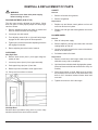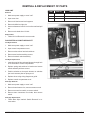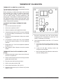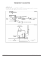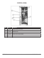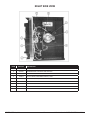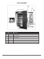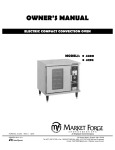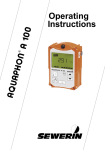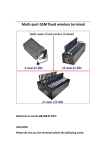
1
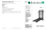
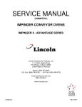
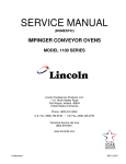
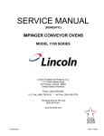
4200 & 4292
HALF SIZE ELECTRIC CONVECTION OVEN
PARTS AND SERVICE MANUAL
EFFECTIVE SEPTEMBER 23, 2014
Superseding All Previous Parts Lists.
The Company reserves the right to make substitution in the event that items specified are not available.
ERRORS: Descriptive and/or typographic errors are subject to correction.
MARKET FORGE INDUSTRIES
44 Lakeside Avenue, Burlington, Vermont 05401 USA Telephone: (802) 658-6600 Fax: (802) 860-3732
www.mfii.com
P/N 14-0394 Rev A (9/14)
TABLE OF CONTENTS
REVERSING THE DOOR SWING. . . . . . . . . . . . . . . . . . . . . . . . . . . . . . . . . . . . . . . . . . . . . . . . . . . . . . . . 3
REMOVAL & REPLACEMENT OF PARTS.. . . . . . . . . . . . . . . . . . . . . . . . . . . . . . . . . . . . . . . . . . . . . . . . 4
THERMOSTAT CALIBRATION. . . . . . . . . . . . . . . . . . . . . . . . . . . . . . . . . . . . . . . . . . . . . . . . . . . . . . . . . . . 7
TROUBLESHOOTING.. . . . . . . . . . . . . . . . . . . . . . . . . . . . . . . . . . . . . . . . . . . . . . . . . . . . . . . . . . . . . . . . . . 9
WIRING DIAGRAM.. . . . . . . . . . . . . . . . . . . . . . . . . . . . . . . . . . . . . . . . . . . . . . . . . . . . . . . . . . . . . . . . . . . . 11
ILLUSTRATED PARTS LIST
4200 OVEN.. . . . . . . . . . . . . . . . . . . . . . . . . . . . . . . . . . . . . . . . . . . . . . . . . . . . . . . . . . . . . . . . . . . . . . . . . . 12
CONTROL PANEL. . . . . . . . . . . . . . . . . . . . . . . . . . . . . . . . . . . . . . . . . . . . . . . . . . . . . . . . . . . . . . . . . . . . 14
RIGHT SIDE VIEW. . . . . . . . . . . . . . . . . . . . . . . . . . . . . . . . . . . . . . . . . . . . . . . . . . . . . . . . . . . . . . . . . . . . 15
DOOR ASSEMBLY. . . . . . . . . . . . . . . . . . . . . . . . . . . . . . . . . . . . . . . . . . . . . . . . . . . . . . . . . . . . . . . . . . . . 16
OVEN COMPARTMENT INTERIOR. . . . . . . . . . . . . . . . . . . . . . . . . . . . . . . . . . . . . . . . . . . . . . . . . . . . 17
SEPTEMBER 23, 2014
2
4200 & 4292 HALF SIZE ELECTRIC OVENS
REVERSING THE DOOR SWING
1. Remove door handle, P/N 08-5205, by removing
three slotted screws located on edge of handle.
7. Re-locate and install catch plate assembly at new location.
2. Loosen two upper hinge pin screws. Pin will drop into
door.
8. Hold door in new position and allow hinge pin to slide
out. Tighten two screws to hold pin in this position.
3. Remove door by tilting top of door outward while lifting door off of lower hinge pin.
9. Release the (new) top hinge pin and re-install door in
the new position. Push up hinge pin and tighten two
screws to hold upper hinge pin in place.
4. Remove catch plate assembly from face of oven.
10. Replace handle using hardware removed in step 1.
5. Remove four round head machine screws from opposite side of oven face.
11. Adjust door by resetting adjustment on catch plate
assembly.
6. Re-install on other side of oven face, the four round
head machine screws removed in step 5.
SEPTEMBER 23, 2014
3
4200 & 4292 HALF SIZE ELECTRIC OVENS
REMOVAL & REPLACEMENT OF PARTS
GASKET
WARNING
Removal
Disconnect oven from main power supply
before working on oven.
1. Remove all screws from gaskets.
2. Remove all gaskets.
DOOR ADJUSTMENT (OLD STYLE)
Replacement
The door was properly adjusted at the factory, if door
does not open or close properly adjust the ball plunger
catch as .follows:
1. Replace top and bottom metal gaskets on front off
oven liner and screw in place.
1. Remove adjusting wrench from back of manual and
insert in notches on sides of ball plunger.
2. Replace left and right side metal gaskets and screw
in place.
2. Loosen jam nut with wrench.
BLOWER WHEEL
3. Turn adjusting wrench left or right until ball plunger
engages in door striker plate for best operation.
Removal
1. Shut off main power supply.
4. Tighten jam nut with wrench while adjusting wrench is
still engaged in notches.
2. Remove baffle by placing hard under back end and
rotating baffle up and out.
5. Return adjusting wrench to back of manual.
3. Loosen set screws located in the center of the blower
wheel on the wheel hub.
OVEN DOOR
4. Pull blower wheel off of shaft.
New Style Door
Replacement
6. Remove lower screw (item 1) from upper hinge assembly of door.
1. Remove metal burrs and foreign matter from motor
shaft with emery cloth or sandpaper.
7. Loosen top screw (item 2) from upper assembly.
2. Lubricate blower wheel hub with high graphite grease.
(Remove blower and lubricate at least once every six
months).
8. Push upper hinge pin (item 3) into door.
9. Rotate top of door forward to clear upper frame.
3. Place blower wheel on shaft. Make sure set screws
are positioned over the flats on the shaft. Make sure
there is 3/16” clearance between blower wheel and
oven wall.
10. Pull up and out on door to remove.
4. Tighten set screws to 160 in-lbs torgue.
Old Style Door
Reverse above procedure being sure to put as many
washers under as there were before removal.
SEPTEMBER 23, 2014
4
4200 & 4292 HALF SIZE ELECTRIC OVENS
REMOVAL & REPLACEMENT OF PARTS
MOTOR
THERMOSTAT
Removal
Removal
1. Make sure main power supply is disconnected from
oven.
1. Make sure power supply to oven is off.
2. Open control compartment cover.
2. Remove baffle and blower wheel.
3. Remove right side panel.
3. Remove racks and rack supports from oven compartment.
4. Open control compartment cover.
4. Remove baffle.
5. Remove motor bolt access plate.
5. Disconnect thermocouple lead wires from circuit
board.
6. Remove four nuts and blots holding motor to motor
mount.
6. Unscrew thermocouple from oven liner.
7. Remove cover from wiring box mount on motor and
disconnect wires.
7. Pull thermocouple and wires through oven liner into
oven compartment and remove.
Replacement
8. Remove circuit board from bracket.
1. Revere procedure above.
Replacement
2. Check motor wiring to make sure blower turns clockwise when seen from front of oven.
1. Follow Thermostat Removal in reverse order.
HEATER ELEMENT
SWITCH
Removal
Removal
1. Make sure power supply to oven is off.
1. Make sure power supply to oven is off.
2. Remove right side panel.
2. Open control compartment cover.
3. Disconnect wire to switch.
3. Remove element terminal cover above motor and
disconnect wires.
4. Depress spring clips on switch and push forward.
4. Remove element plate and insulation spacer.
Replacement
5. Remove racks and rack supports from oven cavity.
1. Push switch into proper control panel opening until
spring clips catch.
6. Remove baffle.
2. Reconnect wire to switch.
7. Remove eight screws holding element assembly to
the oven wall.
3. Close control cover.
8. Remove elements.
Replacement
CONTACTOR
1. Follow Element Removal in reverse order.
Removal
1. Make sure power supply to oven is off.
2. Open control comportment cover.
3. Disconnect wire from appropriate component.
4. Unscrew fasteners of appropriate components and
remove.
Replacement
1. Attach components to mounting.
2. Replace and tighten fasteners.
3. Reconnect wires.
SEPTEMBER 23, 2014
5
4200 & 4292 HALF SIZE ELECTRIC OVENS
REMOVAL & REPLACEMENT OF PARTS
HIGH LIMIT
Removal
1. Make sure power supply to oven is off.
2. Open oven door.
ITEM
PART NO.
DESCRIPTION
1
08-6308
Reed switch (fan interlock)
2
99-6168
Reed switch mounting bracket
3
REF.
Marr connectors, two
3. Remove all shelves and rack supports.
4. Remove baffle from right sire.
5. Unscrew fasteners from Hi-Limit on liner wall and pull
out.
6. Remove wire leads from Hi-Limit.
Replacement
1. Follow Hi-Limit Removal in reverse order.
DOOR INTERLOCK SWITCH BRACKET
Old Style Removal
1. Make sure power supply to oven is off.
2. Open control compartment cover.
3. Remove wires to door interlock switches.
4. Remove two bracket retaining screws.
5. Remove interlock switch assembly.
Old Style Replacement
1. Insert long end of door activated plunger through hole
in left front side of control compartment.
2. Replace spring and switches in bracket and secure
switch assembly with two screws.
3. Position switches so that push buttons on switches
just touch actuator plate on plunger rod.
4. Replace wires using wiring diagram as guide.
5. Replace control compartment cover.
New Style Removal
1. Make sure power supply to oven is off.
2. Remove lower bottom trim, remove screws on end.
3. Remove screws from switch, to remove switch.
4. Remove marr connectors from leads, then remove
switch.
New Style Replacement
1. Follow New Style Interlock Switch Removal in reverse order.
SEPTEMBER 23, 2014
6
4200 & 4292 HALF SIZE ELECTRIC OVENS
THERMOSTAT CALIBRATION
THERMOSTAT CALIBRATION (OLD STYLE):
The thermostat is a device which automatically limits heat
input at or below the dial setting.
Before attempting to calibrate thermostat, make sure that
the thermostat is the cause of problems experienced.
Check for improper electrical service, incorrect mixes
over and under proofing, incorrect temperatures, and
warping pans. Thermostats are calibrated and sealed by
the original manufacturer before leaving their plant. Only
a qualified service person should make calibration adjustments, if they become necessary.
CALIBRATE ELECTRONIC THERMOSTAT (NEW
STYLE):
1. Set oven thermostat knob at 350°F.
2. Allow oven to preheat to 350°F.
3. Observe temperature with digital thermometer.
4. If temperature goes above 350°F turn set pot labelled
HI (on circuit board) counterclockwise. % turn should
be sufficient.
5. Allow time for oven temperature to drop, then recheck
temperature.
7. Record the temperature when the ele-ment indicator light goes off. If a temperature of 345°-355° is attained, no calibration is necessary .
6. If temperature is below 350°F turn set pot labelled
HI (on circuit board) clockwise.+/-5°F turn should be
sufficient.
8. If the temperature differs more than +/- 5°F from the
dial setting:
7. Repeat steps 4 to 7 until oven temperature stabilizes
at 350°F+/- 5°F
a. Pencil mark the knob pointer position as a reference point on the control panel next to the dial
plate
8. Apply Glyptol or Duco Cement to set pot to prevent
rotation.
b. Loosen the dial plate mounting screws only
enough to move the plate.
THERMOSTAT DIAL PLATE CALIBRATION (NEW
STYLE):
c. Move the dial plate until calibration matches thermometer reading (350°F).
1. Clamp thermocouple sensor in the center of the middle rack in compartment.
2. Pass the thermocouple sensor wire through the door
gasket and close the door.
3. Plug the sensor lead into the pyrometer.
4. Set the oven power switch to ON.
5. Set the thermostat knob to 350° (191°C).
6. Allow the oven to warm up for a minimum of (3) three
ON/OFF cycles.
SEPTEMBER 23, 2014
7
4200 & 4292 HALF SIZE ELECTRIC OVENS
THERMOSTAT CALIBRATION
CONTROL BOARD
NOTE: New style board CANNOT BE CALIBRATED. Check thermocouple for fault in temperature
control. If thermocouple is good, replace temperature control board.
SEPTEMBER 23, 2014
8
4200 & 4292 HALF SIZE ELECTRIC OVENS
TROUBLESHOOTING
PROBABLE CAUSE
REMEDY
Convector fan fails to operate.
1. Power to oven is off.
1. Locate external circuit breakers for power and place in ON
position.
2. ON-OFF switch off.
2. Place in ON position.
3. Oven door open.
3. Close door.
4. Faulty cool down switch ON-OFF switch, door 4. Test each component and connecting wire, replace as reswitch, fan motor, wiring.
quired.
Oven will not heat with thermostat at maximum setting, fan operating.
1. Faulty thermostat wiring.
1. Test thermostat and connecting wiring. Replace as required.
2. Thermostat contacts or coil faulty.
2. Replace thermostat.
Indicator light fails to light with thermostat set, fan operating, oven hot.
1. Indicator light burned out.
1. Replace light.
2. Faulty wiring.
2. Check wiring and repair as needed.
Erratic oven temperature.
1. Faulty thermostat operation.
1. Recalibrate or replace as required.
Uneven heating.
1. One or more heating elements inoperative.
SEPTEMBER 23, 2014
1. Check wiring to elements; check for burned out elements.
Replace as required.
9
4200 & 4292 HALF SIZE ELECTRIC OVENS
TROUBLESHOOTING
WIRING
All the electrical components of the model 4200 (ON-OFF
switch, door switch, thermostat control, contactors, fan
motor, and indicator light) are connected to each other by
wiring shown on page 5. If all the electrical components
are operating correctly and the incoming power has been
checked, but the unit fails to operate, the fault lies in the
wiring.
Using an ohmmeter, wiring continuity between the connections, shown in the wiring diagram is readily verified.
This is best done in stages, removing only those wires
required for each continuity check. As each lead is replaced, it should be checked for evidence of corrosion
and cleaned if necessary. All leads must be tightly attached to provide a good electrical connection.
ELECTRICAL FAULT ISOLATION GUIDE
FAILURE
FAULT LOCATION
1. Incoming power
Oven will not operate when the thermostat is set.
2. Door switch
3. Thermostat control
4. ON-OFF switch
5. Cool down switch
6. Contactor
7. Wiring
1. Thermostat control
Intermittent operation of heaters.
2. Contactor coil
3. Wiring
1. Cool down switch
Convector fan fails to operate.
2. ON-OFF switch
3. Door Switch
4. Fan motor
5. Wiring
1. Indicator light
Indicator light off, heater under power.
2. Wiring
3. Heating elements
Uneven heating.
4. Wiring
1. Check switch
(Elements Only) fails to come on.
2. Check hi-limit switch
3. Check wiring
SEPTEMBER 23, 2014
10
4200 & 4292 HALF SIZE ELECTRIC OVENS
WIRING DIAGRAM
SEPTEMBER 23, 2014
11
4200 & 4292 HALF SIZE ELECTRIC OVENS
4200 OVEN
SEPTEMBER 23, 2014
12
4200 & 4292 HALF SIZE ELECTRIC OVENS
4200 OVEN
ITEM
PART NO.
2
08-6459
THERMOSTAT KNOB
3
09-6440
RED PILOT 250V
4
09-7231
SWITCH DPDT 250V, 10 AMP, RED, ON-OFF SWITCH
5
09-7244
SWITCH DPDT 250V, 10 AMP, BLUE, BLOWER SWITCH
6
09-7235
SWITCH DPDT 250V, 10 AMP, WHITE, COOL DOWN SWITCH
7
09-7231
SWITCH DPDT 250V, 10 AMP, RED, HEATING ELEMENTS ONLY
8
08-5839
THERMOSTAT DECAL
10
99-6098
SIDE GASKET
11
99-6101
TOP AND BOTTOM GASKET
12
10-5453
BLOWER WHEEL
13
09-7259
THERMOCOUPLE
14
09-7241
HEATING ELEMENT, OUTER, 280V-2500W, 220V-2800W (EXPORT)
14A
09-7242
HEATING ELEMENT, OUTER, 230V-2571W, 240V-2800W
15
09-7336
HEATING ELEMENT, INNER, 280V-2500W, 220V-2800W
15A
09-7337
HEATING ELEMENT, INNER, 230V-2571W, 240V-2800W
16
99-6102
HEATING ELEMENT BRACKET
17
99-6130
BAFFLE SUPPORT
18
99-5051
BOTTOM TRIM
19
99-5064
TOP TRIM
20
99-6107
OVEN INTERIOR COVER PLATE
21
09-5267
60 MINUTE TIMER KNOB
22
08-6351
HI-LIMIT THERMOSTAT
SEPTEMBER 23, 2014
DESCRIPTION
13
4200 & 4292 HALF SIZE ELECTRIC OVENS
CONTROL PANEL
ITEM
PART NO.
DESCRIPTION
1
10-6293
2
REF.
3
10-6649
TERMINAL BLOCK
4
10-5551
GROUND LUG
5
99-5822
CONTROL CIRCUIT WIRE HARNESS
6
10-5943
CONTACTOR, 240V, 40 AMP, 50/60 HZ, 208 & 240V
7
08-6355
TEMPERATURE CONTROLLER, 208 OR 240V
SEPTEMBER 23, 2014
60 MINUTE TIMER, 240V, 50/60 HZ
POTENTIOMETER, PART OF THERMOSTAT 08-6356
14
4200 & 4292 HALF SIZE ELECTRIC OVENS
RIGHT SIDE VIEW
ITEM
PART NO.
1
09-7230
BLOWER MOTOR, 208/230V, 1/4 HP, 2 SPEED
2
08-6355
TEMPERATURE CONTROLLER, 208-240V
3
10-6649
TERMINAL BLOCK
4
10-6874
S.P.S.T. RELAY, FOR REED SWITCH, 240V
5
10-5943
CONTACTOR, 208V, 40 AMP, 50/60 HZ, 208V & 240V
6
99-6108
HEATING ELEMENT COVER PLATE
6A
99-6109
HEATING ELEMENT COVER GASKET
7
99-6140
MOTOR BRACKET
8
09-6516
SIREN AUDIO ALERT, 120V
SEPTEMBER 23, 2014
DESCRIPTION
15
4200 & 4292 HALF SIZE ELECTRIC OVENS
DOOR ASSEMBLY
ITEM
PART NO.
1
08-5205
DOOR HANDLE ASSEMBLY
2
99-5169
CATCH, MAGNETIC
3
99-6115
SPACER CATCH
4
99-6170
DOOR ASSEMBLY
5
99-6153
HINGE PIN
6
99-6154
HINGE PIN PLATE
99-6098
DOOR GASKET (NOT SHOWN)
99-6101
DOOR GASKET TOP (NOT SHOWN)
SEPTEMBER 23, 2014
DESCRIPTION
16
4200 & 4292 HALF SIZE ELECTRIC OVENS
OVEN COMPARTMENT INTERIOR
Sorry - no drawing available
PART NO.
DESCRIPTION
99-5025
BAFFLE
99-5057
RACK SUPPORTS
99-5056
RACKS
99-5052
EXTERIOR TOP PANEL
99-5058
EXTERIOR REAR PANEL
99-5020
RIGHT SIDE ACCESS PANEL
99-5035
LEFT SIDE PANEL
99-6176
28” HIGH STAND
99-6177
18” STACKED KIT WITH STAND
SEPTEMBER 23, 2014
17
4200 & 4292 HALF SIZE ELECTRIC OVENS