1
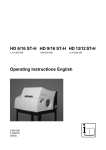
Operating Instructions Measurable success by Sewerin equipment Congratulations. You have chosen a quality instrument manufactured by Hermann Sewerin GmbH. Our equipment will provide you with the highest standards of performance, safety and efficiency. They correspond with the national and international guide-lines. Please read and understand the following operating instructions before using the equipment; they will help you to use the instrument quickly and competently. If you have any queries we are available to offer advice and assistance at any time. Yours Hermann Sewerin GmbH Sewerin USA LLC Robert-Bosch-Straße 3 33334 Gütersloh, Germany Tel.:+49 5241 934-0 Fax:+49 5241 934-444 www.sewerin.com [email protected] 2835 Haddonfield Road Pennsauken, NJ 08110-1108 Phone: +1 215-852-8355 Fax: +1 856-662-7070 www.sewerin.net [email protected] SEWERIN SARL Sewerin Ltd 17, rue Ampère – BP 211 67727 Hoerdt Cedex, France Tél. :+33 3 88 68 15 15 Fax :+33 3 88 68 11 77 www.sewerin.fr [email protected] Hertfordshire UK Phone: +44 1462-634363 www.sewerin.co.uk [email protected] SEWERIN IBERIA S.L. Sewerin Sp.z o.o. Centro de Negocios Eisenhower Avenida Sur del Aeropuerto de Barajas 24, Ed. 5 Of. 2C 28042 Madrid, España Tel.:+34 91 74807-57 Fax:+34 91 74807-58 www.sewerin.es [email protected] ul. Annopol 3 03-236 Warszawa, Polska Tel.: +48 22 519 01 50 Fax: +48 22 519 01 51 Tel. kom.+48 501 879 444 +48 608 01 37 39 www.sewerin.com [email protected] Illustration AQUAPHON A 100 Digital display Gaunlet key Analog display Speaker symbol Headphone socket Loudspeaker Socket for probes Battery symbol Comment line Mikrophone key AQUAPHON® A 100 Small digital display Charging status display / Volume display Cusor keys Magnifying-glass and on/off key Hz key Light key Operating Instructions AQUAPHON® A 100 17.11.2008 – V8.X – 104194 – en Symbol explanation CAUTION! This symbol warns of dangers that may threaten the safety of the user or maty damage or destroy the product. Note: This symbol flags information and hints extending beyond the actual operation of the product . Contents Page 1 General .....................................................................................1 1.1 1.2 1.3 Warranty ....................................................................................1 Intended use .............................................................................2 General notes............................................................................2 2 Function description ...............................................................3 2.1 2.2 Water leak detection..................................................................3 Acoustic pipeline location ..........................................................3 3 Use ............................................................................................4 3.1 3.1.1 3.2 3.3 3.4 3.4.1 3.5 Switching on and off ..................................................................4 Manual probe selection ..........................................................5 Adjusting the display contrast ...................................................5 Charging equipment ..................................................................6 Charging ....................................................................................6 Self-discharge ........................................................................7 Connecting the headphones .....................................................8 4 Water leak detection ...............................................................9 4.1 4.1.1 4.1.2 4.1.3 4.1.4 4.1.5 4.1.6 4.1.7 4.1.8 4.2 4.2.1 4.2.2 4.2.3 4.2.4 4.2.5 4.2.6 4.3 4.3.1 4.3.2 Displays .....................................................................................9 Analog display ........................................................................9 Digital display .........................................................................9 Small digital display................................................................9 Speaker symbol ...................................................................10 Volume display .....................................................................10 Battery symbol .....................................................................10 Comment line ....................................................................... 11 Basic amplification ............................................................... 11 Key functions ........................................................................... 11 Microphone key .................................................................... 11 Gauntlet key .........................................................................12 Hz key ..................................................................................12 Cursor keys ..........................................................................14 Light key ...............................................................................14 Magnifying-glass and on/off key...........................................15 Probe overview .......................................................................16 Ground microphone BO-4 ....................................................16 Ground microphone 3P-4 .....................................................16 I Contents Page 4.3.3 4.3.4 4.4 4.5 4.6 4.7 4.8 4.9 Carrying rod H-4...................................................................16 Test rod T-4 ..........................................................................17 Switching on and off ................................................................18 Sound-protection function .......................................................19 Preliminary location .................................................................19 Pin pointing .............................................................................23 Individual settings ....................................................................25 Factory settings (reset) ...........................................................27 5 Brief instruction ....................................................................28 5.1 Brief instruction on water leak detection .................................28 6 Malfunctions ..........................................................................31 7 Specifications ........................................................................33 8 Accessories ...........................................................................34 8.1 8.2 Accessories for water leak detection.......................................34 General accessories ...............................................................34 9 Hints on Disposal ..................................................................35 Annexe ................................................................................................36 Declaration of Conformity ......................................................................36 Record of changes ................................................................................37 Index ......................................................................................................38 II 1 General 1 General 1.1 Warranty Hermann Sewerin GmbH bears no liability for damage attributable to non-compliance with these instructions. The terms of warranty and liability of the conditions of sale and delivery of Hermann Sewerin GmbH are not extended by the above. This product may only be used after the operating instructions have been read and understood. This product was developed for qualified skilled personnel in public utility companies. The device must only be commissioned after respective introduction. This product may only be used for its designated purpose. This product is destined for industrial and commercial applications. Repair work may only be carried out by appropriately trained persons. Changes and modifications to the product may only be carried out with the consent of Hermann Sewerin GmbH. Unauthorised modifications to the product render the warranty of the producer null and void. Only accessories from Hermann Sewerin GmbH may be used with this product Only replacement parts approved by Hermann Sewerin GmbH must be used for repairs. We reserve the right to make technical modifications in the interests of further development. Please comply with general safety rules in addition to these instructions! 1 1 General 1.2 Intended use The A 100 is a instrument for electro-acoustic water leak detection and acoustic pipeline location Note: This operating instructions describes the functions of software version 8.X. Future changes are subject to modification! 1.3 General notes In order to ensure the correct functioning of the devices, the following requirements must be complied with: – Devices must not be dipped or immersed. – Display and keyboard must not be scratched. – Devices must not be dropped. – Devices must not be used as supports. The allowed operating temperature range is -10 °C … +50 °C. The allowed storage temperature is -25 °C … +70 °C. If additional devices are used (e.g. generators), the corresponding operating manuals must be complied with. 2 2 Function description 2 Function description 2.1 Water leak detection The A 100 is used in combination with various microphones (listed in the „Accessories“ section) for the electro-acoustic detection of water-leaks. When a pressurised pipeline develops a leak, water flows through it into the surrounding soil at high speed. Consequence: The pipeline material vibrates at the exit point. This vibration is transmitted by the pipe, with the result that it can be picked up even at remote contact points (valves and the like). This structure-borne noise is rendered audible by the A 100. The water jet - and the pipe, in the vicinity of the leak - also induce vibration in the soil. This is transmitted to the surface, where it can be picked up as ground-borne noise. Even with electro-acoustic leak detection the human ear retains its importance. Suitable practice enables noises of different types. and tones to be compared, and leak noise distinguished from extraneous, unrelated noise. 2.2 Acoustic pipeline location Plastic lines cannot be located by the classical electromagnetic method because they do not conduct electricity. The acoustic method of pipeline location uses a different principle: the lines transmit mechanical vibration better than the surrounding earth. If suitable vibrations are applied to the line, they are transmitted along its length and through the earth to its surface, and can then be located there with an ground microphone and receiver with headsets according to the water leak detection principle. As with water leak detection, the line is in the place where the greatest intensity is found. Fibrous-cement and metallic pipes can also be located in this way. If you wish to detect the lines acoustically, follow the operating instructions for the vibration emitter (eg, COMBIPHON). Proceed as with for water leak detection. The A 100 also offers an additional mode to assist in detecting lines (see section 4.2.1). 3 3 Use 3 Use 3.1 Switching on and off Plug a probe into the appropriate input . Probe connection: input 1 A brief signal tone sounds. The software version appears in the display. The charge status of the rechargeable batteries appears in the display. The type of probe plugged in is automatically determined. 1 The probe type briefly appears in the display. If the probe type is not automatically identified it can be selected manually (see section 3.1.1). If a microphone has been plugged in, the bandpass currently set for the frequency filter is briefly displayed. 4 3 Use The layout of the display depends on the used probe. The measurement process may be started. To switch off, unplug the probe from the input. 3.1.1 Manual probe selection If the probe is not automatically identified (if it is an old model, for example), it can be selected manually: Hold down the microphone key. Plug in the probe.The „>“ symbol appears on the left of the bottom text line and the name of the probe that can be selected, e.g. „M01“ in the middle. Pressing the cursor keys switches between possible probes. Pressing the magnifying-glass key displays the selected probe. 3.2 Adjusting the display contrast The display contrast can be adjusted as follows: Hold down the light key. Press the cursor-down key to reduce the contrast. Press the cursor-up key to increase the contrast. 5 3 Use 3.3 Charging equipment When fully charged the instruments have a maximum operating time of approx. 12 hours. To charge an instrument you need the charging station HS 1,2 A (see fig.), which can be used either in the workshop or in the emergency vehicle. The charging station has the following sockets on its side: AC/DC adapter M4, 100 … 240 V~ Car charging cable M4 3.4 Charging Note: Charging the accumulator only within temperature range 0 ... 45 °C. Switch off the instrument and plug it into the charging station. The following (or similar) appears in the display: The instrument now has 5 operating hours (= 5 bars) left. It will take another 3 hours to be fully charged. The actual operating time depends on the accumulators’ condition (age ...) and operation (light, volume ...) charging time takes max. 4 hours. When it is fully charged all the bars appear and the number display disappears. 6 3 Use You can leave the instrument in the charging station until you need it again. If you have a case for your A 100, it can be charged inside. Connect cable to the charging station inside the case. Connect the plug-in AC/DC adapter M4 or car charging cable M4 to socket 2. 3.4.1 Self-discharge If the instrument is not placed in the charging station HS 1,2 A when switched off the NiMH-accumulator will self-discharge, which is considered when displaying the remaining operating time. After no more than 30 days the instrument will indicate zero operating hours, and it must be recharged. 7 3 Use 3.5 Connecting the headphones A 100 are fitted with a speaker (1). Such produces the confirmation and alarm signals. There is, furthermore, a specific tone for pipeline location. During water leak detection no leak noise is emitted over the speaker: headphones must be used. Switching from speakers to headphones: 1 2 Plug the headphones jackplug into socket 2. The speaker is switched off automatically; sound is output to the headphones. When the headphones are unplugged the sound is once more output to the speaker. 8 4 Water leak detection 4 Water leak detection 4.1 Displays 4.1.1 Analog display The analog display indicates the current reading. 4.1.2 Digital display The digital display indicates the smallest value measured during a single measurement. In the „MAX“ mode, the digital display always shows the greatest measured value. In „MAX“ mode you can switch by holding the micro key for 3 seconds (only with microphones with cable connection, not with radio microphones). 4.1.3 Small digital display For the purposes of comparison the small digital display always indicates the precedent value measured. 9 4 Water leak detection 4.1.4 Speaker symbol The speaker symbol indicates that the A 100 headphones are activated. 4.1.5 Volume display The volume display indicates the volume set. If the bar on the extreme left is shown in reverse video, the volume is low; if the bar on the extreme right is shown in reverse video, the volume is maximum. The volume can be adjusted with the cursor keys. 4.1.6 Battery symbol The battery symbol appears about 15 minutes before the battery runs out. In case the accumulator volume drops further, the instrument automatically switches off to protect the accumulator. 10 4 Water leak detection 4.1.7 Comment line Various possible settings and parameters are displayed in the comment line. The filter setting is shown here, for example. 4.1.8 Basic amplification Basic amplification is useful for adapting to extreme situations. The higher the basic amplification, the louder the noise in the headphones. The values 10, 100 or 1000 appear in the display. Basic amplification can be altered with the magnifying-glass key (see section 4.2.6). 10 = high amplification 100 = medium amplification 1000 = low amplification 4.2 Key functions 4.2.1 Microphone key Pressing the microphone key activates the A 100. Pressing it again deactivates it. 11 4 Water leak detection Modus „MAX“ If you hold down the micro key for 3 seconds, you can switch to „MAX“mode. This mode helps with acoustic line detection. Instead of minimum values, only max values are shown in this mode (only with microphones with cable connection, not with radio microphones). 4.2.2 Gauntlet key Pressing the gauntlet key activates the A 100. Depending on the options selected in the set-up menu it is deactivated either by releasing the gauntlet key or by pressing it again. 4.2.3 Hz key The Hz key is used to alter the frequency-filter setting. The filter bandpass - which is a least 300 Hz wide - can be set anywhere between 1 Hz and 10 kHz. Pressing both cursor keys at once resets the bandpass to its default setting, which depends on the probe. 12 4 Water leak detection Different leak noises can be heard best in different frequency ranges, and two people may hear the same noise differently. To optimise acoustic perception a bandpass can be set.In this case only a particular frequency range is fed to the headphones. The best setting can be found by experiment, or alternatively the A 100 can search for it automatically. Setting the frequency range manually Press the Hz key. The most recently set limits are displayed; the lower filter limit flashes. The cursor keys change the lower filter limit step by step. Press the Hz key again. The upper filter limit flashes. The cursor keys change the upper filter limit step by step. Press the Hz key again. The filter limits are saved. 13 4 Water leak detection Automatic search for the best frequency range The A 100 has a filter-optimisation function that automatically searches for the best frequency range. It should not be activated if there is any significant extraneous noise, and the leak noise - particularly groundborne noise - should already be audible. Press the Hz key until a clearance tone sounds. The A 100 takes a „noise sample“ and analyses it. While analysis is under way the display indicates various frequency ranges. The noise produced by the filter values displayed can be heard over the headphones. The A 100 selects the frequency range in which the leak noise is especially clear. 4.2.4 Cursor keys The cursor keys are used to adjust the volume of the speaker or headphones. The volume setting is shown in the display by a bar in reverse video. 4.2.5 Light key The light key switches the display illumination on and off. It switches off automatically after about 2 minutes. 14 4 Water leak detection) 4.2.6 Magnifying-glass and on/off key The analog display indicates the relative noise level. The display can be adapted to prevailing conditions to make a change in the display from one measurement point to another easier to detect. This adaptation switches the analog display (instantaneous value) between scale values 10, 100 and 1000 and alters basic amplification for the headphones. 10 = high sensitivity, high amplification 100 = medium sensitivity, medium noise amplification 1000 = low sensitivity, low noise amplification Automatic adjustment takes place to maintain the ratio between the current delayed-action value and the instantaneous value. Press the microphone key. The A 100 is activated. Press the magnifying-glass key. The sensitivity of the analog display is altered. The current sensitivity setting is shown above and to the right of the display. 15 4 Water leak detection 4.3 Probe overview 4.3.1 Ground microphone BO-4 The ground microphone BO-4 is used to locate leaks beneath stabilised surfaces. 4.3.2 Ground microphone 3P-4 The ground microphone 3P-4 is used to locate leaks beneath unstabilised surfaces. An earth spike can be screwed onto it for use in soft ground. Its 3 feet guarantee stability at all times. 4.3.3 Carrying rod H-4 The carrying rod can be used with both ground microphones. The BO-4 or 3P-4 microphone is screwed onto its lower end. 16 4 Water leak detection 4.3.4 Test rod T-4 The test rod is used for preliminary leak location. The test rod is placed in contact with valves on the line under investigation. 17 4 Water leak detection 4.4 Switching on and off Put the microphone jack-plug into socket 1 on the A 100. The A 100 switches on. 1 If the A 100 does not switch on, press the on/off key. One of the following displays briefly appears in the display: for test rod or for ground microphone or for other microphone types. To switch off, unplug the probe from socket 1. 18 4 Water leak detection 4.5 Sound-protection function The A 100 incorporates a soundprotection function. With a sudden loud noise the sound in the headphones is immediately muffled. If the sound gets even louder the headphones are switched off. Once this noise source has ceased the A 100 reverts to normal operation. The sound-protection function ensures that no excessive sound pressure reaches the ears. This headphones symbol appears in the comment line when the sound-protection function is activated. Caution! Only Sewerin headphones should be used, as these are adjusted to the A 100. The threshold at which the sound-protection function is triggered can be adjusted: see section 4.8 „Individual adjustments“. 4.6 Preliminary location Structure-borne sound is transmitted a very long way by metallic pipes, which makes the test rod very effective for preliminary location. Connect the headphones to the A 100. Connect the test rod to the A 100. Place test rod on the first measurement point. 19 4 Water leak detection Activate the A 100 with the gauntlet key or the microphone key. A speaker symbol appears in the display during measurement. The analog display indicates the current measurement volume. The noise can be heard by the headphones. During this measurement the digital display indicates the smallest value measured. The small digital display indicates the smallest value measured during the previous measurement. (This value is 0 after first measuring.) The smallest measured value is shown in the analog display in reverse video during the measurement. To deactivate the A 100 release the gauntlet key or press the microphone key again. If the A 100 is not deactivated when the gauntlet key is released, the function of the gauntlet key has been changed (see section 4.8). In this event press the gauntlet key again. Place the test rod on the next measurement point and proceed exactly as described above. The previously measured value now appears in the small digital display for the purposes of comparison. 20 4 Water leak detection In water leak detection the display will be similar to that shown in the illustration above. The noise is loudest near the leak and quieter further away. On the left: the analog display indicates about 30%: this is the instantaneous noise value. However, the analog display often fluctuates substantially because of changing ambient noise. Even a trend can be hard to recognise. This is why the large digital display (figure 16) indicates the smallest noise value measured at this point so far (the current delayedaction value). Even if ambient noise grows louder, this display is unaffected - while if it grows quieter the display falls further. The figure 16 is also shown in the analog display as a segment in reverse video. The small digital display indicates “0”: as yet there is no value in memory. Centre: the analog display indicates about 60%. The large digital display (figure 38) indicates a value greater than the left-hand measurement point. This is an indication that the leak is closer. The small digital display now indicates “16”: it reminds you of the result from the last measurement point (last delayed-action value). This makes it easier to decide whether you have not yet reached the leak or have already gone past it. 21 4 Water leak detection Right: the current delayed-action value has fallen because the leak is further away. The last delayed-action value, “38”, provides us a further comparison. The following illustration shows how a leak noise overlaid by fluctuating extraneous noise is shown in the display. 22 4 Water leak detection 4.7 Pin pointing Non-metallic pipe materials do not transmit structure-borne sound as well. Therefore checking at the valves is not enough. The sections between valves must also be checked with a ground microphone. Listening to the surface of the ground at short intervals enables the leak to be located without digging. Here, too, the A 100 provides a precise optical comparison of the noise intensities. The above illustration, for example, shows how the display changes when passing a leak. Connect the ground microphone to the A 100. Place the microphone on the ground. Activate the A 100 with the gauntlet key or the microphone key. A speaker symbol appears in the display during measurement. The analog display indicates the current measurement volume. 23 4 Water leak detection The current noise can be heard through the headphones. The digital display indicates the smallest value measured. The small digital display indicates the previously-measured value. For the first measurement this value is 0. The smallest measured value is shown in the analog display in reverse video. To deactivate the A 100 release the gauntlet key or press the microphone key again. If the A 100 is not deactivated when the gauntlet key is released, the function of the gauntlet key has been changed (see section 4.8). In this event press the gauntlet key again. Place the ground microphone on the next measurement point and proceed exactly as described above. The previously measured value now appears in the small digital display for the purposes of comparison. Use the ground microphone to check the area of the section where the leak is thought to be. The illustration on the previous page shows an example of the display when crossing a leak. 24 4 Water leak detection 4.8 Individual settings On the A 100 various settings can be freely selected and permanently saved. The set-up table on the next page highlights the various possibilities. This is a list of settings that you can alter and save. First of all please switch-on the instrument. Hold down the microphone key. Press the on/off key. „ELWset“ appears in the comment line. The microphone key calls the menu items one after another. The cursor-up key alters the status of the selected menu. After the last menu the „save“ message appears. The cursor-up key saves the current settings and terminates the function. Notes: The ear protection function should be set to „low level“ only with low surrounding noise so that is already activated with moderate noise levels. In situations with high noise, such level should be set to option (1), factory settings. In special cases, the setting option (2) may be used. The ear protection function will then only be activated in case of very loud noise levels. To avoid that the ear protection function is activatet too often and impairs locating the leak, the headphones’ volume may not be set too loud. 25 4 Water leak detection ELW - setup table Menu Description number 1 Condition Condition Condition (0) (1) (2) The gauntlet key (item 1) is a key which does or does not stay down when pressed without* with / 2 Quit tone on pressing button on* off / 3 sound-protection function operates at low threshold middle threshold* high threshold 4 Basic amplification low middle* high 5 headphones switch off completely yes* no / ( * = factory setting) Example: If the comment line contains „No 3 0“, the sound-protection function operates at the low threshold. Basic amplification is useful for adapting to extreme situations. The higher the basic amplification, the louder the noise in the headphones at a given volume setting. Pressing the magnifyingglass key is a convenient way to alter basic amplification. If you do not want the headphones to switch off completely when the sound-protection function is triggered by loud noises, only heavily muffled, select „switch off headphones completely: No“. This means that the user will not lose all ambient noise while using the hearing-protection headphones. An orientation, for example in traffic, is limited possible. 26 4 Water leak detection 4.9 Factory settings (reset) The factory settings (e.g. filter settings) can be restored as follows. Plug in a microphone jackplug while holding down the light key. „Reset“ appears in the bottom text line for about 2 seconds. 27 5 Brief instruction 5 Brief instruction 5.1 Brief instruction on water leak detection Preliminary location Connect the headphones to the A 100. Connect the test rod to the A 100. Place test rod on the first measurement point. Activate the A 100 with the gauntlet key or the microphone key. A speaker symbol appears in the display during measurement. The analog display indicates the current measurement volume. The noise can be heard by the headphones. During this measurement the big digital display indicates the smallest value measured. During this measurement the small digital display indicates the smallest value of the precedent measurement. For the first measurement this value is 0. During this measurement the smallest measured value is shown in the analog display in reverse video. To deactivate the A 100 release the gauntlet key or press the microphone key again. If the A 100 is not deactivated when the gauntlet key is released, the function of the gauntlet key has been changed (see section 4.8). In this event press the gauntlet key again. 28 5 Brief instruction Place the test rod on the next measurement point and proceed exactly as described above. The previously measured value now appears in the small digital display for the purposes of comparison. 29 5 Brief instruction Pin pointing Instead of a test rod connect a ground microphone to the A 100. Place the microphone on the ground. Activate the A 100 with the gauntlet key or the microphone key. A speaker symbol appears in the display during measurement. The analog display indicates the current measurement volume. The current noise can be heard through the headphones. The digital display indicates the smallest value measured. The small digital display indicates the previously-measured value. For the first measurement this value is 0. The smallest measured value is shown in the analog display in reverse video. To deactivate the A 100 release the gauntlet key or press the microphone key again. If the A 100 is not deactivated when the gauntlet key is released, the function of the gauntlet key has been changed (see section 4.8). In this event press the gauntlet key again. Place the ground microphone on the next measurement point and proceed exactly as described above. The previously measured value now appears in the small digital display for the purposes of comparison. Use the ground microphone to check the area of the section where the leak is thought to be. 30 6 Malfunctions 6 Malfunctions Malfunctions of the device are indicated through an error message on the display. An F and an error code will be displayed. Error code 10 40 41 52 100 Description Error be- Remedy haviou A 100 not recognised self-lock- Switch deing vice back on, SEWERIN service Temperature at battery to self-lock- Improve high for charging (> 45°C) ing device surroundings, SEWERIN service Temperature at battery to self-lock- Improve low for charging (< 0°C) ing device surroundings, SEWERIN service Data flash error occurred self-lock- Switch deing vice back on, SEWERIN service Probe not recognised by self-lock- Switch device ing device back on, manually select probe, SEWERIN service 31 6 Malfunctions 32 Error code 110 Description 210 Communication error with CODEC 239 DSP error in boot program 240 DSP error when loading firmware 241 Communication error with DSP No probe detected by device Error be- Remedy haviou self-lock- Switch ing device back on, manually select probe, SEWERIN service Self-reSwitch desetting vice back on, SEWERIN service self-lock- Switch deing vice back on, SEWERIN service self-lock- Switch deing vice back on, SEWERIN service Self-reSwitch desetting vice back on, SEWERIN service 7 Specifications 7 Specifications Fab-no.: A 100 037 11 Transmission bandwidth (A 100): 1 – 10000 Hz Filter, adjustable: steps of 50, 500 and 1000 Hz Filter, minimum bandwidth: 300 Hz Power supply: built-in rechargeable accumulator (NiMH) integral automatic charging/ buffer system Displayed battery status Operating time approx. 12 hours Type of protection in operation: IP65 Weight: approx. 1,0 kg Approximate dimensions: (W x H x D): 12.5 × 18 × 6.5 cm Temperature range: operation storage -10 °C – +50 °C -25 °C – +70 °C 33 8 Accessories 8 Accessories 8.1 Accessories for water leak detection Piezo-Test rod T-4, with screwed on tip. Ground microphone BO-4 With sound-proofed against extraneous noise, especially suitable for stabilised surfaces. Carrying rod H-4 For ground microphones BO-4 and 3P-4 Ground microphone 3P-4 with tripod, for both stabilised and unstabilised surfaces, with screw-on 20-cm measuring spike. Test rod extension 60 cm needed for listening to valves in shafts Valve adapter Gate valve adapter Piezo-microphone EM30 especially suitable for use in buildings. 8.2 General accessories Headphones stereo Charging station HS 1.2 A Case A 100 Case with foam inlay, special transport protection, incorporated pockets for accessories, device may be charged inside the case. AC/DC adapter M4 Car charging cable M4 Carrying system Triangel adjustable upholstered back belt Carrying system Cross Belt Carrying system „Cross Belt“, 2 adjustable straps with diagonal attachment points. The straps cross over at the back for extra comfort. 34 9 Hints on Disposal 9 Hints on Disposal The disposal of instruments and accessories is governed by the European Waste Catalogue (EWC). Type of Waste Corresponding EWC Code Instrument 16 02 13 Battery, accu 16 06 05 Old Instruments Old instruments can be returned to Hermann Sewerin GmbH. We will arrange the qualified disposal free of charge through certified specialists. 35 Annexe Konformitätserklärung / Declaration of Conformity Tragbares Gerätebezeichnung: Tragbares Leitungssuchgerät Leitungs- und Wasserlecksuchgerät Type of Product: portable battery operated pipelocator Tragbares Wasserlecksuchgerät portable batteryoperated pipe locator and water leak detector portable batteryoperated water leak detector Geräte-Typ: Product Name: FERROPHON EL AQUAPHON AF 100 AQUAPHON A 100 Fabrikations-Nr.: Fabr. No.: 035 11 xxxx 036 11 xxxx 037 11 xxxx Hiermit erklären wir, dass oben genanntes Produkt mit der/den folgenden Norm(en) oder normativen Dokument(en) übereinstimmt. Bei einer mit uns nicht abgestimmten Änderung des Produkts verliert diese Erklärung ihre Gültigkeit. We hereby declare that the above product complies with the following norms or standardized directives. In the event of any modification of this product which has not been authorized by us, this declaration becomes invalid. Norm(en)/Norm(s): DIN EN 61000-6 – 2 EMV – Fachgrundnorm Störfestigkeit Generic Immunity Standard DIN EN 61000-6 – 4 EMV – Fachgrundnorm Störaussendung Generic Emission Standard Gemäß den Bestimmungen der Richtlinie(n)/The unit complies with: 89/336/EWG EG-Richtlinie: Elektromagnetische Verträglichkeit EG-Directive: Electromagnetic Compatibility 92/31/EWG Änderung dazu/amendment to above 93/68/EWG Änderung dazu/amendment to above Gütersloh, den 17.02.2006 HERMANN SEWERIN GMBH (Geschäftsführer/Managing Director) 36 Annexe Record of changes Version 4.2 Display: set to sensitivity ranges 1 … 10, 1 … 100, 1 … 1000, switch via magnifying-glass key Factory settings: sound protection functions only active at middle threshold. This threshold is active after renewed powerup. Band filter acc. to micro type (manually adjustable to 9,950 Hz): BO-4: 50 … 1500 Hz T-4: 50 … 3000 Hz EM30, M01: 50 … 9950 Hz Pre-amplification matched to micro-types Version 5.0 Radio microphones usable If the accu-voltage is lower than the accu-nominal voltage, the device is being recharged. The version number of the software is displayed on switchon. Version 5.2 Marker for system Combiphon (max level is stored) Version with battery power possible Version 7.0 Use of new hardware resulting in a weight reduction from 1.4 to 1.0 kg. In this version, the programme is stored in a flash memory and no longer in a EPROM. Quick charging due to NiMH-accumulators. The lowest level of the band-pass filter is set from 50 Hz to 1 Hz. This allows for hearing even lower frequencies. 37 Annexe Index K Key functions 11 A Accessories 1, 3, 34 Analog display 9 L Light key 5, 14 B M Basic amplification 11, 15, 26 Battery symbol 10 Brief instruction 28 Magnifying-glass key 11, 15, 26, 37 Manual probe selection 5 MAX 9, 12 Microphone key 5, 11 C Carrying rod H-4 16 Charging 6 Charging equipment 6 Charging status 4 Comment line 11, 19, 25, 26 Cursor keys 14 D Digital display 9, 20, 21 Display contrast 5 E O On/off key 15, 18, 25 P Pin pointing 23 Pipeline location 2, 3, 8 Preliminary location 19 Probe overview 16 Probe selection 5 R ELWset 25 Radio microphones 9, 12, 37 Reset 27 F S Factory settings 27 Frequency range 13, 14 Gauntlet key 12, 20, 23, 24, 26 Ground microphone 3P-4 16, 34 Ground microphone BO-4 16, 34 Self-discharge 7 Setup 25, 26 Software version 4 Speaker symbol 10, 20 Stabilised surfaces 16 Switch off 5, 18 Switch on 4, 18 Switch on/off 4 H T G Headphones 8, 10, 14, 19, 26 Hz key 12, 13, 14 I Interference 31 38 Test rod T-4 17, 34 Transmission bandwidth 33 U Unstabilised surfaces 16 Annexe V Volume 14, 20 Volume display 10 W Water-leak detection 2, 3, 8, 9 39 17.11.2008 b – 104194 – en Hermann Sewerin GmbH Robert-Bosch-Straße 3 · 33334 Gütersloh · Germany Telefon +49 5241 934-0 · Telefax +49 5241 934-444 www.sewerin.com · [email protected]