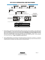
1
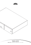
CP-ITV4-S 3-Axis ITV Control Panel Telemetrics Control Panel for the Sony EVI-D30, EVI-D70, EVI-D100, EVI-HD3V, BRC-300, BRC-700 and Elmo PTC-100 Pan/Tilt Video Cameras enhances function and value for Teleconferencing, Educational, and Security Applications. P/N 92 55418 102 – 11 REV FIRMWARE VERSION 55502 004 REV- Page 6 Leighton Place Mahwah, New Jersey 07430 P: 201•848•9818 F: 201•848•9819 1 CP-ITV4-S OPERATING INSTRUCTIONS System with Daisy Chain Wiring Interconn ect Cable 15’ CA-ITV-S15 25’ CA-ITV-S25 50’ CA-ITV-S50 Control Cable 6’ CA-ITV-DIN-6 25’ CA-ITV-DIN-25 Interconnect Cable 15’ CA-ITV-S15 25’ CA-ITV-S25 50’ CA-ITV-S50 Interconnect Cable 15’ CA-ITV-S15 25’ CA-ITV-S25 50’ CA-ITV-S50 *Extension Cable (Optional) 25’ CA-ITV-D-25 300’ CA-ITV-D-300 50’ CA-ITV-D-50 400’ CA-ITV-D-400 100’ CA-ITV-D-100 500’ CA-ITV-D-500 200’ CA-ITV-D-200 Cables > 500’ use Rs422 kit Remote Panel * Remote Panel o nly available with da isy chain configuratio n Remote Control Cable 25’ CA-ITV-P25 PORT 4 CP-ITV4-S P ORT 1 PORT 3 Video Switcher Comprehensive CVG-SW61CS Control Cable 10’ CA-ITV-V10 PORT 4 CP-ITV4S * For Plenum cab les, use part number CA-ITV-DP-XXX (where XXX=feet). PORT 1 2 3 4 DESCRIPTION SONY EVI-D100 CAMERA NOT USED VIDEO SWITCHER (CVG-SW61CS) REMOTE PORT Connect power, camera data, and video switcher cables to rear panel. The port marked 1 is the output for the EVI-D100 CAMERAS 1-4. Daisy chain the EVI-D100 cameras from camera 1 through camera 4 using the data in and out connectors on the EVI-D100’s using cables included. IMPORTANT: Do not barrel DB9 to 8 pin miniDIN to 8 pin mini-DIN to DB9 to make 8 pin mini DIN to 8 pin mini DIN cable. The port marked 2 is for the document camera (NOT USED). The port marked 3 is the output for the VIDEO SWITCHER. The port marked 4 is for remote serial control. TURN THE CONTROL PANEL ON LAST. Select CAMERA/VIDEO to be controlled by momentarily pressing the proper button (1 through 4). If a camera is not present, the LED will blink for 4 seconds. To select another camera press any of the other camera selects. If a VIDEO SWITCH is connected, video output will be on the selected camera. Page 6 Leighton Place Mahwah, New Jersey 07430 P: 201•848•9818 F: 201•848•9819 2 Operate PAN-TILT-ZOOM-FOCUS controls to obtain image desired. To operate focus, use the FR to focus a far object and the NR to focus a near object. If focus control is activated, the focus function will automatically switch from auto to manual to allow for manual focus control, the focus LED will turn off. To return to auto focus, depress the FOCUS AUTO/MAN button. To operate zoom rotate the joystick knob. Turn counterclockwise for wide view and clockwise for telephoto view. To operate the PAN and TILT movement, use the joystick. Up and down is the TILT axis and left and right is the PAN axis. PAN_TILT_ZOOM Joy Stick Response Setting. There are two modes of operation; AUTO SPEED and SPEED SELECTION (default). The AUTO SPEED function will automatically vary the speed of pan/tilt joystick based on the current zoom position, with tighter zooms the joystick speeds will be slower allowing for more precise control. The SPEED SELECTION function setting has 8 steps of joy stick response magnitude to affect pan and tilt speeds. To display the Joy Stick Response Setting; simultaneously press the SPEED Fast (FT) or Slow (SW) buttons momentarily, upon release of the buttons observe the camera and preset LEDs. The LEDs will flash once displaying a code. In AUTO SPEED mode all the LEDs will flash, while in SPEED SELECTION mode only the one LED will flash, the eight LED positions correspond to the eight speeds (CAM1) is slowest speed and (PRESET 4) is fastest speed. To change the Joy Stick Response Setting operation; simultaneously press the SPEED Fast (FT) and Slow (SW) buttons and hold until you see the camera and preset LEDs flash (approximately 3 seconds); this places the unit in AUTO SPEED mode. When in AUTO SPEED mode, when selecting a camera or discontinuing the use of the joystick zoom control the AUTO SPEED value will flash on its indicated LED. By pressing either the SPEED Fast (FT) button or SPEED Slow (SW) button will automatically switch to SPEED SELECTION mode and display the current value. Each time you press a button: SPEED Fast (FT) the speed will increment or SPEED Slow (SW) the speed will decrement. While in SPEED SELECTION mode of operation: to set the SPEED SELECTION press the SPEED Fast (FT) and Slow (SW) buttons while viewing the camera and preset LEDs, the eight speeds correspond to the eight LED positions. Move the joystick to test the new response. Values are stored in permanent memory. To ENTER PRESET, position camera to desired video image and depress selected preset shot switch or switches (1-6) for approximately 2-3 seconds. When the LED for that preset becomes lit the shot is memorized. To RECALL PRESET shot, depress preset switch or switches (1-6) for about a half a second. Some manufacturer’s cameras preset shots will remain in memory when power is shut off. Pan, tilt, zoom, focus, and focus mode (auto/manual) are memorized. NOTE: to enter or recall preset shot number 5 use preset buttons 1 and 2 simultaneously; for number 6 use preset buttons 3 and 4 simultaneously. Depress the EXPOSURE switches to adjust the iris. This function is not presetable and is manually adjusted when required for each camera connected. To return to auto-exposure mode, depress both bright and dark buttons simultaneously. Page 6 Leighton Place Mahwah, New Jersey 07430 P: 201•848•9818 F: 201•848•9819 3 The LOC/REM allows for control of a remote camera system. The local/remote function can only be used in systems using the daisy chain connection. This feature allows a remote serial device connected to port 4 of the ITV control panel to gain control of the cameras connected to the ITV panel. The remote device can be another CP-ITV control panel, computer, or other control source (AMX, Crestron, etc.) When the LOC/REM button on the remote panel is pressed, the LED will turn green indicating that you have remote control of the cameras connected to the local panel. The LOC/REM button on the local panel will be flashing indicating that a remote device has control of the local cameras. The local panel can regain control of the cameras by pressing the LOC/REM button. The button will go out on both panels, indicating that the local panel has control of the local cameras, and the remote panel does not. If both control panels have cameras attached to the panel, either panel can remotely control cameras. It is not possible to remotely control each others cameras simultaneously. NOTE: Gaining control of remote cameras may not happen on the first key press. The local panel will only give up control when no operation or communication is taking place. Another key press may be required until control is taken. System with Hom e Ru n Wir ing Control Cabl e 6’ CA-ITV-DIN-6 25’ CA-ITV-DIN-25 PO RT 1 POR T 2 PORT 3 P ORT 4 *Extension Cable (O ptional) 25’ CA-ITV-D-25 50’ CA-ITV-D-50 100’ CA-ITV-D-100 200’ CA-ITV-D-200 300’ CA-ITV-D-300 400’ CA-ITV-D-400 500’ CA-ITV-D-500 * Remote Panel o nly available with da isy chain configuratio n CP-ITV4-S * For Plenum cab les, use part number CA-ITV-DP-XXX (where XXX=feet). Connect power, camera data cables to rear panel. The port marked 1 is the output for the EVI-D100 CAMERA 1. The port marked 2 is the output for the EVI-D100 CAMERA 2. The port marked 3 is the output for the EVI-D100 CAMERA 3. The port marked 4 is the output for the EVI-D100 CAMERA 4. TURN THE CONTROL PANEL ON LAST. Select CAMERA to be controlled by momentarily pressing the proper button (1 through 4). If a camera is not present, the LED will blink for 4 seconds. To select another camera press any of the other camera selects. Operate PAN-TILT-ZOOM-FOCUS controls to obtain image desired. To operate focus, use the FR to focus a far object and the NR to focus a near object. If focus control is activated, the focus function will automatically switch from auto to manual to allow for manual focus control. To return to auto focus, depress the FOCUS AUTO/MAN button. To operate zoom rotate the joystick knob. Turn counterclockwise for wide view and clockwise for telephoto view. To operate the PAN and TILT movement, use the joystick. Up and down is the TILT axis; and left and right is the PAN axis. Page 6 Leighton Place Mahwah, New Jersey 07430 P: 201•848•9818 F: 201•848•9819 4 To ENTER PRESET, position camera to desired video image and depress selected preset shot switch or switches (1-6) for approximately 2-3 seconds. When the LED for that preset becomes lit the shot is memorized. To RECALL PRESET shot, depress preset switch or switches (1-6) for about a half a second. Some manufacturer’s cameras preset shots will remain in memory when power is shut off. Pan, tilt, zoom, focus, and focus mode (auto/manual) are memorized. NOTE: to enter or recall preset shot number 5 use preset buttons 1 and 2; for number 6 use preset buttons 3 and 4. PORT 1 2 3 4 DESCRIPTION SONY EVI-D100 CAMERA 1 SONY EVI-D100 CAMERA 2 SONY EVI-D100 CAMERA 3 SONY EVI-D100 CAMERA 4 Toggle between DAISY CHAIN and HOME RUN modes: Simultaneously press preset buttons 1,2,3 & 4 (not camera select buttons) at any time, and hold them down until they light. Camera button 1 or 2 will blink indicating present connection mode. Camera button 1 indicates DAISY CHAIN mode. Camera button 2 indicates HOME RUN mode. Press Camera button 1 or 2 to change or confirm desired mode. Button will light for about 1 second then all LEDs will turn off. Note: when selecting HOME RUN mode the camera LEDs will flash in sequence momentarily. Unit is now ready to operate. Page 6 Leighton Place Mahwah, New Jersey 07430 P: 201•848•9818 F: 201•848•9819 5 Connector Pinouts: C A M 1 C A M 2 D C PWR AUX C A M 3 C A M 4 Serial Port Connector 1 5 9 6 9 D-SUB Male (Connector View) PIN# 1 2 3 4 5 DESCRIPTION N/C Receive Data Transmit Data N/C Ground PIN# 6 7 8 9 DESCRIPTION N/C RTS N/C N/C POWER CONNECTOR 5.1mm x 2.1mm - + 9V 500mA Page 6 Leighton Place Mahwah, New Jersey 07430 P: 201•848•9818 F: 201•848•9819 6 SONY EVI-D100 OWNERS PLEASE READ! To use the Sony EVI-D100 camera with the Telemetrics CP-ITV4-S3-Axis ITV Control Panel, the EVI-D100 must be set to work in EVI-D70 mode. You must place the EVI-D100 into EVI-D30 emulation mode. A switch is located on the bottom of the EVI-D100 to set the emulation mode. Please refer to the EVI-D100 manual. Please make sure that the baud rate for the camera is 9600 baud. SONY EVI-D70 OWNER PLEASE READ! To use the Sony EVI-D70 camera with the Telemetrics CP-ITV4-S 3-Axis ITV Control Panel, the EVI-D70 must be set to work in EVI-D30 mode. You must place the EVI-D70 into EVI-D30 emulation mode. A switch is located on the bottom of the EVI-D70 to set the emulation mode. The baud rate for the camera must be 9600 baud. Please refer to the EVI-D70 manual. Customers using the CP-ITV-D100 (purchased prior to February 2004) with firmware versions 53355 016 REV F and lower may notice a communications lag between the control panel and Sony EVI-D70. The firmware can be identified by removing the bottom cover of the CP-ITV-D100. To get the best performance from your CP-ITV-D100, please contact Telemetrics Inc. for an updated firmware. SONY EVI-D30 OWNERS PLEASE READ! The Telemetrics CP-ITV4-S 3-Axis ITV Control Panel operates the EVI-D30 camera directly. Please make sure that the baud rate for the camera is 9600 baud. ELMO PTC-100 OWNERS PLEASE READ! The Telemetrics CP-ITV4-S 3-Axis ITV Control Panel operates the Elmo PTC-100 camera directly for serial number 101426 and higher. All other PTC-100 please contact Telemetrics Inc. for the correct firmware. The older PTC-100 did not correctly employ variable control of pan and tilt. Please make sure that the baud rate for the camera is 9600 baud. SONY EVI-HD3V OWNERS PLEASE READ! To use the SONY EVI-HD3V with the Telemetrics CP-ITV4-S 3-Axis ITV Control Panel, the SONY EVI-HD3V must be set to 9600 baud (DIP Switch on bottom). Please, refer to camera manual. Page 6 Leighton Place Mahwah, New Jersey 07430 P: 201•848•9818 F: 201•848•9819 7