1
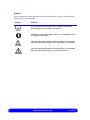
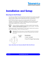
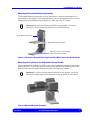
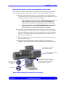
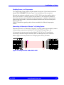
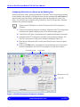
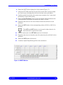
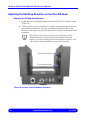
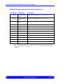
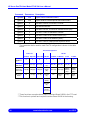
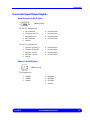
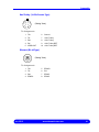
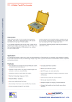
HP Servo Pan/Tilt Head Model PT-HP-S4 User’s Manual rev 05/15 www.telemetricsinc.com Revision History Manual Software Version Firmware Version Description May 2015 XXXX XXXX Initial issue. Copyright Copyright© 2015 Telemetrics Inc. All rights reserved. This material may not be reproduced or copied, in whole or in part, without the written permission of Telemetrics Inc. Technical Support Contact Telemetrics Inc. for technical support: Telemetrics Inc. 6 Leighton Place Mahwah, New Jersey, 07430 Phone: (201) 848-9818 Fax: (201) 848-9819. www.telemetricsinc.com rev 05/15 Preface About this Manual This manual contains installation and operational information for the Telemetrics HP Servo Pan/Tilt Head Model PT-HP-S4. This unit is primarily designed for use with ENG and smaller types of cameras. Many options of the Telemetrics Compact Pan/Tilt Head PT-HP-S4 are manufactured, due to the different types of cameras and lenses the device can interface with. Since not all of the available options are described in this manual, please contact Telemetrics if you would like additional information concerning a particular option. Text Conventions Used in this Manual To convey information readily and consistently, certain text conventions are used throughout this manual. These text conventions are as follows: Text Convention Used for Numbered Lists Numbered procedures that should be implemented in order during an operation: 1. Using a terminal program, set the serial port of the personal computer to 9600, no parity, 8 data bits, 1 stop bit, and no flow control. 2. Connect the serial port of the personal computer to the serial port of the Model PT-HP-S4 Pan/Tilt Head. Bold Type Emphasis of any term or component that is being described: If the payload rotates in a clockwise direction when it is not supported, loosen the payload and slide it to the left until the payload remains in a level horizontal position when unsupported. Italics Designating another section of this manual that should be consulted, or designating the name of a screen: If the direction of pan or tilt is backwards, refer to Reversing a Motor Direction on the Serial Data Board on page 15. rev 05/15 www.telemetricsinc.com i Symbols Certain symbols are used throughout this manual to provide a ready visual reference. These symbols are as follows: Symbol Used for A note that provides background or incidental information concerning the current topic or procedure. Indicates an important situation which if not avoided can result in damage to the system. Indicates a possible hazardous situation which, if not avoided, may result in personal injury and/or in damage to the system. Indicates a possible hazardous situation which, if not avoided, may result in personal injury due to electrical shock. ii www.telemetricsinc.com rev 05/15 Important Safety Information Use the following safety guidelines to help ensure your own personal safety and to help protect your equipment and working environment from potential damage. Important! Use the power switch to provide or remove power for the pan/tilt head and its connected devices. Do not connect or disconnect any 48 VDC power cables to turn connected devices on or off. Danger of explosion if the internal lithium battery is replaced incorrectly. Replace only with the same or equivalent type recommended by the manufacturer. Dispose of used batteries according to the battery manufacturer’s instructions. General Safety When Setting Up the Equipment for Use Place the equipment on a hard, level surface. Never place the equipment in a closed-in wall unit. Leave a minimum of six inches (15.25 cm) clearance on all vented sides of the equipment to permit the airflow required for proper ventilation. Restricting airflow can damage the equipment. Do not stack equipment or place equipment so close together that it is subject to recirculated or preheated air. Keep the equipment away from radiators and heat sources. Ensure that the equipment is used within the specified range of operating temperatures. Keep the equipment away from extremely hot or cold temperatures. Do not push any objects into the air vents or openings of your equipment. Doing so can cause personal injury or fire by shorting out interior components. Ensure that nothing rests on the equipment cables and that the cables are not located where they can be stepped on or tripped over. General Safety When Operating the Equipment: Do not use your equipment in a wet environment, for example, near a shower, sink, or in a wet basement. Do not use AC powered equipment during an electrical storm. rev 05/15 www.telemetricsinc.com iii This page intentionally left blank. iv www.telemetricsinc.com rev 05/15 Table of Contents PREFACE About this Manual ................................................................................................... i Text Conventions Used in this Manual ................................................................... i Symbols ................................................................................................................. ii Important Safety Information ............................................................................................... iii General Safety When Setting Up the Equipment for Use..................................... iii General Safety When Operating the Equipment: ................................................. iii INTRODUCTION...........................................................................................................................1 Specifications .......................................................................................................................3 INSTALLATION AND SETUP ......................................................................................................5 Mounting the Pan/Tilt Head..................................................................................................5 Balancing the Payload..........................................................................................................6 Mounting the Payload Balancing Assembly...........................................................7 Mounting the Payload on the Adjustable Camera Cradle......................................7 Balancing the Payload Horizontally on the Adjustable Camera Cradle .................8 Balancing the Payload Vertically on the Adjustable Camera Cradle .....................9 Measuring and Recording the Position of the Balanced Payload........................10 Figure 8 Measuring the Vertical Position of the Cradle .......................................10 Transferring the Payload to the Model PT-HP-S4 Pan/Tilt Head ........................11 Using a Counterweight and/or a Riser Block .......................................................11 Balancing the Payload Horizontally Using a Round Object................................................12 Establishing Power and Communication to the Pan/Tilt Head ...........................................13 Connecting to an External Power Supply ............................................................13 Connecting the Serial Data Port ..........................................................................13 Configuring the DIP Switch Settings on the Serial Data Board ...........................14 Reversing a Motor Direction on the Serial Data Board........................................15 Connecting the Ethernet Port ..............................................................................15 Configuring the IP Address, Net Mask, and Gateway .........................................16 Providing Power to a Teleprompter .....................................................................17 Connecting a Telemetrics Televator® or Trolley System .....................................17 Configuring Soft Limits for a Device on the Auxiliary Axis ...................................18 Adjusting the End Stop Actuators on the Pan/Tilt Head.....................................................20 Adjusting the Tilt End Stop Actuators ..................................................................20 Adjusting the Pan End Stop Actuators.................................................................21 rev 05/15 www.telemetricsinc.com v Establishing Camera Power and Camera Control ............................................................. 22 Establishing Camera Power................................................................................ 22 Interfacing with Fujinon BMD or Canon KTS Series Teleconferencing Lenses .. 22 Calibrating the Camera Lens ............................................................................................. 23 Calibrating a Camera Lens Using the Telemetrics RCCP-1 Control Panel ........ 23 Calibrating a Camera Lens Using the Serial Port of a Personal Computer ........ 24 Calibrating a Camera Lens Using Telemetrics Pan/Tilt Configuration Software . 24 Troubleshooting Camera Lens Calibration.......................................................... 25 Verifying Proper Operation ................................................................................................ 26 APPENDIX ................................................................................................................................. 27 Serial Data Protocol........................................................................................................... 27 Manual Camera Motion ..................................................................................................... 29 Camera Control Voltages.................................................................................... 29 Preset Position Control ....................................................................................... 30 Preset Storing Commands .................................................................................. 30 Preset Recalling Commands............................................................................... 31 Preset Position Data Reporting........................................................................... 31 Request Commands ........................................................................................... 32 Velocity Commands ............................................................................................ 32 PWM Commands ................................................................................................ 33 Miscellaneous Commands .................................................................................. 33 Preset Commands .............................................................................................. 34 Velocity and Acceleration Settings Commands .................................................. 35 Additional Velocity and Acceleration Settings Commands.................................. 36 Soft Limit Commands.......................................................................................... 37 Miscellaneous Setup Commands........................................................................ 37 Connector Input/Output Signals......................................................................................... 39 Serial Controls (9-Pin D Type) ............................................................................ 39 Power (7-Pin XLR Type) ..................................................................................... 39 Lens (12-Pin Male Type)..................................................................................... 40 Camera ROP (10-Pin Male Type) ....................................................................... 40 Aux/Trolley (10-Pin Female Type) ...................................................................... 41 Ethernet (RJ-45 Type)......................................................................................... 41 Tally (12-Pin Female Type)................................................................................. 42 INDEX......................................................................................................................................... 43 vi www.telemetricsinc.com rev 05/15 Introduction The Telemetrics Pan/Tilt Head Model PT-CP-S4 (Figure 1) is a precision pan/tilt head with smooth variable operating speed that is designed for use with ENG and smaller type cameras. The pan/tilt head is designed to be mounted in an upright position on a shelf, tripod, wall mount or Telemetrics Televator® or in an inverted position on a Telemetrics track system. Heavy duty cross roller bearings and swings motors with isolation mounts provide quiet operation. Manual smooth motion is accomplished using velocity servo controls. The lens connector provides direct connection and interface to lens functions. Lens interface options are also available. Auxiliary Interface ce Ethernet Serial In Lens Power In 48 VDC Camera Power and Control Figure 1 Telemetrics HP Servo Pan/Tilt Head Model PT-HP-S4 rev 05/15 www.telemetricsinc.com 1 HP Servo Pan/Tilt Head Model PT-HP-S4 User’s Manual The Model PT-HP-S4 Pan/Tilt Head can be powered from a Rack Mount Power Supply PS-RM-48V and converts the 48 V to appropriate voltage levels for the head, auxiliary robotics devices, camera, lens, and viewfinder. Interconnection between the control unit and Pan/Tilt Head is through RS-232 (standard) or RS-422 (optional) serial data interface. Optional Ethernet connection is also available. A powerful DC-DC converter at the base of the Pan/Tilt head converts 48V to appropriate voltage levels for the head, auxiliary robotics devices, camera, lens, and viewfinder. The Model PT-HP-S4 Pan/Tilt Head is typically controlled by a Telemetrics Robotic Camera Control Panel. Second party RS-232/422 or Ethernet control systems can also be used to interface with the unit. A total of 255 presets are available. The presets are called using shot convergence technology, allowing for smooth motion like presets. An optional camera control feature is available for certain cameras, and a tally LED indicates when the camera is on the air. Please contact your Telemetrics representative if you would like assistance in configuring the Model PT-HP-S4 Pan/Tilt Head. Pin assignments for input and output signals on each of the connectors on the Model PT-HP-S4 Pan/Tilt Head, the serial data protocol that is followed, and a description of the various commands that are utilized are detailed in the Appendix of this manual. 2 www.telemetricsinc.com rev 05/15 Introduction Specifications Specifications for the Telemetrics Model PT-HP-S4 Pan/Tilt Head are summarized below: Input Voltage 38 to 53 VDC Input Current 6.8 A max Input Power 50 W (pan/tilt head only) Camera Power 40 W (13.5 VDC, 3 A maximum)) Pan Travel ±170° with end stops; ±200° without end stops Tilt Travel ±35° (+35° and -90° PTO-HP-S4-EA) End Stops Resolution* Mechanical: continuous angular adjustable – abrupt stop Electronic: smooth stop Pan Velocity Range 0.01°/sec to 25°/sec (40°/sec with high speed PTO-HP-S4-HS) Tilt Velocity Range 0.01°/sec to 25°/sec (40°/sec with high speed PTO-HP-S4-HS) Operating Modes 32 bit velocity and positional servo control Preset position with multi-axis convergence Stopping Accuracy ±5 arc minimum/0.08° Audible Noise 37 dB(A) maximum, IEC Free Field Mounting Upright or inverted Dynamic Load 35 lbs. (16 kg) maximum load Weight 14 lbs. (6.34 kg) Dimensions 10” H x 11.25” W x 6” D 18” H x 11.25” W x 6” D (extended yoke) 14.25” H x 11.25” W x 6” D (extended arms) * End stops are set to ±170° Pan and ±35° Tilt unless otherwise specified by customer. rev 05/15 www.telemetricsinc.com 3 HP Servo Pan/Tilt Head Model PT-HP-S4 User’s Manual This page intentionally left blank. 4 www.telemetricsinc.com rev 05/15 Installation and Setup Mounting the Pan/Tilt Head The Telemetrics Model PT-HP-S4 Pan/Tilt Head is designed to be mounted in an upright position on either a tripod, a shelf, a Telemetrics wall mount, or Telemetrics Televator®. Unless otherwise specified, the PT-HP-S4 will be set up for upright mounting. The PT-HP-S4 can also be mounted in an inverted position when used with a Telemetrics Track system or other similar configuration, since most cameras can be mounted in an inverted position. Please consult Telemetrics if you have questions concerning the feasibility of an inverted mounting. Some camera/lens combinations may require a special camera mounting bracket to optimally position the camera/lens center of gravity. The factory will advise if such a bracket is required. The base plate of the Telemetrics Model PT-HP-S4 Pan/Tilt Head includes mounting holes to accommodate a variety of mountings (Figure 2). Important! Ensure that screws of correct length are used since excessive screw length may interfere with the bottom of the pan/tilt head and hinder pan motion. Figure 2 Base Plate of the Telemetrics Model PT-HP-S4 Pan/Tilt Head rev 05/15 www.telemetricsinc.com 5 HP Servo Pan/Tilt Head Model PT-HP-S4 User’s Manual If the Model PT-HP-S4 Pan/Tilt Head is to be mounted on a Telemetrics Televator®, follow the instructions provided with the Televator® adapter plate. If the Model PT-HP-S4 Pan/Tilt Head is to be mounted on a pipe flange, use the four 1/2-inch1/4 - 20 flat head socket cap screws that are provided. If the Model PT-HP-S4 Pan/Tilt Head is to be mounted on a wall mounting bracket, follow the instructions provided with the bracket. Balancing the Payload The payload (camera, lens, and other equipment) should be balanced horizontally and also vertically about the center of rotation on the tilt axis of the camera cradle to assure the best performance, longevity, and motor life from the Model PT-HP-S4 Pan/Tilt Head. If this detail is overlooked, there will be increased wear on the worm gear, resulting in increased backlash, reduced motor life, and sub-optimal tilting performance. A Payload Balancing Assembly (Figure 3) is available on loan from Telemetrics for balancing the payload horizontally and vertically. This device makes payload balancing easier since an unbalanced payload cannot freely rotate on the Model PT-HP-S4 Pan/Tilt Head due to its precision worm gear drive. If the Payload balancing Assembly cannot be used, the payload should at least be balanced horizontally by placing it on a small round object such as a dowel or pencil. Please refer to page 12 for additional details. Horizontal imbalance of the payload affects performance, longevity, and motor life more than vertical imbalance. Important! Some camera and lens combinations may require use of a special camera mounting bracket to optimally position the camera, lens, and other equipment. Telemetrics can advise you if such a bracket is necessary. 6 www.telemetricsinc.com rev 05/15 Installation and Setup Mounting the Payload Balancing Assembly The Payload Balancing Assembly must be mounted on a secure surface before it is used, either by using bolts in the threaded holes of the mounting plate (Figure 3) or by clamping the Payload Balancing Assembly to a table top using a C-clamp. Important! Be sure that the Payload Balancing Assembly is mounted securely in order to handle the payload you will be balancing. Eight Mounting Screws Adjustable Camera Cradle Mounting Plate, with Threaded Holes for Mounting Bolts Figure 3 Telemetrics Payload Balancing Assembly (With Camera Cradle Attached) Mounting the Payload on the Adjustable Camera Cradle Use the appropriate hardware to initially secure the unbalanced payload to the camera cradle (Figure 4). Choose the holes or slots on the cradle that will properly secure the payload to the camera cradle and then snug the mounting bolts in place. Important! In order to assure proper balancing of the payload, verify that the camera wedge plate and all accessories are mounted on the camera. Figure 4 Mounted Payload (Example) rev 05/15 www.telemetricsinc.com 7 HP Servo Pan/Tilt Head Model PT-HP-S4 User’s Manual Balancing the Payload Horizontally on the Adjustable Camera Cradle After the payload is mounted on the adjustable camera cradle, you will likely notice that the payload is not horizontally balanced (it does not remain level when it is unsupported) because the horizontal center of gravity of the payload is not aligned with the horizontal center of rotation for the camera cradle (Figure 5). 1. Loosen the payload mounting bolts and slide the payload to either the left or right until it remains in a horizontal (level) position when it is unsupported: If the payload rotates in a clockwise direction when it is not supported, loosen the payload and slide it to the left until the payload remains in a level horizontal position when unsupported. If the payload rotates in a counterclockwise direction when it is not supported, loosen the payload and slide it to the right until the payload remains in a level horizontal position when unsupported. If there is insufficient sliding range or rotational clearance, a counterweight may be required (see page 11). 2. When the payload is horizontally balanced, tighten the payload mounting bolts and balance the payload vertically as outlined in the following section. Horizontal Center of Rotation of the Camera Cradle Reposition the Payload so that its Horizontal Center of Gravity is Aligned with the Horizontal Center of Rotation of the Camera Cradle Horizontal Center of Gravity of the Payload Figure 5 Mounted Payload, Positioned Too Far to the Left (Example) 8 www.telemetricsinc.com rev 05/15 Installation and Setup Balancing the Payload Vertically on the Adjustable Camera Cradle After the payload is horizontally balanced, the vertical center of gravity of the payload must be aligned with the vertical center of rotation for the camera cradle (Figure 6). 1. Rotate the payload clockwise until it is nearly upside-down (approximately 170 degrees from its horizontal operating position) and then determine which direction the payload rotates when it is unsupported: If the unsupported payload rotates in a clockwise direction when it is nearly upside-down, move the camera cradle base towards the vertical center of rotation until the payload remains in any position. If the payload rotates in a counterclockwise direction when it is not supported, move the camera cradle base away from the vertical center of rotation until the payload remains in any position. 2. To raise or lower the camera cradle, use a 7/64-inch hex key to loosen the three locking screws on each side of the cradle and then use a 1/4-inch hex driver or ratchet socket wrench on the jack screw to raise or lower the cradle (Figure 6). Clockwise rotation lowers the payload while counter-clockwise rotation raises the payload. 3. When the payload is vertically balanced, tighten the three locking screws on each side of the cradle. 4. Repeat the horizontal balance procedure (page 8) to compensate for changes in the horizontal center of gravity caused during vertical balancing. Vertical Center of Rotation of the Camera Cradle Vertical Center of Gravity of the Payload Locking Screws (Three on Each Side) Reposition the Camera Cradle so that the Vertical Center of Gravity of the Payload is Aligned with its Vertical Center of Rotation Jack Screw Figure 6 Mounted Payload, Positioned Too Low (Example) rev 05/15 www.telemetricsinc.com 9 HP Servo Pan/Tilt Head Model PT-HP-S4 User’s Manual Measuring and Recording the Position of the Balanced Payload After the payload is balanced, the positioning of the payload must be measured before transferring the payload (and cradle, if the Model PT-HP-S4 Pan/Tilt Head adjustable camera cradle was used for balancing) to the same position on the Model PT-HP-S4 Pan/Tilt Head. Save these measurements for future reference. 1. Measure and record the horizontal distance between the edge of the payload and the edge of the cradle (Figure 7) or other convenient reference points. 2. Measure and record the vertical distance between the base of the cradle and the top of the cradle assembly (Figure 8) or other convenient reference points. Horizontal Distance Figure 7 Measuring the Horizontal Position of the Payload on the Cradle Vertical Distance Figure 8 Measuring the Vertical Position of the Cradle 10 www.telemetricsinc.com rev 05/15 Installation and Setup Transferring the Payload to the Model PT-HP-S4 Pan/Tilt Head 1. If the Model PT-HP-S4 Pan/Tilt Head adjustable camera cradle was used for balancing, remove the cradle with the mounted payload from the Payload Balancing Assembly and mount it on the Model PT-HP-S4 Pan/Tilt Head. Otherwise, remove the payload from the Payload Balancing Assembly cradle and mount it on the cradle of the Model PT-HP-S4 Pan/Tilt Head. 2. If needed, adjust the payload horizontally on the cradle to coincide with the position of the payload after horizontal balancing, using the horizontal distance that was measured (Figure 7). 3. If needed, adjust the cradle vertically to coincide with the position of the cradle after vertical balancing, using the vertical distance that was measured (Figure 8). Using a Counterweight and/or a Riser Block If the Payload has a low center of gravity or if there is not enough sliding range or rotational clearance, cradle adjustment and/or positioning of the payload on the cradle may not be sufficient to allow proper balancing. In this case, a riser block and/or counterweight may be required (Figure 9). If a counterweight is used, add just enough weight to oppose the rotating tendency. Please contact your Telemetrics representative if you need additional information or need to obtain a riser block and/or counterweight. Riser Block Counterweight Figure 9 Use of a Riser Block or Counterweight rev 05/15 www.telemetricsinc.com 11 HP Servo Pan/Tilt Head Model PT-HP-S4 User’s Manual Balancing the Payload Horizontally Using a Round Object If the Payload Balancing Assembly cannot be used, the horizontal center of gravity of the payload should at least be determined by placing the payload on a small round object such as a dowel or pen and then rolling it back and forth to determine the horizontal center of gravity of the payload. 1. Mount all of the accessories (such as the lens and camera brackets) on the camera. 2. Place the camera with its mounted accessories on a small round object such as a dowel or pen (Figure 10). 3. Roll the camera with its mounted accessories back and forth to determine the point where balance is achieved. 4. On the camera mount (or other convenient location), mark the position of the dowel or pen where horizontal balance is achieved. 5. Mount the camera with its accessories on the Model PT-HP-S4 Pan/Tilt Head, aligning the mark you made in the previous step with the center of the camera mounting plate on the pan/tilt head. If the payload still has a tendency to rotate forward or backward during operation, loosen the payload mounting fasteners and slide the payload backwards or forwards until the payload maintains an unassisted horizontal and level position, then secure the mounting fasteners. If there is not enough sliding range or rotational clearance, a counter weight may be required. If a counter weight is required, add just enough weight to oppose the rotating tendency. Dowel or Pen Figure 10 Determining the Horizontal Center of Gravity of the Payload 12 www.telemetricsinc.com rev 05/15 Installation and Setup Establishing Power and Communication to the Pan/Tilt Head The notation “XXX” in cable part numbers refers to the length of the cable in feet. Connecting to an External Power Supply Power to the Model PT-HP-S4 is made with interconnect cable CA-PWR-7XLR-XXX (Figure 11) to the 7-pin XLR power connector that is located on the rear of the unit. The other end of interconnect cable connects to the external power supply. Figure 11 Power Cable CA-PWR-7XLR-XXX Connecting the Serial Data Port Communication with a control panel is made with serial data cable CA-RS-XXX (Figure 12) to the 9-pin serial data connector that is located on the rear of the pan/tilt head. The other end of the serial data cable connects to the control panel. Maximum allowable distance between the pan/tilt head and the control panel is 100 feet for pan/tilt heads manufactured to accept RS-232 and 4000 feet for pan/tilt heads manufactured to accept RS-242. Refer to the Appendix for details concerning the serial data protocol. Figure 12 Serial Data Cable CA-RS-XXX rev 05/15 www.telemetricsinc.com 13 HP Servo Pan/Tilt Head Model PT-HP-S4 User’s Manual Configuring the DIP Switch Settings on the Serial Data Board Location of two serial data DIP switches on the Serial Data Board (Part No. 53915) is shown in Figure 13. DIP switch S1 sets the direction of motors for the pan, tilt, track, zoom, focus, iris, and auxiliary axes. Use of each pin on DIP switch S1 is listed below: Pin Description Off On 1 Pan Direction Upright Inverted 2 Tilt Direction Upright Inverted 3 Track Direction Normal Reverse 4 Zoom Direction Lens Specific Lens Specific 5 Focus Direction Lens Specific Lens Specific 6 Iris Direction Lens Specific Lens Specific 7 Auxiliary Direction Normal Reverse 8 Reserved --- --- DIP Switches S1 S2 Figure 13 Serial Data Board (Part No. 53915) 14 www.telemetricsinc.com rev 05/15 Installation and Setup DIP switch S2 sets the Serial Data Board for use with S-232 or RS-422 standards. Use of each pin on DIP switch S2 is listed below: Pin Description Off On 1 RS-232/RS-422 RS-232 RS-422 2 RS-232/RS-422 RS-232 RS-422 Reversing a Motor Direction on the Serial Data Board Motor directions can be reversed. For example, if a pan/tilt head is mounted in an inverted position, it must be set up for inverted mounting or it will drive in the opposite direction (“Up” will be down and “Left” will be right with respect to the drive input). If the factory was notified of the mounting orientation, the drive phase will be correct as shipped. 1. Remove the screws from the tilt drive cover on the side of the unit to access the Serial Data Board (Part No. 53915). 2. Set each pin of DIP switch S1 according to the table on page 14. 3. Carefully close the unit, ensuring that the wires do not bind inside the unit. Connecting the Ethernet Port Communication with a control panel can also be accomplished using an RJ45 Ethernet connector (Figure 14). The unit is 100BASET/10BASET Ethernet compatible. When using the standard LAN CAT5 Cable, the approximate maximum length is 2,000 feet using shielded cable (and less using unshielded cable). Figure 14 Ethernet Cable rev 05/15 www.telemetricsinc.com 15 HP Servo Pan/Tilt Head Model PT-HP-S4 User’s Manual Configuring the IP Address, Net Mask, and Gateway The IP address will be already configured if this information was communicated to Telemetrics when the pan/tilt head was ordered. If needed, the IP address can either be changed or a new IP address can be entered. 1. Connect a personal computer to pan/tilt head by means of an Ethernet cable (see page 1 for the location of the Ethernet connector on the pan/tilt head). 2. Verify that the link light is illuminated on the pan/tilt head Ethernet connector. 3. Launch the DS1 Configuration utility on the personal computer. The Firmware Loader window is displayed (Figure 15). 4. Select the Search button to list devices that are currently installed. 5. Select the device for which the IP Address, Net Mask, and Gateway are to be configured. 6. Select the Change IP button to display a text box for entry of an IP Address. 7. Enter the new IP address, then select OK on the text box. 8. On the Info tab, select the value currently shown for NET MASK. 9. Type the new value for Net Mask, and then press the Enter key. 10. On the Info tab, select the value currently shown for GATEWAY. 11. Type the new value for Gateway, and then press the Enter key. 12. Select the Send Current File button. When entering an IP Address, Net Mask, or Gateway, be sure to enter all leading zeros (for example, enter 010.000.001.103). Figure 15 Firmware Loader Window 16 www.telemetricsinc.com rev 05/15 Installation and Setup Providing Power to a Teleprompter The Teleprompter Power Option provides power through the 12-pin female connector labeled TALLY PROMPT CC1 (see Figure 1 for the location of the connector). Although the maximum available power is 12 VDC, 50 W, use of an auxiliary device such as a Televator® or trolley system with the Model PT-HP-S4 Pan/Tilt Head will reduce the maximum power available for the teleprompter. In addition, the maximum power ratings are based on a maximum distance between the device and the power supply of 100 feet. Consult Telemetrics regarding cables that are available for different teleprompter models. Connecting a Telemetrics Televator® or Trolley System Power and control for a Telemetrics Televator® or trolley system are provided by means of the auxiliary connector on the Model PT-HP-S4 Pan/Tilt Head (Figure 16). It is important to remove power from the Model PT-HP-S4 Pan/Tilt Head before connecting or disconnecting the auxiliary cable, as damage may occur otherwise. Refer to page 18 for the procedure for configuring the auxiliary soft limits. Figure 16 Trolley/Televator Cable CA-S2-AUX rev 05/15 www.telemetricsinc.com 17 HP Servo Pan/Tilt Head Model PT-HP-S4 User’s Manual Configuring Soft Limits for a Device on the Auxiliary Axis A device such as a trolley, elevating pedestal or Televator® that is connected by means of the auxiliary axis interface on the pan/tilt head Can be controlled with soft limits that stop the device smoothly before reaching the mechanical end stop at the limit of its travel. The soft limits are configured using Telemetrics Pan/Tilt Configuration Software installed on a personal computer. Please contact Telemetrics to obtain Telemetrics Pan/Tilt Configuration Software. 1. Connect the personal computer containing Telemetrics Pan/Tilt Configuration Software to the pan/tilt head by means of an Ethernet cable (page 1). 2. Verify that the link light is illuminated on the pan/tilt head Ethernet connector. 3. Launch the Pan/Tilt Configuration software on the personal computer. The Pan/Tilt Convergence Configuration window is displayed (Figure 17). 4. Enter the IP Address and Port for the pan/tilt head in the Connection panel (Figure 17). 5. Select the CONN button. Information for the pan/tilt head and its connected devices is displayed in the Pan/Tilt Convergence Configuration window. Connection Panel Save Panel Miscellaneous Tab Limits Tab Figure 17 Pan/Tilt Convergence Configuration Software 18 www.telemetricsinc.com rev 05/15 Installation and Setup 6. Select the LIMITS tab to display the Limits window (Figure 17). 7. Verify that SET WIN check box for the AUX-X and/or AUX-Y axes is empty (no check mark), indicating that soft limits for these axes are disabled. 8. Carefully position the device at the center (zero) location of its Y-axis travel (elevation) or X-axis travel (track). 9. Select the Pan/Tilt Home button to clear all position registers and save the current position of the device on that axis as “home” or “zero.” 10. Reposition the device to one end of the axis where the soft limit is to be activated. 11. Select the LMT1 button in the corresponding column (AUX-X or AUX-Y) for that axis. The LMT1 and LMT2 buttons can be used in either direction, for back-and-forth or up-and-down travel. 12. Place a check mark in the SET WIN check box for that axis. 13. Reposition the device to the other end of the axis where the soft limit is to be activated. 14. Select the LMT2 button for that axis. 15. If needed, repeat Steps 8 through 14 for the second axis. Figure 18 LIMITS Window rev 05/15 www.telemetricsinc.com 19 HP Servo Pan/Tilt Head Model PT-HP-S4 User’s Manual Adjusting the End Stop Actuators on the Pan/Tilt Head Adjusting the Tilt End Stop Actuators 1. Locate the two tilt end stop actuators on the Model PT-HP-S4 Pan/Tilt Head (Figure 19). 2. Tilt the camera up to its intended limit. If the tilt end stop actuates before the intended limit is achieved, move the upwards tilt end stop actuator in the direction of the upper limit until the camera can be tilted to its intended limit of upward tilt. The tilt end stop actuators are moved by loosening the 4-40 Phillips head lock screw and sliding the actuator around the radius of the stop mounting groove in the direction of the tilt. Use a #1 Phillips head screwdriver to loosen the lock screw. Tilt End Stop Actuator Tilt End Stop Actuator Figure 19 Location of the Tilt End Stop Actuators 20 www.telemetricsinc.com rev 05/15 Installation and Setup 3. When the upward tilt of the camera is at the intended limit, slide the upwards tilt end stop actuator until it is against the limit switch and then lock it in place. Use a #1 Phillips head screwdriver to tighten the lock screw. Do not over tighten the lock screw. It does not have to be tight to hold the tilt end stop actuator in the proper location. Be sure that there is clearance between the stop and the fixed housing assembly after the tilt end stop actuator is locked in place. Tilt end stop actuators must not drag during operation. 4. Tilt the camera down to its intended limit. If the tilt end stop actuates before the intended limit is achieved, move the downward tilt end stop actuator in the direction of the limit until the camera can be tilted to its intended limit of downward tilt. 5. When the downward tilt of the camera is at the intended limit, slide the downward tilt end stop actuator until it is against the limit switch and then lock it in place. 6. Run the camera through its entire tilt range to confirm that both stop locations are correct and that the stops do not bind. Adjusting the Pan End Stop Actuators 1. Locate the pan end stop actuators on the bottom of the Model PT-HP-S4 Pan/Tilt Head. 2. Pan the camera towards the left to its intended limit. If the pan end stop actuates before the intended limit is achieved, move the left pan end stop actuator in the direction of the limit until the camera can be panned towards the left to its intended limit. The pan end stop actuators are moved by loosening the 4-40 Phillips head lock screw and sliding the actuator around the radius of the stop mounting groove in the direction of the pan. Use a #1 Phillips head screwdriver to loosen the lock screw. 3. When the pan of the camera towards the left is at the intended limit, slide the left pan end stop actuator until it is against the limit switch and then lock it in place. Use a #1 Phillips head screwdriver to tighten the lock screw. Do not over tighten the lock screw. It does not have to be tight to hold the pan end stop actuator in the proper location. Be sure that there is clearance between the stop and the fixed housing assembly after the pan end stop actuator is locked in place. Pan end stop actuators must not drag during operation. rev 05/15 www.telemetricsinc.com 21 HP Servo Pan/Tilt Head Model PT-HP-S4 User’s Manual 4. Pan the camera towards the right to its intended limit. If the pan end stop actuates before the intended limit is achieved, move the right pan end stop actuator in the direction of the limit until the camera can be panned towards the right to its intended limit. 5. When the pan of the camera towards the right is at the intended limit, slide the right pan end stop actuator until it is against the limit switch and then lock it in place. 6. Run the camera through its entire pan range to confirm that both stop locations are correct and that the stops do not bind. Establishing Camera Power and Camera Control Telemetrics pan/tilt systems are capable of providing power and data to cameras from virtually all manufacturers. Establishing Camera Power A Telemetrics power supply that includes a 15 V module for the camera must be used when camera power is required. In addition, the Telemetrics control panel must be configured to accept the camera ROP to provide camera control. Interfacing with Fujinon BMD or Canon KTS Series Teleconferencing Lenses In order to use Fujinon BMD or Canon KTS series teleconferencing lenses with the Model PT-HP-S4 Pan/Tilt Head, simply plug the lens control pendant into the connector labeled LENS (see Figure 1 for the location of the connector). Important. If the controller is a Telemetrics preset system, additional modifications must be performed to send the focus and zoom positional voltages from the lens. Please refer to the preset controller manual for complete instructions. If the zoom lens is not a teleconference-style lens with an integral zoom and focus amplifier, an interface cable will be supplied. The connector marked ZOOM plugs into the zoom servo and the connector marked FOCUS plugs into the focus servo. Please refer to the lens and/or camera manual for connections other than remote zoom and focus inputs. Most focus servos require a modification. Please contact your Telemetrics representative for additional information. 22 www.telemetricsinc.com rev 05/15 Installation and Setup Calibrating the Camera Lens The camera lens must be calibrated in order to function properly when using the Model PT-HP-S4 Pan/Tilt Head. The methods are described in the following sections. Important! The camera lens must be configured using Telemetrics Pan/Tilt Configuration Software before it can be calibrated. Refer to the instructions included with the software for lens configuration instructions. When calibrating the camera lens, the pan, tilt, Televator® and track positions are reset to zero and stored presets must be reentered. If you encounter a problem when re-entering stored presets, please contact your Telemetrics representative for assistance. If the camera lens was modified by Telemetrics, it will be delivered already calibrated. If the lens was field-modified or if the lens is being transferred to a Model PT LP S4 Pan/Tilt Head that is currently using a lens from a different manufacturer, lens calibration must be performed. Most focus servos require a modification. Please contact your Telemetrics representative for additional information. Test the lens using the joystick and by entering shots after it is calibrated. Calibrating a Camera Lens Using the Telemetrics RCCP-1 Control Panel 1. Log on to the RCCP-1 Control Panel. 2. Select the camera station for the camera lens that is to be calibrated. The camera station that is currently selected, the model numbers of its Pan/Tilt Head, and the model of its camera are shown on buttons at the bottom of the screen (Figure 20). 3. Select the camera station for the lens that is to be calibrated. The display will update to show information for that camera station on the buttons. 4. Select the button for the Pan/Tilt Head (PT-LP-S4 in the example). The Settings panel is displayed with buttons for homing the pan and tilt mechanism, calibrating the camera lens, and operating the camera devices. 5. Select the Calibrate Lens button on the Settings panel. The lens will first calibrate zoom at a high velocity and then at a low velocity. The calibration will end when focus has reached both limits. 6. Select the button for the Pan/Tilt Head again to cancel display of the Settings panel. Camera Station Pan/Tilt Model Camera Model Figure 20 Buttons Showing the Camera Station, Its Pan/Tilt Head, and Its Camera rev 05/15 www.telemetricsinc.com 23 HP Servo Pan/Tilt Head Model PT-HP-S4 User’s Manual Calibrating a Camera Lens Using the Serial Port of a Personal Computer 1. Using a terminal program, set the serial port of the personal computer to 9600, no parity, 8 data bits, 1 stop bit, and no flow control. 2. Connect the serial port of the personal computer to the serial port of the Model PT-HP-S4 Pan/Tilt Head. The cable connected to the control panel can be disconnected and connected to the personal computer. If a TM-STS Serial Transfer Switch is used, select the camera before disconnecting the cable. DIP switch S2 on the 53915 board is used for setting the pan/tilt head for either RS-232 or RS-422 (page 15). 3. Type a lowercase p, followed by the Enter key. A number should be displayed indicating the pan position and communication. If not, check all settings and connections. 4. Type @ZERO1010 to set the current positions for pan, tilt, and auxiliary axes to zero and calibrate the lens. 5. Wait until the lens has finished its calibration. 6. (If needed) Reconnect the cable to the control panel. Calibrating a Camera Lens Using Telemetrics Pan/Tilt Configuration Software The camera lens can be calibrated (and configured, if needed) using Telemetrics Pan/Tilt Configuration Software installed on a personal computer. If a lens is replaced with the same model of lens, only lens calibration is required. If a lens is replaced with a different model of lens, the lens must be configured. Refer to the instructions included with the software for lens configuration instructions. 1. Connect the personal computer containing Telemetrics Pan/Tilt Configuration Software to the pan/tilt head by means of an Ethernet cable (page 1). 2. Verify that the link light is illuminated on the pan/tilt head Ethernet connector. 3. Launch the Pan/Tilt Configuration utility on the personal computer. The Pan/Tilt Convergence Configuration window is displayed with the Miscellaneous tab selected by default (Figure 17). 4. Enter the IP Address and Port for the pan/tilt head in the Connection panel (Figure 17). 5. Select the CONN button. Information for the pan/tilt head and its connected devices is displayed in the Pan/Tilt Convergence Configuration window. 6. Select the Lens Calibration button to calibrate the lens and to cycle the zoom and focus. This operation can take several minutes. 24 www.telemetricsinc.com rev 05/15 Installation and Setup Troubleshooting Camera Lens Calibration Problem Action Lens reverses direction while moving zoom to tele or wide. Perform the lens calibration. If the problem still exists, use the Telemetrics Pan/Tilt Configuration Software to reset the lens parameters and then calibrate. If the problem still exists, using the Telemetrics Pan/Tilt Configuration Software lower the zoom (Manual, Preset – Fade, Preset – Cut) maximum velocity until the problem is resolved. Focus cannot reach extreme limits. Perform the lens calibration. Lens does not calibrate. Check the lens modification to ensure zoom and focus potentiometers are available to the pan/tilt. The Telemetrics Pan/Tilt Configuration Software may be used to verify potentiometers response since it continually polls for zoom and focus position. Zoom and Focus operate manually, but only presets operate on focus. Check the lens modification to ensure zoom and focus potentiometers are available to the pan/tilt. The Telemetrics Pan/Tilt Configuration Software may be used to verify potentiometers response since it continually polls for zoom and focus position. If the problem still exists, use the Telemetrics Pan/Tilt Configuration Software to reset the lens parameters and then calibrate. Perform the lens calibration. If the problem still exists, use the Telemetrics Pan/Tilt Configuration Software to reset the lens parameters and then calibrate. No control of lens functions. Perform the lens calibration. If the problem still exists, use the Telemetrics Pan/Tilt Configuration Software to reset the lens parameters and then calibrate. Check the lens modification to ensure zoom and focus potentiometers are available to the pan/tilt. The Telemetrics Pan/Tilt Configuration Software may be used to verify potentiometers response since it continually polls for zoom and focus position. rev 05/15 www.telemetricsinc.com 25 HP Servo Pan/Tilt Head Model PT-HP-S4 User’s Manual Verifying Proper Operation After the camera has been mounted on the Model PT-HP-S4 Pan/Tilt Head, all connections have made, and installation is completed, operation of the system should be tested. 1. (If needed) Power up the Model PT-HP-S4 Pan/Tilt Head and camera. 2. Move the pan joystick left. The camera should move to the left of the scene as viewed on a picture monitor. 3. Move the pan joystick right. The camera should move right. The amount of angular deflection on the joystick determines the velocity of the Pan/Tilt. Releasing the joystick will stop movement. 4. Move the tilt joystick down (toward the operator). The camera should move down on the scene. 5. Push the tilt joystick up (away from the operator). The camera should move up on the scene. Again, angular deflection determines velocity. 6. Move the zoom joystick up (away from the operator) or turn the zoom knob clockwise. The lens should zoom to telephoto. 7. Move the zoom joystick down (toward the operator) or turn the zoom knob counterclockwise. The lens should zoom to wide. 8. Move the focus joystick side to side. The focal length of the lens should change (Left =Infinity, Right = Near). Again, angular deflection determines the velocity of zoom and focus. 9. If a motor direction must be reversed, refer to Reversing a Motor Direction on the Serial Data Board on page 15. 26 www.telemetricsinc.com rev 05/15 Appendix Serial Data Protocol Telemetrics provides for serial control of many of its camera control products. In this section, which describes the protocol that is used for serial control of these devices, the Telemetrics controlled device is referred to as the "controller" and the device commanding the head is referred to as the "host". Important! The communication rate is 9600 BAUD. Protocol is 8 data bits, one stop bit, and no parity. Control is accomplished by sending commands consisting of ASCII characters terminated by an ASCII carriage return (<CR>, hex 0D). In most cases, several commands may be sent together on the same line before sending the <CR>. However, in the case of the recall preset command, other commands may precede it but any control commands following it on the same line are ignored. Feedback commands will still continue to respond. A control command line will not be executed until the <CR> is received. ASCII backspace (<BS>, hex 08) can be used to correct errors in the command line. After the command line has been executed, a <CR> will be sent back to the host to acknowledge completion. Each command consists of letters and may be followed by numerical parameters needed for the command. The commands are CASE SENSITIVE. Numerical parameters are specified by the string of ASCII digits representing the decimal value. For example, a value of 26 is sent as a '2' followed by a '6', (i.e., hex 32, hex 36). Where a command has more than one parameter, the parameters should be separated by a space. No other spaces are necessary, though they may be used if desired. In cases where the host does not monitor responding carriage returns from the controller, the host will not know whether a command line has been completed. The controller can receive new commands while it is processing previous commands except when the controller is processing a preset position recall. During a preset recall, all incoming characters are ignored except for an ASCII cancel character (<CAN>, control-X, hex 18) which tells the controller to abort the recall. Therefore, the host should send a <CAN> preceding all command lines. This way, if a recall was in progress, it will be aborted and the controller will accept the command. If no recall was in progress, the <CAN> will be ignored. rev 05/15 www.telemetricsinc.com 27 HP Servo Pan/Tilt Head Model PT-HP-S4 User’s Manual The remainder of this section describes the general methods for serial camera control. Commands will be introduced as they are needed. Note that while examples are shown enclosed in single quotes, only the characters within the quotes are to be sent; the quotes are simply for clarity. In addition, the examples may use unnecessary spaces for clarity, which need not be used for the actual application. 28 www.telemetricsinc.com rev 05/15 Appendix Manual Camera Motion The procedure for manually moving a camera is to: 1. Reset motion voltages with the 'R' command. 2. Move the camera using 'P', 'T' "Z' and 'F' commands. The commands that are used are detailed in the following two sections. Camera Control Voltages Camera motion is controlled by four voltages corresponding to the velocity of pan, tilt, zoom and focus, which are set using the 'P', 'T', 'Z' and 'F’ commands respectively. 'X' and 'Y' commands are also available to control the trolley and dolley, if used. Iris control may also be available, depending on the control panel options and lenses. The commands have a single numerical parameter determining the voltage to which the output is set. The value of the parameter is in the range of 0 to 32767. A parameter value of 16383 is the point at which no motion occurs. As the value moves away from 16383, the speed of motion increases, and the direction of motion is determined by whether the value is greater or less than 16383 as follows: Command < Less than 16383 > Greater than 16383 ‘P’ Pan Right Left ‘T’ Tilt Down Up ‘Z’ Zoom In (Tele) Out (Wide) ‘F’ Focus Near Far ‘X’ Televator/Trolley Down/Right Up/Left ‘Y’ Dolley Right Left “I” Iris Close Open In addition, the 'R' command, which has no parameters, will reset all control voltages to the no motion value. There are many methods for determining control voltages. For instance, a joystick can be used and the value it outputs converted to the range 0 to 32767 for control voltages. Use of buttons for camera control, where each function has two buttons for direction of motion (i.e. pan left and pan right), provides another example. When a button is selected, the camera is enabled with the initial control voltage for the function set for slow movement. Then, the longer the button is held down, the faster the camera moves. If there is limited processing ability, button control can be done with a simple on/off type control where pressing a button moves the corresponding function at a fixed speed. rev 05/15 www.telemetricsinc.com 29 HP Servo Pan/Tilt Head Model PT-HP-S4 User’s Manual Preset Position Control There are 256 preset positions (numbered 0 to 255) that are available in the non-volatile memory of the controller. The information stored in a preset location does not include the camera to which the preset corresponds, and it is therefore up to the host application to select the proper camera to be used prior to preset operations. The normal method for preset control is to: 1. Read and store preset position with the 'E' command. 2. Recall position using the 'C' command. Alternately, the host can store presets in its own memory by reading the position of the camera and using a variant of the recall command to recall the position: 1. Read position using commands. 2. Store data reported by controller. 3. Recall position using 'CX' command with stored data. There are two additional commands related to presets: The 'e' command (whose parameter is a preset number) which reports to the host the position data stored in the preset number in order of pan, tilt, zoom, and focus. The 'EX' command stores external data in the controller's preset storage and is a variant of the enter command. The first parameter is the preset number in which to store the data, and that is followed by the position data to be stored. Detailed descriptions of preset related commands are provided in the following three sections. Preset Storing Commands The 'E' command stores the position of the currently selected camera. Its single parameter is the preset number into which to store the position. For example, to store the current position into preset number 23: 'E 23 <CR>' The 'EX' variant of the enter preset command allows host supplied data to be stored into a preset. The first parameter of this command is the preset number into which to store the data. This parameter is followed by position data corresponding to be stored into the preset. These data range varies from parameter to parameter. An example of this command is as follows: 'EX 5 123 456 789 123 456 789 123 456 <CR>' The command in the example stores a pan position of 123, tilt position of 456, zoom position of 789, focus position of 123, trolley position of 456, iris position of 789, master pedestal position of 123 and dolley position of 456 into preset number 5. 30 www.telemetricsinc.com rev 05/15 Appendix Preset Recalling Commands The ‘C’ command recalls the preset position stored in the preset number given as its parameter. As noted earlier in this document, once the controller begins a recall command, any control commands remaining on the command line are ignored. While the recall is in progress, the only character that will be acted upon is the <CAN> character to abort the shot. If the controller receives a <CAN> while in the midst of a recall, the camera will stop where it is and processing will continue as though the camera had actually reached the shot. After the recall is complete, the controller responds with a <CR>. For example to recall the position stored in preset number 41: ‘C 41 <CR>‘ The ‘CX’ variant of the recall command allows position data to be supplied directly by the host. ‘CX 123 456 789 123 456 789 123 456 789 <CR>‘ Preset Position Data Reporting The ‘e’ command, whose parameter is a preset number, sends back to the host the four position data stored in that preset number, in order of pan, tilt, zoom and focus. These data are in the range for position data described earlier. For example, after externally entering the data in the example shown in the preceding Preset Storing Commands section: Host sends: ‘e 5 <CR>‘ Controller responds: ‘123 456 789 123 456 789 123 456 <CR>‘ The ‘p’, ‘t’, ‘z’ and ‘f’ commands, having no parameters, read the current position of the pan, tilt, zoom and focus. For example: Host sends: ‘p t z f <CR>‘ Controller responds: ‘111 222 333 444 <CR>‘ rev 05/15 www.telemetricsinc.com 31 HP Servo Pan/Tilt Head Model PT-HP-S4 User’s Manual Request Commands Command Parameters Description p ± 2147483647 (± 231) Current Pan Position t ± 2147483647 (± 231) Current Tilt Position z 0 – 1024 (210) Current Zoom Position f 0 – 1024 (210) Current Focus Position x ± 2147483647 (± 231) Current Trolley/Pedestal Position y ± 2147483647 (± 231) Current Aux Position i 0 – 255 (210) Current Iris Position m 0 – 255 (210) Current Master Pedestal Position s “MASTER = XX LENS = YY” Returns the number of times the Microprocessors have COP reset O B[x] x = 0,1 (TALLY) Returns Command Character of WP function and 0 for off, 1 for On G[x] x = 0,1 (EXT) V[x] x = 0,1 (CAM PWR) W[x] x = 0,1 (WIPER) U[x] x = 0,1 (WASHER) K[x] x = 0,1 (CONT.CLOS) im “IA” = AUTO “ILP” = LOCAL Return Iris Mode Velocity Commands Command 32 Parameters Description P 0 – 32767 (215) Set Pan Velocity ( 0 = R ; 16383 = STOP ; 32767 = L) T 0 – 32767 (215) Set Tilt Velocity ( 0 = D ; 16383 = STOP ; 32767 = U) Z 0 – 32767 (215) Set Zoom Velocity ( 0 = T ; 16383 = STOP ; 32767 = W) F 0 – 32767 (215) Set Focus Velocity ( 0 = N ; 16383 = STOP ; 32767 = F) X 0 – 32767 (215) Set (Aux) Trk/Ped Velocity ( 0 = R,D; 16383 = STOP ; 32767 = L,U) Y 0 – 32767 (215) Set Aux Velocity ( 0 = R ; 16383 = STOP ; 32767 = L) I 0 – 32767 (215) Set Iris Velocity ( 0 = C ; 16383 = STOP ; 32767 = O) R <NONE> Stop All Motion www.telemetricsinc.com rev 05/15 Appendix PWM Commands Command Parameters Description p ± 255 (± 28) Set Pan PWM Drive (-255 = R ; 0 = STOP ; 255 = L) t ± 255 (± 28) Set Tilt PWM Drive (-255 = D ; 0 = STOP ; 255 = U) z ± 255 (± 28) Set Zoom PWM Drive (-255 = T ; 0 = STOP ; 255 = W) f ± 255 (± 28) Set Focus PWM Drive (-255 = N ; 0 = STOP ; 255 = F) x ± 255 (± 28) Set Trk/Ped PWM Drive (-255 = R ; 0 = STOP ; 255 = L) y ± 255 (± 28) Set Aux PWM Drive (-255 = R ; 0 = STOP ; 255 = L) Miscellaneous Commands Command rev 05/15 Parameters Description B <NONE> Turn Tally On b <NONE> Turn Tally Off G Turn Extender On g Turn Extender Off W Turn Wiper On w Turn Wiper Off U Turn Washer On u Turn Washer Off V Turn Cam Power On (Stabilizer) v Turn Cam Power Off (Stabilizer) K Turn Contact Closure On k Turn Contact Closure Off (Only Works for On-Board TM Contact Closure) A <NONE> Resets the number of times the Microprocessors have COP reset IA <NONE> Sets Iris to Auto Mode (Camera takes control) IL <NONE> Sets Iris to Local Mode (P/T takes control) II ± 255 Increments Current Iris Position (+ = Close , - = Open) BI ± 255 Increments Current Master Pedestal (Black) Position FI ± 255 Increments Current Focus Position www.telemetricsinc.com 33 HP Servo Pan/Tilt Head Model PT-HP-S4 User’s Manual Preset Commands Command Parameters Description C 0 – 255 Call Preset Shot E 0 – 255 Enter Preset Shot e 0 – 255 Show Position Parameters for Shot 0x18 <NONE> Cancel Current Shot (press CTRL+X or send a hexadecimal 18) CX* SPECIAL Call Preset Shot using supplied parameters EX SPECIAL Store Preset Shot using supplied parameters (Not Available) CV** SPECIAL Progressive Positional Motion (Special Option) * An example of the “CX” command is the following, where FADE is the fade time in milliseconds: ‘CX <Ppos> <Tpos> <Zpos> <Fpos> <Xpos> <OPTIONAL Iris pos> <OPTIONAL PED pos> <OPTIONAL Ypos> <FADE>’ ** The “CV” command is used to move an axis in positional mode and is usually used in instances where continuous position adjustment is required. A new position for a move should be updated at least every 40 milliseconds and position updates should not exceed a total of two seconds, since a move timeout (the controller will respond “TimedOut”) occurs two seconds after the last positional command is received. To omit an axis from positional mode, fill in its respective position as “0” in the command structure, since the controller will ignore moves to position 0. An example of the “CV” command is the following: ‘CV <P pos> <T pos> <Z pos> <F pos> <0> <0>’ The following example shows how the “CV” command can be used to start a pan move in positional mode: Time 34 Command 0 msec ‘CV 15000 0 0 0 0 0 <CR>’ 40 msec ‘CV 15100 0 0 0 0 0 <CR>’ 80 msec ‘CV 15200 0 0 0 0 0 <CR>’ 120 msec ‘CV 15300 0 0 0 0 0 <CR>’ www.telemetricsinc.com rev 05/15 Appendix Velocity and Acceleration Settings Commands Command* Parameters Description @VEL= See “Description” column Show Axis Velocity Settings (P=1,T=2,X=3,Z=4,F=5,I=6,Y=7) @LVEL See “Description” column Load Axis Default Velocity Settings (P=1,T=2,X=3,Z=4,F=5,I=6,Y=7) @?JVH 0-2147483647 (231) Set Axis Maximum Velocity for Joystick Controls @?JVL 0-2147483647 (231) Set Axis Minimum Velocity for Joystick Controls @?PVH 0-2147483647 (231) Set Axis Maximum Velocity for Preset Fade Shots @?PVL 0-2147483647 (231) Set Axis Minimum Velocity for Preset Fade Shots @?CVH 0-2147483647 (231) Set Axis Maximum Velocity for Preset Cut Shots @?CVL 0-2147483647 (231) Set Axis Minimum Velocity for Preset Cut Shots @ACC= See “Description” column Show Axis Acceleration Settings (P=1,T=2,X=3,Z=4,F=5,Y=7) @LACC See “Description” column Load Axis Default Acceleration Settings (P=1,T=2,X=3,Z=4,F=5,Y=7) @?JAM 0-2147483647 (231) Set Axis Maximum Acceleration for Joystick Controls @?PAM 0-2147483647 (231) Set Axis Maximum Acceleration for Preset Fade Shots @?CAM 0-2147483647 (231) Set Axis Maximum Acceleration for Preset Cut Shots * The “?” character in a command indicates that the numerical code for each axis shown in the “Description” column (i.e.; P, T, X, F, I, Z, or Y) can be entered for that command. rev 05/15 www.telemetricsinc.com 35 HP Servo Pan/Tilt Head Model PT-HP-S4 User’s Manual Additional Velocity and Acceleration Settings Commands Command* Parameters Description @PID= See “Description” column Show Axis PID settings (P=1, T=2, X=3, Y=7) @SET= See “Description” column Burn Axis PID settings (P=1, T=2, X=3, y=7) @LPID See “Description” column Load Axis Default PID settings (P=1, T=2, X=3, y=7) @?KP= 0-32767 Set Axis KP (Proportional Gain) @?KD= 0-32767 Set Axis KD (Derivative Gain) @?KI= 0-32767 Set Axis KI (Integral Gain) @?IL= 0-32767 Set Axis IL (Integration Limit) @?OL= 0-255 Set Axis OL (Output Limit) @?CL= 0-255 Set Axis CL (Current Limit) @?EL= 0-16383 Set Axis EL (Position Error Limit) @?SR= 0-255 Set Axis SR (Servo Rate Divisor) @?DB= 0-255 Set Axis DB (Dead Band Compensation) * The “?” character in a command indicates that the numerical code for each axis shown in the “Description” column (i.e.; P, T, X, or Y) can be entered for that command. 36 www.telemetricsinc.com rev 05/15 Appendix Soft Limit Commands Command Parameters Description @LIMS see “Description” column Show Axis Soft Limit (P=1,T=2,X=3,Z=4,F=5,Y=7) @LIME see “Description” column Enable Soft End Limit (P=1,T=2,X=3,Z=4,F=5,Y=7) @LIMD see “Description” column Disable Soft End Limit (P=1,T=2,X=3,Z=4,F=5,Y=7) @AUTO see “Description” column Automatically Find Physical End Limit (P=1,T=2,X=3,Z=4,F=5,Y=7) @?LIM 1,2 Set Window Soft Limit (Upper = 1, Lower = 2) @?UW= ± 2147483647 (± 231) Set Axis Upper Window @?LW= ± 2147483647 (± 231) Set Axis Lower Window * The “?” character in a command indicates that the numerical code for each axis shown in the “Description” column (i.e.; P, T, X, Z, F or Y) can be entered for that command. Miscellaneous Setup Commands Command rev 05/15 Parameters Description @PROG 1010 Upload New Firmware to Flash @INIT 1010 Initialize Servos @ZERO 1010 Calibrate Lens @CNTR 1010 Reset Positions (Sets Current P/T Head Position to Center) @REFS 1010 Report Digital Pot Settings for Zoom & Focus @ZREF 0-255 Set Digital Pot for Zoom @FREF 0-255 Set Digital Pot for Focus @ZRCF 1010 Reads Zoom Correction Factor @ZGCF 0-16383 Set Zoom Gain Correction Factor @ZOCF 0-16383 Set Zoom Offset Correction Factor @ZTCF 0-16383 Set Zoom Time Correction Factor @VERS 1010 Report Firmware Version @DIPS 1010 Report Current Dip Switch Status www.telemetricsinc.com 37 HP Servo Pan/Tilt Head Model PT-HP-S4 User’s Manual Command Parameters Description @CAMS 1010 Report Camera Initialization Status @WPCT 1010 Report Weather Proof/Peripheral CMD Enable Status @WPCT 0 Use with PT-CP-S2, PT-HP-S2, PT-LP-S2* @WPCT 1 Use with HD-HOU-S2* @WPCT 2 Use with PT-LP-S3, PT-HP-S2 w/ Contact Closure (CC)* @WPCT 3 Use with PT-LWP-S3 Standard w/ Washer* @WPCT 4 Use with PT-LWP-S3 w/ Contact Closure (CC)* @WPCT 5 Use with PT-LWP-S3 w/ Stabilizer (Stab.)* @WPCT 6 Use with PT-HP-S4, swaps pan/tilt requires a reboot * The parameter that is used for each Pan/Tilt configuration is shown in the table below: Pan/Tilt Configuration Indoor S2 WP S3 Standard Optional Indoor S3 WP S2 @WPCT 0 2 2 PT7 (J4) RDY LED READY Ext. (G) Ext. (G) PT6 (J14) Tally (B) TALLY LED Tally (B) Tally (B) Wiper (W) CC (K) CC (K) Washer (U) PP7 (J13) GPIO n/a Standard w/ Washer 1 3 Cam. Pwr. Ext. (G) (V) w/ CC w/ Stab. 3 4 5 Ext. (G) Ext. (G) Ext. (G) Wiper/ Washer (W)** Wiper/ Washer (W)** CC (K)** Stab. (V)*** Wiper (W) Wiper (W) n/a Washer (U)** Aux Board 54281 Extender (G) CC (AUX?) ?=1,2,3,4 ** These functions are optional and require Interface Board 54250 in the P/T head. *** This function is optional and requires Interface Board 54249 in the housing. 38 www.telemetricsinc.com rev 05/15 Appendix Connector Input/Output Signals Serial Controls (9-Pin D Type) 5 9 1 6 (Mating View) RS-232 Pin Assignments: 1 No Connection 6 No Connection 2 TX Data (From P/T) 7 No Connection 3 RX Data (to P/T) 8 No Connection 4 No Connection 9 No Connection 5 Ground RS-422 Pin Assignments: 1 TX Data + (From P/T) 6 No Connection 2 TX Data - (From P/T) 7 No Connection 3 RX Data - (to P/T) 8 No Connection 4 RX Data + (to P/T) 9 No Connection 5 Ground Power (7-Pin XLR Type) (Mating View) Pin Assignments: rev 05/15 1 +48VDC 4 RETURN 2 +48VDC 5 RETURN 3 +48VDC 6 RETURN 7 Ground www.telemetricsinc.com 39 HP Servo Pan/Tilt Head Model PT-HP-S4 User’s Manual Lens (12-Pin Male Type) 1 9 2 10 8 3 11 12 7 4 (Mating View) 6 5 Pin Assignments: 1 Focus Mode 2 Zoom Mode 3 Ground 4 Iris Local/Camera 9 Zoom Control 5 Iris Control 10 Iris Mode 6 Zoom Reference (Non-teleconferencing Lens) 11 Zoom Pot 12 Focus Pot 7 Lens Ref or Focus Reference (Non-teleconferencing Lens) 8 Focus Control Camera ROP (10-Pin Male Type) 2 8 1 7 9 10 3 4 6 (Mating View) 5 Pin Assignments: 40 1 Cam Data RS-232 TX 6 Ground 2 Cam Data RS-232 RX 7 +12V (CAM) 3 Cam Data TLL TX 8 +12V (CAM) 4 Cam Data TLL RX 9 +12V RET (CAM) 5 Cam Data 1-Wire 10 +12V RET (CAM) www.telemetricsinc.com rev 05/15 Appendix Aux/Trolley (10-Pin Female Type) 8 7 1 10 9 6 5 2 3 (Mating View) 4 Pin Assignments: 1 TX+ 6 Ground 2 TX- 7 +24V Trolley 3 RX+ 8 +24V Trolley 4 RX- 9 +24V Trolley RET 5 ADDR OUT 10 +24V Trolley RET Ethernet (RJ-45 Type) (Mating View) Pin Assignments: rev 05/15 1 TX+ 5 EPWR+ 2 TX- 6 RX- 3 RX+ 7 EPWR- 4 EPWR+ 8 EPWR- www.telemetricsinc.com 41 HP Servo Pan/Tilt Head Model PT-HP-S4 User’s Manual Tally (12-Pin Female Type) 1 9 8 7 10 2 12 11 3 6 5 (Mating View) 4 Pin Assignments: 42 1 No Connection 7 No Connection 2 No Connection 8 No Connection 3 Tally- 9 No Connection 4 No Connection 10 No Connection 5 No Connection 11 No Connection 6 Tally+ 12 No Connection www.telemetricsinc.com rev 05/15 Index balancing payload ..............................6 using small round object ............ 12 using the balancing assembly ...... 6 base plate ..........................................5 cables Ethernet port .............................. 15 power ......................................... 13 serial data port ........................... 13 teleprompter............................... 17 calibration of the lens .......................23 camera commands for moving................ 29 control voltages .......................... 29 mounting ...................................... 7 power supply requirement.......... 22 camera balancing horizontally................................... 8 recording the position................. 10 transferring the camera .............. 11 using a counterweight ................ 11 using a riser block ...................... 11 vertically ....................................... 9 camera cradle attaching camera ......................... 7 camera presets position control ........................... 30 position data reporting ............... 31 recalling commands ................... 31 storing commands...................... 30 camera ROPs ..................................40 Canon-KTS lens...............................22 commands listing PWM .......................................... 33 Soft Limit .............................. 37, 38 connections camera power ............................ 22 power ......................................... 13 serial data port ........................... 13 rev 05/15 connector input/output signals aux/trolley .................................. 41 Ethernet ..................................... 41 lens ...................................... 13, 40 power ......................................... 39 serial controls............................. 39 tally/contact closure ................... 42 connectors location......................................... 2 zoom and focus ......................... 22 DIP switch settings serial data board ........................ 14 drive phase reversing .................................... 15 end stop actuators adjusting .................................... 20 location ...................................... 20 tightening and loosening............ 20 Ethernet port configuring ........................... 15, 16 connecting ................................. 15 Fujinon-BMD lens ............................ 22 Gateway .......................................... 16 inverted mounting .............................. 5 IP address ....................................... 16 lens calibration procedure .................................. 23 troubleshooting .......................... 25 Model PT-HP-S4 Pan/Tilt Head description ................................... 2 mounting ...................................... 5 specifications ............................... 3 verifying proper operation .......... 26 mounting holes ............................................ 5 instructions................................... 5 inverted ........................................ 5 pipe flange ................................... 6 www.telemetricsinc.com 43 HP Servo Pan/Tilt Head Model PT-HP-S4 User’s Manual Televator® .....................................6 Net Mask ......................................... 16 pan end stop actuators adjusting .....................................21 payload balancing horizontally ...................................8 recording the position .................10 transferring the payload..............11 using a counterweight ................11 using a riser block ......................11 vertically .......................................9 Payload Balancing Assembly mounting.......................................7 use of............................................6 reversing the drive phase ................ 15 44 serial data board connections ................................13 DIP switch settings.....................14 reversing the drive phase...........15 serial data protocol...........................27 specifications .....................................3 Telemetrics Televator® connecting..................................17 teleprompter port..............................17 tilt end stop actuators adjusting.....................................20 trolley system connecting..................................17 verification procedure.......................26 www.telemetricsinc.com rev 05/15