1
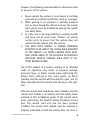
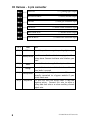
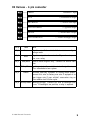
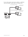
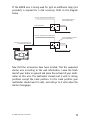
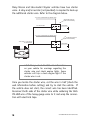
Model 25622
➤Owner’s/Installation
Guide
limited lifetime consumer warranty
Directed Electronics (hereinafter "Directed") promises to the original purchaser to repair
or replace with a comparable reconditioned Directed remote start unit if this Directed
remote start unit (hereinafter "Unit"), excluding without limitation, any remote transmitters or associated accessories, proves defective in materials or workmanship under normal use for the life of the vehicle which the Unit is originally installed. During this period, so long as the Unit remained installed in the original vehicle, Directed will at its
option, repair or replace this Unit if it is proved defective in workmanship or material
PROVIDED the Unit is returned to Directed's warranty department at One Viper Way,
Vista, CA 92081, along with $20 postage and handling fee, a bill of sale or other dated
proof of purchase bearing the following information: Date of purchase, name and location of the merchant who sold the Unit, and product description. This warranty does not
cover labor costs for the removal or reinstallation of the Unit. This warranty is non-transferable and does not apply to any Unit that has been modified or used in a manner contrary to its intended purpose, and this warranty does not cover damage to any Unit caused
by installation or removal of the Unit. This warranty is void if the Unit has been damaged by accident or unreasonable use, neglect, improper service or other causes not arising out of defects in materials or workmanship. Directed makes no warranty against theft
of a vehicle or its contents.
THE FOREGOING WARRANTY IS THE EXCLUSIVE PRODUCT WARRANTY,
OTHERWISE, ALL WARRANTIES INCLUDING BUT NOT LIMITED TO
EXPRESS WARRANTY, IMPLIED WARRANTY, WARRANTY OF MERCHANTABILITY, OR FITNESS FOR A PARTICULAR PURPOSE ARE EXPRESSLY
EXCLUDED AND DISCLAIMED TO THE MAXIMUM EXTENT ALLOWED BY
LAW, AND DIRECTED NEITHER ASSUMES NOR AUTHORIZES ANY PERSON
TO ASSUME FOR IT ANY LIABILITY IN CONNECTION WITH THE SALE OF
THE PRODUCT. DIRECTED HAS ABSOLUTELY NO LIABILITY FOR ANY
AND ALL ACTS OF THIRD PARTIES INCLUDING ITS AUTHORIZED DEALERS OR INSTALLERS. SOME STATES DO NOT ALLOW THE LIMITATION ON
HOW LONG AN IMPLIED WARRANTY LASTS, SO THE ABOVE LIMITATION
MAY NOT APPLY TO YOU.
LIMITATION OF DAMAGES AND LIABILITY. CONSUMER'S REMEDY IS LIMITED TO REPAIR OR REPLACEMENT OF THE UNIT, AND IN NO EVENT
SHALL DIRECTED'S LIABILITY EXCEED THE PURCHASE PRICE OF THE
UNIT. IN ANY EVENT, DIRECTED SHALL NOT BE LIABLE FOR ANY DAMAGES INCLUDING, BUT NOT LIMITED TO, ANY DIRECT, INDIRECT, INCIDENTAL, SPECIAL, PUNITIVE OR CONSEQUENTIAL DAMAGES, LOST
PROFITS, LOST SAVINGS, OR, TO THE EXTENT ALLOWED BY APPLICABLE
LAW, DAMAGES RESULTING FROM DEATH OR INJURY ARISING OUT OF
© 2006 Directed Electronics
i
OR IN CONNECTION WITH THE INSTALLATION, USE, IMPROPER USE, OR
INABILITY TO USE, THE PRODUCT, EVEN IF THE PARTY HAS BEEN
ADVISED OF THE POSSIBILITY OF SUCH DAMAGES. SOME STATES DO
NOT ALLOW THE EXCLUSION OF LIMITATION OF INCIDENTAL OR CONSEQUENTIAL DAMAGES, SO THE ABOVE LIMITATIONS OR EXCLUSION
MAY NOT APPLY TO YOU. THE CONSUMER AGREES AND CONSENTS THAT
ALL DISPUTES BETWEEN THE CONSUMER AND DIRECTED SHALL BE
RESOLVED IN ACCORDANCE WITH CALIFORNIA LAWS IN SAN DIEGO
COUNTY, CALIFORNIA.
IMPORTANT NOTE:
This product warranty is automatically void if its date code or serial number is defaced,
missing, or altered.
Make sure you have all of the following information from your dealer:
A clear copy of the sales receipt, showing the following:
➤
➤
➤
ii
Date of purchase
Authorized dealer's company name and address
Item number
© 2006 Directed Electronics
table of contents
limited lifetime consumer warranty . . . . . . . . . . . . . . . . . . . . . . . . . . . . . . . . . . . . . . . . i
Install Guide . . . . . . . . . . . . . . . . . . . . . . . . . . . . . . . . . . . . . . . . . . . . . . . . . . . . . . . . 3
what is included . . . . . . . . . . . . . . . . . . . . . . . . . . . . . . . . . . . . . . . . . . . . . . . . . . 3
installation tools . . . . . . . . . . . . . . . . . . . . . . . . . . . . . . . . . . . . . . . . . . . . . . . . . . 3
important information . . . . . . . . . . . . . . . . . . . . . . . . . . . . . . . . . . . . . . . . . . . . . 4
system maintenance . . . . . . . . . . . . . . . . . . . . . . . . . . . . . . . . . . . . . . . . . . . . . . 4
Wiring Quick Reference Guide . . . . . . . . . . . . . . . . . . . . . . . . . . . . . . . . . . . . . . . . . . 7
H1 Harness - 6 pin connector . . . . . . . . . . . . . . . . . . . . . . . . . . . . . . . . . . . . . . . 8
H2 Harness - 6 pin connector . . . . . . . . . . . . . . . . . . . . . . . . . . . . . . . . . . . . . . . 9
relay heavy gauge wires. . . . . . . . . . . . . . . . . . . . . . . . . . . . . . . . . . . . . . . . . . . . 10
Installation Overview . . . . . . . . . . . . . . . . . . . . . . . . . . . . . . . . . . . . . . . . . . . . . 11
Step 1, Heavy Gauge Wire Connections . . . . . . . . . . . . . . . . . . . . . . . . . . . . . . 12
Step 2, H1, Main Harness Connections. . . . . . . . . . . . . . . . . . . . . . . . . . . . . . . 19
Step 3, H2 Harness . . . . . . . . . . . . . . . . . . . . . . . . . . . . . . . . . . . . . . . . . . . . . . 23
Step 4, Immobilizer Bypass Modules . . . . . . . . . . . . . . . . . . . . . . . . . . . . . . . . . 28
Step 5, Programming . . . . . . . . . . . . . . . . . . . . . . . . . . . . . . . . . . . . . . . . . . . . . 29
Remote Start Diagnostics . . . . . . . . . . . . . . . . . . . . . . . . . . . . . . . . . . . . . . . . . . 35
Testing the system . . . . . . . . . . . . . . . . . . . . . . . . . . . . . . . . . . . . . . . . . . . . . . . 38
Troubleshooting . . . . . . . . . . . . . . . . . . . . . . . . . . . . . . . . . . . . . . . . . . . . . . . . . 41
Owner’s Guide . . . . . . . . . . . . . . . . . . . . . . . . . . . . . . . . . . . . . . . . . . . . . . . . . . . . . 44
Remote Start Features . . . . . . . . . . . . . . . . . . . . . . . . . . . . . . . . . . . . . . . . . . . . 45
Glossary of terms . . . . . . . . . . . . . . . . . . . . . . . . . . . . . . . . . . . . . . . . . . . . . . . . 51
Notes . . . . . . . . . . . . . . . . . . . . . . . . . . . . . . . . . . . . . . . . . . . . . . . . . . . . . . . . . . . . . 52
quick reference guide: . . . . . . . . . . . . . . . . . . . . . . . . . . . . . . . . . . . . . . . . . . . . . . . . 53
© 2006 Directed Electronics
1
2
© 2006 Directed Electronics
Install Guide
what is included
Control Module
6-Pin Main H1 Harness
6-Pin H2 Secondary Harness
Heavy Gauge Wires
Crash code card
Combination Momentary Switch and LED
Hood Pin Switch
Hardware Kit
Additional parts may be required (such as relays or bypass).
installation tools
Digital Multi-Meter
Drill
1
/4 Drill Bit (for hood pin switch)
Screwdrivers (Phillips and Flathead)
Wire Stripper
Solder Iron
Electrical Tape
Pliers
Crimping Tool
note: The installation tools listed above may be
optional and those required will vary depending on
your vehicle.
© 2006 Directed Electronics
3
important information
Congratulations on the purchase of your remote start system. This
system is designed to integrate with your existing keyless entry or
alarm system. Properly installed, this system will provide years of
trouble-free operation.
Please take the time to carefully read this User’s Guide in its
entirety prior to installing your system.
You can print additional or replacement copies of this manual
by
accessing
the
Directed
web
site
at
www.autocommand.com.
important! If you are not comfortable working with
electronics or unfamiliar with the tools required,
please contact your local dealer for advice or ask to
have the remote start professionally installed to avoid
costly damages. Failure to properly install the remote
starter may result in property damage, personal injury,
or both.
➜ system maintenance
After the installation is completed the system requires no
specific maintenance.
warning! safety first
The following safety warnings must be observed at all times:
When properly installed, this system can start the vehicle
via input from your existing keyless entry or alarm
system. Therefore, never operate the system in an area
that does not have adequate ventilation. The following
precautions are the sole responsibility of the user;
4
© 2006 Directed Electronics
however, the following recommendations should be made
to all users of this system:
1. Never operate the system in an enclosed or partially
enclosed area without ventilation (such as a garage).
2. When parking in an enclosed or partially enclosed
area or when having the vehicle serviced, the remote
start system must be disabled by placing the system
into Valet Mode.
3. It is the user's sole responsibility to properly handle
and keep out of reach from children all remote
control units to assure that the system does not
unintentionally remote start the vehicle.
4. THE USER MUST INSTALL A CARBON MONOXIDE
DETECTOR IN OR ABOUT THE LIVING AREA ADJACENT
TO THE VEHICLE. ALL DOORS LEADING FROM ADJACENT LIVING AREAS TO THE ENCLOSED OR PARTIALLY
ENCLOSED VEHICLE STORAGE AREA MUST AT ALL
TIMES REMAIN CLOSED.
Use of this product in a manner contrary to its intended
mode of operation may result in property damage,
personal injury, or death. Except when performing the
Safety Check outlined in this user’s guide, (1) Never
remotely start the vehicle with the vehicle in gear, and (2)
Never remotely start the vehicle with the keys in the ignition.
After the remote start module has been installed, test the
remote start module in accordance with the Safety Check
outlined in this installation guide. If the vehicle starts
when performing the Neutral Safety Shutdown Circuit
test, the remote start unit has not been properly
installed. The remote start module must be removed or
properly reinstalled so that the vehicle does not start in
© 2006 Directed Electronics
5
gear. OPERATION OF THE REMOTE START MODULE IF THE
VEHICLE STARTS IN GEAR IS CONTRARY TO ITS INTENDED
MODE OF OPERATION. OPERATING THE REMOTE START
SYSTEM UNDER THESE CONDITIONS MAY RESULT IN PROPERTY DAMAGE OR PERSONAL INJURY. IMMEDIATELY CEASE
THE USE OF THE UNIT AND REPAIR OR DISCONNECT THE
INSTALLED REMOTE START MODULE. DIRECTED WILL NOT BE
HELD RESPONSIBLE OR PAY FOR INSTALLATION OR REINSTALLATION COSTS.
6
© 2006 Directed Electronics
© 2006 Directed Electronics
MOMENTARY SWITCH
BLUE
PINK
GREEN (+) output to ign/acc2 circuit
Heavy Gauge
Wires
H1
H2
Black (-)
Heavy guage
ground wire
YELLOW/BROWN (-) 400mA Headlight output
BROWN (-) 400mA RAP, Factory Alarm rearm
YELLOW/GREEN (+) ignition output
RED/BLACK (-) wait-to-start input
BLUE (-) 400mA horn/siren output
GREEN Tachometer input
RED/WHITE (-) remote start activation
WHITE/BLACK (-) 400mA status output
ORANGE (+) brake input
VIOLET (-) negative hood pin shutdown output
BROWN/WHITE (-) factory alarm disarm output
YELLOW (+/-) parking light output
Fused light
flash jumper
WHITE (+)
PINK
YELLOW
Wiring Quick Reference Guide
7
H1 Harness - 6 pin connector
H1/1
___ YELLOW
H1/2
___ BROWN/WHITE
H1/3
___ VIOLET
H1/4
___ ORANGE
H1/5
___ WHITE/BLACK
H1/6
___ RED/WHITE
(+/-) parking light output
(-) factory disarm output
(-) hood pin shutdown input
(+) brake switch shutdown input
(-) 400mA status output
(-) remote start activation input
Pin #
Color
Note
H1/1
Yellow
Selectable positive or negative parking light output
H1/2
Brown/White Use this wire if the vehicle is equipped with a
factory alarm. Connect to disarm wire listed on your
sheet.
H1/3
Violet
H1/4
Orange
H1/5
H1/6
8
Connect this wire to supplied hood pin switch
Connect this to wire in vehicle that shows 12 volts
when brake is pressed
White/Black Provides a ground during remote start. This wire is
normally connected to a bypass module if your
vehicle needs one.
Red/White This wire will start the vehicle when it sees two
negative pulses. Connect this wire to either a
factory door lock wire or an alarm auxiliary channel
output wire.
© 2006 Directed Electronics
H2 Harness - 6 pin connector
H2/1 ___ GREEN
H2/2
___ BLUE
H2/3
___ RED/BLACK
H2/4
___ YELLOW/GREEN
H2/5
___ BROWN
H2/6
___ YELLOW/BROWN
Pin #
Tachometer input
(-) 400mA horn output
(-) wait-to-start input
(+) ignition output
(-) 400mA RAP Output
(-) 400mA headlight output
Note
H2/1
Color
Green
H2/2
Blue
H2/3
Red/Black
Negative output to horn circuit. If your horn is positive, use a relay.
Used on diesel engines only. Connects to wait-to-start
wire
Use this wire if the vehicle fails to start correctly in
voltage mode
H2/4 Yellow/Green Ignition output. Connect this wire to the ignition input
of an aftermarket alarm system.
H2/5
Brown
Retained accessory shutdown or factory rearm output.
Connect this wire to factory arm wire if equiped or to
door trigger wire if your vehicle’s accessories stay on
after remote start finishes cycle.
H2/6 Yellow/Brown Headlight output. Connect this wire to headlight wire
in car. If headlights are positive, a relay is required.
© 2006 Directed Electronics
9
relay heavy gauge wires
1 ___ GREEN
2
___ PINK
(+) 12 volt input
3
___ BLUE
(+) ignition 1 output
4
___ WHITE
5
___ PINK
(+) 12 volt input
6
___ YELLOW
(+) starter output
BLACK
10
(+) Ign2 or Acc2 output
(+) accessory output
(-) ground
© 2006 Directed Electronics
Installation Overview
Be sure to read this section thoroughly and in its entirety before
starting the installation. Pay special attention to all warnings to
prevent personal injury or damage to your vehicle.
Visit our 24-hour technical web site (www.autocommand.com) to
get a vehicle-specific wiring guide prior to starting this installation.
Have your crash code number handy when contacting tech support
or visiting the web site. During the installation if you are unable
to find answers to your questions on the web site, call 1-800-4771382 for live technical assistance. Please note that live technical
support is available Monday-Friday 6am-6pm PST, and SaturdaySunday 7am-3:30pm PST.
WARNING!
➤
➤
➤
Verify that the transmission is set to park and that
the parking brake is set before beginning installation.
On vehicles with air bags or supplemental restraint
systems (SRS) you may notice a bright yellow tube
with small wires in it marked SRS underneath the
steering column near the key cylinder. DO NOT tamper
or unplug these for any reason to prevent costly damages to your vehicle or personal injury. Tampering
may cause unintended deployment of airbags.
This system is intended for automatic, fuel-injected
vehicles only. Installation in any other vehicle is contrary to its intended use.
© 2006 Directed Electronics
11
Step 1, Heavy Gauge Wire Connections
Ground Wire
The BLACK wire connects to the pin next to the light flash jumper
fuse. First strip back a ¾-inch section of the insulation off the
BLACK wire and crimp a ring terminal (not provided) to that wire.
Locate a clean, paint-free metal surface in the drivers kick panel
(do not ground on dash). Using a self-tapping screw, drill the
screw with the ring terminal to the kick panel. Once screwed down,
pull on the wire to ensure a good connection.
SELF-TAPPING
BOLT OR SCREW
GROUND
WIRE
DIA-591
NOTE: REMOVE ANY PAINT
BELOW RING CONNECTOR
RING
TERMINAL
note! More problems are attributed to poor ground
connections than any other cause. Take extra care
to ensure the ground is a clean metal-to-metal
contact and secure.
Constant Power and Ignition wires
Almost all your power and ignition wires can be found behind the
key cylinder under the lower driver's side dash panel. Using the
appropriate hand tools, remove the lower dash panel taking care
not to break any parts. If the panel does not come off easily, check
for any additional screws you may have missed.
12
© 2006 Directed Electronics
Once the lower dash panel has been removed, locate the ignition
harness at the back of the key cylinder. This is usually a group of
heavy gauge wires (approximate 14ga.).
Place the black lead of the LED tester to a clean metal surface in
the kick panel area and secure it. Probe one of the thicker gauge
wires. The ignition wire colors of your specific vehicle can be
obtained at www.autocommand.com.
Testing for Constant Power Wires
WARNING! Before making any connection to constant
battery power make sure that the two 30 amp fuses
are removed from the fuse holders on the two pink 12
VOLT wires. Failure to do so may cause fire or shorting of sensitive electrical components.
© 2006 Directed Electronics
13
With the key in the off position, test the suspect wire. The
constant power wire will read 12V on the multimeter. Once the
constant power wire has been identified, solder the two heavy
gauge 12 VOLT wires (PINK) from the control module to it and
wrap the connection with electrical tape.
note! If the vehicle has more than one constant
power wire, utilize two of them. Connect one of the
heavy gauge PINK wires to one of the constant
power wires and the other heavy gauge PINK wire to
the other constant power wire.
Testing for Ignition Wires
With the multimeter lead still connected in the kick panel, locate
the suspected ignition wire. It will test differently than constant
12 volts. Place the red lead of the multimeter on the suspected
wire. With the key in the off position the multimeter will read 0.
Turn the key to the on position and the multimeter will read 12
volts. Now, watching your multimeter, turn the key to the crank
position. If the 12 volts stays on, then you have found your ignition wire. If the wire tests correctly, solder the BLUE heavy gauge
wire to it and wrap the connection with electrical tape.
If the vehicle requires more than one ignition as per the web site
information, follow the same test procedure and solder the GREEN
heavy gauge wire to it then wrap the connection with electrical
tape. If your vehicle has only one ignition wire, secure the GREEN
wire and dress it out of the way.
14
© 2006 Directed Electronics
If your vehicle requires more than two ignitions, an additional
relay (not provided) is required. Refer to the diagram below.
+12 VDC CONSTANT (FUSED 20A)
2nd IGNITION RELAY
(NOT PROVIDED)
TO 2nd IGNITION
87
86
GROUND
87A
30
85
TO 2nd IGNITION
+12 VDC CONSTANT (FUSED 20A)
3rd IGNITION RELAY
(NOT PROVIDED)
GREEN (+) OUTPUT
TO 2nd IGNITION
87
86
87A
30
GROUND
85
TO 3rd IGNITION
© 2006 Directed Electronics
15
Accessory and Starter wires
The starter and accessory wires will be located in the same harness
as the ignition and constant power.
To find the accessory wire leave the multimeter’s black lead
connected to ground. Take the red lead and probe the wire
suspected to be the accessory wire. With the key off, your multimeter should read 0 volts. Turn the key to the on position the
multimeter should read 12 volts. Now turn the key to the crank
position. If you have the correct accessory wire the multimeter
will read 0 volts while the starter is cranking and 12 volts once
the key returns to the on position. If the wire tests correctly, strip
some insulation off and solder the WHITE heavy gauge wire and
wrap it with electrical tape.
If your vehicle requires more than one accessory then the GREEN
ign2 wire can be programmed to function as an accessory output.
16
© 2006 Directed Electronics
If the GREEN wire is being used for ign2 an additional relay (not
provided) is required for a 2nd accessory. Refer to the diagram
below.
+12 VDC CONSTANT (FUSED 20A)
ACCESSORY RELAY
(NOT PROVIDED)
87
TO ACCESSORY
86
GROUND
87A
30
85
TO ACCESSORY
+12 VDC CONSTANT (FUSED 20A)
2nd ACCESSORY RELAY
(NOT PROVIDED)
WHITE (+) 30A OUTPUT TO
ACCESSORY CIRCUIT
87
86
GROUND
87A
30
85
TO 2nd ACCESSORY
Now that the accessories have been located, find the suspected
starter wire according to the web information. Leave the black
lead of your tester on ground and place the red lead of your multimeter on this wire. The multimeter should read 0 volts in all key
positions except the crank position. In the crank position your
multimeter should read 12 volts, and will go to 0 volts when the
starter disengages.
© 2006 Directed Electronics
17
Many Nissan and late-model Chrysler vehicles have two starter
wires. A relay and/or resistor (not provided) is required to hook up
the additional starter wire. Refer to the diagram below.
+12 VDC CONSTANT (FUSED 20A)
STARTER RELAY
(NOT PROVIDED)
87
TO STARTER
86
GROUND
87A
30
85
TO STARTER
+12 VDC CONSTANT (FUSED 20A)
2nd STARTER RELAY
(NOT PROVIDED)
YELLOW (+) OUTPUT
TO STARTER
87
86
GROUND
87A
30
85
TO 2nd STARTER
note! Always check the Web site information
on your vehicle for warnings regarding the
starter wire and check engine lights. Some
vehicles will trip a check engine light if the
starter wire is cut.
Once you locate the starter wire, cut the wire in half (check the
web information before cutting) and try to start the vehicle. If
the vehicle does not start, the correct wire has been identified.
Reconnect both ends of the starter wire while soldering the thick
YELLOW wire of the heavy guage wires to it and wrap the connection with electrical tape.
18
© 2006 Directed Electronics
Step 2, H1, Main Harness Connections
Factory Alarm Disarm
Since many newer vehicles come equipped with a factory alarm it
is necessary to disarm it during remote start. Do not mistake a
factory alarm with an immobilizer system. They each require
different disarm operations.
Locate the factory alarm disarm wire using the web site information. Once the suspect wire is located, place the multi-meter's red
lead to a (+)12 volt constant source and secure it. Put the multimeter in the DC position then probe the suspect wire with the
black lead of your meter. While probing the wire, place the key in
the driver's door cylinder. Turn it to the unlock position and hold
it when testing for the disarm wire. The multimeter should read
12V and will go back to 0V when the key is released.
When the correct wire has been found, solder the BROWN/WHITE
wire of the 6-pin harness to the wire that you determined to be
the factory alarm disarm wire. After this wire has been connected
wrap the connection with electrical tape.
note! On some vehicles the Factory Alarm Disarm
wire is connected to a Body Control Module or a Door
Module. If you find this configuration, please call
Technical Support at 1-800-477-1382.
note! Some vehicles use a + trigger factory alarm
system. Use the website to determine if your vehicle
has a + trigger. If your vehicle has such a system call
1-800-477-1382 for live technical assistance as special wiring and an additional relay is required.
© 2006 Directed Electronics
19
Parking light flash
There are several different types of parking light circuits. The
following description is for a standard positive-triggered parkinglight circuit, only. If the web vehicle information suggests a (-)
parking light circuit, the fuse jumper (on the side of the module)
must be moved to the opposite position.
The default position for this jumper is for a positive parking light
circuit.
Using the web information on the vehicle, locate the suspected
wire. Connect the black multimeter lead to ground in the kick
panel. Probe the suspected wire with the red lead of your meter.
With the switch in the off position the multimeter should read 0
volts. While watching the multimeter, turn your headlight switch
to the parking light position. The multimeter should read 12 volts.
While testing the suspected wire, run the dash dimmer light
control up and down-the voltage should NOT vary. If the voltage
does vary then this is the wrong wire. Continue probing to find the
correct wire.
Once you have identified the correct wire, solder the small YELLOW
wire of the 6-pin harness to it and wrap the connection with electrical tape.
important! Remember this description is for a (+)
parking light circuit. A (-) circuit will test differently.
Also, if the web information requires using resistors
for parking lights, contact Technical Support.
20
© 2006 Directed Electronics
Safety Shutdown Wires
With all ignition wires properly connected, find the appropriate
safety shutdown wires. These are the brake wire and hood pin
wires.
WARNING! These wires are meant to protect the
vehicle and anyone near the vehicle. They MUST
be connected to prevent damage to the vehicle
and possible bodily injury.
First locate the factory brake wire using your multimeter. Find the
switch at the top of the metal arm coming off the brake pedal. Use
your vehicle specific wiring information to determine the color of
this wire. With the black lead of your multimeter still in the kick
panel, probe the suspected wire with the red lead of your multimeter. With the brake pedal at rest the multimeter should read 0
volts. While watching the multimeter, depress the brake pedal.
The multimeter should read 12 volts. Once you have located the
correct brake wire, solder the small ORANGE wire in the 6-pin
harness to it and wrap the connection with electrical tape.
WARNING! Do not use the vehicle until you
confirm the operation of the brake shutdown.
Installing the hood pin switch requires drilling a hole in a metal
lip under the hood. Choose a location that will allow the pin
switch to be completely depressed when the hood is closed. The
pin switch has a spade connector on the bottom for the wire
connection.
Crimp your spade connector to the hood pin wire and run the wire
into the vehicle's passenger compartment through a factory rubber
grommet (at the same time you might want to run Tachometer
Input wire and Horn output wire from Optional Harness through
the fire wall as you may need to connect them using the following
steps).
© 2006 Directed Electronics
21
Using a sharp, pointed object poke a hole into the grommet
(being careful not to damage any existing wires in the grommet)
and attach the wire to the object with electrical tape. Pull the
wire through the grommet taking extra care to keep the wire away
from any moving parts or anything that will generate extreme
heat.
An alternative to this method would be to find a spot on the firewall with sufficient clearance on both sides and drill an access
hole through the firewall. Take note of what is directly on the
other side of where you are drilling as to not puncture brake cylinders, computers, etc. Once the wire is run into the vehicle and
secured from any moving parts, solder the wire to the VIOLET wire
of the 6-pin harness and wrap the connection with electrical tape.
WARNING! This wire MUST be connected. Do not
use the vehicle until you confirm the operation
of the hood pin shutdown. Improper operation
could result injury or death.
22
© 2006 Directed Electronics
Step 3, H2 Harness
Engine Monitoring Explained
During remote start the system will need to know if the engine is
running. The module does this by monitoring the voltage of the
vehicle's electrical system (or the tachometer-see next section).
Voltage Monitoring
note! If the system has been programmed for
Tachometer monitoring previously, it must be
reprogrammed to Voltage monitoring.
Vehicle electrical systems usually rest at about 12.6 volts when
the engine is not running. This system is programmed to detect
the rise in battery voltage that occurs when the charging circuit
activates after starting, and keep the engine running if the rise is
adequate. It will make up to three start attempts before discontinuing due to an inadequate voltage rise.
Some vehicles have alternators that do not activate immediately
or do not increase voltage sufficiently after starting, this system
will compensate by delaying the time before reading the battery
voltage on the second and third start attempts. This delay will
allow most alternators to activate so the remote start will
continue to run.
The voltage read times are:
First attempt: 10 seconds
Second attempt: 20 seconds
Third attempt: 50 seconds
After the third start attempt, if the voltage increase is still not
adequate to keep the engine running, the Tachometer input
option should be used to monitor the engine.
© 2006 Directed Electronics
23
Tachometer Wire
WARNING! In the following procedure DO NOT use
a test light. Use of this type of tester can cause
grounding of sensitive electrical components causing damage, including damage to the power train
control module. A digital multi-meter is required to
test for this wire.
Do not wear loose clothing that could get entangled
in rotating engine components. Ensure that your
hands and arms are well clear of these rotating
components when working in the engine compartment. Lastly, ensure that all wires and tools are
clear of falling into or entanglement with these
rotating components.
Identify the suspected tach wire according to the web information. Next, place the black lead of a MULTI-METER on the negative battery post and secure it. Put the multi-meter in the AC position and connect the probe to the suspect wire with the red lead
of the multi-meter. Then start the vehicle with the key. With the
engine at idle the multi-meter should read between .50 volts to 6
volts, and should fluctuate when you rev the engine.
Have a second person press the gas pedal to increase the RPMs
and watch the meter display. When the RPMs increase the voltage
should rise slightly (not all tachometer outputs will rise when
engine RPM increases). Once the correct tachometer wire has been
identified, turn the vehicle off.
Run the GREEN wire from the 8-pin harness through the firewall
into the engine compartment along side the hood pin wire. Use
the same procedure as with the hood pin wire and pull the wire
through the grommet taking extra care to keep it away from any
moving parts or anything that will generate extreme heat. Once
the wire is run into the engine compartment, strip a small portion
24
© 2006 Directed Electronics
of insulation off the tachometer wire in the vehicle and solder the
green tachometer input wire to it. Then wrap the connection with
electrical tape.
note! If using a tach signal, the tach signal MUST
be learned before using the remote starter.
LEARNING YOUR TACH SIGNAL
If using a tach wire, you must learn the tach signal after
completing the installation.
To learn tach signal:
1.
Start car with key
2.
Wait about 5 seconds for the engine to idle down
3.
Press and hold the Momentary switch (about 10
seconds)
4.
Tach learned: After a few seconds the LED will flash 2
times and turn on. Continue to hold the switch for 2 - 3
seconds and release.
5.
Tach not learned: The LED will not turn on and will flash
3 times when the momentary switch is released. Check
the connections and try again.
© 2006 Directed Electronics
25
Following is a brief description of the remainder of the wires in
the H2 harness. For specific details on connecting these outputs
contact Technical Support at 1-800-477-1382.
Horn wire
The Blue wire provides an output for activating the vehicle horn
circuit during remote start.
important! This is a low current output and that
requires an external relay when connected to circuits
that draw more than 400mA in current.
Wait-to-start wire
The Red/Black wire is for use with diesel engines that require a
short delay for the glow plugs to warm up before cranking the
engine. Connect this wire to the wire in the vehicle that sends the
signal to turn on the WAIT-TO-START bulb in the dashboard. In
most diesels the wire is negative (ground turns on the bulb) and
the Red/Black wire can be directly connected. If the vehicle uses
a positive wire (12V to turn on the bulb) a relay must be used to
change the polarity.
Ignition Output wire
The Yellow/Green wire should be the ONLY the ignition input to an
existing aftermarket alarm system. This wire will prevent the host
system from sensing that the ignition is on during remote start
operation.
RAP or Retained Accessory Power
The BROWN wire is designed to turn off accessories that remain on
after the ignition is turned off. It will pulse 10 seconds after the
remote start status output ceases and will make the vehicle body
control module think the door has opened, thus turning the accessories off.
26
© 2006 Directed Electronics
important! this is a low current output and that
requires an external relay when connected to circuits that draw more than 400mA in current.
Headlight Control wire
The Yellow/Brown wire provides an output for activating the
vehicle headlight circuit. It is programmable in Feature Menu
1/10 for the type of ignition controlled activation.
important! this is a low current output and that
requires an external relay when connected to circuits that draw more than 400mA in current.
© 2006 Directed Electronics
27
Step 4, Immobilizer Bypass Modules
Most newer vehicles have a factory engine immobilizer system
designed to prevent any unauthorized use of the vehicle. These
immobilizers will cut off power to the starter and the fuel supply
preventing a thief from starting the vehicle.
There are several types of immobilizers, with the most common
being the resistance-based passlock/passlock 2 systems found on
most newer GM vehicles. This system can be bypassed using the
20402, 29402 or 556L immobilizer bypass modules available at
your local authorized retailer or at www.directedstore.com. The
majority of transponder-based immobilizer systems can be
bypassed using the 20402, 29402 or 556U immobilizer bypass
module available at your local authorized retailer.
The WHITE/BLACK wire of the 6-pin harness supplies a 400mA (-)
output as soon as the control module begins the remote start
process. This wire can be used to activate an immobilizer bypass
unit.
note! Any vehicle equipped with a factory immobilizer must use an immobilizer bypass module to
remote start. If not used, the vehicle ignition or
fuel supply circuits could lock up and require a
costly trip to the dealer to reset the computer system.
To determine which bypass module your vehicle requires, use the
website
Interface
Module
Look-Up
tool
at
www.autocommand.com.
28
© 2006 Directed Electronics
Step 5, Programming
Programming System Settings
Many of the features and operations of this system can be changed
to suit most of today's vehicle electrical systems. The programming routine and feature menus that follow will allow making the
changes required for most vehicle installations.
System programming routine:
Accessing a Menu:
1.
Turn the ignition ON and then OFF in less than 5 seconds
2.
Within 3 seconds Press/Hold the Momentary Switch
3.
After 2 seconds the LED will flash once and Horn will
pulse once and repeat.
4.
Release the Momentary Switch to access the menu. The
LED and Horn outputs will cease.
Accessing a Feature Location:
1.
Press and release (do not hold) the Momentary Switch
the same number of times as the feature location to be
accessed. See the Feature Chart for locations.
2.
After 2 seconds the LED will flash (the number of flashes
will match with the feature location) to confirm the
feature location. It will flash/pause and repeat until the
feature is changed or programming is exited.
3.
Pulse the Red/White activation input wire. Each pulse
will toggle through each of the available options. The
LED and Horn outputs will pulse to indicate the selected
option.
© 2006 Directed Electronics
29
a. Option 1: The LED will turn ON and the Horn will pulse
once.
b. Option 2-4: The LED will flash and the Horn will pulse
2-4 times to indicate the option and the LED will
continue to flash to indicate the option.
Return to the beginning of the Menu:
To return to the beginning of the menu at any time, press and hold
the Momentary Switch for 2 seconds.
Advance to different feature location:
To advance to a new location within the same menu press/release
the Momentary Switch the same number of times as the difference
between the feature locations.
example! to advance from feature location 2 to feature
location 8 press/release (do not hold) the Momentary
switch 6 times, after 2 seconds the LED will flash 8
times to indicate the newly accessed feature location.
Exiting Feature programming:
The following will cause the system to exit programming and is
indicated by 5 short chirps of the Horn output.
a. More than 15 seconds lapses between inputs by
Momentary switch or activation input
b. The ignition is turned on
30
© 2006 Directed Electronics
Feature Menu
Feature Menu 1 Chart
Feature
Location
Feature Name
Option 1
(Default)
Option 2
Option 3
Option 4
1
Engine Monitoring
No Tach
Tach
NA
NA
2
Run Time
15 min
30 min
NA
NA
3
Crank time
Normal
ExtraCrank
Super crank
Mega crank
4
Ign2 Output
Ign 2
ACC 2
NA
NA
5
Wait-to-start
Diesel Input
wire
Diesel Timer
NA
NA
6
Activation Input
2 pulse
1 pulse
NA
NA
7
Vacation Temp
0 degrees F
-10 degrees F
-20 degrees F
NA
8
Alarm Disarm
1 second
450 ms
NA
NA
9
NA
NA
NA
NA
NA
10
Headlights
Daytime
Light your
way
NA
NA
11
Start Chirp
On
Off
NA
NA
12
NA
NA
NA
NA
NA
13
Reset All Options
© 2006 Directed Electronics
Pulse the activation input wire to reset all
features
31
Feature Menu 1 Descriptions
1. Engine Monitoring: Defines how the engine is monitored while
the Remote Start is active.
1. No Tach: The battery voltage will be used to monitor the
engine while Remote Start is active.
2. Tachometer: The tachometer will be used to monitor
engine speed while Remote Start is active.
2. Run Time
1.
15 minutes: The Remote Starter will shut down after it
has been active for 15 minutes.
2.
30 minutes: The Remote Starter will shut down after it
has been active for 30 minutes.
3. Crank Time: Crank Time will be in effect only when Engine
Monitoring is "No Tach" and affects the duration of the "Yellow"
Starter Output wire.
1.
Normal Crank: The Starter output will be 700mS.
2.
Extra Crank: The Starter output will be 1 second.
3.
Super Crank: The Starter output will be 1.4 seconds.
4.
Mega Crank: The Starter output will be 2.1 seconds.
4. Ignition 2 Output: This controls the output type of the high
current "Green" ignition 2 output wire.
32
1.
Ignition 2: Output will match the Blue Ignition 1
input/output wire operation during remote start.
2.
Accessory 2: Output will match the White Accessory 1
output wires operation.
© 2006 Directed Electronics
5. Wait-To-Start: This chooses the method of Starter output delay
for Diesel engines.
1.
Diesel Input wire: An input on the "Red/Blk" wire will
delay the Start output until the input ceases.
2.
Diesel Timer: The Starter output will be delayed 15
seconds. The "Red/Blk" wire will be ignored.
6. Activation Input: Selects the number of pulses on the
"Red/Wht" activation input wire to activate the Remote Starter.
1.
2 Pulses: Two input pulse will Start and Stop the Remote
Starter
2.
1 Pulse: One input pulse will Start and Stop the Remote
Starter
7. Vacation Temp: Selects the temperature threshold that will activate the Remote Starter when Vacation Mode has been activated.
1. 0 Degrees F
2. -10 Degrees F
3. -20 Degrees F
8. Alarm Disarm: Selects the output duration of the "Brown/Wht"
Factory Alarm Disarm wire.
1. 1 second: The output will be 1 second in duration
2. 450mS: The output will be 450mS in duration
9. NA: A feature is not available for this location
10. Headlights: Selects the operation of the "Yellow/Brn" headlight output wire when an ignition input is sensed.
1.
Daytime Running: The output will activate 10 seconds
© 2006 Directed Electronics
33
after an ignition input is sensed and cease output 1
second after the ignition input ceases.
2.
LightYourWay: The output will activate for 25 seconds
immediately after the ignition input ceases.
11. Start Chirps: Selects if the "Blue" Horn output wire will pulse
when activating Remote Starter.
1.
On: The Horn output will pulse 1 time at the beginning
of Remote Start
2.
Off: The Horn output WILL NOT pulse at the beginning
of Remote Start
12. NA: A feature is Not Available for this Location
13. Reset All Options: Pulse the activation input wire when this
Feature Location is accessed will "Reset All Options" to their
default setting.
34
© 2006 Directed Electronics
Remote Start Diagnostics
Remote Start Diagnostics:
Remote Start diagnostics are an important tool that will diagnose the status of the remote start system by letting you know
why it remote started, shut down or refused to start as
expected.
No Start Diagnostics:
If the system fails to activate Remote Start, QuickStop, Daily
Start or Vacation mode as expected the parking lights will flash
to indicate the reason. Consult the No Start Diagnostic Chart for
the reason.
No Start Diagnostic Chart
Remote Start
Feature
Any
LED
Description
Flashes
Indicates a loss of power to the main unit.
0
Daily Start
3
Vacation Mode
3
Remote Start
5
Quickstop
5
© 2006 Directed Electronics
The unit is in the Valet Mode or Battery Voltage is
below 11v when attempting to activate this
feature.
The unit is in the Valet Mode, Battery Voltage is
below 11v, or the Brake, Hood or Ignition inputs
are active
The unit is in the Valet Mode, Battery Voltage is
below 11v, or the Brake or Hood inputs are active
The unit is in the Valet Mode, Battery Voltage is
below 11v, or the Brake or Hood inputs are active
35
Last Start Diagnostics:
The system holds in memory the reason for the most recent
remote start activation. This diagnostic report must be recalled
using the following operation:
1.
Turn the ignition ON and then OFF in less than 5 seconds
2.
Within 5 seconds press and release the Momentary
Switch
3.
After 2 seconds the LED will flash/pause and repeat 5
times to indicate the cause of the most recent remote
start activation.
4.
Count the LED flashes and consult the Last Start
Diagnostic Chart
Last Start Diagnostic Chart
LED
Flashes
1
36
Description
2
The Remote Starter has not been activated since the main power
was connected
No Diagnostic
3
The Activation Input wire was used to activate the Remote starter
4
Low temperature activated the Remote Starter in Vacation Mode
5
Low battery voltage activated the Remote Starter in Vacation Mode
6
No Diagnostics
7
Daily Start activated the Remote Starter
© 2006 Directed Electronics
Shut Down Diagnostics:
The system holds in memory the reason for the most recent
remote start shut down. This diagnostic report must be recalled
using the following operation:
1.
Step on the foot brake and hold until Step 4 has begun
2.
Turn the ignition ON and then OFF in less than 5 seconds
3.
Within 5 seconds press and release the Momentary
Switch
4.
After 2 seconds the LED will flash/pause and repeat 5
times to indicate the cause of the most recent remote
start shut down.
5.
Count the LED flashes and consult the Shut Down
Diagnostic Chart
Shutdown Diagnostic Chart
LED Flashes Description
1
The programmed Run Time expired
2
The 'Orange' Brake Input wire was activated
3
The Tachometer Input level fell below 50% of learned value
4
No diagnostic
5
The 'Violet' Hood Input wire was activated
6
Battery voltage level fell below required level
7
NA
8
The Tachometer Input level was x3 times learned value for >5sec
9
The "Red/Wht" activation Input was used shut down remote start
© 2006 Directed Electronics
37
Testing the system
Neutral Safety Test
Some vehicles do not have an electrical neutral safety switch.
Instead, a mechanical neutral safety switch that physically interrupts the starter wire is used when the vehicle is in any drive gear.
If the remote start is interfaced before this switch, it will provide
protection from starting in gear.
However, some vehicles combine the column shift mechanism and
the mechanical neutral safety switch into one mechanical part. In
these vehicles, it is impossible to interface the remote start
system before the neutral safety switch. With this type of vehicle,
if the car is left in a drive gear and the remote start system is activated, the vehicle will move and may cause damage to persons or
property.
important! This test must be performed to determine if the vehicle will start while in gear. If the
vehicle attempts to start during this test you
must call Technical Support at 1-800-477-1382
for assistance before using the remote start feature.
Testing the Neutral Safety Switch
note! You must complete the remote start system
installation before doing the following test.
Ensure that the remote start system is functioning normally. This includes connecting to the
brake as a shut-down.
1.
38
Make sure there is adequate clearance to the front and
© 2006 Directed Electronics
rear of the vehicle because it may move slightly.
2.
Make sure the hood is closed and there are no remote
start shut-downs active.
3.
Set the emergency brake.
4.
Turn the key to the "run" position, this will release the
shifter.
5.
Place the shifter in the drive position.
6.
Place your foot directly over the brake pedal, but do not
depress it. Be ready to step on the brake if the starter
engages.
7.
Activate the remote start system.
8.
If the starter does not engage, no additional safety
interfaces are required.
9.
If the starter engages, immediately depress the brake to
shut the remote start system down.
IF THE ENGINE ATTEMPTED TO START THEN THE TEST HAS FAILED
CALL TECHNICAL SUPPORT FOR ASSISTANCE AT 1-800-477-1382
warning! If the vehicle fails this test the remote
start must be disabled until the proper Safety
Interface has been installed that will keep the
vehicle from starting while in gear. Failure to do so
may result in property damage, injury or death.
© 2006 Directed Electronics
39
Remote Start Test
Once steps 1-5 have been completed, the operation of the system
can be tested.
Ensure that the two 30-amp fuses are in the relay harness PINK
wire fuse holders. Make sure that the vehicle is in park with the
emergency brake on and the hood closed. Pulse the activation
input wire 2 times to initiate the remote start function. The
parking lights should flash to confirm the remote start command
has been received, The accessories and ignition should turn on
followed by the starter cranking and the vehicle engine running
(this may take a moment to initiate). Pulse the activation input
wire 2 times again and the engine will stop running. (See
Programming System settings section for 1 press remote start
operation)
This completes the Remote Start testing, if all functions do not
work correctly check your wiring against the manual and verify all
connections. If you still experience problems contact Directed
Technical Support at 1-800-477-1382.
40
© 2006 Directed Electronics
Troubleshooting
➜ The ignition comes on, but the starter will not crank.
Does it start with the key in the ignition? If so, does the vehicle
have an engine immobilizer? Does it start with the brake pedal
depressed? (Make sure to disconnect the brake shutdown when
performing this test.) If so, it may have a brake/starter interlock.
Is the correct starter wire being energized? Check by energizing it
yourself with a fused test lead.
➜ The starter cranks for 1 or 2-seconds but does not start.
The wrong ignition wire is being energized or the system's ignition and accessory wires have been connected backwards. Also,
the vehicle may have two ignition circuits. Try activating the unit
with the ignition key in the "run" position. If the vehicle then
runs normally, retest your ignition system.
➜ The starter continues to crank after the car has started.
Has the tach wire been learned? See the Tach Learning section of
this guide. Is the tach wire receiving the correct information?
Either the wrong tach wire has been used, or a bad connection
exists. Verify that all of the heavy gauge wires are plugged into
the correct tabs on the control unit. If they are incorrectly
connected, the starter could stay engaged.
➜ The climate control system does not work.
Either the wrong accessory wire is being energized or more than
one ignition or accessory wire must be energized in order to
operate the climate control system.
➜ The remote start will not activate.
© 2006 Directed Electronics
41
Check to ensure that the hood is not open and that the brake
pedal is not depressed. Check harnesses and connections. Make
sure the harnesses are fully plugged into the remote start module.
Make sure there are good connections to the vehicle wiring. Check
voltage and fuses. Use a meter and check for voltage between the
RED wire and the BLACK ground wire. If you have less than battery
voltage, check both 30A fuses on the main power wires. Also make
sure that the ground wire is going to a good paint-free chassis
ground.
➜ The remote start will activate but the starter never engages.
1. Check for voltage on the YELLOW starter wire two seconds
after the remote start becomes active. If there is voltage
present, skip to Step 4. If there is no voltage present,
advance to Step 2.
2. Check the 30A fuses.
3. Does the vehicle have an immobilizer? Some Immobilizer
systems will not allow the vehicle to crank if active.
4. Check connections. The two PINK heavy gauge input wires
should have solid connections. "T-taps", or "scotch locks" are
not recommended for any high current heavy gauge wiring.
Also, if the vehicle has more than one 12-volt input wire,
then connect one PINK wire to each.
➜ The vehicle starts, but immediately dies.
Does the vehicle have an immobilizer? The vehicle's immobilizer
will cut the fuel and/or spark during unauthorized starting
attempts.
➜ The vehicle will start and run only for about 10 seconds.
Is the remote start module programmed for voltage sense? If so,
try programming the unit to tach mode.
42
© 2006 Directed Electronics
Model 25622
➤Owner’s
© 2006 Directed Electronics
Guide
43
Owner’s Guide
Now that the installation is complete and tested, it is time to
learn about the many outstanding remote start features that are
included in your system.
Remote Start Features
➤ Remote Start your engine to warm or cool your vehicle
before driving
➤ Quickstop Mode will keep the vehicle interior warm or
cool during short trips away from the vehicle
➤ Daily Start for convenient engine warm up at a specific
time the following day
➤ Vacation Mode maintains battery level when the vehicle
is parked for extended periods
➤ Valet Mode will temporarily defeat the remote start features when leaving the vehicle for service
➤ Headlight output can operate as daytime running lights
for safety or light your way securely into your home or
office
44
© 2006 Directed Electronics
OPERATING YOUR SYSTEMS FEATURES
The following Remote Start activation descriptions assume
connection to the vehicle's factory keyless entry system or an
aftermarket alarm. Your installer will inform you of the correct
action for activating the Remote Starter.
Remote Start Features
Remote Start allows you to remotely start and run your vehicle for
a programmed period of time. This makes it possible to warm up
the engine, as well as adjust the interior temperature of the
vehicle with the climate control system. If interior heating or
cooling is desired, the climate controls must be preset, and the fan
blower must be set to the desired level prior to remote starting the
vehicle.
Remote Start operation is completely disabled by placing the
system into the Valet Mode. The Remote Start, Quickstop, Daily
Start and Vacation Mode features will not operate when in the
Valet Mode.
Remote Start the vehicle:
➤
Pulse the activation input wire two times using you
keyless entry or alarm transmitter.
➤
The parking lights will flash once and the Horn will chirp
once to confirm that the vehicle will attempt to start.
➤
The engine will start a few seconds after the parking
lights flash.
➤
Once started, the lights will flash and it will run for the
programmed period of time
© 2006 Directed Electronics
45
note! If the lights flash more than once and the
engine does not start, refer to the No Start
Diagnostics for the cause.
important! Never remote start your vehicle when the
keys are in the ignition, except when activating Quick
Stop Mode, and never start the vehicle if it is not in
PARK and the Parking brake is not set.
important! It is unsafe to operate a vehicle's motor
in a garage or other closed off area. Breathing the
exhaust from the vehicle is hazardous to your health.
Never activate the remote start in an enclosed space.
When you are ready to drive the vehicle:
➤ Insert the ignition key and turn it to the ON (not the
START) position.
➤ Press the brake pedal, the remote start will shut down
and the engine will continue to run
note! If the brake pedal is pressed before the key is
in the ON position, the engine will shut down.
To shut down remote start:
The remote start can be shut down in several ways for convenience
by the user or for safety by the shut down inputs.
User remote start shut downs:
➤
Pulse the activation input wire twice
➤
The user steps on the brake as they begin to drive the
vehicle
46
© 2006 Directed Electronics
Safety shut down inputs:
While the vehicle is running during remote start operation, the
system will monitor the vehicle and will automatically shut down
the engine if the system receives any of the following shutdowns
➤
The brake pedal is pressed.
➤
The hood is opened.
➤
The programmed run time has elapsed.
➤
Low battery voltage
➤
High or low tachometer signal
Quick Stop Mode
The Quick Stop feature allows the vehicle to remain running after
the key has been removed from the ignition. This feature is useful
for occasions when you wish to exit the vehicle for short periods
of time, but would like to leave the motor running and the climate
controls on.
To activate Quick Stop:
➤ With the ignition On and the engine running, do one of
the following:
■
Press and release the Momentary Switch 4 times
quickly
■
Pulse the activation input wire twice
➤ The Horn will chirp once and the lights will begin
flashing to indicate Quick Stop Mode is active.
➤ Turn the ignition key to the OFF position. (The engine
will stay running.)
© 2006 Directed Electronics
47
➤ Exit the vehicle.
➤ The engine will run for the programmed run time or until
a shut down input is activated.
note! Quick Stop mode will not activate if the
brake pedal is depressed.
Daily Start
The Daily Start feature will automatically start the engine 24 hours
after it has been activated. This is convenient if you leave your
house for work at the same time everyday. Simply activate as
described 24 hours before you wish for the engine to start.
To activate Daily Start:
➤ With the Ignition on, press and release the Momentary
Switch 6 times.
➤ After 2 seconds the parking lights will flash 4 times and
the Horn will chirp once to confirm Daily Start is activated.
➤ Your vehicles engine will Remote Start in 24 hours.
important! When Daily Start is active ONLY park your
car in a well ventilated areas.
To de-activate Daily Start:
➤ With the Ignition on, press and release the Momentary
Switch 6 times.
➤ After 2 seconds the parking lights will flash 4 times to
confirm Daily Start has been de-activated. (The Horn
will not chirp)
➤ Activate Vacation Mode
48
© 2006 Directed Electronics
Vacation Mode
Vacation mode is a valuable feature designed to maintain normal
operating conditions when the vehicle is parked for extended
periods. Vacation mode will monitor and automatically start the
engine any time the system detects extremely low battery voltage
or temperatures (See Programming Section for available low
temperature settings).
To activate Vacation Mode:
➤ With the Ignition off, press and release the Momentary
➤
➤
➤
➤
Switch 5 times quickly.
After 2 seconds the parking lights will flash 5 times and
the Horn will chirp once to confirm Vacation Mode is
activated.
Your vehicles battery level and interior temperature will
be monitored and the engine will automatically start up
to 8 times.
Temperature: the system will check the interior temperature and start if required every three hours
Battery level: the system will start the engine immediately when the battery level drops below 11.5 volts.
important! When Vacation mode is activated ONLY
park you car in a well ventilated areas.
To de-activate Vacation Mode:
➤ With the Ignition off, press and release the Momentary
➤
➤
➤
Switch 5 times quickly.
Activate the Ignition, Hood or Brake inputs at any time
After 2 seconds the parking lights will flash 5 times to
confirm Vacation mode has been de-activated. (The
Horn/siren will not chirp)
Activate Daily Start
© 2006 Directed Electronics
49
Valet Mode
Valet Mode will defeat the remote start operations.
To enter Valet Mode:
➤ Press and hold the Momentary Switch
➤ Turn the ignition On and Off in less than 5 seconds
➤ Continue to hold the Momentary Switch
➤ After 2 seconds the LED will turn on solid, Valet Mode is
entered
note! The LED will stay on only when the ignition
is off. After the ignition has been off for 24 hours
the LED will turn off until the ignition is cycled
on/off.
To exit Valet Mode:
➤ Press and hold the Momentary Switch
➤ Turn the ignition On and Off in less than 5 seconds
➤ Continue to hold the Momentary Switch
➤ After 2 seconds the LED will turn off, Valet Mode is
exited
50
© 2006 Directed Electronics
Glossary of terms
Control Module: The “brain” of your system. Usually hidden under
the dash area of the vehicle. It houses the microprocessor that
monitors your vehicle and controls all system functions.
FAD: Factory Alarm Disarm. Some vehicles with a factory alarm
require the alarm to be disarmed before remote starting.
RAP: Retained Accessory Power. After the vehicle is started and
then shut down, the power to the radio remains on (retained) until
a vehicle door is opened.
© 2006 Directed Electronics
51
Notes
_________________________________________________
_________________________________________________
_________________________________________________
_________________________________________________
_________________________________________________
_________________________________________________
_________________________________________________
_________________________________________________
_________________________________________________
_________________________________________________
_________________________________________________
_________________________________________________
_________________________________________________
_________________________________________________
_________________________________________________
_________________________________________________
_________________________________________________
_________________________________________________
_________________________________________________
_________________________________________________
_________________________________________________
52
© 2006 Directed Electronics
Remote Start the engine
■ To Start: Pulse the activation input wire twice. The engine will start and the
parking lights will flash to confirm start.
■ To Stop: Perform the same steps as above to shut down remote start.
Quick stop Mode
■ To activate: With the ignition on and the engine running, pulse the activation input wire twice or press/release the Momentary Switch 4 times
■ To de-activate: Pulse the activation input wire 2 times or step on the brake.
Daily Start
■ To activate: With the Ignition on, press and release the Momentary Switch 6
times. The lights will flash 4 times and the Horn will chirp once to confirm.
■ To de-activate: Perform the same step to exit, the parking lights will flash 4
times, the Horn will not chirp
Vacation mode
■ To activate: With the Ignition off, press and release the Momentary Switch 5
times quickly. The lights will flash 5 times and the Horn will chirp once to
confirm.
■ To de-activate: Perform the same step to exit, the parking lights will flash 5
times, the Horn will not chirp
✂
Cut along dotted line and fold for a quick and easy reference to keep in your purse or wallet.
✂
QUICK REFERENCE GUIDE:
© 2006 Directed Electronics
53
The company behind this system is Directed Electronics
Since its inception, Directed Electronics has had one purpose, to provide consumers with
the finest vehicle security and car stereo products and accessories available. The recipient of
nearly 100 patents and Innovations Awards in the field of advanced electronic
technology, DIRECTED is ISO 9001 registered.
Quality Directed Electronics products are sold and serviced throughout North America
and around the world.
Call (800) 274-0200 for more information about our products and services.
Directed Electronics is committed to delivering world class quality products
and services that excite and delight our customers.
Directed Electronics
Vista, CA 92081
www.directed.com
© 2006 Directed Electronics—All rights reserved
N25622 06-06