1
Model 24927
➤Owner’s/Installation
Guide
Lifetime Consumer Warranty
For a period of one calendar year from the date of purchase of this auto-security, remote
start or keyless entry device, as applicable (hereinafter "Unit"), Directed Electronics
("Directed") promises to the ORIGINAL PURCHASER to repair or replace (at
Directed's election) with a comparable, reconditioned Directed DIY Unit (excluding
without limitation, the siren, remote transmitters and associated sensors and accessories)
which proves to be defective in workmanship or material under reasonable use PROVIDED the following conditions are met: (i) the Unit was purchased from an authorized
Directed dealer, (ii) the Unit is returned (shipping prepaid) to Directed's warranty department at: Directed Electronics, Attn: Warranty, One Viper Way, Vista, CA 92081, along
with a cashier's check or money order made payable to Directed Electronics in the amount
of $20 for postage and handling, and (iii) a bill of sale or other dated proof of purchase
bearing the following information is included: Date of purchase, name and location of
merchant who sold the Unit and product description. This warranty does not cover labor
costs for the removal or reinstallation of the Unit. This warranty is non-transferable and
does not apply to any Unit that has been modified or used in a manner contrary to its
intended purpose, and this warranty does not cover damage to any Unit caused by installation or removal of the Unit. This warranty is void if the Unit has been damaged by accident or unreasonable use, negligence, Acts of God, improper service or other causes not
arising out of defects in materials or workmanship. If this Unit is an auto-security device,
then the Unit may be a deterrent against possible theft, however Directed makes no warranty against vandalism, damage or theft of a vehicle or its parts or contents and Directed
expressly disclaims any liability whatsoever, including without limitation, liability for
theft, damage and/or vandalism. ALL UNITS RECEIVED BY DIRECTED FOR WARRANTY REPAIR WITHOUT PROOF OF PURCHASE WILL BE DENIED.
THE FOREGOING WARRANTY IS THE EXCLUSIVE PRODUCT WARRANTY,
OTHERWISE, ALL WARRANTIES, INCLUDING BUT NOT LIMITED TO
EXPRESS WARRANTY, IMPLIED WARRANTY, WARRANTY OF MERCHANTABILITY FOR FITNESS FOR A PARTICULAR PURPOSE ARE EXPRESSLY EXCLUDED AND DISCLAIMED TO THE MAXIMUM EXTENT ALLOWED
BY LAW, AND DIRECTED NEITHER ASSUMES NOR AUTHORIZES ANY PERSON TO ASSUME FOR IT ANY LIABILITY IN CONNECTION WITH THE SALE
OF THE PRODUCT. DIRECTED HAS ABSOLUTELY NO LIABILITY FOR ANY
AND ALL ACTS OF THIRD PARTIES INCLUDING ITS AUTHORIZED DEALERS OR INSTALLERS. SOME STATES DO NOT ALLOW LIMITATIONS ON
HOW LONG AN IMPLIED WARRANTY WILL LAST OR THE EXCLUSION OR
LIMITATION OF INCIDENTAL OR CONSEQUENTIAL DAMAGES, SO THE
LIMITATIONS HEREIN MAY NOT APPLY TO YOU.
© 2007 Directed Electronics
3
Consumer's remedy is limited to repair or replacement of the Unit, and in no event shall
Directed's liability exceed the purchase price of the Unit. IN ANY EVENT, DIRECTED SHALL NOT BE LIABLE FOR ANY DAMAGES, INCLUDING, BUT NOT
LIMITED TO, ANY DIRECT, INDIRECT, INCIDENTAL, SPECIAL, PUNITIVE
OR CONSEQUENTIAL DAMAGES, LOST PROFITS, DAMAGE TO VEHICLE,
LOST SAVINGS, OR, TO THE EXTENT ALLOWED BY APPLICABLE LAW, DAMAGES RESULTING IN DEATH OR INJURY ARISING OUT OF OR IN CONNECTION WITH THE INSTALLATION, USE, IMPROPER USE, OR INABILITY
TO USE THE PRODUCT, EVEN IF THE PARTY HAS BEEN ADVISED OF THE
POSSIBILITY OF SUCH DAMAGES. The consumer consents and agrees that all disputes between the consumer and Directed shall be resolved in accordance with California
laws in San Diego County, California. This warranty is only valid for the sale of product(s) within the United States of America. Product(s) sold outside of the United States
of America are sold "AS-IS" and shall have NO WARRANTY, express or implied.
IMPORTANT NOTE:
This product warranty is automatically void if its date code or serial number is defaced,
missing, or altered. This warranty will not be valid unless you have completed the warranty card and mailed it to Directed within 10 days after purchase to the address listed on
the warranty registration card.
Make sure you have all of the following information from your dealer:
A clear copy of the sales receipt, showing the following:
➤
➤
➤
Date of purchase
Authorized dealer's company name and address
Item number
920-0005-2007-08
4
© 2007 Directed Electronics
Table of Contents
Lifetime Consumer Warranty . . . . . . . . . . . . . . . . . . . . . . . . . . . . . . . . . . . . . . . . . . . 3
Install Guide . . . . . . . . . . . . . . . . . . . . . . . . . . . . . . . . . . . . . . . . . . . . . . . . . . . . . . . . 7
What Is Included . . . . . . . . . . . . . . . . . . . . . . . . . . . . . . . . . . . . . . . . . . . . . . . . . 7
Installation Tools . . . . . . . . . . . . . . . . . . . . . . . . . . . . . . . . . . . . . . . . . . . . . . . . . 7
Important Information. . . . . . . . . . . . . . . . . . . . . . . . . . . . . . . . . . . . . . . . . . . . . 8
System Maintenance . . . . . . . . . . . . . . . . . . . . . . . . . . . . . . . . . . . . . . . . . . . . . . 9
FCC/Id Notice . . . . . . . . . . . . . . . . . . . . . . . . . . . . . . . . . . . . . . . . . . . . . . . . . . 9
Warning! Safety First . . . . . . . . . . . . . . . . . . . . . . . . . . . . . . . . . . . . . . . . . . . . . . 9
Wiring Quick Reference Guide . . . . . . . . . . . . . . . . . . . . . . . . . . . . . . . . . . . . . . . . . 11
H1 Harness - 6 pin connector . . . . . . . . . . . . . . . . . . . . . . . . . . . . . . . . . . . . . . 12
H2 Harness - 8 pin connector . . . . . . . . . . . . . . . . . . . . . . . . . . . . . . . . . . . . . . 13
H3 harness - 3 pin connector. . . . . . . . . . . . . . . . . . . . . . . . . . . . . . . . . . . . . . . 14
Relay Heavy Gauge Wires . . . . . . . . . . . . . . . . . . . . . . . . . . . . . . . . . . . . . . . . . 14
Installation Overview . . . . . . . . . . . . . . . . . . . . . . . . . . . . . . . . . . . . . . . . . . . . . 15
Step 1, Heavy Gauge Wire Connections . . . . . . . . . . . . . . . . . . . . . . . . . . . . . . 16
Step 2, H1, Main Harness Connections. . . . . . . . . . . . . . . . . . . . . . . . . . . . . . . 23
Step 3, H3 Door Lock Connections . . . . . . . . . . . . . . . . . . . . . . . . . . . . . . . . . 27
Step 4, H2 Harness . . . . . . . . . . . . . . . . . . . . . . . . . . . . . . . . . . . . . . . . . . . . . . 41
Step 5, Mounting the Receiver/Antenna . . . . . . . . . . . . . . . . . . . . . . . . . . . . . . 47
Step 6, Immobilizer Bypass Modules . . . . . . . . . . . . . . . . . . . . . . . . . . . . . . . . . 49
Step 7, Programming . . . . . . . . . . . . . . . . . . . . . . . . . . . . . . . . . . . . . . . . . . . . . 50
System Diagnostics. . . . . . . . . . . . . . . . . . . . . . . . . . . . . . . . . . . . . . . . . . . . . . . 63
Remote Start Diagnostics . . . . . . . . . . . . . . . . . . . . . . . . . . . . . . . . . . . . . . . . . . 65
Testing the System . . . . . . . . . . . . . . . . . . . . . . . . . . . . . . . . . . . . . . . . . . . . . . . 68
Troubleshooting . . . . . . . . . . . . . . . . . . . . . . . . . . . . . . . . . . . . . . . . . . . . . . . . . 71
Owner’s Guide . . . . . . . . . . . . . . . . . . . . . . . . . . . . . . . . . . . . . . . . . . . . . . . . . . . . . 75
Transmitter Button Configuration . . . . . . . . . . . . . . . . . . . . . . . . . . . . . . . . . . . 76
Remote Start Features . . . . . . . . . . . . . . . . . . . . . . . . . . . . . . . . . . . . . . . . . . . . 77
Alarm and Security Features. . . . . . . . . . . . . . . . . . . . . . . . . . . . . . . . . . . . . . . . 83
Convenience Features. . . . . . . . . . . . . . . . . . . . . . . . . . . . . . . . . . . . . . . . . . . . . 88
Glossary of Terms. . . . . . . . . . . . . . . . . . . . . . . . . . . . . . . . . . . . . . . . . . . . . . . . 90
Notes . . . . . . . . . . . . . . . . . . . . . . . . . . . . . . . . . . . . . . . . . . . . . . . . . . . . . . . . . . . . . 91
Quick Reference Guide: . . . . . . . . . . . . . . . . . . . . . . . . . . . . . . . . . . . . . . . . . . . . . . . 93
© 2007 Directed Electronics
5
6
© 2007 Directed Electronics
Install Guide
What Is Included
Control Module
6-Pin Main H1 Harness
8-Pin H2 Secondary Harness
Heavy Gauge Wires
Antenna and Cable
Two 5-button Remotes
Crash Code Card
3-pin Keyless Entry Harness
Combination Momentary Switch and LED
Hood Pin Switch
Hardware Kit
DVD—Do-It-Yourself Installation Video
Additional parts may be required (such as relays or a bypass
module).
Installation Tools
Digital Multi-Meter
Drill
1
/4 Drill Bit (for hood pin switch)
Screwdrivers (Phillips and Flathead)
Wire Stripper
Solder Iron
Electrical Tape
Pliers
Crimping Tool
Safety Glasses
Note: The installation tools listed above may be
optional. The required tools will vary depending on
your vehicle.
© 2007 Directed Electronics
7
Important Information
Congratulations on the purchase of your remote start keyless entry
system. This system will allow convenient access to your vehicle
with the push of a button, as well as remote start and other
optional features. Properly installed, this system will provide years
of trouble-free operation.
Please take the time to carefully read this User’s Guide in its
entirety and watch the READY REMOTE Do-It-Yourself
Installation Video (DVD) prior to installing your system.
You can print additional or replacement copies of this manual
by accessing the Directed web site at www.readyremote.com.
Important! If you are not comfortable working with
electronics or unfamiliar with the tools required,
please contact your local dealer for advice or ask to
have the remote start professionally installed to avoid
costly damages. Failure to properly install the remote
starter may result in property damage, personal injury,
or both.
Guide Translations
If you want a Spanish or French version of the Installation/Owners
Guide, please download it from www.readyremote.com and click on
On-Line Tech Support.
Estimado Cliente:
Si buscas los guías de instalación/del usario, por favor de bajar lo
del Soporte Técnico en-línea en el sitio www.readyremote.com
Cher consommateur:
Si vous désirez une version française ou espagnole du guide d'utilisateur ou d'installation, veuillez s.v.p. le télécharger à l'adresse
suivante: www.readyremote.com en appuyant sur l'icône <<On-line
Tech Support>>.
8
© 2007 Directed Electronics
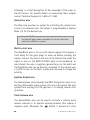
➜ System Maintenance
The system requires no specific maintenance. Your transmitter
is powered by a miniature 12-volt battery (type 23A) that will
last approximately one year under normal use. When the
battery begins to weaken, the operating range will be
reduced.
➜ FCC/Id Notice
This device complies with Part 15 of FCC rules. Operation is
subject to the following conditions: (1) This device may not
cause harmful interference, and (2) This device must accept
any interference received, including interference that may
cause undesirable operation.
Changes or modifications not expressly approved by the party
responsible for compliance could void the user's authority to
operate this device.
Warning! Safety First
The following safety warnings must be observed at all times:
When properly installed, this system can start the vehicle
via a command signal from the remote control transmitter. Therefore, never operate the system in an area
that does not have adequate ventilation. The following
precautions are the sole responsibility of the user;
however, the following recommendations should be made
to all users of this system:
1. Never operate the system in an enclosed or partially
enclosed area without ventilation (such as a garage).
© 2007 Directed Electronics
9
2. When parking in an enclosed or partially enclosed
area or when having the vehicle serviced, the remote
start system must be disabled by placing the system
into Valet Mode.
3. It is the user's sole responsibility to properly handle
and keep out of reach from children all remote control
units to assure that the system does not unintentionally remote start the vehicle.
4. The user must install a carbon monoxide detector in
or about the living area adjacent to the vehicle. All
doors leading from adjacent living areas to the
enclosed or partially enclosed vehicle storage area
must remain closed at all time.
Use of this product in a manner contrary to its intended mode of
operation may result in property damage, personal injury, or death.
Except when performing the Safety Check outlined in this user’s
guide, (1) Never remotely start the vehicle with the vehicle in gear,
and (2) Never remotely start the vehicle with the keys in the ignition.
After the remote start module has been installed, test the remote
start module in accordance with the Safety Check outlined in this
installation guide. If the vehicle starts when performing the
Neutral Safety Shutdown Circuit test, the remote start unit has not
been properly installed. The remote start module must be removed
or properly reinstalled so that the vehicle does not start in gear.
OPERATION OF THE REMOTE START MODULE IF THE VEHICLE STARTS
IN GEAR IS CONTRARY TO ITS INTENDED MODE OF OPERATION.
OPERATING THE REMOTE START SYSTEM UNDER THESE CONDITIONS
MAY RESULT IN PROPERTY DAMAGE OR PERSONAL INJURY. IMMEDIATELY CEASE THE USE OF THE UNIT AND REPAIR OR DISCONNECT THE
INSTALLED REMOTE START MODULE. DIRECTED WILL NOT BE HELD
RESPONSIBLE OR PAY FOR INSTALLATION OR REINSTALLATION
COSTS.
10
© 2007 Directed Electronics
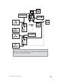
© 2007 Directed Electronics
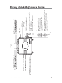
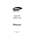
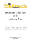
YELLOW/RED (-) lock or (+) unlock output
WHITE/RED (-) unlock or (+) lock output
SENSOR PORT
ANTENNA CABLE PORT
MOMENTARY SWITCH PORT
BLUE
PINK
GREEN (+) output to ign/acc2 circuit
Heavy Gauge
Wires
H1
H2
Black (-)
Heavy gauge
ground wire
GRAY/BLACK (-) Door trigger input
YELLOW/BROWN (-) 400mA Headlight output
BROWN (-) 400mA RAP, Dome light, Starter kill output
GREEN/WHITE (-) 400mA trunk release output
YELLOW/GREEN (+) ignition output
RED/BLACK (-) wait-to-start input
BLUE (-) 400mA horn/siren output
GREEN Tachometer input
RED/WHITE (-) remote start activation
WHITE/BLACK (-) 400mA status output
ORANGE (+) brake input
VIOLET (-) negative hood pin shutdown output
BROWN/WHITE (-) factory alarm disarm output
YELLOW (+/-) parking light output
Fused light
flash jumper
WHITE (+)
PINK
YELLOW
Wiring Quick Reference Guide
11
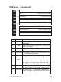
H1 Harness - 6 pin connector
H1/1
___ YELLOW
H1/2
___ BROWN/WHITE
H1/3
___ VIOLET
H1/4
___ ORANGE
H1/5
___ WHITE/BLACK
H1/6
___ RED/WHITE
(+/-) parking light output
(-) factory disarm output
(-) hood pin shutdown input
(+) brake switch shutdown input
(-) 400mA status output
(-) remote start activation input
Pin #
Color
Note
H1/1
Yellow
Selectable positive or negative parking light output
H1/2
Brown/White Use this wire if the vehicle is equipped with a
factory alarm. Connect to disarm wire listed on your
sheet.
H1/3
Violet
H1/4
Orange
H1/5
H1/6
12
Connect this wire to supplied hood pin switch
Connect this to wire in vehicle that shows 12 volts
when brake is pressed
White/Black Provides a ground during remote start. This wire is
normally connected to a bypass module if your
vehicle needs one.
Red/White This wire will start the vehicle when it sees two
negative pulses. Only used when incorporating into
existing alarm or for testing purposes.
© 2007 Directed Electronics
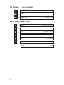
H2 Harness - 8 pin connector
H2/1
___ GREEN
H2/2
___ BLUE
H2/3
___ RED/BLACK
H2/4
___ YELLOW/GREEN
H2/5
___ GREEN/WHITE
H2/6
___ BROWN
H2/7
___ YELLOW/BROWN
H2/8
___ GRAY/BLACK
Pin #
Tachometer input
(-) 400mA horn/siren output
(-) wait-to-start input
(+) ignition output
(-) 400mA trunk release output
(-) 400mA RAP, Domelight, Starter Kill
(-) 400mA headlight output
(-) door trigger input
Note
H2/1
Color
Green
H2/2
Blue
H2/3
Red/Black
Negative output to horn or siren circuit. If your horn is
positive, use a relay.
Used on diesel engines only. Connects to wait-to-start
wire.
Use this wire if the vehicle fails to start correctly in
voltage mode.
H2/4 Yellow/Green Ignition output. Connect this wire to the ignition input
of an aftermarket alarm system.
H2/5
Green/White Trunk release wire. Connect this wire to trunk release
wire listed on your vehicle specific printout.
H2/6
Brown
Retained accessory shutdown or factory rearm output.
Connect this wire to factory arm wire if equipped, or to
door trigger wire if your vehicle’s accessories stay on
after remote start finishes cycle.
H2/7 Yellow/Brown Headlight output. Connect this wire to (-) headlight
wire in car. If headlights are positive, a relay is required.
H2/8
Gray/Black Door trigger input. This wire connects to the door trigger wire in your car to set off the alarm when system is
armed and door is opened.
© 2007 Directed Electronics
13
H3 harness - 3 pin connector
H3/1
___ YELLOW/RED
H3/2
___ EMPTY
H3/3
___ WHITE/RED
(-) lock/(+) unlock
(-) unlock/(+) lock
Relay Heavy Gauge Wires
1
___ GREEN
2
___ PINK
(+) 12 volt input
3
___ BLUE
(+) ignition 1 output
4
___ WHITE
5
___ PINK
(+) 12 volt input
6
___ YELLOW
(+) starter output
BLACK
14
(+) Ign2 or Acc2 output
(+) accessory output
(-) ground
© 2007 Directed Electronics
Installation Overview
Be sure to read this section thoroughly and view the Do-ItYourself Installation DVD video in its entirety before starting the
installation. Pay special attention to all warnings to prevent personal injury or damage to your vehicle.
Visit our 24-hour technical web site (www.readyremote.com) to
get a vehicle-specific wiring guide prior to starting this installation.
Have your crash code number handy when contacting tech support
or visiting the web site. During the installation if you are unable
to find answers to your questions on the web site, call 1-800-4771382 for live technical assistance. Please note that live technical
support is available Monday-Friday 6am-6pm PST, and SaturdaySunday 7am-3:30pm PST.
WARNING!
➤
➤
➤
Verify that the transmission is set to park and that
the parking brake is set before beginning installation.
On vehicles with air bags or supplemental restraint
systems (SRS) you may notice a bright yellow tube
with small wires in it, marked SRS, underneath the
steering column near the key cylinder. DO NOT tamper
or unplug these for any reason to prevent costly damages to your vehicle or personal injury. Tampering
may cause unintended deployment of airbags.
This system is intended for automatic, fuel-injected
vehicles only. Installation in any other vehicle is contrary to its intended use.
© 2007 Directed Electronics
15
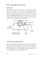
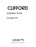
Step 1, Heavy Gauge Wire Connections
Ground Wire
The BLACK wire connects to the pin next to the light flash jumper
fuse. First strip back a ¾-inch section of the insulation off the
BLACK wire and crimp a ring terminal (not provided) to that wire.
Locate a clean, paint-free metal surface in the drivers kick panel
(DO NOT GROUND ON DASH). Using a self-tapping screw, drill the
screw with the ring terminal to the kick panel. Once screwed down,
pull on the wire to ensure a good connection.
SELF-TAPPING
BOLT OR SCREW
GROUND
WIRE
DIA-591
NOTE: REMOVE ANY PAINT
BELOW RING CONNECTOR
RING
TERMINAL
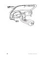
Constant Power and Ignition Wires
Almost all your power and ignition wires can be found behind the
key cylinder under the lower driver's side dash panel. Using the
appropriate hand tools, remove the lower dash panel taking care
not to break any parts. If the panel does not come off easily, check
for any additional screws you may have missed.
16
© 2007 Directed Electronics
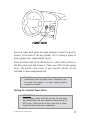
Once the lower dash panel has been removed, locate the ignition
harness at the back of the key cylinder. This is usually a group of
heavy gauge wires (approximate 14ga.).
Place the black lead of the LED tester to a clean metal surface in
the kick panel area and secure it. Probe one of the thicker gauge
wires. The ignition wire colors of your specific vehicle can be
obtained at www.readyremote.com.
Note! More problems are attributed to poor ground
connections than any other cause. Take extra care
to ensure the ground is a clean metal-to-metal
contact and secure.
Testing for Constant Power Wires
WARNING! Before making any connection to constant
battery power, make sure that the two 30 amp fuses
are removed from the fuse holders on the two pink 12
VOLT wires. Failure to do so may cause fire or shorting of sensitive electrical components.
© 2007 Directed Electronics
17
With the key in the off position, test the suspect wire. The
constant power wire will read 12V on the multimeter. Once the
constant power wire has been identified, solder the two heavy
gauge 12 VOLT wires (PINK) from the control module to it and
wrap the connection with electrical tape.
Note! If the vehicle has more than one constant
power wire, use two of them. Connect one of the
heavy gauge PINK wires to one of the constant
power wires, and the other heavy gauge PINK wire
to the other constant power wire.
Testing for Ignition Wires
With the multimeter lead still connected in the kick panel, locate
the suspected ignition wire. It will test differently than constant
12 volts. Place the red lead of the multimeter on the suspected
wire. With the key in the off position the multimeter will read 0.
Turn the key to the on position and the multimeter will read 12
volts. Now, watching your multimeter, turn the key to the crank
position. If the 12 volts stays on, then you have found your ignition wire. If the wire tests correctly, solder the BLUE heavy gauge
wire to it and wrap the connection with electrical tape.
If the vehicle requires more than one ignition as per the web site
information, follow the same test procedure and solder the GREEN
heavy gauge wire to it then wrap the connection with electrical
tape. If your vehicle has only one ignition wire, secure the GREEN
wire and dress it out of the way.
18
© 2007 Directed Electronics
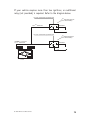
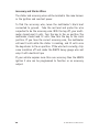
If your vehicle requires more than two ignitions, an additional
relay (not provided) is required. Refer to the diagram below.
+12 VDC CONSTANT (FUSED 20A)
2nd IGNITION RELAY
(NOT PROVIDED)
TO 2nd IGNITION
87
86
GROUND
87A
30
85
TO 2nd IGNITION
+12 VDC CONSTANT (FUSED 20A)
3rd IGNITION RELAY
(NOT PROVIDED)
GREEN (+) OUTPUT
TO 2nd IGNITION
87
86
87A
30
GROUND
85
TO 3rd IGNITION
© 2007 Directed Electronics
19
Accessory and Starter Wires
The starter and accessory wires will be located in the same harness
as the ignition and constant power.
To find the accessory wire, leave the multimeter’s black lead
connected to ground. Take the red lead and probe the wire
suspected to be the accessory wire. With the key off, your multimeter should read 0 volts. Turn the key to the on position The
multimeter should read 12 volts. Now turn the key to the crank
position. If you have the correct accessory wire, the multimeter
will read 0 volts while the starter is cranking, and 12 volts once
the key returns to the on position. If the wire tests correctly, strip
some insulation off and solder the WHITE heavy gauge wire and
wrap it with electrical tape.
If your vehicle requires more than one accessory then the GREEN
igniton 2 wire can be programmed to function as an accessory
output.
20
© 2007 Directed Electronics
If the GREEN wire is being used for Ignition 2, an additional relay
(not provided) is required for a 2nd accessory. Refer to the
diagram below.
+12 VDC CONSTANT (FUSED 20A)
ACCESSORY RELAY
(NOT PROVIDED)
87
TO ACCESSORY
86
GROUND
87A
30
85
TO ACCESSORY
+12 VDC CONSTANT (FUSED 20A)
2nd ACCESSORY RELAY
(NOT PROVIDED)
WHITE (+) 30A OUTPUT TO
ACCESSORY CIRCUIT
87
86
GROUND
87A
30
85
TO 2nd ACCESSORY
Now that the accessories have been located, find the suspected
starter wire according to the web information. Leave the black
lead of your tester on ground and place the red lead of your multimeter on this wire. The multimeter should read 0 volts in all key
positions except the crank position. In the crank position your
multimeter should read 12 volts, and will go to 0 volts when the
starter disengages.
© 2007 Directed Electronics
21
Many Nissan and Toyota vehicles have two starter wires. A relay
and/or resistor (not provided) is required to hook up the additional starter wire. Refer to the diagram below.
+12 VDC CONSTANT (FUSED 20A)
STARTER RELAY
(NOT PROVIDED)
87
TO STARTER
86
GROUND
87A
30
85
TO STARTER
+12 VDC CONSTANT (FUSED 20A)
2nd STARTER RELAY
(NOT PROVIDED)
YELLOW (+) OUTPUT
TO STARTER
87
86
GROUND
87A
30
85
TO 2nd STARTER
Note! Always check the Web site information
on your vehicle for warnings regarding the
starter wire and check engine lights. Some
vehicles will trip a check engine light if the
starter wire is cut.
Once you locate the starter wire, cut the wire in half (check the
web information before cutting) and try to start the vehicle. If
the vehicle does not start, the correct wire has been identified.
Reconnect both ends of the starter wire while soldering the thick
YELLOW (6) wire of the heavy guage wires to it and wrap the
connection with electrical tape.
22
© 2007 Directed Electronics
Step 2, H1, Main Harness Connections
Factory Alarm Disarm
Since many newer vehicles come equipped with a factory alarm, it
is necessary to disarm it when unlocking the doors or during
remote start. Do not mistake a factory alarm with an immobilizer
system. They each require different disarm operations.
Locate the factory alarm disarm wire using the web site information. Once the suspect wire is located, place the multi-meter's red
lead to a (+)12 volt constant source and secure it. Put the multimeter in the DC position. Then probe the suspect wire with the
black lead of your meter. While probing the wire, place the key in
the driver's door cylinder. Turn it to the unlock position and hold
it when testing for the disarm wire. The multimeter should read
12V and will go back to 0V when the key is released.
When the correct wire has been found, solder the BROWN/WHITE
wire of the 6-pin harness to the wire that you determined to be
the factory alarm disarm wire. After this wire has been connected,
wrap the connection with electrical tape.
Note! On some vehicles the Factory Alarm Disarm
wire is connected to a Body Control Module or a Door
Module. If you find this configuration, please call
Technical Support at 1-800-477-1382.
Note! Some vehicles use a (+) trigger factory alarm
system. Use the website to determine if your vehicle
has a (+) trigger. If your vehicle has such a system,
call 1-800-477-1382 for live technical assistance, as
special wiring and an additional relay is required.
© 2007 Directed Electronics
23
Parking Light Flash
There are several different types of parking light circuits. The
following description is for a standard positive-triggered parkinglight circuit only. If the web vehicle information suggests a (-)
parking light circuit, the fuse jumper (on the side of the module)
must be moved to the opposite position.
A red 10 amp mini-fuse is included in a small plastic bag inside
the packaging. THIS FUSE MUST BE INSERTED FOR THE PARKING
LIGHTS TO WORK!
Using the web information on the vehicle, locate the suspected
wire. Connect the black multimeter lead to ground in the kick
panel. Probe the suspected wire with the red lead of your meter.
With the switch in the off position the multimeter should read 0
volts. While watching the multimeter, turn your headlight switch
to the parking light position. The multimeter should read 12 volts.
While testing the suspected wire, run the dash dimmer light
control up and down. The voltage should NOT vary. If the voltage
does vary, then this is the wrong wire. Continue probing to find
the correct wire.
Once you have identified the correct wire, solder the small YELLOW
wire of the 6-pin harness to it and wrap the connection with electrical tape. If your light circuit tests the opposite position, you
most likely have a (-) parking light circuit.
Important! Remember this description is for a (+)
parking light circuit. A (-) circuit will test differently.
Also, if the web information requires using resistors
for parking lights, contact Technical Support.
24
© 2007 Directed Electronics
Safety Shutdown Wires
With all ignition wires properly connected, find the appropriate
safety shutdown wires. These are the brake wire and hood pin
wires.
WARNING! These wires are meant to protect the
vehicle and anyone near the vehicle. They MUST
be connected to prevent damage to the vehicle
and possible bodily injury.
First locate the factory brake wire using your multimeter. Find the
switch at the top of the metal arm coming off the brake pedal. Use
your vehicle specific wiring information to determine the color of
this wire. With the black lead of your multimeter still in the kick
panel, probe the suspected wire with the red lead of your multimeter.
With the brake pedal at reset, the multimeter should read 0 volts.
While watching the multimeter, depress the brake pedal. The
multimeter should read 12 volts. Once you have located the
correct brake wire, solder the small ORANGE wire in the 6-pin
harness to it and wrap the connection with electrical tape.
WARNING! Do not use the vehicle until you
confirm the operation of the brake shutdown.
Installing the hood pin switch requires drilling a hole in a metal
lip under the hood. Choose a location that will allow the pin
switch to be completely depressed when the hood is closed. The
pin switch has a spade connector on the bottom for the wire
connection.
WARNING! Wear eye protection when drilling.
© 2007 Directed Electronics
25
Crimp your spade connector to the hood pin wire, and run the wire
into the vehicle's passenger compartment through a factory rubber
grommet (at the same time you might want to run the Tachometer
Input wire and Horn output wire from the Optional Harness
through the fire wall as you may need to connect them using the
following steps).
Using a sharp, pointed object, poke a hole into the grommet
(being careful not to damage any existing wires in the grommet)
and attach the wire to the object with electrical tape. Pull the
wire through the grommet, taking extra care to keep the wire away
from any moving parts or anything that will generate extreme
heat.
An alternative to this method would be to find a spot on the firewall with sufficient clearance on both sides and drill an access
hole through the firewall. Take note of what is directly on the
other side of where you are drilling as to not puncture brake cylinders, computers, etc. Once the wire is run into the vehicle and
secured from any moving parts, solder the wire to the VIOLET wire
of the 6-pin harness and wrap the connection with electrical tape.
WARNING! This wire MUST be connected. Do not
use the vehicle until you confirm the operation
of the hood pin shutdown. Improper operation
could result in serious injury or death.
26
© 2007 Directed Electronics
Step 3, H3 Door Lock Connections
There are eight different types of door lock systems (Type A - H).
Refer to the vehicle-specific wiring instructions on the web and
the chart below to help determine which door lock system your
vehicle uses. On some late model GM vehicles a door lock data
interface module may be required.
Type A: Three-wire (+) pulse controlling factory lock relays.
Type B: Three-wire (-) pulse controlling factory lock relays.
Note! From the factory, your system is set up for Type
B (-) door locks. To change your door lock outputs to
Type A (+), simply use the wires in the opposite configuration. You will now have (+) door locks.
Type C: Direct-wired reversing-polarity switches. The switches are
wired directly to the motors. This type of system has no factory
relays. Relays (not included) will be required for this type of door
lock system.
Type D: Adding one or more aftermarket actuators. These include
slave systems without an actuator in the driver's door, but with
factory actuators in all the other doors.
Type E: Electrically-activated vacuum systems.
Type F: One-wire system - cut to lock, ground to unlock.
This is a very rare system found mainly in early 90's imports
Type G: Positive (+) multiplex. One wire controls lock and unlock
using resistor(s).
Type H: Negative (-) multiplex. Same as type G system, but uses
(-) pulse instead.
© 2007 Directed Electronics
27
All other door lock systems will require additional relays and/or
resistors. A Directed Electronics 451M Doorlock module can be
used for these other applications. The 451M also includes diagrams and resistors required for most applications.
28
© 2007 Directed Electronics
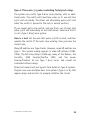
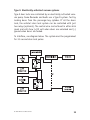
Type A: Three-wire (+) pulse controlling factory lock relays
The system can control Type A door locks directly, with no additional parts. The switch will have three wires on it; one will test
(+)12 volt constantly. The others will alternately pulse (+)12 volt
when the switch is pressed to the lock or unlock position.
If you cannot get to the switch, and you find a set of wires that
pulse (+)12 volt alternately on lock and unlock, make sure that it
is not a Type C direct-wire system.
Here is a test: Cut the wire that pulses (+)12V on lock, and then
operate the switch. If the locks stop working, then you have the
correct wire.
Many GM vehicles use Type A locks. However, some GM vehicles are
Type C. This system usually appears in older GM vehicles (19801995). The full-size pickups (1989-up), many of the Blazers, the
Corvette, 1995 Cavalier/Sunfire 1993, and the newer
Camaro/Firebird, all use Type C door locks, and cannot be
controlled without relays.
Almost all newer Fords are Type B. Ford builds no Type A systems.
Chrysler now uses multiplex door lock systems (Type G or H) that
require relays and resistors to properly interface the circuit.
© 2007 Directed Electronics
29
Important: Remember that these wires’ functions reverse between
Type A and Type B.
30
© 2007 Directed Electronics
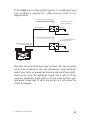
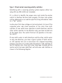
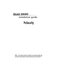
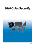
Type B: Three-wire (-) pulse controlling factory lock relays
This system is common in many Toyotas, Nissans, Hondas, Saturns,
and almost all newer Fords with keyless entry systems. Use your
vehicle sprcific wiring information to locate this wire. If you cut
the wire and the locks stop working, then you are on the correct
wire.
POWER DOOR
LOCK SWITCH
LOCK
(-) CHASSIS
GROUND
UNLOCK
(-)
LOCK OUTPUT
(-)
UNLOCK OUTPUT
FACTORY RELAYS
Note: If your locks operate in the reverse, (lock when
pressing unlock, and unlock when pressing lock) then
switch the lock/unlock wires and the locks will operate
correctly.
© 2007 Directed Electronics
31
Type C: Direct-wired reversing polarity switches
Interfacing with a reversing polarity system requires either two
relays OR one DEI 451M (not included).
It is critical to identify the proper wires and locate the master
switch to interface the door locks properly. This door lock system
will be referenced on our vehicle specific wiring information sheet
as a "5wi" system.
Locate wires that show voltage on lock and unlock. Cut one of the
suspected wires and check operation of the locks from both
switches. If one switch loses operation in both directions and the
other switch operates in one direction only, you have located one
of the target wires. The switch that lost all operation is the master switch.
If one switch works in both directions and the other switch works
in only one direction, you have a Type A system. If both switches still operate, but one or more doors has stopped responding
entirely, you have cut a motor lead. Reconnect it and continue to
test for another wire. Once both wires have been located and the
master switch has been identified, cut both wires and interface as
shown in the following diagram.
32
© 2007 Directed Electronics
Caution: If these wires are not connected properly, you will
send (+) 12 volts directly to (-) ground, possibly damaging
the alarm or the factory switch.
© 2007 Directed Electronics
33
Type D: Adding one or more aftermarket actuators
In order for this system to control one or more aftermarket actuators, a DEI 451M (not included) or two relays are required.
Vehicles without factory power door locks require the installation
of one actuator per door. This requires mounting the door lock
actuator inside the door.
Other vehicles may only require one actuator installed in the driver's door, if all door locks are operated when the driver's lock is
used. This type of installation is required to operate factory lock
systems in Volvo (except 850), SAAB, and most Kia, Mazda, Isuzu
and Subaru models. The fuse used on 12 volt inputs should be
7.5A per motor installed in the vehicle.
Important! Do not connect the outputs of the alarm directly
to the actuator.
Note: Directed Electronics offers actuators available at larger retail
chain stores. You will find them in the installation bay (P/N:524T).
34
© 2007 Directed Electronics
Type E: Electrically-activated vacuum systems
Type E door locks are controlled by an electrically activated vacuum pump. Some Mercedes and Audis use a Type D system. Test by
locking doors from the passenger key cylinder. If all the doors
lock, the vehicle's door lock system can be controlled with just
two relays (optional). The control wire can be found in either kick
panel and will show (+)12 volt when doors are unlocked and (-)
ground when doors are locked.
To interface, see diagram below. The system must be programmed
for 3.5 second door lock pulses.
© 2007 Directed Electronics
35
Type F: One-wire system - cut to lock, ground to unlock
Type F door locks usually require a negative pulse to unlock and
cutting the wire to lock the door. In some vehicles, these functions are reversed. Type F door locks are found in late-model
Hyundai, Nissan Sentras, some Nissan 240SX, and Nissan 300ZX
1992-up. They are also found in some Mazda MPV's and some
Mitsubishi's.
One relay (not included) is used to interface to this type of
system as follows:
36
© 2007 Directed Electronics
Type G: Positive (+) multiplex
This system is sometimes found in Ford, Mazda, Chrysler, and GM
vehicles. The door lock switch or door key cylinder may contain
either one or two resistors. When interfacing with this type of
door lock system, two relays or a DEI 451M must be used.
Single-Resistor Type
If one resistor is used in the door lock switch/key cylinder, the
wire will pulse (+)12 volt in one direction and less than (+)12 volt
when operated in the opposite direction.
Two-Resistor Type
If two resistors are used in the factory door lock switch/key cylinder, the switch/key cylinder will read less than (+)12 volt in both
directions.
© 2007 Directed Electronics
37
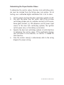
Determining the Proper Resistor Values
To determine the resistor values, the door lock switch/key cylinder must be isolated from the factory door lock system. For all
testing, use a calibrated digital multimeter that is set to ohms.
1.
2.
3.
4.
38
Cut the output wire from the door switch/key cylinder in half.
Test with the meter from the switch side of the cut door
switch/key cylinder wire to a reliable constant (+)12V source.
Some good constant (+) 12V references are the power input
source to the door lock switch/key cylinder, the ignition
switch power wire, or the battery (+) terminal.
Operate the door lock switch/key cylinder in both directions
to determine the resistor values. If the multimeter displays
zero resistance in one direction, no resistor is needed for
that direction.
Once the resistor value(s) is determined, refer to the wiring
diagram for proper wiring.
© 2007 Directed Electronics
Type H: Negative (-) multiplex
The system is most commonly found in Chryslers and a few latemodel GM vehicles. The door lock switch or door key cylinder may
contain either one or two resistors.
Single-Resistor Type
If one resistor is used in the door lock switch/key cylinder, the
wire will pulse ground in one direction and resistance to ground
when operated in the opposite direction.
Two-Resistor Type
If two resistors are used in the factory door lock switch/key
cylinder, the door lock switch/key cylinder will read resistance to
ground in both directions.
© 2007 Directed Electronics
39
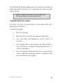
Determining the Proper Resistor Values
To determine the resistor values, the door lock switch/key cylinder must be isolated from the factory door lock system. For all
testing, use a calibrated digital multimeter that is set to ohms.
1.
2.
3.
4.
40
Cut the output wire from the door switch/key cyclinder in
half.
Test with the meter from the switch side of the cut door
switch/key cylinder wire to a reliable constant (+)12V source.
Some good constant (+) 12V references are the power input
source to the door lock switch/key cylinder, the ignition
switch power wire, or the (+) terminal battery.
Operate the door lock switch/key cylinder in both directions
to determine the resistor values. If the multimeter displays
zero resistance in one direction, no resistor is needed for
that direction.
Once the resistor value(s) is determined, refer to the wiring
diagram for proper wiring.
© 2007 Directed Electronics
Step 4, H2 Harness
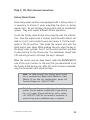
Engine Monitoring Explained
During remote start, the system needs to know if the engine is
running. The module does this by monitoring the voltage of the
vehicle's electrical system (or the tachometer: see next section).
Voltage Monitoring
Note! If the system has been programmed for
Tachometer monitoring previously, it must be
reprogrammed to Voltage monitoring.
Vehicle electrical systems usually rest at about 12.6 volts when
the engine is not running. This system is programmed to detect
the rise in battery voltage that occurs when the charging circuit
activates after starting, and keep the engine running if the rise is
adequate. It will make up to three start attempts before discontinuing due to an inadequate voltage rise.
Some vehicles have alternators that do not activate immediately
or do not increase voltage sufficiently after starting. This system
will compensate by delaying the time before reading the battery
voltage on the second and third start attempts. This delay will
allow most alternators to activate so the remote start will
continue to run.
The voltage read times are:
First attempt: 10 seconds
Second attempt: 20 seconds
Third attempt: 50 seconds
After the third start attempt, if the voltage increase is still not
adequate to keep the engine running, the Tachometer input
option should be used to monitor the engine.
© 2007 Directed Electronics
41
Tachometer Wire
WARNING! In the following procedure DO NOT use
a test light. Use of this type of tester can cause
grounding of sensitive electrical components,
resulting in damage, including damage to the power
train control module. A digital multi-meter is
required to test for this wire.
Do not wear loose clothing that could get entangled
in rotating engine components. Ensure that your
hands and arms are well clear of these rotating
components when working in the engine compartment. Lastly, ensure that all wires and tools are
clear of falling into or entanglement with these
rotating components.
Identify the suspected tach wire according to the web information. Next, place the black lead of a MULTI-METER on the negative battery post and secure it. Put the multi-meter in the AC position and connect the probe to the suspect wire with the red lead
of the multi-meter. Then start the vehicle with the key. With the
engine at idle the multi-meter should read from .50 volts to 6
volts, and should fluctuate when you rev the engine.
Have a second person press the gas pedal to increase the RPMs
and watch the meter display. When the RPMs increase the voltage
should rise slightly (not all tachometer outputs will rise when
engine RPM increases). Once the correct tachometer wire has been
identified, turn the vehicle off.
Run the GREEN wire from the 8-pin harness through the firewall
into the engine compartment alongside the hood pin wire. Use the
same procedure as with the hood pin wire and pull the wire
through the grommet, taking extra care to keep it away from any
moving parts or anything that will generate extreme heat. Once
the wire is run into the engine compartment, strip a small portion
42
© 2007 Directed Electronics
of insulation off the tachometer wire in the vehicle and solder the
green tachometer input wire to it. Then wrap the connection with
electrical tape.
Note! If using a tach signal, the tach signal MUST
be learned before using the remote starter.
LEARNING YOUR TACH SIGNAL
If using a tach wire, you must learn the tach signal after completing the installation.
To learn tach signal:
1.
Start car with key.
2.
Wait about 5 seconds for the engine to idle down.
3.
Press and hold the Momentary switch (about 10
seconds).
4.
Tach learned: After a few seconds the LED will flash 2
times and turn on. Continue to hold the switch for 2 - 3
seconds and release.
5.
Tach not learned: The LED will not turn on and will flash
3 times when the momentary switch is released. Check
the connections and try again.
© 2007 Directed Electronics
43
Following is a brief description of the remainder of the wires in
the H2 harness. For specific details on connecting these outputs
contact Technical Support at 1-800-477-1382.
Horn/siren wire
The Blue wire provides an output for activating the vehicle horn
circuit or an external siren. The output is programmable in Feature
Menu 1/9 for the desired use.
Important! This is a low current output which requires
an external relay when connected to circuits that draw
more than 400mA in current.
Wait-to-start wire
The Red/Black wire is for use with diesel engines that require a
short delay for the glow plugs to warm up before cranking the
engine. Connect this wire to the wire in the vehicle that sends the
signal to turn on the WAIT-TO-START bulb in the dashboard. In
most diesels the wire is negative (ground turns on the bulb) and
the Red/Black wire can be directly connected. If the vehicle uses
a (+)12V to turn on the bulb, a relay must be used to change the
polarity.
Ignition Output wire
The Yellow/Green wire should be the ONLY the ignition input to an
existing aftermarket alarm system. This wire will prevent the host
system from sensing that the ignition is on during remote start
operation.
Trunk Release wire
The Green/White wire can be used to activate a vehicle trunk
release solenoid or to operate optional modules that require a
negative input. Whenever the
button is pressed for a few
44
© 2007 Directed Electronics
seconds the system will disarm/unlock and then activate this
output. The output will then remain on until the transmitter
button is released.
Important! This is a low current output which
requires an external relay when connected to circuits that draw more than 400mA in current.
Retained Accessory, Dome Light or Starter Kill wire
The Brown wire has three optional uses, depending on the vehicle
application and user preference. The three available operations are
programmable in Feature Menu 2/11.
➤ RAP or Retained Accessory Power: This option is
designed to turn off accessories that remain on after the
ignition is turned off. It will pulse 10 seconds after the
remote start status output ceases. It will cause the
vehicle body control module to “think” the door has
opened, thus turning the accessories off.
➤ Dome Light Supervision: This option will turn on the
dome light for 25 seconds each time the vehicle is
unlocked. It will cease if the doors are locked or the
ignition is turned on.
➤ Starter Kill/Anti-grind: This option activates when the
doors are locked to allow for starter kill for the alarm
system, and also works as an anti-grind when the
remote start is active.
Important! This is a low current output which
requires an external relay when connected to circuits that draw more than 400mA in current.
© 2007 Directed Electronics
45
Headlight Control wire
The Yellow/Brown wire provides an output for activating the
vehicle headlight circuit. It is controlled by both the ignition
switch and the transmitter. It is programmable in Feature Menu
1/10 for the type of ignition controlled activation.
Important! This is a low current output which
requires an external relay when connected to circuits that draw more than 400mA in current.
Door Trigger wire
The Gray/Black wire will trigger the alarm and is designed to be
connected to the door switch that turns on the dome light when
the door is opened. It is a negative input circuit only. If your
vehicle uses a positive door switch circuit, call for assistance in
making the connection.
46
© 2007 Directed Electronics
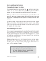
Step 5, Mounting the Receiver/Antenna
Receiver/antenna position should be discussed with the vehicle
owner prior to installation, since the antenna may be visible to
the vehicle’s operator.
The best location for the receiver/antenna is centered high on
either the front or rear windshield. For optimal range, the antenna should be mounted vertically. It can be mounted horizontally
in relation to the windshield or under the dashboard away from
metal, but range will be diminished. Window tint or dot matrix
(small black dots at top of windshield) can also affect range, so
this should be a consideration when determining the mounting
location.
After determining the best mounting location, follow these steps:
1.
Clean the mounting area with a quality glass cleaner or
alcohol to remove any dirt or residue.
2.
Plug the receiver/antenna cable into the
receiver/antenna.
3.
Mount the receiver/antenna using the supplied doublesided tape.
4.
Route the receiver/antenna cable to the control module
and plug it into the four-pin antenna connector.
Important! To achieve the best possible range,
DO NOT leave the antenna cable bundled under
the dash. Always extend the cable full length during installation, regardless of the antenna mounting location.
© 2007 Directed Electronics
47
48
© 2007 Directed Electronics
Step 6, Immobilizer Bypass Modules
Most newer vehicles have a factory engine immobilizer system
designed to prevent any unauthorized use of the vehicle. These
immobilizers will cut off power to the starter and the fuel supply
preventing a thief from starting the vehicle.
There are several types of immobilizers, with the most common
being the resistance-based Passlock/Passlock 2 systems found on
most newer GM vehicles. This system can be bypassed using the
20402, 29402 or 556L immobilizer bypass modules available at
your local authorized retailer or at www.directedstore.com. The
majority of transponder-based immobilizer systems can be
bypassed using the 20402, 29402 or 556U immobilizer bypass
module available at your local authorized retailer.
The WHITE/BLACK wire of the 6-pin harness supplies a 400mA (-)
output as soon as the control module begins the remote start
process. This wire can be used to activate an immobilizer bypass
unit.
Note! Any vehicle equipped with a factory immobilizer must use an immobilizer bypass module to
remote start. If not used, the vehicle ignition or
fuel supply circuits could lock up and require a
costly trip to the dealer to reset the computer system.
To determine which bypass module your vehicle requires, use the
website Interface Module Look-Up tool at www.readyremote.com.
© 2007 Directed Electronics
49
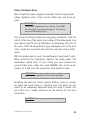
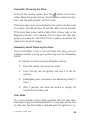
Step 7, Programming
Programming transmitters
Your system can learn up to 4 transmitters. The following procedure will show you how to add additional transmitters or replace
old ones. The remotes in this package have already been
programmed to the control module.
Each transmitter can be programmed one button at a time or you
can use an auto learn procedure that learns the intended factory
configuration. Learning one button at a time is generally only
used when using one transmitter to control two different cars.
Being able to program functions to different channels on each
transmitters prevents multiple cars from responding simultaneously.
1.
Turn the ignition ON
2.
Press/release the Momentary switch the same number of
times as the desired transmitter learn step number, and
then Press/HOLD.
3.
After holding the Momentary switch for 2 seconds the
LED will begin to flash to indicate the number of the
accessed transmitter learn step.
4.
Press the transmitter button that you want to control
the function assigned to that channel. The Horn/Siren
will emit a long chirp.
Note: For transmitter learn Step #1, you must press the “*” button on the transmitter. This will automatically program the transmitter buttons to the default function configuration. See the
transmitter button auto learn chart for the assignment functions.
50
© 2007 Directed Electronics
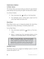
You can learn more than one transmitter function without having
to repeat the entire procedure by advancing to the next channel
immediately after programming your first channel.
To do this, first release the Momentary switch and then
press/release it the same number of times as the difference
between the current transmitter learn Step and the desired transmitter learn Step, and then press/HOLD it.
Example: To advance from Transmitter Learn
Step 2 to Transmitter Learn Step 8, release the
Momentary switch and then press/release it 6
times and HOLD it on the 7th press.
After holding the Valet switch for 2 seconds the LED will flash 8
times and repeat. You can now learn a transmitter button to step
8.
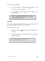
There are several ways to exit Transmitter Learning, by TimeOut,
Ignition or Momentary switch presses.
1.
TimeOut: If more than 15 seconds elapse between
Momentary switch presses or transmitter signals.
2.
Ignition: If the Ignition is turned off at any time during
transmitter Learning.
3.
Momentary switch presses: if you press/release the
Momentary switch more times than there are Transmitter
Learning steps in the menu.
The Horn output will pulse 5 times rapidly and the LED will turn
off to indicate that you are exiting feature programming.
© 2007 Directed Electronics
51
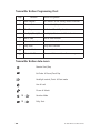
Transmitter Button Programming Chart
Step
Function
Button Assignment
1
Auto-Program
ALL buttons to the factory default functions
2
Remote Start
Remote Start/Stop function
3
Trunk Pop
Carfinder & Trunk Pop functions
4
Headlight/Panic/Silent Headlight, Silent mode & Panic functions
5
Arm & Lock
Arm & Lock function
6
Disarm & Unlock
Disarm & Unlock functions
7
Daily Start
Daily Start function
8
Vacation Mode
Vacation Start function
9
Delete ALL TXs
Removes ALL transmitters from memory
Transmitter Button Auto-Learn
Remote Start/Stop
CarFinder & Disarm/Trunk Pop
Headlight control, Panic & Silent mode
Arm & Lock
Disarm & Unlock
52
&
Vacation Mode
&
Daily Start
© 2007 Directed Electronics
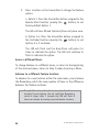
Programming System Settings
Many of the features and operations of this system can be changed
to suit most of today's vehicle electrical systems. The programming routine and feature menus that follow will allow making the
changes required for most vehicle installations.
System programming routine:
Accessing a Menu:
1.
Turn the ignition ON and then OFF in less than 5 seconds
2.
Within 3 seconds, Press/Hold the Momentary switch
3.
After 2 seconds, the LED will flash and the Horn/Siren
will pulse to indicate the available menus. It will toggle
through the outputs until a menu is chosen.
a. Menu 1: 1 LED flash and 1 Horn/Siren pulse
b. Menu 2: 2 LED flashes and 2 Horn/Siren pulses
4.
Release the Momentary switch after the appropriate
output in order to access that Menu. The LED and
Horn/Siren outputs will cease.
Accessing a Feature Location:
1.
Press and release (do not hold) the Momentary switch
the same number of times as the feature location to be
accessed. See the Feature Chart for locations.
2.
After 2 seconds the LED will flash (the number of flashes
will match with the feature location) to confirm the
feature location. It will flash/pause and repeat until the
feature is changed or programming is exited.
© 2007 Directed Electronics
53
3.
Press a button on the transmitter to change the feature
option:
a. Option 1: Press the transmitter button assigned to the
Remote Start function (usually the
button) to set
factory default Option 1.
The LED will turn ON and the Horn/Siren will pulse once.
b. Option 2-4: Press the transmitter button assigned to
the CarFinder function (usually the
button) to set
Options 2-4 if available.
The LED will flash and the Horn/Siren will pulse 2-4
times to indicate the option. The LED will continue to
flash to indicate the option.
Access a different Menu:
To change features in a different menu, or return to the beginning
of the accessed menu, return to Step 2 under Accessing a Menu.
Advance to a different feature location:
To advance to a new location within the same menu press/release
the Momentary switch the same number of times as the difference
between the feature locations.
Example! To advance from feature location 2 to feature
location 8 press/release (do not hold) the Momentary
switch 6 times, after 2 seconds the LED will flash 8
times to indicate the newly accessed feature location.
54
© 2007 Directed Electronics
Exiting Feature programming:
The following will cause the system to exit programming and is
indicated by 5 short chirps of the Horn/Siren output.
a. More than 15 seconds lapses between inputs by
Momentary switch or transmitter button
b. The ignition is turned on
Feature Menus
Feature Menu 1 Chart
Feature
Location
Feature Name
Option 1
(Default)
Option 2
Option 3
Option 4
1
Engine Monitoring
No Tach
Tach
NA
NA
2
Run Time
15 min
30 min
NA
NA
3
Crank time
Normal
ExtraCrank
Super crank
Mega crank
4
Ign2 Output
Ign 2
ACC 2
NA
NA
5
Wait-to-start
Diesel Input
wire
Diesel Timer
NA
NA
6
Activation Input
2 pulse
1 pulse
NA
NA
7
Vacation Temp
0 degrees F
-10 degrees F
-20 degrees F
NA
8
Alarm Disarm
1 second
450 ms
NA
NA
9
Horn Output
NA
NA
10
Headlights
Daytime
Light your
way
NA
NA
11
Start Chirp
On
Off
NA
NA
12
NA
NA
NA
NA
NA
13
Horn/Pulsing Siren/Constant
Reset All Options
© 2007 Directed Electronics
Press ANY TRANSMITTER button to reset all
features
55
Feature Menu 1 Descriptions
1. Engine Monitoring: Defines how the engine is monitored while
the Remote Start is active.
1. No Tach: The battery voltage will be used to monitor the
engine while Remote Start is active.
2. Tachometer: The tachometer will be used to monitor
engine speed while Remote Start is active.
2. Run Time
1.
15 minutes: The Remote Starter will shut down after it
has been active for 15 minutes.
2.
30 minutes: The Remote Starter will shut down after it
has been active for 30 minutes.
3. Crank Time: Will be in effect only when Engine Monitoring is
"No Tach" and affects the duration of the "Yellow" Starter Output
wire.
1.
Normal Crank: The Starter output will be 700mS.
2.
Extra Crank: The Starter output will be 1 second.
3.
Super Crank: The Starter output will be 1.4 seconds.
4.
Mega Crank: The Starter output will be 2.1 seconds.
4. Ignition 2 Output: This controls the output type of the high
current "Green" Ignition 2 output wire.
56
1.
Ignition 2: Output will match the Blue Ignition 1
input/output wire operation during remote start.
2.
Accessory 2: Output will match the White Accessory 1
operation during remote start.
© 2007 Directed Electronics
5. Wait-To-Start: This chooses the method of Starter output delay
for Diesel engines.
1.
Diesel Input wire: An input on the "Red/Blk" wire will
delay the Start output until the input ceases.
2.
Diesel Timer: The Starter output will be delayed until
the timer expires. The "Red/Blk" wire will be ignored.
6. Activation Input: Selects the number of inputs from the transmitter or the "Red/Wht" activation input wire to activate the
Remote Starter.
1.
2 Pulses: Two input pulse will Start and Stop the
Remote Starter
2.
1 Pulse: One input pulse will Start and Stop the Remote
Starter
7. Vacation Temp: Selects the temperature threshold that will activate the Remote Starter when Vacation Mode has been activated.
1. 0 Degrees F
2. -10 Degrees F
3. -20 Degrees F
8. Alarm Disarm: Selects the output duration of the "Brown/Wht"
Factory Alarm Disarm wire.
1. 1 second: The output will be 1 second in duration
2. 0.45 second: The output will be 0.45 sec. in duration
9. Horn Output: Selects the type of output on the "Blue" Horn
output wire when the alarm is fully triggered but does not affect
the arm/disarm/remote start/programming chirp outputs.
1. Horn: The output will be pulsed during full trigger events
© 2007 Directed Electronics
57
2. Siren: The output will be constant during full trigger
events.
10. Headlights: Selects the operation of the "Yellow/Brn" headlight output wire when an ignition input is sensed.
1.
Daytime Running: The output will activate 10 seconds
after an ignition input is sensed and cease output 1
second after the ignition input ceases.
2.
LightYourWay: The output will activate for 25 seconds
immediately after the ignition input ceases.
11. Start Chirps: Selects if the "Blue" Horn/Siren output wire will
pulse when activating Remote Starter.
1.
On: The Horn output will pulse 1 time at the beginning
of Remote Start
2.
Off: The Horn output WILL NOT pulse at the beginning
of Remote Start
12. Not applicable.
13. Reset All Options: Pressing a transmitter button when this
Feature Location is accessed will "Reset All Options" in both
menus to their default setting.
58
© 2007 Directed Electronics
Feature Menu 2 Chart
Feature
Location
Feature Name
Option 1
(Default)
Option 2
Option 3
1
Arming Type
Active
Passive
NA
2
Locking Type
Active
Passive
NA
3
Ignition Locking
OFF
Lock w/Ign On
/ Brake
NA
4
Ignition Unlocking
OFF
Unlock w/Ign
OFF
NA
5
Lock Pulses
1
2
NA
6
Unlock Pulses
1
2
NA
7
Lock Duration
Short 0.8
seconds
Long 3.5
seconds
NA
8
Alarm Mode
OFF
ON
NA
9
Auto Rearming
OFF
ON
NA
10
Alarm Chirps
OFF
ON
NA
11
ACC
Pulses/Domelight/St
arter kill
Accessory
Pulse (RAP)
Domelight
Starter
Kill/Antigrind
Output
Feature Menu 2 Descriptions
1. Arming Type: Selects if the alarm will arm by one or both available methods.
1.
Active: The alarm will arm via transmitter only
2.
Passive: The alarm will arm via transmitter and Passive
Arming criteria.
© 2007 Directed Electronics
59
2. Locking Type: Selects the type of arming operations that activate the door locks.
1.
Active: The doors will lock when armed via transmitter
and Auto Re-arming.
2.
Passive: The doors will lock when armed via transmitter,
Passive Arming and Auto Re-arming.
3. Ignition Locking: Selects if the door locks will activate after an
ignition input is sensed.
1.
Off: The Door Lock output will not activate due to an
ignition input sense.
2.
On: The Door Lock output will activate when the brake
input and an ignition input is sensed.
4. Ignition Unlocking: Selects if the door locks will activate after
the ignition input ceases.
1.
Off: The Door Unlock output will not activate when the
ignition input ceases.
2.
On: The Door Unlock output will activate 100mS after
the ignition is turned off.
5. Lock Pulses: Selects the number of pulses when locking the
doors.
60
1.
1 Pulse: The Door Lock output will be one pulse for the
programmed duration.
2.
2 Pulses: The Door Lock output will be 2 pulses for the
programmed duration.
© 2007 Directed Electronics
6. Unlock Pulses: Selects the number of pulses when Unlocking the
doors.
1.
1 Pulse: The Door Unlock output will be a single pulse
for the programmed duration.
2.
2 Pulses: The Door Unlock output will be a double pulse
for the programmed duration.
7. Lock Duration: Selects the duration of the pulses when Locking
and Unlocking the doors.
1.
Short Pulse: The Door Lock & Unlock outputs will be
800mS in duration.
2.
Long Pulse: The Door Lock & Unlock outputs will be a
3.5 seconds in duration.
8. Alarm Mode: Selects if the alarm functions are active or
bypassed.
1.
On: Alarm functions are operational as described
2.
Off: Alarm functions are NOT operational, but convenience features and Remote Starter still operate
normally.
9. Auto Re-arming: Selects if the units will automatically Rearm/lock itself if the trunk and door are not activated after transmitter disarm/unlock.
1.
Off: The unit WILL NOT automatically Arm/Lock the
doors after transmitter Disarm/Unlock.
2.
On: The unit will automatically Arm/Lock the doors 120
seconds after transmitter Disarm/Unlock if Alarm Inputs
1 or 6 remain idle.
© 2007 Directed Electronics
61
10. Alarm Chirps: Selects if the "Blue" Horn output wire will pulse
when Arm/Lock and Disarm/Unlock are activated.
1.
On: The Horn output will pulse 1 time for Arm/Lock and
2 times for Disarm/Unlock.
2.
Off: The Horn output WILL NOT pulse for Arm/Lock or
Disarm/Unlock.
11. Acc pulse/DomeLight/ Starter Kill-Anti-grind: This controls
the output of the "Brown" output wire.
62
1.
Accessory Pulse: This output will pulse 10sec after the
Remote Starter shuts down, except when the ignition
input is active.
2.
Dome Light: This output will turn on for 25sec after the
Unlock output is completed, and cease if the Ignition is
turned on.
3.
Starter Kill: This output will activate when the Alarm
system is Armed for disabling the vehicle starter circuit
and when remote started for Anti-grind.
© 2007 Directed Electronics
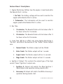
System Diagnostics
Alarm Diagnostics
When arming or disarming the alarm, this system will alert you of
alarm triggers or active inputs.
Arming Diagnostics:
When arming, if the door or hood is open the Horn/Siren output
and Parking Lights will pulse three times instead of once.
The LED will flash pause, and then repeat 5 times to indicate the
active input. (See alarm input chart.)
The active input will be bypassed. When it has been active for
more than 5 seconds it will be monitored by the system again. All
other alarm inputs will be monitored normally to assure the security of the vehicle
Disarming Diagnostics:
When disarming, if the alarm was fully triggered in your absence,
the Horn/Siren output and Parking Lights will pulse four times
instead of twice.
The LED will flash pause, and then repeat 5 times to indicate the
input that caused the trigger (See alarm input chart).
Note! If the alarm was triggered more than once, the
diagnostics will only report the last input that fully
triggered the alarm.
© 2007 Directed Electronics
63
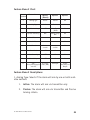
Alarm Input Chart
LED Flashes Input Description
The 'Gray/Blk' Input wire
1
The 'Orange' Brake Input wire
2
3
4
5
6
64
Sensor Input
Sensor Input
The 'Violet' Hood Input
The 'Blue' Ignition Input wire
© 2007 Directed Electronics
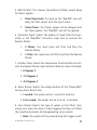
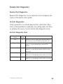
Remote Start Diagnostics
Remote Start Diagnostics:
Remote Start diagnostics are an important tool to diagnose the
status of the remote start system.
No Start Diagnostics:
If the system fails to activate Remote Start, Quick Stop, Daily
Start or Vacation Mode as expected, the parking lights will flash
to indicate the reason. Consult the No Start Diagnostic Chart.
No Start Diagnostic Chart
Remote Start
Feature
Any
LED
Description
Flashes
Indicates a loss of signal from the transmitter to
0
the system or a loss of power to the main unit.
Daily Start
3
Vacation Mode
3
Remote Start
5
QuickStop
5
© 2007 Directed Electronics
The unit is in the Valet Mode or Battery Voltage is
below 11v when attempting to activate this
feature.
The unit is in the Valet Mode, Battery Voltage is
below 11v, or the Brake, Hood or Ignition inputs
are active
The unit is in the Valet Mode, Battery Voltage is
below 11v, or the Brake or Hood inputs are active
The unit is in the Valet Mode, Battery Voltage is
below 11v, or the Brake or Hood inputs are active
65
Last Start Diagnostics:
The system holds in memory the reason for the most recent
remote start activation. To access this report:
1.
Turn the ignition ON and then OFF in less than 5 seconds
2.
Within 5 seconds Press and Release the Momentary
Switch
3.
After 2 seconds the LED will flashpause and repeat 5
times to indicate the cause of the most recent remote
start activation.
4.
Count the LED flashes and consult the Last Start
Diagnostic Chart.
Last Start Diagnostic Chart
LED
Flashes
1
66
Description
2
The Remote Starter has not been activated since the main power
was connected
The Transmitter was used to activate the Remote starter
3
The Activation Input wire was used to activate the Remote starter
4
Low temperature activated the Remote Starter in Vacation Mode
5
Low battery voltage activated the Remote Starter in Vacation Mode
6
No Diagnostics
7
Daily Start activated the Remote Starter
© 2007 Directed Electronics
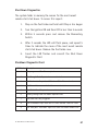
Shut Down Diagnostics:
The system holds in memory the reason for the most recent
remote start shut down. To access this report:
1.
Step on the foot brake and hold until Step 4 has begun
2.
Turn the ignition ON and then OFF in less than 5 seconds
3.
Within 5 seconds press and release the Momentary
Switch
4.
After 2 seconds the LED will flash pause, and repeat 5
times to indicate the cause of the most recent remote
start shut down. Release the foot brake now.
5.
Count the LED flashes and consult the Shut Down
Diagnostic Chart
Shutdown Diagnostic Chart
LED Flashes Description
1
The programmed Run Time expired
2
The 'Orange' Brake Input wire was activated
3
The Tachometer Input level fell below 50% of learned value
4
The Transmitter was used shut down remote start
5
The 'Violet' Hood Input wire was activated
6
Battery voltage level fell below required level
7
The alarm was fully triggered
8
The Tachometer Input level was x3 times learned value for >5sec
9
The "Red/Wht" activation Input was used shut down remote start
© 2007 Directed Electronics
67
Testing the System
Once steps 1-7 have been completed, the operation of the system
can be tested.
Ensure that the two 30-amp fuses are in the relay harness PINK
wire fuse holders. Make sure that the vehicle is in park with the
emergency brake on and the hood closed. Press
on the remote
to initiate the remote start function. The parking lights should
flash to confirm the remote start command has been received. The
accessories and ignition should turn on followed by the starter
cranking and the vehicle engine running (this may take a moment
to initiate). Pressing
on the remote will shut the engine off.
(See Programming System settings section for one-press remote
start operation)
This completes the testing. If all functions do not work correctly,
check your wiring against the manual and verify all connections.
If you still experience problems, contact Directed Technical
Support at 1-800-477-1382.
68
© 2007 Directed Electronics
Neutral Safety Test
Some vehicles do not have an electrical neutral safety switch.
Instead, a mechanical neutral safety switch that physically interrupts the starter wire is used when the vehicle is in any drive gear.
If the remote start is interfaced before this switch, it will provide
protection from starting in gear.
However, some vehicles combine the column shift mechanism and
the mechanical neutral safety switch into one mechanical part. In
these vehicles, it is impossible to interface the remote start
system before the neutral safety switch. With this type of vehicle,
if the car is left in a drive gear and the remote start system is activated, the vehicle will move and may cause damage to persons or
property.
Important! This test must be performed to determine if the vehicle will start while in gear. If the
vehicle attempts to start during this test you
must call Technical Support at 1-800-477-1382
for assistance before using the remote start feature.
Testing the Neutral Safety Switch
Note! You must complete the remote start system
installation before doing the following test.
Ensure that the remote start system is functioning normally. This includes connecting to the
brake as a shut-down.
1.
Make sure there is adequate clearance to the front and
rear of the vehicle because it may move slightly.
© 2007 Directed Electronics
69
2.
Make sure the hood is closed and there are no remote
start shut-downs active.
3.
Set the emergency brake.
4.
Turn the key to the "run" position, this will release the
shifter.
5.
Place the shifter in the drive position.
6.
Place your foot directly over the brake pedal, but do not
depress it. Be ready to step on the brake if the starter
engages.
7.
Activate the remote start system.
8.
If the starter does not engage, no additional safety
interfaces are required.
9.
If the starter engages, immediately depress the brake to
shut the remote start system down.
IF THE ENGINE ATTEMPTED TO START THE VEHICLE, THEN THE
VEHICLE HAS FAILED THE TEST
CALL TECHNICAL SUPPORT FOR ASSISTANCE AT 1-800-477-1382
Warning! If the vehicle fails this test, the remote
start must be disabled until the proper Safety
Interface has been installed that will keep the
vehicle from starting while in gear. Failure to do so
may result in property damage, injury or death.
70
© 2007 Directed Electronics
Troubleshooting
➜ The ignition comes on, but the starter will not crank.
Does it start with the key in the ignition? If so, does the vehicle
have an engine immobilizer? Does it start with the brake pedal
depressed? (Make sure to disconnect the brake shutdown when
performing this test.) If so, it may have a brake/starter interlock.
Is the correct starter wire being energized? Check by energizing it
yourself with a fused test lead.
➜ The starter cranks for 1 or 2 seconds, but does not start.
The wrong ignition wire is being energized or the system's ignition
and accessory wires have been connected backwards. Also, the
vehicle may have two ignition circuits. Try activating the unit with
the ignition key in the "run" position. If the vehicle then runs
normally, retest your ignition system.
➜ The starter continues to crank after the car has started.
Has the tach wire been learned? See the Tach Learning section of
this guide. Is the tach wire receiving the correct information?
Either the wrong tach wire has been used, or a bad connection
exists. Verify that all of the heavy gauge wires are plugged into
the correct tabs on the control unit. If they are incorrectly
connected, the starter could stay engaged.
➜ The climate control system does not work.
Either the wrong accessory wire is being energized or more than
one ignition or accessory wire must be energized in order to
operate the climate control system.
© 2007 Directed Electronics
71
➜ The remote start will not activate.
Check to ensure that the hood is not open and that the brake
pedal is not depressed. Check harnesses and connections. Make
sure the harnesses are fully plugged into the remote start module.
Make sure there are good connections to the vehicle wiring. Check
voltage and fuses. Use a meter and check for voltage between the
RED wire and the BLACK ground wire. If you have less than battery
voltage, check both 30A fuses on the main power wires. Also make
sure that the ground wire is going to a good paint-free chassis
ground.
➜ The remote start will activate but the starter never engages.
1. Check for voltage on the YELLOW starter wire two seconds
after the remote start becomes active. If there is voltage
present, skip to Step 4. If there is no voltage present,
advance to Step 2.
2. Check the 30A fuses.
3. Does the vehicle have an immobilizer? Some Immobilizer
systems will not allow the vehicle to crank if active.
4. Check connections. The two PINK heavy gauge input wires
should have solid connections. "T-taps", or "scotch locks" are
not recommended for any high current heavy gauge wiring.
Also, if the vehicle has more than one 12-volt input wire,
then connect one PINK wire to each.
72
© 2007 Directed Electronics
➜ The vehicle starts, but immediately dies.
Does the vehicle have an immobilizer? The vehicle's immobilizer
will cut the fuel and/or spark during unauthorized starting
attempts.
➜ The vehicle will start and run only for about 10 seconds.
Is the remote start module programmed for voltage sense? If so,
try programming the unit to tach mode, hooking up the tach wire,
and learning the tach signal.
© 2007 Directed Electronics
73
74
© 2007 Directed Electronics
Owner’s Guide
Now that the installation is complete and tested, it is time to
learn about the many outstanding features that are included in
your remote start, security and convenience system.
Remote Start Features
➤ Remote Start your engine to warm or cool your vehicle
before driving
➤ Quick Stop Mode will keep the vehicle interior warm or
cool during short trips away from the vehicle
➤ Daily Start for convenient engine warm up at a specific
time the following day
➤ Vacation Mode maintains battery level when the vehicle
is parked for extended periods
Security and Convenience features
➤ The built in alarm will keep your vehicle secure when
parked and remote started
➤ Keyless entry and starter kill outputs for convenience
and security
➤ Panic Mode feature to call for help if you are threatened
while in or near your vehicle
➤ CarFinder feature helps you find your vehicle in dark
parking lots
➤ Valet Mode will temporarily defeat the remote start and
alarm features, but leave the convenience feature available
© 2007 Directed Electronics
75
➤ Trunk release output will disarm your alarm and open
the trunk as you approach your vehicle. (Power trunk
release required.)
➤ Headlight output can operate as daytime running lights
for safety or light your way securely into your home or
office
➤ Switch Override will disarm the alarm system should you
loose your transmitter
➤ Silent Mode will defeat the chirps for remote start or
arm/disarm temporarily when needed
➤ Auto Re-arm will make sure your vehicle is locked at all
times if mistakenly unlocked
Transmitter Button Configuration
Using the Auto Learn operation for programming transmitters to
this system will result in the following transmitter icon operations.
controls the Remote Start/Stop functions
controls the CarFinder and Trunk Pop functions
controls the Headlight activation, Panic & Silent mode
functions
controls the Alarm Arm and Locking functions
controls the Alarm Disarm and Unlocking functions
76
&
activates the Vacation Mode feature
&
activates the Daily Start feature
© 2007 Directed Electronics
USING YOUR SYSTEM
The Remote Start, Alarm and Convenience features described in
this section follow the Auto-Learn step transmitter button assignments.
Remote Start Features
Remote Start allows you to remotely start and run your vehicle for
a programmed period of time. This makes it possible to warm up
the engine, as well as adjust the interior temperature of the
vehicle with the climate control system. If interior heating or
cooling is desired, the climate controls must be preset, and the fan
blower must be set to the desired level prior to remote starting the
vehicle.
Remote Start operation is completely disabled by placing the
system into the Valet Mode. The Remote Start, Quick Stop, Daily
Start and Vacation Mode features will not operate when in the
Valet Mode. See the Alarm Features section for information on
entering Valet Mode.
Remote Start the vehicle:
➤
Press the
➤
The parking lights will flash once and the Horn/Siren
will chirp once to confirm that the vehicle will attempt
to start.
➤
The engine will start a few seconds after the parking
lights flash.
➤
Once started, the lights will flash and it will run for the
programmed period of time
© 2007 Directed Electronics
button of the transmitter twice.
77
Note! If the lights flash more than once and the
engine does not start, refer to the No Start
Diagnostics for the cause.
Important! Never remote start your vehicle when the
keys are in the ignition, except when activating
Quick Stop mode. Never start the vehicle if it is not
in PARK and the Parking brake is not set.
Important! It is unsafe to operate a vehicle's motor
in a garage or other closed off area. Breathing the
exhaust from the vehicle is hazardous to your health.
Never activate the remote start in an enclosed space.
When you are ready to drive the vehicle:
➤ Insert the ignition key and turn it to the ON (not the
START) position.
➤ Press the brake pedal. The remote start will shut down
and the engine will continue to run.
Note! If the brake pedal is pressed before the key is
in the ON position, the engine will shut down.
The remote start can be shut down in several ways for convenience
by the user or for safety by the shut down inputs.
To shut down remote start:
78
➤
Press the transmitter
➤
Pulse the activation input wire twice
➤
Step on the brake.
button twice.
© 2007 Directed Electronics
Safety shut down inputs:
While the vehicle is running during remote start operation, the
system will monitor the vehicle and will automatically shut down
the engine if the system receives any of the following signals:
➤
The brake pedal is pressed.
➤
The hood is opened.
➤
The programmed run time has elapsed.
➤
The alarm is triggered.
➤
Low battery voltage.
➤
High or low tachometer signal.
Quick Stop Mode
The Quick Stop feature allows the vehicle to remain running after
the key has been removed from the ignition. This feature is useful
for occasions when you wish to exit and lock the vehicle for short
periods of time, but would like to leave the motor running and the
climate controls on.
To activate Quick Stop:
➤ With the ignition On and the engine running, do one of
the following:
■
Press and release on the transmitter
twice.
■
Press and release the Momentary Switch 4 times
quickly
■
Pulse the activation input wire twice
button
➤ The Horn/Siren will chirp once and the lights will begin
© 2007 Directed Electronics
79
flashing to indicate Quick Stop Mode is active.
➤ Turn the ignition key to the OFF position. (The engine
will stay running.)
➤ Exit the vehicle and arm/lock the doors.
➤ The engine will run for the programmed run time or until
a shut down input is activated.
Note! Quick Stop mode will not activate if the
brake pedal is depressed.
Daily Start
The Daily Start feature will automatically start the engine 24 hours
after it has been activated. This is convenient if you leave your
house for work at the same time every day. Simply activate as
described 24 hours before you wish for the engine to start.
To activate Daily Start:
➤ Press and hold the
&
buttons on your transmitter for more than 3 seconds
➤ The parking lights will flash 4 times and the Horn/siren
will chirp once to confirm Daily Start is activated.
➤ Your vehicles’ engine will Remote Start in 24 hours.
Note! The alarm and remote start functions will be
fully operational while Daily Start is active.
Important! When Daily Start is active ONLY park you
car in a well ventilated areas.
80
© 2007 Directed Electronics
To de-activate Daily Start:
➤ Press and hold the
&
buttons on your transmitter for more than 3 seconds
➤ Activate Vacation Mode
➤ The parking lights will flash 4 times to confirm Daily
Start has been de-activated. (The Horn/siren will not
chirp)
Vacation Mode
Vacation mode is a valuable feature designed to maintain normal
operating conditions when the vehicle is parked for extended
periods. Vacation mode will monitor and automatically start the
engine any time the system detects extremely low battery voltage
or temperatures (See Programming Section for available low
temperature settings).
To activate Vacation Mode:
➤ Press and hold the
&
buttons on your transmitter for more than 3 seconds
➤ The parking lights will flash 5 times and the Horn/Siren
will chirp once to confirm Vacation Mode is activated.
➤ Your vehicles’ battery level and interior temperature will
be monitored, and the engine will automatically start up
to 8 times.
➤ Temperature: the system will check the interior temperature and start if required every three hours
➤ Battery level: the system will start the engine immediately when the battery level drops below 11.5 volts.
© 2007 Directed Electronics
81
Note! The alarm functions will be fully operational
while Vacation mode is activated.
Important! When Vacation mode is activated, ONLY
park you car in a well ventilated areas.
To de-activate Vacation Mode:
➤ Press and hold the
&
buttons on your transmitter for more than 3 seconds
➤ Activate Daily Start
➤ Activate the Ignition, Hood or Brake inputs at any time
➤ The parking lights will flash 5 times to confirm Vacation
mode has been de-activated. (The Horn/siren will not
chirp)
82
© 2007 Directed Electronics
Alarm and Security Features
Transmitter Arming of the Alarm
You can arm the system by pressing the
button of your transmitter for one second. When the system arms, the Horn/Siren
output will chirp once and the parking lights will flash once.
If the power door locks are controlled by the system, the doors will
also lock. While the system is armed, the status LED will flash once
per second, indicating that the system is actively protecting your
vehicle.
If the Horn/Siren pulses and the lights flash 3 times, refer to the
Diagnostics Section. This indicates an alarm input is active at the
time of arming and should be checked. The LED will flash in groups
to indicate the active input.
Passive Arming of the Alarm
This system can be programmed to arm itself automatically (called
passive arming). If the system is programmed for passive arming,
it will automatically arm 30 seconds after the ignition is turned
off and the system detects that you have left the vehicle by
opening and closing a door.
Whenever the system is in its 30-second passive arming countdown, the status LED will flash rapidly. At the 30-second point,
the Horn/Siren will chirp and the parking lights will flash to indicate that the system is armed.
Note! If the door, brake or hood inputs are activated during the 30 second countdown the
timer will stop and reset, it will re-start once
the input becomes inactive. Active sensor
inputs will not stop the countdown.
© 2007 Directed Electronics
83
Auto-rearming feature
Auto-rearming is designed to protect the vehicle in case of unintended disarming of the alarm.
It will automatically re-arm the alarm and lock the doors 120
seconds after any transmitter disarm occurs.
To stop Auto-rearm, open a door or turn the ignition on before the
120 seconds expires.
Alarm Input Operations
When armed, the alarm has 6 inputs which can cause a full alarm
trigger output. Refer to the Alarm Diagnostic section for additional detail.
➤ The Door, Hood, Ignition and Brake inputs will cause an
immediate full trigger output when activated.
➤ The Sensor inputs can cause two types of outputs;
Warn-away and Full Trigger.
Note! An optional two-stage sensor (p/n 504d) is
required for the Sensor outputs to activate. Call
Technical Support for more information on compatible
sensors.
Alarm Trigger Outputs
➤ Warn-away output: this output consists of 5 chirps of
the Horn/Siren output and 3 flashes of the parking
lights.
➤ Full Trigger output: this output consists of flashing the
Parking lights and the Horn/Siren output for 30 seconds
followed by a 5 second pause to monitor the alarm
inputs. If an alarm input is still active the output will
repeat.
84
© 2007 Directed Electronics
Transmitter Disarming the Alarm
To disarm the security system, press the
button of the transmitter. When the system disarms, the Horn/Siren output will chirp
twice and the parking lights will flash twice.
If the power door locks are controlled by the system, the doors will
also unlock. The LED will turn off and the vehicle can be entered.
If the Horn/Siren pulses and the lights flash 4 times, refer to the
Diagnostics Section. This indicates that the alarm was fully triggered in your absence. The LED will flash in groups to indicate the
input that caused the trigger.
Momentary Switch Disarming the Alarm
If your transmitter is lost or will not disarm the alarm, you can
manually override it using your ignition key and the Momentary
Switch.
To override the Alarm using the Momentary Switch
➤ Enter the vehicle. The alarm will sound.
➤ Insert the key into the ignition and turn it to the On
position.
➤ Immediately press and release the Momentary Switch 2
times.
➤ After 2 seconds, the alarm will disarm as though the
transmitter had been used.
Panic Mode
This system includes a Panic Mode operation that will alert other
around you if you are threatened while in or near your vehicle. Due
to state laws the Panic Mode is defeated when the ignition is on.
© 2007 Directed Electronics
85
To activate Panic Mode:
➤ Press and hold the
button on the transmitter for 6
seconds
➤ The Horn/Siren output and light flash will activate for
45 seconds
To de-activate Panic Mode:
➤ Press and release the
button on the transmitter
➤ Arm or Disarm the alarm system
Zone Bypass Feature
The Zone Bypass feature temporarily bypasses alarm inputs that
trigger excessively when the system is armed while monitoring the
other inputs for triggers. This keeps constant triggers due to environmental reasons from annoying the neighbors.
Protected entry bypass:
If the door, hood, brake or ignition inputs become activated
through three consecutive 30-second full trigger durations, it will
be bypassed until it has become inactive for more than 5 seconds.
Sensor bypass:
If one of the sensor inputs is triggered three times within 1 hour,
that input will be bypassed for 1 hour. If a trigger occurs on that
input while the bypass timer is active, the bypass timer will reset
to 1 hour.
You can Disarm and then Rearm the alarm to defeat the sensor
bypass at any time.
86
© 2007 Directed Electronics
Valet Mode
Valet Mode will defeat the alarm trigger and remote start operations while leaving all other security and convenience features
available such as Panic, Trunk Pop, Door Lock/Unlock and
Carfinder.
To enter Valet Mode:
➤ Press and hold the Momentary Switch.
➤ Turn the ignition On and Off in less than 5 seconds.
➤ Continue to hold the Momentary Switch.
➤ After 2 seconds the LED will turn solid. Valet Mode is
entered.
note! The LED will stay on only when the ignition
is off. After the ignition has been off for 24 hours
the LED will turn off until the ignition is cycled
on/off.
To exit Valet Mode:
➤ Press and hold the Momentary Switch.
➤ Turn the ignition On and Off in less than 5 seconds.
➤ Continue to hold the Momentary Switch.
➤ After 2 seconds the LED will turn off, Valet Mode is
exited.
© 2007 Directed Electronics
87
Convenience Features
Carfinder Feature
This feature allows you easily locate you vehicle in large and darkened parking areas by pulsing the lights and Horn/Siren outputs.
To activate Carfinder:
➤ Press and release the
button on the transmitter
➤ The headlight output, parking light output and the
Horn/siren output will pulse once
Silent Mode
Silent Mode allows you to temporarily delete the Horn/Siren
output when arming, disarming or activating remote start.
To use Silent Mode:
➤ Press and release quickly the
button on the trans-
mitter
➤ After 1 second press the transmitter button of the
feature to be activated without a Horn/Siren output
Note! 10 seconds after step 1, the Horn/Siren output
will be re-activated. If Silent mode is your preferred
normal operation the Horn/Siren output can be programmed off in the feature menus. Then using Silent
Mode will temporarily turn on the Horn/Siren output.
Headlight Control
This feature allows you to toggle the headlight output on and off
anytime the ignition is off.
88
© 2007 Directed Electronics
To activate the Headlights:
➤ Press and hold for 3 seconds the
button on the
transmitter and then release it.
➤ The headlight output toggle on/off according to its
present state.
Note! The headlight output timer is 25 seconds
and is controlled by the ignition input, according
to the programmed setting.
Trunk Pop
This feature allows you disarm the alarm, unlock the doors and
pop your trunk open with one press of a button
To activate the Trunk Pop:
➤ Press and hold the
button on the transmitter for 3
seconds.
➤ The alarm will disarm, unlock the doors and the auxiliary
output will pulse.
Note! The auxiliary output will stay active until
the transmitter button is released.
© 2007 Directed Electronics
89
Glossary of Terms
Control Module: The “brain” of your system. Usually hidden under
the dash area of the vehicle. It houses the microprocessor that
monitors your vehicle and controls all system functions.
FAD: Factory Alarm Disarm. Some vehicles with a factory alarm
require the alarm to be disarmed before remote starting.
RAP: Retained Accessory Power. After the vehicle is started and
then shut down, the power to the radio remains on (retained) until
a vehicle door is opened.
Transmitter: A hand-held, remote control which operates the various functions of your system.
90
© 2007 Directed Electronics
Notes
_____________________________________________________
_____________________________________________________
_____________________________________________________
_____________________________________________________
_____________________________________________________
_____________________________________________________
_____________________________________________________
_____________________________________________________
_____________________________________________________
_____________________________________________________
_____________________________________________________
_____________________________________________________
_____________________________________________________
_____________________________________________________
_____________________________________________________
_____________________________________________________
_____________________________________________________
_____________________________________________________
© 2007 Directed Electronics
91
92
© 2007 Directed Electronics
✂
Quick Reference Guide:
Cut along dotted line and fold for a quick and easy reference to keep in your purse or wallet.
Alarm Operation
■ To Arm and Lock: Press the
button for one second. The doors will lock
and the parking lights and Horn/Siren will pulse once.
■ To Disarm and Unlock: Press the
button for one second. The doors will
unlock and the parking lights and Horn/Siren will pulse twice.
Security and Convenience Features
■ Activate Panic Mode: Press and hold the
■ Activate CarFinder: Press/release the
button for 6 seconds.
button quickly.
■ Activate Headlights: Press and hold for 3 seconds and then release the
button.
■ Open the Trunk: Press and hold the
button for 3 seconds.
Remote Start the engine
■ To Start: Press the
button twice. The engine will start and the parking
lights will flash to confirm start.
■ To Stop: Perform the same steps as above to shut down remote start.
Quick Stop Mode
■ To activate: Press the
button twice with ignition on and the engine
running or press/release the Momentary Switch 4 times.
■ To de-activate: Press the
button twice or step on the brake.
Daily Start
■ To activate: Press the
and
buttons for three seconds. The lights
will flash 4 times and the Horn/Siren will chirp once to confirm.
■ To de-activate: Perform the same step to exit, the parking lights will flash
4 times, the Horn/siren will not pulse.
Vacation mode
■ To activate: Press the
and
buttons for three seconds. The lights
will flash 5 times and the Horn/Siren will chirp once to confirm.
✂
■ To de-activate: Perform the same step to exit, the parking lights will flash
5 times, the Horn/siren will not pulse.
© 2007 Directed Electronics
93
94
© 2007 Directed Electronics
© 2007 Directed Electronics
95
The company behind this system is Directed Electronics
Since its inception, Directed Electronics has had one purpose, to provide consumers with
the finest vehicle security and car stereo products and accessories available. The recipient of
nearly 100 patents and Innovations Awards in the field of advanced electronic
technology, DIRECTED is ISO 9001 registered.
Quality Directed Electronics products are sold and serviced throughout North America
and around the world.
Call (800) 274-0200 for more information about our products and services.
Directed Electronics is committed to delivering world class quality products
and services that excite and delight our customers.
Directed Electronics
Vista, CA 92081
www.directed.com
© 2007 Directed Electronics—All rights reserved
N24927 08-07