1
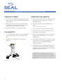
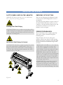
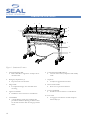
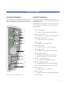
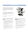
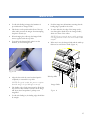
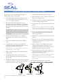
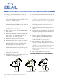
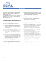
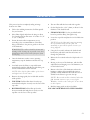
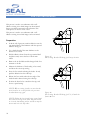
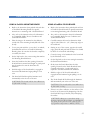
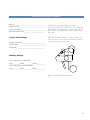
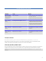
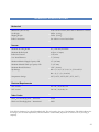
44 Ultra Laminator Owner’s Operation Manual 44 Ultra Laminator TABLE OF CONT ENTS TABLE OF CONTENTS ...................................................................................................................................................................2 INTRODUCTION................................................................................................................................................................................1 ELECTRICAL SPECIFICATIONS................................................................................................................................................4 INSTALLATION...................................................................................................................................................................................5 UNPACKING, SET-UP AND INSTALLATION....................................................................................................................6 UNPACKING, SET-UP AND INSTALLATION....................................................................................................................7 UNPACKING, SET-UP AND INSTALLATION....................................................................................................................8 IMPORTANT SAFEGUARDS.........................................................................................................................................................9 LAMINATOR FEATURES................................................................................................................................................................10 CONTROL PANEL .............................................................................................................................................................................11 OPERATING YOUR LAMINATOR............................................................................................................................................12 SET-UP AND OPERATION............................................................................................................................................................13 SET-UP AND OPERATION............................................................................................................................................................14 IMAGE GUIDE.....................................................................................................................................................................................15 WEBBING FILMS WITHOUT A RELEASE LINER............................................................................................................16 WEBBING FILMS WITH A RELEASE LINER (NORTH AMERICA) .........................................................................17 WEBBING FILMS WITH A RELEASE LINER (EUROPE & ASIA)..............................................................................18 DECALING.............................................................................................................................................................................................19 MOUNTING...........................................................................................................................................................................................20 ENCAPSULATING..............................................................................................................................................................................21 PRE-COATING BOARDS................................................................................................................................................................22 USING A ProSEAL ® MOUNTING BOARD & POUCH BOARDS...............................................................................23 ENCAPSULATING USING A ProSEAL ® FLEXIBLE POUCH WITH A ProSEAL ® SLED...............................24 PROCESS CONTROL SHEET........................................................................................................................................................25 CLEANING YOUR LAMINATOR..............................................................................................................................................26 TROUBLESHOOTING GUIDE....................................................................................................................................................27 GLOSSARY OF TERMS.....................................................................................................................................................................28 TECHNICAL SPECIFICATIONS..................................................................................................................................................29 LIMITED WARRANTY......................................................................................................................................................................30 2 INTRODUCTION Thank you for purchasing a SEAL ® 44 Ultra Laminator. We have designed the SEAL 44 Ultra to give you years of reliable service. The 44 Ultra brings a new level of simplicity and ease of use to image finishing. As you become familiar with your laminator, you will appreciate the high quality of its production and the excellence in its engineering design. By following the guidelines for proper care and use of the SEAL 44 Ultra, you can depend on many years of trouble-free profitability from your investment. The purpose of this manual is to outline the materials and process when using SEAL Brands supplies with your laminator to create signs, displays, and flexible graphics with professional results. The manual includes instructions of various laminating procedures, which are meant to give you comprehensive information needed for the efficient use of your laminator. Please read and fully understand the entire manual before proceeding to use your laminator. STATEMENT OF INTENDED USE Your SEAL 44 Ultra Laminator meets the CE Machinery Safety Directive (89/392/EEC, including 91/368/ EEC, 93/44/EEC and 93/68/EEC) and is cETL listed (UL 1950/EN60950). The SEAL 44 Ultra laminator has been designed to be used with SEAL Brands materials. When used with these products, you are able to mount, mount and laminate, and encapsulate prints in one step. Your laminator has been tested with SEAL Brands supplies and we recommend using these products for professional results. WARNING! This laminator is designed for mounting and laminating. Any use other than the intended may cause damage to the laminator or physical harm to the user. WARNING! Any unauthorized changes or modifications to this unit without our prior written approval will void the user’s warranty and will transfer health and safety obligations to the user. LIABILITY STATEMENT The details given in this manual are based on the most recent information available to us. They may be subject to change in the future. We retain the right to make changes to the construction or the design of our products without accepting any responsibility for modifying earlier versions previously delivered. CAUTION! Please pay attention to all passages marked this way. This information is vital to preventing user injury and/or damage to the unit. Failure to follow this information could void the user’s warranties and transfer all safety obligations to the user. 3 ELECTRICAL SPECIFICATIONS The electrical specifications of the laminators are: North American Version: EU Version: 110VAC 50/60Hz 16A 230VAC 50/60Hz 9A (Part No. 60959) (Part No. 60958) For the North American version, For the EU versions, Mainland Europe, the following is applicable: the following is applicable: G L N France Belgium NEMA 5-20R Using 20 Amp Breaker Note: T-slot is not applicable for Canada Germany, The Netherlands Portugal, Spain Use the provided Schuko plug (10A). For the EU versions, in the UK, the following is applicable: BS 1363 – 13A wall receptacle: Use the provided BS 1363 plug 4 INSTALLATION ENVIRONMENT CONDITIONS The following environmental conditions are ideal for the best operation of the laminator. Once power is connected to your laminator, press the Power button on the control panel to turn the laminator ON. If the Power LED does not come on, refer to the “Troubleshooting” page for problem solving information. AMBIENT TEMPERATURE The best temperature for the SEAL ® 44 Ultra is between 50°F and 95°F (16°C and 35°C). Do not expose the laminator to direct sunlight as output quality may be affected. RELATIVE HUMIDITY For best results, the ambient relative humidity for the SEAL 44 Ultra should be between 70-90% noncondensing. Too much humidity will affect the prints being laminated causing problems with film adhesion. WATER AND MOISTURE If the laminator is installed in a damp room or near water, the electrical power supply must be in accordance with the standards prevailing in the country concerned. SURROUNDINGS Install the laminator in surroundings that are as clean and dust free as possible in order to obtain the highest quality output. The background dust level must not exceed that found in a typical office/computer room environment. The materials that are used on this laminator can have an electrostatic charge and will attract dust, adversely affecting the output. POWER SUPPLY Connect the laminator in accordance with the details given on the identification plate attached to the rear of the laminator. Refer also to the Technical Specifications page for more information. WORKSPACE REQUIREMENTS • This unit should be situated away from heat sources such as heat registers or stoves/ovens. • The laminator’s location or position should not interfere with its proper ventilation. • There should be enough space around the laminator to feed, receive and trim mounted and/or laminated images. • Keep the area around your laminator clear with adequate space around it so you can feed, receive and trim mounted and/or laminated images. • The work area should be level, flat, and well lit. Accessories Included: • Wrench 17-24 mm • 10 each Socket head screws • 10 each Star Washers • 2 each Spare Fuses (250V) • Allen key (5 mm) • Snitty® Safety Knife • Image Roll Cleaner • Spare Core for Wind-up Idler • Leader-board • Owner’s Manual 5 UNPACKING, SET-UP AND INSTALLATION Remove the cardboard box and the plastic bag as described on the outside of the box. Remove and open the boxes behind the laminator, which contains the stand parts. SETTING UP THE LAMINATOR IN 4 STEPS STEP 1 • Mount the left-hand stand leg onto the underside of the laminator, as shown in Figure 1. (Note: The left-hand section is recognizable by a spring utility on the bracket.) • Use two star washers and two sockethead screws. • Do not tighten these screws completely. Figure 1. STEP 2 • Mount the right-hand stand leg onto underside of the laminator, as shown in Figure 2. • Use two star washers and two sockethead screws. • Do not tighten these screws completely. 6 Figure 2. UNPACKING, S E T -UP AND INSTALLATION STEP 3 • Now mount the middle support section between the left-hand and right-hand stand legs, as shown in Figure 3. • Use six star washers and six sockethead screws. • Tighten these six screws. • Finally, tighten all screws, which were used in Steps 1 and 2. Figure 3. STEP 4 • Carefully lift the laminator (at least two people must do this!) from the pallet and position it onto its castors as shown in Figure 4. • Make sure that the stand legs do not slide away during lifting. • Cut the strap and remove the protective covers. Figure 4. 7 UNPACKING, SET-UP AND INSTALLATION LAMINATOR PLACEMENT CONNECTING YOUR LAMINATOR • Your SEAL ® 44 Ultra must be setup in the location where it will be used. The stand must be placed on a flat level surface. • Plug the power cable into the grounded outlet with the appropriate service. (Refer to the Electrical Specifications Page) • Remove the tie-wraps by using a small flat-edged screwdriver to press the clip to release the tie and remove the blocks that hold the top roller. • The SEAL 44 Ultra must be installed next to an outlet! Inspect the laminator for any physical damage. • The plug and the outlet must be easily accessible. • Please ensure that you plug your laminator into a grounded, three-prong outlet. • ADJUSTABLE FEET Do not use extension cords! • To secure the stand on the floor, turn the adjustable foot down by hand, until it’s pressed against the floor. • Please ensure that the total load of the other items using the same circuit breaker do not exceed its breaking value. • Manually lock the adjustable foot with the nut. (Figure 5) • The laminator should only be connected to a power supply outlet of the voltage and amperage marked on the rear panel. (See Identification Plate on laminator rear panel.) • The laminator has a grounded plug (three prongs). To reduce the risk of electrical shock, this plug is intended to fit only a grounded outlet of the proper amperage, and only in one way. Nut Feet Figure 5 8 WARNING! Any unauthorized changes or modifications to this unit without our prior written approval will void the user’s warranty and will transfer health and safety obligations to the user. IMPORTANT SAFEGUARDS SAFETY SYMBOLS USED ON THE LAMINATOR EMERGENCY STOP-BUTTONS IMPORTANT! Read and make sure you understand these safety and operating guidelines. There are two Emergency-Stop Buttons located on the top of the left and right plastic covers of the laminator. Rotating Parts: Risk Of Injury CAUTION! Failure to use caution near rotating rollers could result in physical injury. Be careful that items such as loose clothing, long hair and jewelry do not become entangled in rotating parts. Hot Surface: Risk Of Injury On Contact CAUTION! The laminator contains heated rollers, which may reach temperatures of 250°F (121°C). There is a danger of burns if the heated roller is touched during use. Even after switching off the laminator, the roller remains hot for a long time. The Emergency-Stop Buttons stop the rotation of the rollers and should only be used in case of an emergency. Once pressed, these buttons lock, and they must be rotated to be reset before the laminator can be used again. PREVENTATIVE MEASURES: Do not feed objects such as staples, paper clips and rough or abrasive materials through the laminating rollers. Keep all objects, such as tools, rulers, pens, markers or knives away from the roller opening. Refrain from leaving such items on the front table to prevent them from accidentally being fed into the rollers. IMPORTANT! NEVER cut or slice directly on the rollers as any cuts or gouges will destroy them. ALWAYS use cutters with enclosed blades to prevent cutting the rollers and to avoid extensive replacement costs. WARNING! Always adjust the Nip-knob setting to create a gap between the laminating rollers to prevent flat spots from developing when the laminator is not in use. Flat spots will affect the quality of the output and void the warranty replacement. IMPORTANT! The main rollers should be together and turning while heating up to prevent uneven hot spots on the roller. A stationary roller will develop concentrated heat in one area, which will damage the roller. Figure 6 9 LAMINATOR FEATURES 2 3 4 5 2 1 6 7 8 9 10 Figure 7. Laminator Features 1. Automatic Wind-up Idler • Removable idler to support the wind-up core for the release liner. 6. Control Panel with LED indicators • Controls roller rotation, temperature and standby mode. 2. Emergency Stop Buttons (2) • Stops the rotation of the rollers. 7. Nip-knob • To adjust the gap between the rollers. 3. Image Guide • To help feed in images. It is removable when mounting. 8. Process Control Label • Shows how to preset the laminator. 9. 4. Upper Unwind Shaft • Suitable for rolls wound onto a 3-inch ID core. Lower Unwind Shaft • Suitable for rolls wound onto a 3-inch ID core. 5. Unwind Brake • A simple braking system with a knurled collar provides the means of adjusting the brake tension for the films. Fitted on both the autogrip unwind shafts. 10 10. Foot switch • To engage slow-mode that overrides the photoelectric safety eyes. CONTROL PANEL LED INDICATOR DESIGN PUSH BUTTON DESIGN The LED indicators are designed to indicate the on/off status of power, heat, and roller direction. Please see below for the definitions of the LED status indicators. The Push Buttons control whether power and heat is on or off and the direction the rolls turn. Please see below for detailed instructions. NOTE: Push the Power Button (at least one-second) and the forward (or reverse) button on the control panel, to run the laminator. 1 2 3 4 1. LED - Forward Run • Lit when the rollers run in forwards direction 2. Button - Forward Run • Push button to run rollers in forwards direction 5 3. LED Optical Safety System • Lit when light beam is not interrupted 6 4. Button - Stop • Push button to stop roller rotation. 5. LED – Reverse Run • Lit when the rollers run in reverse direction. 7 8 9 10 11 6. Button - Reverse Run • Push button to run rollers in reverse direction. 7. Speed Adjustment Knob • Each whole number represents an increase or decrease in speed of 6”/ min (15 cm/min) 8. LED’s - Temperature Settings • Lit to correspond to temperature setting 9. Button -Temperature Setting • Toggle push button to preset the temperature. (Press 2 seconds to switch the heating system off) 10. LED – Power • Lit when laminator is switched on. Figure 8. Control Panel Diagram 11. Button – Power • Toggle push-button to turn laminator ON/OFF (Press 2 seconds). 11 OPERATING YOUR LAMINATOR MOTOR CONTROL The speed of the rollers is continuously adjustable between 0 and 1.5 m/min. (0 and 4.8 ft/min.) Pressing the ñ button runs the rollers in the forward direction, pressing the ò button reverses the direction of the rollers. The stop button stops the roller movement. CHANGING FROM NORMAL MODE TO SLOWMODE WITHOUT STOPPING: • Press the foot switch. NOTE: Releasing the foot switch will stop the laminator. SLOW-MODE OPERATION REVERSING THE ROLLER ROTATION The laminator has a slow-mode, which can be activated by pressing the foot switch. • To reverse the rotation of the rollers, press the ò (reverse) button. • To maintain slow-mode, keep the foot switch pressed. • • This feature can be used when loading materials onto the laminator and overrides the photo-electric safety eyes. As long as the button is pressed, the laminator will run in the reverse direction, at a speed of 0.6m/min. (2 ft/min) only. • Releasing the button will stop the laminator. CAUTION! Take care so that loose clothing, long hair, jewelry and fingers are not pinched between the pull rollers at the rear side of the laminator. CAUTION! Once the laminator is running in slow-mode, interrupting the photo-electric safety eyes does NOT stop the laminator. An audible beep will be heard and the roller speed will be 0.6 m/min. (2 ft/min). Releasing the foot switch will stop the laminator. THE ROTATION OF THE ROLLERS WILL STOP WHEN: CHANGING FROM SLOW-MODE TO NORMAL RUNNING MODE WITHOUT STOPPING (to prevent stop marks on the substrate): • • The photo-electric eyes in front of the main rollers are interrupted. NOTE: This does NOT happen when the foot switch is used (slow-mode). During slow-mode (keep the foot switch pressed), press the ñ (forward) button on the control panel. The laminator will run at the pre-set speed. • An emergency stop button is pressed. • The foot switch is pressed for a short moment. • Next, release the foot switch. • • Finally, release the ñ (forward) button. Excessive unwind tensions are set (the motor will be shut off electronically. Press the stop button on the control panel to reset). • The stop button on the control panel is pressed. 12 S E T -UP AND OPERATION The following steps outline the basic procedures that have to be used for loading films; setting the nips, webbing the laminator and setting the brake tension for the films you will be using. To load and unload the unwind shafts, it is necessary to access the laminator from the rear side. 2 Select the film(s) that you will use on the top (and bottom) of the images. It is advisable to use films slightly wider than the print width. This way the print can be trimmed with a border, to reduce waste, yet leave enough for a border. 1 ALWAYS WORK IN THE CENTER OF THE LAMINATOR. Figure 9 LOADING THE FILM ONTO THE UNWIND SHAFT LOADING THE UNWIND SHAFT INTO THE LAMINATOR • • Place the unwind shaft (2), top or bottom including the material, into the laminator by inserting it onto the left-hand unwind shaft holder. • Push the interlock bracket (1) upward with your finger before sliding the unwind shaft further. (Figure 9) Remove the desired unwind shaft (2), top or bottom by pushing the interlock bracket (1) in the upper position and sliding the unwind shaft to the right against the spring pressure. (Figure 9) • Release the interlock bracket when the shaft is completely to the right. • Lift the unwind shaft out of the laminator. • • Slide the shaft into a film roll. Ensure that the rubber blocking cords are on the top and bottom of the shaft for easy loading. Press against the spring pressure, until you can place the other end of the shaft onto the right-hand holder and onto the left-hand side holder. • Center the film roll in the laminator. • Rotate the unwind shaft until it locks into the unwind brake. Take care that the ends of the shaft do not become damaged during the loading and unloading. 13 S E T -UP AND OPERATION SETTING THE UNWIND BRAKE TENSION HOW TO SET THE NIP: (Refer to the Features Page for identification.) • First, determine the thickness of the board that you will use for mounting. • Grasp the Nip-knob with your right hand and push it in approximately 1/4” (6mm) to the left. • Once the Nip-knob has disengaged from the stop, it may be rotated forward or backward (clockwise or counter-clockwise, as viewed from the right hand side of the unit). • Turn until the desired measurement corresponds with the indicator window at the base of the knob. • Releasing the Nip-knob so that it moves back to the right and clicks into place will set the rollers for use. • The measurements on the Nip-knob correspond to the board thickness. • There is also a fully closed stop 0” (0 mm) for film only applications. • • Tighten the unwind brake so that it applies sufficient tension to the laminate. Turning the unwind brake in a clockwise direction increases the braking tension applied on the laminate. • Turning the unwind brake in a counter-clockwise direction decreases the braking tension. • The best setting for the unwind brake tension is determined by the materials you are using and is learned through experience. TEMPERATURE SETTINGS • Select the film(s) that you will use on the top (and bottom) of the images. • Check which temperature setting is recommended for your SEAL ® Brands material (see literature enclosed in your material box). • Refer to the Control Panel Diagram for information on setting the temperature. ROLLER NIP SETTINGS Whenever you mount onto a board, etc., it is important to adjust the rollers to create a gap nearly equal to the thickness of the board being used. This is done so that anything passing between the rollers will receive the right amount of pressure and prevent damage to the roller’s silicone surface (and possibly the board). 14 NOTE: For non-standard substrate thickness, select the next lowest nip setting, i.e. 7mm board – select 1/4” (6mm) nip. IMAGE GUIDE • To aid with feeding in images, the laminator is provided with an “Image Guide”. • Feed the image into the laminator ensuring that the leading edge is parallel to the roller. • This device can be positioned in front of the top roller and it prevents the images from interrupting the photo-electric eyes. • To assist with this, the edge of the image can be seen through the windows in the “Image Guide”, which is in front of the rollers. • When changing the roller nip, the Image Guide moves together with the top roller. • To position the Image Guide, place it on the brackets, as shown in Figure 10. NOTE: Do not stop the motor while an image is being finished as this can cause marks in the output. • When not in use, the Image Guide and the wind-up idler can be stored in the stand. (Figure 11) Figure 10 • Align the slots with the screw head and push it completely in towards the top roller. NOTE: For good results, the process requires that the images be fed through correctly. • • The leading edge of each image must be flat all the way across or any wrinkles or creases in the image will show when encapsulated - perhaps even magnified. Wind-up Idler Image Guide Figure 11 To aid with feeding in, the leading edge should also be straight. 15 WEBBING FILMS WITHOUT A RELEASE LINER The following are the basic webbing procedures for webbing films without a release liner: • • Select films slightly wider than the image to allow for a border without film waste. A border of 1/8” to 1/4” (3-6 mm) is adequate. Ensure the main roller’s temperatures are set according to the recommendations of the laminates being used (see literature enclosed in your material box). Refer to the process guide on the front of the laminator. WARNING! The rollers should be together and turning while heating up to provide even heat distribution and prevent roller flat spots from developing. • Once the laminator reaches correct operating temperature, stop the laminator and raise the top roller. • Pivot the front table down for easier webbing access. • Load and center the films on top and bottom unwind shafts with the dull adhesive side facing out and the unwind brake tension released. NOTE: Check if the film widths of the lower and upper web are the same! • Remove the image guide, the in-feed table and the wind-up idler. • TOP FILM: Pull the film down from the top unwind shaft, and place it evenly over the face of the top roller. • BOTTOM FILM: Pull the film up from the bottom unwind shaft and place it evenly over the top film draped over the face of the top roller. TOP FILM Figure 12. Webbing films w/o Release Liners 16 • The two films will then heat and stick together. • Set the Nip-knob to 1/16” (2mm) to allow for the thickness of a leader-board. • FILMS INTO NIP: Use the provided leader-board to push the film(s) through the nip. • Lower the top roller and place the in-feed table into position. NOTE: Keep the film under tension (holding back on the top unwind shaft, not the film roll) to prevent the photo-electric eyes being tripped. • Using the footswitch, advance the leader-board between the pull rollers until the end comes out through the pull rollers. • Release the foot switch and set the Nip-knob to ‘0’, (0 mm). • Moving to the rear of the laminator, with the film and leader-board hanging out of the laminator, cut off the leader-board. • Return to the front of the laminator and run the laminator, applying light unwind brake tension gradually on both unwind shafts until there are no wrinkles in the film as it goes into the nip. • Run the laminator for about 3 feet (1 meter), to work out any wrinkles. If wrinkles persist, cut the film and web the laminator again. NOTE: Best results will be obtained when the film unwind tension is zero or very light. Wrinkles, visible on the roller face do not show on the output. • Refit the image guide on the in-feed table. YOU ARE NOW READY TO FEED IMAGES! BOTTOM FILM FILM INTO NIPS WEBBING FILMS WITH A RELEASE LINER (NORTH AMERICA) The following are the basic webbing procedures for webbing films with a release liner: • Lower the top roller and place the in-feed table into position. • Select films slightly wider than the image to allow for a border without film waste. A border of 1/8” to 1/4” (3 - 6mm) is adequate. • Load and center the films on top and bottom unwind shafts with the dull adhesive side facing out and the unwind brake tension released. • Using the footswitch, advance the leader-board between the pull rollers until the end comes out through the pull rollers. NOTE: Check if the film widths of the lower and upper web are the same! • Release the foot switch and set the Nip-knob to ‘0’, (0 mm). • Remove the image guide, the in-feed table and the wind-up idler. • • TOP FILM: (film with a release liner) Pull the film down from the top unw ind shaft, and place it evenly over the face of the top roller. Moving to the rear of the laminator, with the film and leader-board hanging out of the laminator, cut off the leader-board. • Return to the front of the laminator and run the laminator, applying light unwind brake tension gradually on both unwind shafts until there are no wrinkles in the film as it goes into the nip. • Run the laminator for about 3 feet (1 meter), to work out any wrinkles. If wrinkles persist, cut the film and web the laminator again. • Replace the wind-up idler into the brackets. • RELEASE LINER: Place the spare core between the wind-up idler and the top main roller. Separate the film from the release liner. Attach the release liner to the spare core using a piece of tape. • BOTTOM FILM: Pull the film up from the bottom unwind shaft and place it evenly over the top film draped over the face of the top roller. • Set the Nip-knob to 1/16” (2mm) to allow for the thickness of the leader-board. • FILMS INTO NIP: Use the provided leader-board to push the film(s) through the nip. TOP FILM NOTE: Keep the film under tension (holding back on the top unwind shaft, not the film roll) to prevent the photo-electric eyes being tripped. NOTE: Best results will be obtained when the film unwind tension is zero or very light. Wrinkles, visible on the roller face do not show on the output. • Refit the image guide on the in-feed table. YOU ARE NOW READY TO FEED IMAGES! BOTTOM FILM FILM INTO NIPS Figure 13. Webbing films with Release Liners 17 WEBBING FILMS WITH A RELEASE LINER (EUROPE & ASIA) • The following are the basic webbing procedures for webbing films with a release liner: Lower the top roller and place the in-feed table into position. • Select films slightly wider than the image to allow for a border without film waste. A border of 1/8” to 1/4” (3 - 6mm) is adequate. • Load and center the films on top and bottom unwind shafts with the dull adhesive side facing out and the unwind brake tension released. • Using the footswitch, advance the leader-board between the pull rollers until the end comes out through the pull rollers. NOTE: Check if the film widths of the lower and upper web are the same! • Release the foot switch and set the Nip-knob to ‘0’, (0 mm). • Remove the image guide, the in-feed table and the wind-up idler. • • TOP FILM: (film with a release liner) Pull the film down from the top unwind shaft, and place it evenly over the face of the top roller. Moving to the rear of the laminator, with the film and leader-board hanging out of the laminator, cut off the leader-board. • Return to the front of the laminator and run the laminator, applying light unwind brake tension gradually on both unwind shafts until there are no wrinkles in the film as it goes into the nip. • Run the laminator for about 3 feet (1 meter), to work out any wrinkles. If wrinkles persist, cut the film and web the laminator again. • Replace the wind-up idler into the brackets. • RELEASE LINER: Place the spare core between the wind-up idler and the top main roller. Separate the film from the release liner. Attach the release liner to the spare core using a piece of tape. • BOTTOM FILM: Pull the film up from the bottom unwind shaft and place it evenly over the top film draped over the face of the top roller. • Set the Nip-knob to 1/16” (2mm) to allow for the thickness of the leader-board. • FILMS INTO NIP: Use the provided leader-board to push the film(s) through the nip. TOP FILM Figure 14. Webbing films with Release Liners 18 NOTE: Keep the film under tension (holding back on the top unwind shaft, not the film roll) to prevent the photo-electric eyes being tripped. NOTE: Best results will be obtained when the film unwind tension is zero or very light. Wrinkles, visible on the roller face do not show on the output. • Refit the image guide on the in-feed table. YOU ARE NOW READY TO FEED IMAGES! BOTTOM FILM FILM INTO NIPS DECALING This process involves sandwiching an image between a pressure-sensitive or heat-activated laminate on the face of the image and a pressure-sensitive adhesive on the rear. This process can be used to create self-adhesive images for mounting down onto various substrates. After performing this process, follow the Mounting Instructions in the manual to apply the decal to a substrate. • Select films slightly wider than the image to allow for a border without film waste. A border of 1/8” to 1/4” is adequate. • Refer to the process guide on the front of the laminator for settings and recommended film combinations. • Follow the webbing instructions for the type of films being used which are specific to your location. 19 MOU N T I N G This process involves mounting previously prepared decals onto a substrate. No films or adhesives are required for this process. • Flip the un-tacked portion of the image over the top roller with one hand so that the release paper can be peeled off the image with the other hand. To perform this process, it is necessary to remove the Image Guide. You can store the Image Guide in the laminator stand (Figure 9). • Depress the foot switch to feed the board through the rollers. • At this point, continuous run can be selected by pressing one of the speed settings. TO MOUNT DECALS ONTO A SUBSTRATE NOTE: Take care that the rollers do not grab the liner. • Place the mounting board on a flat surface. • Lay your image face down on the mounting board and expose approximately 1” (25 mm) of the adhesive by peeling back the release paper along one of the edges. • When the end of the board is near the nip, you may want to slow the laminator down. To do this, just press the foot switch to go into slow-mode. Releasing the foot switch will stop the laminator. • Fold the release paper back making an even crease. • • Turn the image over and carefully position the exposed adhesive edge of the image squarely onto the board. Remove the mounted image from the rear of the laminator and trim it if necessary. • • Once positioned correctly, press the image firmly down onto the exposed adhesive from the center toward the edges to ensure smooth surface. This is the edge that will be fed into the rollers first. If the board is accidentally sent in too far at first, the release liner will get caught and will be impossible to pull back. In this case, stop and reverse the motor until the liner can be pulled away. • • Ensure that the nip setting of the rollers corresponds to the board thickness. The image must be held against the roller while the board feeds through to prevent wrinkles. As the process becomes more familiar, the speed of the laminator may be increased to make the process more efficient. • Push the edge of the board into the rollers and depress the foot switch until the board and image are just caught by the nip. NOTE: Take care that the release liner does not trip the optical safety system. 20 ENCAPSULATING This process involves completely sealing an image between two films. • Follow the webbing instructions for films specific for your location. • Select films slightly wider than the image to allow for a border without film waste. A border of 1/8” to 1/4” is adequate. • • The two films will then heat and stick together. • Set the Nip-knob to 1/16” (2mm) to allow for the thickness of the leader-board. • FILMS INTO NIP: Use the provided leaderboard to push the film(s) through the nip. • Lower the top roller and place the in-feed table into position. Ensure the main roller’s temperatures are set according to the recommendations of the films being used. Refer to the process guide on the front of the laminator. WARNING! The rollers should be down and turning while heating up to provide even heat distribution and prevent roller flat spots from developing. • • Once the laminator reaches correct operating temperature, stop the laminator and raise the top roller. Load and center the films on top and bottom unwind shafts with the dull adhesive side facing out and the unwind brake tension released. NOTE: Keep the film under tension (turning the top unwind shaft, not the film roll manually) to prevent the photo-electric eyes being tripped. • Using the foot switch, advance the leader-board between the pull rollers until the end comes out through the pull-rollers. • Release the foot switch and set the Nip-knob to ‘0’ (0mm). • Moving to the rear of the laminator, with the film and leader-board hanging out of the laminator, cut off the leader-board. • Return to the front of the laminator and run the laminator, applying light unwind brake tension gradually on both unwind shafts until there are no wrinkles in the film as it goes into the nip. NOTE: Check if the film widths of the lower and upper web are the same! • Remove the image guide, the in-feed table and the wind-up idler • TOP FILM: Pull the film down from the top unwind shaft and place it evenly over the face of the top roller. • BOTTOM FILM: Pull the film up from the bottom unwind shaft and place it evenly over the top film over the face of the top roller. NOTE: Best results will be obtained when the film unwind tension is zero or very light. Wrinkles, visible on the roller face do not show on the output. • Refit the image guide on the in-feed table. YOU ARE NOW READY TO FEED IMAGES! 21 P R E -COATING BOARDS This process is used to coat substrates with a selfadhesive coating onto which images can be mounted. Images can then be mounted on the substrate. This same process is used to create a sled. This process is used to coat substrates with a selfadhesive coating onto which images can be mounted. Preparation: • Load the roll of pressure sensitive adhesive onto the top unwind shaft of the laminator with the exposed adhesive facing you. • Use a leader-board of the same thickness as the boards to be coated. • Pull the adhesive down from the top unwind shaft and place evenly across the face of both main rollers. • Remove the in-feed table and the Image Guide for a moment to do this. • Measure the thickness of the board(s) to be coated, and select the correct nip setting. • Press the foot switch and using the leader -board, push the adhesive into the roller nip. • Release the foot switch when the rear edge of the leader-board is almost leaving the roller nip. • Position the board to be coated into the nip, and choose a speed setting. NOTE: When coating boards, ensure that the next board to be coated follows the previous board without any gaps. NOTE: Follow the last board being coated with the leader-board again to allow the final board to clear the laminating rollers and then stop the motor and raise the top roller. 22 Figure 15 Pre-Coating Boards: Webbing for Europe & Asia Figure 16 Pre-Coating Boards: Webbing for U.S., Canada & Latin America USING A ProSEAL ® MOUNTING BOARD & POUCH BOARDS USING A ProSEAL MOUNTING BOARD USING A ProSEAL POUCH BOARD • Refer to the instruction sheet packed with each box of ProSEAL Mounting Boards for specific instructions on mounting with a ProSEAL Board. • Refer to the instruction sheet packed with each box of ProSEAL Pouch Boards for specific instructions on mounting/laminating with a ProSEAL Board. • Also, refer to the instruction sheet for information on Compatible Media, Process Conditions and Technical Information. • Also, refer to the instruction sheet for information on Compatible Media, Process Conditions and Technical Information. • Place the image to be mounted on the adhesivecoated side of the mounting board (dull side of the board). • Carefully examine the board to determine which edge is sealed. There is a 1/8” (3mm) tape edge on the sealed end. • Cover your print with the “cover sheet” as marked; (included with each box of ProSEAL Mounting Boards); please be sure that the board is completely covered by this sheet. • Starting at one of the corners, opposite the sealed edge, gently lift and peel back the film. Care should be taken not to break the sealed hinge. • Set the Nip-knob to the correct setting that matches the Mounting Board thickness. • Center the image to be laminated on the board and lay the film back over it. • Insert the board into the inlet opening. Ensure the board will enter centered and straight. A gentle push may be required to start the board into the laminator. • Set the Nip-knob to the correct setting that matches the Pouch Board thickness. • Slowly insert the Pouch Board into the inlet opening. Ensure that the Pouch Board will enter centered and straight. A gentle push may be required to start the board into the laminator. • Hold the edges of the Pouch board until it is engaged and the laminator begins pulling it on its own. • The Pouch Board will feed through the laminator and automatically exit at the rear of the unit. • • Hold the edges of the board until it is engaged in the unit and the laminator begins pulling it on its own. The board will feed through the laminator and automatically exit at the rear of the unit. CAUTION! The board will be hot! Allow it to lie flat while cooling. CAUTION! The board will be hot! Allow it to lie flat while cooling. • If there is any dirt or adhesive on the surface of the board, it can be removed by dampening a lint free cloth with ISO Propyl Alcohol (IPA) and wiping the surface. CAUTION! Always use care when using Isopropyl Alcohol (IPA)! IPA is very flammable. The flash point of IPA is 11°C (51.8°F). The self-ignition temperature is 400°C (752°F). 23 ENCAPSULATING USING A ProSEAL ® FLEXIBLE POUCH WITH A ProSEAL ® SLED 1. Refer to the instruction sheet packed with each box of ProSEAL Flexible Pouches for specific instructions on encapsulating. 2. Also, refer to the instruction sheet for information on Compatible Media, Process Conditions and Technical Information. 3. The ProSEAL Flexible Pouch consists of two pieces of film that are hinged at one end, along a short side. Separate the two pieces starting at the end opposite the hinge. Take care not to break the hinged seal. 8. Adjust the Nip-knob to the 3/16” (5mm) setting for the ProSEAL Sled. 9. Be sure that the heat is on. (Max. temperature) 10. Slowly insert the sled with the Flexible Pouch on top into the inlet opening. 11. Ensure that the sled is centered and straight. A gentle push may be required to start the sled into the laminator. 12. Hold the edge of the sled until it is engaged and the laminator begins pulling it on its own. 4. Insert the article to be laminated in the pouch so there is at least a 1/8” (3.5mm) border around each of the sides. This ensures that moisture never reaches the image. 13. The sled will feed through the laminator and automatically exit at the rear of the laminator. 5. Place the pouch with the image on the sled included with the Flexible Pouches or ProSEAL Sled. (The ProSEAL Sled is a sled to assist in the handling of large Flexible Pouches. It is made of materials that will not damage or cause excessive wear to your SEAL 44 Ultra Laminator.) 15. If there is any dirt or adhesive on the surface of the Flexible Pouch, it can be removed by dampening a lint free cloth with ISO Propyl Alcohol (IPA) and wiping the surface. 6. Smooth out any wrinkles with the side of the hand or a soft flexible squeegee. 7. Tape the leading edge of the pouch to the sled using masking tape. 24 14. CAUTION! The sled will be hot! Allow it to lie flat and cool before removing the tape. CAUTION! Always use care when using Isopropyl Alcohol (IPA)! IPA is very flammable. The flash point of IPA is 11°C (51.8°F). The self-ignition temperature is 400°C (752°F). PROCESS CONTROL SHEET Process: __________________________________ Application Use: ____________________________ Top Unwind Shaft: __________________________ Bottom Unwind Shaft:________________________ Control Panel Settings Temperature Setting: ________________________ Speed Setting: _____________________________ Nip Setting: ________ _______________________ NOTE: We recommend that you make a photocopy of this page. With each successfully run application, record the process and settings. Keep the record so the application can be repeated at a later date. HINT: If a standard image is made available for each new process then sales materials and samples can be developed for reference. Webbing Settings Web Tension Top Unwind Shaft: Light ________/ Med. _________/ Heavy _________ Web Tension Bottom Unwind Shaft: Light ________/ Med. _________/ Heavy _________ Figure 17. Blank Webbing Diagram 25 CLEANING YOUR LAMINATOR CLEANING THE LAMINATOR CLEANING THE ROLLERS CAUTION! Disconnect the laminator from the power supply before cleaning. • The laminator may be cleaned with a lint-free cloth, lightly dampened with a mild soap and water solution. Do not use spray-on cleaners. Do not immerse any part of the laminator in water or other liquids. • Do not use an abrasive cleaner, which can damage the painted surfaces. • Do not allow water or liquids to enter the electrical circuits, which may cause personal injury and/or damage the equipment when power is applied. IMPORTANT! Clean the laminating rollers every day to prevent adhesive build-up and to ensure quality output. Adhesive build up may eventually damage the rollers. • When laminating, a small amount of adhesive will squeeze out between the laminate films and onto the top and bottom rollers. This residue accumulates through normal use and can be easily cleaned off the rollers. • Use the Image roll-cleaner (included) to remove the excess adhesive from the rollers. This is best done with the rollers hot. CAUTION! Use only an Image Roll Cleaner or a cotton cloth and Isopropyl Alcohol (IPA) to clean the rollers. Do not use other solvents or cleaners. Use of other cleaners or solvents may cause roller damage and will void the warranty. • When cleaning the upper roller, place a piece of scrap foam board under the roller to prevent the removed adhesive remnants from falling onto the lower roller. • For adhesive that is difficult to remove, allow the rollers to cool and use isopropyl alcohol (IPA) and a clean, lint-free cloth. Never pour isopropyl alcohol (IPA) directly onto the unit. WARNING! Always use care when using Isopropyl Alcohol (IPA)! IPA is very flammable. The flash point of IPA is 51.8°F (11°C). The self-ignition temperature is 752°F (400°C). Wear rubber gloves and use in a well-ventilated area. 26 TROUBLESHOOTING GUIDE Problem Cause Solution The power LED does not come on, when the laminator is switched on. There is no power. • Check if the power cable is plugged into the mains wall outlet. • Check the fuse located on the rear side. LED - Power is flashing The voltage from the supplier is too low. • Laminator voltage 115V; the incoming voltage must be between 90-130V AC. • Laminator voltage 230V; the incoming voltage must be between 200-250V AC LED – Forward is flashing Drive-motor is in overload. • The laminator is in overload – restart the laminator. LED – Reverse is flashing Drive-motor is in overload. • The laminator is in overload – restart the laminator. TECHNICAL SERVICE For technical assistance, please contact your Technical Service representative (see rear cover). When calling for Technical Service please have the Laminator Serial Number (listed on the Identification Plate) available. The Laminator Serial Number is located on the rear side of the laminator. SERVICING AND REPLACEMENT PARTS Service and maintenance must be performed fully in accordance with the instructions. Servicing by any unauthorized technician voids the warranty. The service technician must use replacement parts specified by SEAL ® Graphics. NOTE: Service Technicians must perform safety checks after completing any service or repairs to the laminator. 27 GLOSSARY OF TERMS Decal: Out-Feed: An image that has been laminated on top (either heatactivated or pressure-sensitive) with an adhesive backing The side of the laminator from which completed images emerge Film: A synonym for laminate. The material used in the laminating and encapsulating process Pre-Coating: The process of coating a substrate with an adhesive mounting film onto which an image can be mounted. Press: Heat-Activated Films: Films with an adhesive that is activated when heat is applied. Once applied to an image the adhesive forms a strong bond adhering the laminate and the image together. The amount of force in distance put on anything that passes between the top and bottom rollers. Pressure-Sensitive Films: The side of the laminator from which images are fed Films with an adhesive that is activated when pressure is applied, forming a bond between the protective laminate and the surface of the image. Used primarily for fast mounting applications and recommended for heatsensitive thermal and photographic prints. Leader-Board: Release Liner: A piece of foam board (about 4’ x 4”) used to push films into the nip. Also used for mounting or precoating boards to prevent adhesive from getting onto the rollers and sealing edges. The backing on a pressure-sensitive film or mounting adhesive. After peeling the release liner off, the adhesive layer becomes exposed. In-Feed: Sled: Mil: Refers to the thickness of the laminate in 1/1000ths of an inch. One Mil is equal to .0254mm or 25 micron. Mounting: Applying an image onto some kind of foam board or substrate. Nip: The spot where the top and bottom rollers meet 28 A board that has a non-stick surface that is used when laminating one side of an image only. These can be made using a foam board coated with a self-wound pressure sensitive adhesive. The silicone release liner is not removed during coating and provides the necessary non-stick surface. Substrate: The material to which an image is mounted or affixed TECHNICAL SPECIFICATIONS Mechanical Dimensions (H x W x D) 43”H x 58”W x 22”D (1105 mm x 1480 mm x 570 mm) Net Weight 242 lbs. (110 kg) Shipping Weight 331 lbs. (150 kg) Roller Construction Two silicone-covered steel rollers Process Maximum Working Width 44” (1120 mm) maximum Maximum Roller Speed 4.8 fpm (1.5 mpm) Roller Line Pressure 0.9 N/mm Core Inner Diameter 3” (76.2 mm) Maximum Material Supply Capacity OD 6.5” (165 mm) Maximum Material Wind-up Capacity OD 5” (127 mm) Maximum Board Thickness 0.393” (10 mm) Nip Settings Inch - 0, 1/16, 1/8, 3/16, 1/4, 5/16 and 3/8 Mm - (0, 2, 3, 5, 6, 8 and 10) Temperature Settings 125°F, 195°F, 250°F (50°C, 90°C, 121°C) Electrical Requirements 110V version 110 VAC, 50/60 Hz, 16A 230V version 230 VAC, 50/60 Hz, 9A Order Codes SEAL ® 44 Ultra Single phase – Domestic 60958 SEAL ® 44 Ultra Single phase - International 60959 Each SEAL ® laminator has a Serial Number Label. This is located to the rear of the laminator. This label indicates the model type, the electrical requirements, and the laminator serial number (important for reference if any servicing is required). 29 LIMITED WARRANTY SEAL ® Graphics warrants to the original consumer purchaser that each new SEAL ® Image® Laminator, which proves defective in materials or workmanship within the applicable warranty period, will be repaired or, at our option, replaced without charge. Effective November 1st, 2002 the applicable warranty period for New Equipment shall be one year (parts), six months (labor and rollers) from date of purchase. This warranty extends to and is enforceable by only the original consumer purchaser, and only for the period (during the applicable term), which the product remains in the possession of the original consumer purchaser. "Original consumer purchaser" means the person who first purchased the product covered by this warranty other than for purpose of resale. This warranty does not apply if it is found that at any time the equipment has not been used for its intended purpose. Effective November 1st, 2002 the applicable warranty period for Refurbished Equipment shall be ninety days (parts and labor, excluding rollers). Rollers are not covered under warranty. The applicable warranty period for Demo Equipment shall vary, not exceeding the maximum warranty period stated herein. All Demo Equipment comes with a specific warranty, which will be stated at the time of purchase. If warranty period is not detailed in writing, there is no remaining warranty. Please ask your dealer, distributor, or sales representative for details. NOTE: Used and Not Refurbished Equipment is sold on an “AS IS” basis with No Warranty. For more information regarding this warranty, please contact your distributor. WARNING! Any unauthorized changes or modifications to this unit without our prior written approval will void the user’s warranty and will transfer health and safety obligations to the user. WARNING! Changes or modifications to this unit not expressly approved by the party responsible for compliance could void the user's authority to operate the equipment NOTE: This equipment has been tested and found to comply with the limits for a class A digital device, pursuant to part 15 of the FCC rules. These limits are designed to provide reasonable protection against harmful interference when the equipment is operated in a commercial environment. This equipment generates uses and can radiate radio frequency energy and, if not installed and used in accordance with Owner’s Manual, may cause harmful interference to radio communications. Operation of this equipment in a residential area is likely to cause harmful interference in which case the user will be required to correct the interference at their own expense. ©Copyright SEAL ® Graphics 2002 All rights are reserved. No part of the document may be photocopied, reproduced, or translated to another language without the prior written consent of SEAL Graphics. The information contained in this document is subject to change without notice and should not be construed as a commitment by SEAL Graphics. SEAL Graphics assumes no responsibility for any errors that may appear in this document. Nor does it make expressed or implied warranty of any kind with regard to this material, including, but not limited to, the implied warranties of merchantability and fitness for a particular purpose. SEAL Graphics shall not be liable for incidental or consequential damages in connection with, or arising out of the furnishing, performance, or use of this document and the program material, which it describes. Trademarks Credits SEAL ® is a registered trademark of SEAL Graphics. Image® is a registered trademark of SEAL Graphics. AquaSEAL ® is a registered trademark of SEAL Graphics. ProSEAL ® is a registered trademark of SEAL Graphics. 30 31 SEAL Brands Technical Service SEAL Brands Technical Service – Europe and Asia Pacific (For technical assistance & service) (For technical assistance & service) Tel: 1-800-486-6502 For UK: Tel: +44 1268 722 400 Fax: 1-800-966-4554 Fax: +44 1268 729 442 or +44 870 125 5798 For NL: Tel: +31 572 345 500 Fax: +31 572 345 501 SEAL Brands Customer Service SEAL Brands Customer Service – Europe and Asia Pacific (For information and placing orders) (For information and placing orders) Tel: 1-800-257-7325 Tel: +31 572 345 500 Fax: 1-800-966-4554 Fax: +31 572 345 501 Specifications subject to change without notice. Seal Graphics Americas Corporation 7091 Troy Hill Drive Elkridge, MD 21075 Tel: 410-379-5400 Fax: 410-579-8960 Seal Graphics Canada 1601 Matheson Blvd. E. Unit #4 Mississauga, Ontario Canada, L4W 1H9 Tel: 905-212-9232 Fax: 905-212-9313 www.sealbrands.com © 2002 SEAL GRAPHICS PART # OM44ULTRA-E REV. B (11/02) 32 Seal Graphics U.K. Ltd Unit 1, 1 Watkins Close Burnt Mills Industrial Estate Basildon, Essex SS13 1BJ United Kingdom Tel: +44 1268 722 400 Fax: +44 1268 729 442 Seal Graphics Europe BV Kanaaldijk O.Z.3 P.O. Box 29, 8100 AA Raalte The Netherlands Tel: +31 572 345 500 Fax: +31 572 345 501 Seal Graphics Pacific Limited Unit A, 13th Floor, Block 1 Leader Industrial Centre Tsuen Wan, New Territories, Hong Kong Tel: +852 2407 3738 Fax: +852 2408 0973