1
TESTING POLICY:
** NOTICE **
These units will automatically transfer if a power outage occurs
while running in an exercise mode.
Before any generator is shipped from the factory, it is fully
checked for performance. The generator is loaded to its full
capacity, and the voltage, current, and frequency are carefully
checked.
MODEL NUMBER STRUCTURE:
INTRODUCTION AND
DESCRIPTION
PRODUCT DESCRIPTION:
This engine-generator set is designed for unattended remote start
operation. It can be operated as part of a fully automatic standby
power system or independently as a local start unit in a prime power
system. The engine-generator set is fully tested at the factory prior
to shipment to insure proper operation of each individual component
as well as the total system's performance and reliability.
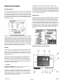
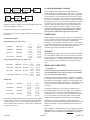
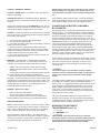
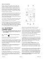
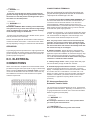
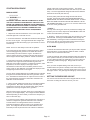
The WINPOWER alpha-numerical numbering system consists of a
base model designation, followed by an options section, separated
by a dash mark. The base component of the model numbering
system identifies an engine type, engine starting method, fuel type,
kilowatt rating, engine manufacturer, and number of generator poles.
Following the separation dash mark is the voltage connection and
optional installed equipment. Options include features like weather
enclosures (housing), and trailer options.
Please note that some features or packages, such as NFPA level
I & II, do not have an indication place in this numbering system.
They are issued and built with an M-Spec (i.e. M-10372) number
which can be found on the WINPOWER data tag. When the MSpec is present, supplemental inserts will accompany this
standard manual providing information about the special equipment and features installed. The standard model numbering key
that can be used along with the data tag information and/or Mspec supplements to determine the generator sets ratings and
specifications
The engine generator set consists of a multi-cylinder, liquid cooled
engine nominally operating at 1800 rpm. The generator frequency
regulation is maintained by the engine governor to within +/- 1.5 hertz
(cps), from no load to rated load for standard mechanical governors
and to within +/- .5 hertz or better for units equipped with an electronic
governor. The generator is a single bearing, direct drive, rotating
field design. The generator is connected to the engine flywheel via
flexible drive disks. The Generator Set is skid mounted with isolation
mounts between the engine and base on all units.
Unit Orientation Note: All references used in this manual for unit
familiarization, access and component locations on the Generator
Set are oriented from a TOP (plan) VIEW with engine at the FRONT
and generator to the REAR.
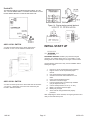
WINPOWER uses a common junction box for all customer control
and power connections (both AC output and DC control). The
common electrical junction box is always on the left side at the
generator end of the machine.
A customer supplied 12 (or 24) Volt battery is required to complete
the installation.
The engine is controlled and Generator Set operation is monitored
for safe operation by a programmable microprocessor based Electronic Engine Control Module (ECM) with an LCD digital display. The
Generator Set ECM control is mounted on a vertical pedestal on the
right side of the generator. The ECM is programmed with a cycle
cranking sequence - 3 cycles of 15 seconds on / 15 seconds off, and
a 5 minute cool down delay. The cool down delay can be changed
in the field from 0 to 30 minutes by your dealer. Other features, timing
cycles, set points and signal output capabilities are possible. Consult factory for procedure and passwords.
1285-00
Page 2
MODEL NUMBERING SYSTEM
BUILD YOUR GENSET REQUIREMENT FROM
THE BOTTOM OF THE PAGE TO THE TOP
G R N 20 I 4 - A H M T
Rated output of generators is based on engineering tests of
typical units, and is subject to, and limited by, the temperature,
altitude, fuel, and other conditions specified by the manufacturer
of the applicable engines.
TRAILER OPTION
IF PRESENT UNIT IS MOUNTED ON A
TRAILER WITH FUEL TANK FUEL. TANK SIZES SHOWN BY
PREVOUIS LETTER (SMALL AND MEDUIM FUEL TANKS ONLY)
FUEL TANK SIZE
S = SMALL
L = LARGE
SEE CURRENT PRICE SHEET
TO DETERMINE CAPACITY
M = MEDUIM
* = NONE
HOUSING TYPE
H = WEATHER HOUSING (WEATHER-PAK) * = NO HOUSING
A = SOUND ATTENUATED/WEATHER PROTECTIVE (SOUND-PAK)
VOLTAGE
A = SINGLE PHASE 120/240
J = THREE PHASE 120/240
D = THREE PHASE 120/208
L = THREE PHASE 277/480
BASE UNIT - OPTIONS SEPARATOR
NUMBER OF POLES ON THE GENERATOR
4 POLES STANDARD
ENGINE MANUFACTURE
V = VOLVO
I = ISUZU (10 & 20 kW)
D = DEUTZ
I = IVECO (ALL OTHERS)
KILOWATTS
G = GM
N = NG ENGINES
GENERATOR OUTPUT IN KILOWATTS WITH STANDBY
GASEOUS FUEL TYPE
N = NATURAL GAS
P = LIQUID PROPANE VAPOR
L = L/P LIQUID WITHDRAWL
NOT USED WITH DIESEL FUEL
STARTING METHOD
R - REMOTE STARTING
FUEL TYPE
D = DIESEL
G = GASEOUS
60708-153