1
INSTALLATION AND OPERATION INSTRUCTIONS
MODEL: SL-550TRSI-AUE
AUSTRALIAN GAS ASSOCIATION CERTIFIED
CERTIFICATE NUMBER 5666
THIS MANUAL MUST BE USED FOR INSTALLATION AND RETAINED
BY HOMEOWNER FOR OPERATION AND MAINTENANCE.
HEAT & GLO, a brand of Hearth & Home Technologies Inc.
20802 Kensington Boulevard, Lakeville, MN 55044, USA, www.heatnglo.com
THIS PRODUCT MAY BE COVERED BY ONE OR MORE OF THE FOLLOWING PATENTS:
(United States) 4593510, 4686807, 4766876, 4793322, 4811534, 5000162, 5016609, 5076254, 5113843, 5191877, 5218953, 5263471, 5328356, 5341794, 5347983, 5429495,
5452708, 5542407, 5601073, 5613487, 5647340, 5688568, 5762062, 5775408, 5890485, 5931661, 5941237, 5947112, 5996575, 6006743, 6019099, 6048195, 6053165, 6145502,
6170481, 6237588, 6296474, 6374822, 6413079, 6439226, 6484712, 6543698, 6550687, 6601579, 6672860, 6688302B2, 6715724B2, 6729551, 6736133, 6748940, 6748942, D320652,
D445174, D462436; (Canada) 1297749, 2195264, 2225408; (Australia) 543790;586383; (Mexico) 97-0457; (New Zealand) 200265; or other U.S. and foreign patents pending.
Heat & Glo • SL-550TRSI-AUE • 2079-902 Rev. K • 10/08
1
PLEASE READ THIS MANUAL BEFORE INSTALLING
AND USING THIS APPLIANCE.
MODEL SL-550TRSI-AUE
IS AUSTRALIAN GAS ASSOCIATION
APPROVED FOR NATURAL GAS OR
PROPANE AS A BALANCED FLUE
HEATER.
Refer to the appliance data plates for gas
consumptions and pressures.
Installation of this appliance should only be
carried out by an authorized person in accordance with the manufacturer's instructions. Appliance is to be installed in full
compliance with the National Gas Installation Standard AS5601, the manufacturer's
instructions, and any local authorities' requirements for gas, electrical and building
regulations.
This appliance and its components are
tested and safe when installed in accordance with this Installation Manual. Report
to your dealer any parts damaged in shipment, specifically check glass condition.
The gas logs and flue system components
are in separate packages. Read all instructions before starting installation and
follow these instructions carefully during
installation to ensure maximum benefit and
safety. Failure to follow them will void your
warranty and may present a fire hazard.
The Heat & Glo, a brand of Hearth & Home
Technologies Inc. warranty will be voided
by, and Heat & Glo, a brand of Hearth &
Home Technologies Inc. disclaims any responsibility for the following actions:
• Installation of any damaged heater or
flue system component
• Modification of the heater or balanced
flue system installation other than as
instructed by Heat & Glo, a brand of
Hearth & Home Technologies Inc.
• Improper positioning of the gas logs or
the glass door
• Installation and/or use of any component
part not manufactured or approved by
Heat & Glo, brand of Hearth & Home
Technologies Inc., not withstanding any
independent testing laboratory or other
party approval of such component part
or accessory.
IMPORTANT: Read all instructions carefully before starting installation.
Failure to follow these installation instructions may result in a possible fire
hazard and will void the warranty. Save this manual for future reference.
Heat & Glo, a brand of Hearth & Home Technologies, Inc.
20802 Kensington Blvd., Lakeville, MN 55044, USA
Copyright 2008 • Printed in U.S.A.
2
Heat & Glo • SL-550TRSI-AUE • 2079-902 Rev. K • 10/08
TABLE OF CONTENTS
1.0 Installation Instructions .......................................................................................5
1.1 Introduction ...................................................................................................6
1.2 Flue System Approvals and Installation ........................................................8
1.3 Connecting the Gas Supply ........................................................................23
1.4 Ignition System Wiring ................................................................................24
1.5 Blower ........................................................................................................25
1.6 Finishing .....................................................................................................26
1.7 Installer Testing ...........................................................................................27
1.8 Log Placement ............................................................................................28
2.0 Operating Instructions .......................................................................................31
2.1 Safety and Lighting Information ..................................................................32
2.2 Power Outage.............................................................................................33
2.3 Fan Operation .............................................................................................33
3.0 Servicing and Maintenance ...............................................................................33
3.1 Removal of Covers for Servicing ................................................................34
3.2 Removal of Components for Service ..........................................................34
3.3 Parts Replacement .....................................................................................34
3.4 Adjustments and Replacement Parts .........................................................34
3.5 Maintenance Tasks .....................................................................................35
3.6 Troubleshooting ..........................................................................................36
4.0 Replacement Parts ...........................................................................................37
Limited Warranty ...............................................................................................40
Î = Contains updated information.
Heat & Glo • SL-550TRSI-AUE • 2079-902 Rev. K • 10/08
3
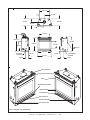
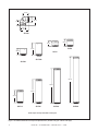
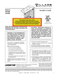
653 mm
327 mm
402 mm
414 mm
223 mm
168 mm
671mm
1035 mm
877 mm
816 mm
408 mm
593 mm
203 mm
790 mm
GAS LINE
ACCESS
93 mm
58 mm
913 mm
178 mm
153 mm
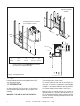
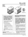
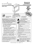
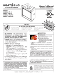
TOP STANDOFFS
FLUE COLLAR COVER PLATE
HOOD
DATA BADGE & LABELS
DRESS GUARD
ACCESS DOOR
GAS CONTROLS
ELECTRIC ACCESS
GAS LINE ACCESS
Figure 1. Diagram of SL-550TRSI-AUE
4
ELECTRICAL
ACCESS
Heat & Glo • SL-550TRSI-AUE • 2079-902 Rev. K • 10/08
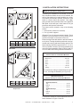
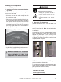
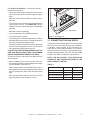
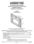
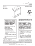
1.0 INSTALLATION INSTRUCTIONS
Top Flue
NOTE: Not intended for heater insert.
25 mm MIN.
In planning the installation for the heater it is necessary to determine where the unit is to be installed, the
type of flue system to be used (straight out, corner,
or elevated), and whether optional accessories (wall
switch or remote control) are desired. Gas supply
piping should also be planned. Refer to the appliance
data plate on the base pan of the heater for all gas
pressures and input rate information.
B
A
The heater can be mounted on any of the following
surface:
E
D
1. A flat surface (minimum 6 mm base).
2. Four (4) corner supports.
(Example: Four (4) concrete masonry blocks). These
supports must be positioned so they contact all four
(4) perimeter edges on the bottom of the unit.
C
12.5 mm MIN.
Millimeter
A
B
C
D
E
940
413
749
1070
1511
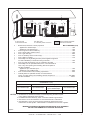
Heater framing can be built before or after the heater is
set in place. Framing should be positioned to accommodate wall covering and heater facing material. The
heater framing should be constructed of 2" X 4" (51 x
102 mm) lumber or heavier. The framing headers may
rest on the heater standoffs. Refer to Figure 2 and Figure 4 for heater and framing reference dimensions.
Rear Flue
76 mm MIN.
Minimum Clearances
from the Heater to Combustible Materials
B
Glass Front ........................................ 914 mm
Floor ....................................................... 0 mm
Rear ...................................................... 13 mm
Sides..................................................... 13 mm
Top ....................................................... 86 mm
Ceiling* ............................................... 787 mm
A
E
D
*The clearance to ceiling is measured from the top of
the unit, excluding the standoffs (see Figure 30).
C
Minimum Clearances
from the Vent Pipe to Combustible Materials
76 mm MIN.
Vertical Sections .................................25 mm
Millimeter
A
B
C
D
E
940
413
889
1219
1803
Figure 2. Heater Dimensions, Locations, and Space
Requirements
Horizontal Sections
Top ........................................................75 mm
Bottom ..................................................25 mm
Sides.....................................................25 mm
At Wall Firestops
Top ........................................................75 mm
Bottom ..................................................25 mm
Sides.....................................................25 mm
For minimum clearances, see the balanced flue termination clearance in Figure 23 and 28.
Heat & Glo • SL-550TRSI-AUE • 2079-902 Rev. K • 10/08
5
The framing headers
may rest on the heater
stand-offs.
Framing should be constructed
of 2 X 4 lumber or heavier.
B
A
FLUE
FRAMING
HOLE
C
76 mm
WALL STUD
D
E
86 mm
A
940 mm
B
883 mm
C
420 mm
D*
1035 mm
E*
593 mm
*NOTE: This dimension is to the center of the flue pipe. The
center of the framing hole MUST BE 25.4 mm above
the center of the horizontal flue pipe.
Figure 3. Framing Dimensions
CAUTION: Measure heater dimensions, and verify
framing methods and wall covering details before framing construction begins.
1.1 INTRODUCTION
This model is designed to operate with all combustion
air being siphoned from the outside of the building
and all exhaust gases expelled to the outside of the
building.
WARNING: THIS UNIT IS NOT FOR USE WITH
SOLID FUEL.
6
These units MUST use the flue termination described
in the flueing section of the manual.
The control system for this model is an electronic ignition type. It consists of a gas control valve/variable
regulator, a pilot/sensor/electrode and an ON/OFF
switch. The controls are located behind the access
door. Rotate the door down to open. See Figure 1.
Minimum inlet gas supply pressure for purpose of
input adjustment is 1.13 kPa for natural gas and 2.75
kPa for propane. Manifold (outlet) pressures should
be set at .8 kPa for natural gas models and 2.36 kPa
for propane models.
Heat & Glo • SL-550TRSI-AUE • 2079-902 Rev. K • 10/08
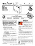
a
j
c
e
j
e
d
See note 3
openable
window
h
door
n
P
h
g
M
T
k
f
c
T
h
j
d
I
b
g
T
k
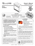
See note 2
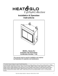
T = Flue terminal
I = Mechanical air inlet
a
-
b
c
d
e
f
g
-
h
j
-
k
n
-
M = Gas meter
P = Electricity meter or fuse box
Shading indicates prohibited
areas for flue terminals
Below eaves, balconies or other projections:
MIN. CLEARANCE (mm)
Appliances to 50 MJ/h input ...................................................................................................300
Appliances over 50 MJ/h input ...............................................................................................500
From the ground or above a balcony .........................................................................................300
From a return wall or external corner.........................................................................................500
From a gas meter (M) ..............................................................................................................1000
From an electricity meter or fuse box (P)...................................................................................500
From a drain or soil pipe ............................................................................................................150
Horizontally from any building structure (unless appliance approved
for closer installation) or obstruction facing a terminal...............................................................500
From any other flue terminal, cowl, or combustion air intake ....................................................500
Horizontally from an openable window, door, non-mechanical air
inlet, or any other opening into a building, with the exception of
sub-floor ventilation:
Appliances up to 150 MJ/h input ............................................................................................500
Appliances over 150 MJ/h input ...........................................................................................1500
From a mechanical air inlet, including a spa blower ...............................................................1500
Vertically below an openable window, non-mechanical air
inlet or any other opening into a building, with the exception of ...................................... See table
sub-floor ventilation................................................................................................................ below
CLEARANCE 'n' (mm)
Space Heaters
All other appliances
Up to 50 MJ/h input
Up to 50 MJ/h input
Over 50 MJ/h input and
Up to 150 MJ/h input
Over 50 MJ/h input
150
500
1000
1500
NOTES: 1. All distances are measured vertically or horizontally along the wall to a point
in line with the nearest part of the terminal.
2. Prohibited area below electricity meter or fuse box extends to ground level.
3. See clause 5.13.6.6 for restrictions on a flue terminal under a roofed area.
4. See Appendix J, Figure J1(a) and J2(a) for clearances required from a flue
terminal to a LP Gas cylinder. A flue terminal is considered to be a source of ignition.
MINIMUM CLEARANCES REQUIRED FOR BALANCED FLUE TERMINALS
OR THE FLUE TERMINALS OF OUTDOOR APPLIANCES
Figure 4.
Heat & Glo • SL-550TRSI-AUE • 2079-902 Rev. K • 10/08
7
TABLE 1
FLUE TERMINATION APPROVALS
DVP-TRAP2 & SLP-TRAP2 HORIZONTAL TERMINATION CAP
DVP-TVHW & SLP-TVHW VERTICAL TERMINATION CAP
MODEL
SL-550TRSI-AUE
adhered to. The rise to run relationships are shown
in the flueing drawings and tables on the next few
pages.
1.2 FLUE SYSTEM APPROVALS
These models have flue starting collars on both the top
and the back of the unit. Depending upon the installation, decide which ONE set of starting collars will be
used to attach the flue system. The starting collar sealing cap must remain on the starting collar NOT used.
WARNING: THIS GAS APPLIANCE AND FLUE ASSEMBLY MUST FLUE DIRECTLY TO THE OUTSIDE
AND MUST NEVER BE ATTACHED TO A CHIMNEY
SERVING A SEPARATE SOLID FUEL BURNING
APPLIANCE. EACH GAS APPLIANCE MUST USE
A SEPARATE FLUE SYSTEM-COMMON FLUE SYSTEMS ARE PROHIBITED.
These models use SLP series direct flue components
when using the TOP flue collars and DVP series direct
flue components when using the REAR flue collars.
WARNING: YOU MUST NOT MIX DVP-SERIES AND
SLP SERIES COMPONENTS IN ANY FLUE SYSTEM
CONFIGURATION.
CAUTION: UNDER NO CONDITION SHOULD COMBUSTIBLE MATERIAL BE CLOSER THAN 76 MM AT
WALL FIRE-STOPS FROM THE TOP OF THE PIPE
OR 25 MM TO THE SIDES AND THE BOTTOM FOR
HORIZONTAL SECTIONS OF THIS FLUE SYSTEM.
VERTICAL SECTIONS OF THIS SYSTEM REQUIRE
A MINIMUM OF 25 MM CLEARANCE TO COMBUSTIBLE MATERIALS ALL AROUND THE PIPE.
Approved flue system components are labeled for
identification. NO OTHER FLUEING SYSTEMS OR
COMPONENTS MAY BE USED. Detailed installation
instructions are included with each flue termination kit
and should be used in conjunction with this manual.
Figure 5 below shows flue system components and
terminations.
For alternative installations, other than depicted, contact your dealer for further information.
Identifying Flue Components
The flue systems installed on this gas heater may
include one, two, or three 90° elbow assemblies. The
relationships of vertical rise to horizontal run in flue
configurations using 90° elbows MUST BE strictly
Refer to Figure 4 for required clearances to flue terminals.
VERTICAL
TERMINATION
STORM COLLAR
ROOF FLASHING
HORIZONTAL
TERMINATION
HORIZONTAL PIPE
SUPPORT
PIPE LENGTH
WALL FIRESTOP
90 DEGREE
ELBOW
Flue system termination kits
SLP SERIES
SLP-TRAP2
SLP-TVHW
CEILING
FIRESTOP
DVP SERIES
DVP-TVHW
DVP-TRAP2
Figure 5. Flue Components and Terminations
8
Heat & Glo • SL-550TRSI-AUE • 2079-902 Rev. K • 10/08
WALL BRACKET
102 mm
152 mm
305 mm
DVP4
DVP6
DVP12
362 mm
310 mm
MAX
51 mm
MIN
610 mm
914 mm
DVP12A
1219 mm
251 mm
DVP24
45.0º
260 mm
DVP45
DVP36
286 mm
184 mm
32 mm TYP
DVP48
217 mm
13 mm TYP
319 mm
DVP90ST
NOTE: PIPES OVERLAP 32 mm AT EACH JOINT
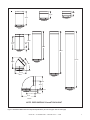
Figure 6. DVP-Series Balanced Flue Component Specifications (127 mm inner pipe / 203 mm outer pipe)
Heat & Glo • SL-550TRSI-AUE • 2079-902 Rev. K • 10/08
9
165 mm
167 mm
235 mm
152 mm
168 mm
248 mm
SLP90
184 mm
133 mm
SLP6
337 mm
184 mm
SLP4
SLP12A
SLP6A
1251 mm
946 mm
641 mm
337 mm
SLP12
SLP24
SLP36
Note: Pipes overlap 34.93 mm at each joint.
Figure 7. SLP Series Balanced Flue Component Specifications (102 mm inner pipe / 168 mm outer pipe)
10
Heat & Glo • SL-550TRSI-AUE • 2079-902 Rev. K • 10/08
SLP48
Vertical Flue Restrictor
If the heater installation requires a vertical flue
exceeding 4.5 m above the unit with no horizontal
flue or elbows, a vertical flue restrictor must be
installed (see Figure 8).
CAP
VERTICAL FLUEING
V
V
10.97 M MAXIMUM
RESTRICTOR
PLATE
USE SLP SERIES
COMPONENTS ONLY.
Figure 8.
Figure 9.
STRAIGHT OUT HORIZONTAL
FLUEING
H
Max. Run
610 mm
H
USE DVP-SERIES COMPONENTS ONLY.
Figure 10.
Heat & Glo • SL-550TRSI-AUE • 2079-902 Rev. K • 10/08
11
NOTE: A 184 mm section of vertical flue
must be attached to the heater before
a 90º elbow.
H
V
USE SLP SERIES
COMPONENTS
ONLY.
FLUEING WITH ONE (1) 90° ELBOW
V
H
FT. (M)
FT. (M)
1' MIN. (0.30 M)
2' MAX. (0.61 M)
2' MIN. (0.61 M)
4' MAX. (1.22 M)
3' MIN. (0.91 M)
8' MAX. (2.44 M)
4' MIN. (1.22 M)
10' MAX. (3.05 M)
V + H = 30' (9.14 M)
Figure 11.
FLUEING WITH ONE (1) 90º ELBOW
V (FT.)
H (FT.)
1' MIN. (0.30 M)
2' MIN. (0.61 M)
3' MIN. (0.91 M)
4' MIN. (1.22 M)
3' MAX. (0.91 M)
6' MAX. (1.83 M)
9' MAX. (2.74 M)
12' MAX. (3.66 M)
V+H =36' MAX.(10.97 M) H= 12' MAX. (3.66 M)
USE DVP-SERIES
COMPONENTS
ONLY.
V
H
Figure 12.
12
Heat & Glo • SL-550TRSI-AUE • 2079-902 Rev. K • 10/08
FLUEING WITH TWO (2) 90° ELBOWS
V
FT. (M)
1' MIN.(0.30 M)
2' MIN.(0.61 M)
3' MIN.(0.91 M)
4' MIN.(1.22 M)
5' MIN.(1.52 M)
H + H1
FT. (M)
2' MAX.(0.61 M)
4' MAX.(1.22 M)
6' MAX.(1.83 M)
8' MAX.(2.44 M)
10' MAX. (3.05 M)
30' MAX.(9.14 M)
10' MAX. (3.05 M)
H1
V
USE SLP SERIES COMPONENTS ONLY.
H
H
V1
V
FLUEING WITH TWO (2) 90° ELBOWS
V
H
FT. (M)
FT. (M)
1' MIN.(0.30 M)
2' MAX.(0.61 M)
2' MIN.(0.61 M)
4' MAX. (1.22 M)
3' MIN.(0.91 M)
6' MAX. (1.83 M)
4' MIN.(1.22 M)
8' MAX. (2.44 M)
5' MIN.(1.52 M)
12' MAX. (3.66 M)
NOTE: V + V1 MAX 33' (10.06 M)
Figure 13.
Heat & Glo • SL-550TRSI-AUE • 2079-902 Rev. K • 10/08
13
FLUEING WITH TWO (2) 90° ELBOWS
V
H
H + H1
1´ MIN. (0.30 M)
1´ MAX. (0.30 M) 2´ MAX. (0.61 M)
2´ MIN. (0.61 M)
2´ MAX. (0.61 M) 4´ MAX. (1.22 M)
3´ MIN. (0.91 M)
3´ MAX. (0.91 M) 8´ MAX. (2.44 M)
4´ MIN. (1.22 M)
4´ MAX. (1.22 M) 10´ MAX. (3.05 M)
H = 8´ MAX. (2.44 M) H + H1= 10´ MAX. (3.05 M)
V + H + H1 = 30’ (9.14 M) MAX.
H1
V
USE DVP-SERIES
COMPONENTS ONLY.
H
V (FT)
H + H1 (FT)
1' MIN. (0.30 M)
3' MAX. (0.91 M)
2' MIN. (0.61 M)
5' MAX. (1.52 M)
3' MIN. (0.91 M)
8' MAX. (2.44 M)
4' MIN. (1.22 M)
12' MAX. (3.66 M)
H + H1= 12' MAX. (3.66 M)
V + H + H1= 33' (10.06 M) MAX.
V
H1
H
Figure 14.
14
Heat & Glo • SL-550TRSI-AUE • 2079-902 Rev. K • 10/08
FLUEING WITH THREE (3) 90° ELBOWS
V
FT. (M)
2' MIN.(0.61M)
3' MIN.(0.91M)
4' MIN.(1.22M)
H
H + H1
FT. (M)
FT. (M)
2' MAX.(0.61M)
3' MAX.(0.91M)
4' MAX.(1.22M)
V+V1 = 30' MAX (9.14M)
4' MAX.(1.22M)
6' MAX (1.83M)
8' MAX.(2.44M)
H
6' MAX (1.83M) 8' MAX.(2.44M)
H1
V1
V
USE SLP SERIES COMPONENTS ONLY.
V1
V
H1
H
FLUEING WITH THREE (3) 90° ELBOWS
V
H + H1
FT. (M)
FT. (M)
1'MIN.(0.30 M)
2'MIN.(0.61 M)
3'MIN.(0.91 M)
4'MIN.(1.22 M)
5'MIN.(1.52 M)
2' MAX.(0.61 M)
4' MAX.(1.22 M)
6' MAX.(1.83 M)
8' MAX.(2.44 M)
12' MAX.(3.66 M)
12' MAX.(3.66 M)
NOTE: V + V1 MAX. 33' (10.06 M)
Figure 15.
Heat & Glo • SL-550TRSI-AUE • 2079-902 Rev. K • 10/08
15
FLUEING WITH THREE (3) 90° ELBOWS
V (FT.)
H (FT.)
1´ MIN. (0.30 M)
2´ MIN. (0.61 M)
3´ MIN. (0.91 M)
4´ MIN. (1.22 M)
H + H1 (FT.)
1´ MAX. (0.30 M)
3´ MAX. (0.91 M)
2´ MAX. (0.61 M)
5´ MAX. (1.52 M)
4´ MAX. (1.22 M)
8´ MAX. (2.44 M)
6´ MAX. (1.83 M)
12´ MAX. (3.66 M)
H = 6´ MAX. (1.83 M) H+H1 = 12´ MAX. (3.66 M)
NOTE: V + V, + H + H1 = 33’ (10.06 M) MAX.
V1
V
H
H1
USE DVP-SERIES
COMPONENTS ONLY.
H2
V
H1
V (FT.)
FLUEING WITH THREE (3) 90° ELBOWS
H (FT.)
H + H1 + H2 (FT.)
1´ MIN. (0.30 M)
2´ MIN. (0.61 M)
3´ MIN. (0.91 M)
4´ MIN. (1.22 M)
1´ MAX. (0.30 M)
2´ MAX. (0.61 M)
3´ MAX. (0.91 M)
4´ MAX. (1.22 M)
V+H+H1+H2=30´ MAX.(9.14 M) H = 4´MAX.(1.22 M)
2´ MAX. (0.61 M)
4´ MAX. (1.22 M)
8´ MAX. (2.44 M)
10´ MAX. (3.05 M)
H+H1+H2 =10´MAX.(3.05 M)
Figure 16.
16
Heat & Glo • SL-550TRSI-AUE • 2079-902 Rev. K • 10/08
H
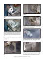
Appliance Preparation
After determining which set of starting collars will
be used (top or rear), follow flueing instructions
accordingly.
!
!
!
WARNING: FAILURE TO REMOVE INSULATION IN THE SET OF COLLARS
YOU ARE USING COULD CAUSE A
FIRE.
WARNING: YOU MUST LEAVE THE
INSULATION AND FLUE CAP IN
PLACE IN THE SET OF COLLARS
YOU ARE NOT USING.
WARNING: FIRE RISK ONCE APPLIANCE IS SETUP FOR TOP OR REAR
FLUEING, IT CANNOT BE CHANGED
AT A LATER TIME. IF FLUE CAP
AND COMPONENTS PREVIOUSLY
REMOVED ARE IMPROPERLY REINSTALLED, A FIRE MAY RESULT.
Figure 18. Rotate the top heat shield to the vertical
position as shown above. The heat shield must remain
in the vertical position.
2 SCREWS
Figure 19. Replace the two screws as shown.
CAUTION
Sharp edges-Wear protective gloves and safety glasses
during installation.
Top Flue
2 SCREWS
Figure 20. Remove the flue cap.
Figure 17. For top flue, remove the two screws holding the top heat shield in place. For rear flue, see
next page.
!
WARNING: FIRE RISK DO NOT REMOVE HEAT SHIELD. ELEVATED
HEADER TEMPERATURES MAY
CAUSE A FIRE.
Figure 21. Remove the insulation basket and white
insulation from the center flue pipe.
Heat & Glo • SL-550TRSI-AUE • 2079-902 Rev. K • 10/08
17
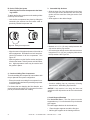
Figure 25. Cut the metal retaining band and fold the
sides out.
Figure 22. Remove the insulation from the outer flue
pipe.
Figure 26. Fold the center parts of the retaining band
out and us to remove the flue cap.
2 SCREWS
Figure 23. To attach the first section of flue pipe, make
sure to use the fiberglass gasket to seal between the
first vent component and the outer heater wrap. Use
2 self tapping screws to secure the gasket to the outer
wrap.
Note: Once the flue cap has been removed, it cannot
be reattached.
Rear Flue
Figure 27. Discard the flue cap, remove and discard
the insulation basket. Note: Once the flue cap has
been removed it CANNOT be reattached.
Figure 24. Remove the insulation from the outer flue
pipe.
Figure 28. Attach the first flue section (it will snap into
place). Slide the insulation gasket onto the flue section,
up against the appliance and over the tabs. Use two
self-tapping screws to secure gasket to outer wrap.
18
Heat & Glo • SL-550TRSI-AUE • 2079-902 Rev. K • 10/08
Installing Flue Components
WARNING
A. On the REAR of the heater
Fire Risk
Exhaust Fumes Risk
Impaired Performance of Appliance
• Overlap pipe slip sections at least 38
mm.
• Screws must not exceed one inch
long.
• Pipe may separate if not properly
joined.
1. Attaching the First Flue Component to the Starting Collars:
To attach the first flue component to the starting collars
on the rear of the heater:
• Make sure that the flue gasket supplied with the
heater seals between the first flue component and
the outer heater wrap.
• Slide the male end of the inner flue of the pipe section over the inner collar on the heater. At the same
time, slide the outer flue over the outer collar on the
heater. Push the flue section into the appliance collar
until all the lances (see Figure 29) have snapped in
place. Tug slightly on the flue to confirm that it has
completely locked into place.
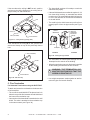
2. Assembling Flue Components
Insert the inner flue of section A into the flared inner
flue of section B.
Start the outer flue of section A over the outer flue of
section B (see Figure 30). Note: The end of the pipe
sections with the lances/tabs on it will face towards
the appliance.
Once both inner and outer flues are started, press
section A onto section B firmly until all lances have
snapped into place. Check to make sure they have
snapped together (see Figure 31) and the seams are
not aligned. Tug slightly on section A to confirm it has
completely locked into place.
Figure 29.
A
• Any 90º elbow installed directly onto the rear flue of
the heater MUST BE in a vertical position.
!
WARNING: ENSURE THAT THE HEATER
GASKET SUPPLIED WITH THE HEATER
SEALS BETWEEN THE FIRST FLUE
COMPONENT AND THE OUTER HEATER
WRAP.
B
Figure 30.
Figure 31.
NOTE: Make sure that seams are NOT aligned to
prevent unintentional disconnection.
For elbows that are changing the flue direction, two
screws minimum should be put in the outer flue at the
joint to prevent the elbow from rotating.
PROCEED TO STEP 4
(Install Support Brackets)
Heat & Glo • SL-550TRSI-AUE • 2079-902 Rev. K • 10/08
19
B. On the TOP of the heater
3. Assemble Slip Sections
1. Attaching the First Flue Component to the Starting Collars:
• Slide the inner flue of the slip section into the inner
flue of the pipe section and the outer flue of the slip
section over the outer flue of the pipe section. See
Figure 33.
To attach the first flue component to the starting collars
on the top of the heater:
• Lock the flue components into place by sliding the
concentric pipe sections into the heater collar or
previously installed component end.
• Slide together to the desired length.
Pilot hole
Figure 33. Slip Section Pilot Holes
Figure 32. Adding Flue Components
• Align the seam of the pipe and seam of the collar to
allow engagement. Rotat the flue to lock into place.
Use this procedure for all the components. See
Figure 32.
• Maintain a 1-1/2 in. (38 mm) overlap between the
slip section and the pipe section.
• Secure the pipe and slip section with two screws no
longer than 1/2 in. (13 mm), using the pilot holes in
the slip section. See Figure 34.
• Slide the gasket over the first flue section and place
it flush to the heater. This will prevent cold air infiltration. High temperature caulk may be used to hold
the gasket in platce.
2. Continue Adding Flue Components
To continue adding flue components in accordance with
the pre-planned flue system configuration:
• Ensure that each succeeding flue component is securely fitted and locked into the preceding component
in the flue system.
For elbows that are changing the flue direction, two
screws minimum should be put in the outer flue at the
joint to prevent the elbow from rotating.
Figure 34. Screws into Slip Section
• Continue adding pipe as necessary following
instructions in “Assembling Pipe Sections.”
NOTICE: If slip section is too long, the inner and
outer flues of the slip section can be cut to the desired
length.
4. Install Support Brackets
For Horizontal Runs - The flue system must be
supported every 1.5 m of horizontal run by a horizontal
pipe support.
To install support brackets for horizontal runs:
•
Place the pipe supports around the flue pipe.
• Nail the pipe supports to the framing members.
20
Heat & Glo • SL-550TRSI-AUE • 2079-902 Rev. K • 10/08
For Vertical Runs
The flue system must be supported every 2.4 M above
the heater flue outlet by wall brackets.
To install support brackets for vertical runs:
• Attach wall brackets to the flue pipe and secure the
wall bracket to the framing members with nails or
screws.
WALL BRACKET
For Vertical Runs - One firestop is REQUIRED at the
hole in each ceiling through which the flue passes.
To install firestops for vertical runs that pass through
ceilings:
•
Position a plumb bob directly over the center of the
vertical flue component.
•
Mark the ceiling to establish the centerpoint of the
flue.
•
Drill a hole or drive a nail through this center
point.
•
Check the floor above for any obstructions, such
as wiring or plumbing runs.
•
Reposition the heater and flue system, if necessary,
to accommodate the ceiling joists and/or obstructions.
•
Cut a 254 mm X 254 mm hole through the ceiling
when using DVP pipe, and a 229 mm x 229 mm
hole when using SLP pipe. Use the firestop pipe
opening as a guide.
•
Frame the hole with framing lumber the same size
as the ceiling joists.
WALL STUD
2.4m
FLUE
OUTLET
A
B
CHIMNEY
HOLE
25 mm
NEW
FRAMING
MEMBERS
Figure 35. Installing Support Brackets
EXISTING CEILING
JOISTS
CEILING
4. Install Firestops
For Horizontal Runs - Firestops are REQUIRED on
both sides of a combustible wall through which the
flue passes.
Frame a hole in a combustible wall for an interior wall
shield firestop, whenever a wall is penetrated. Use
same size framing materials as those used in the wall
construction. The wall shield firestop maintains minimum clearances and prevents cold air infiltration. a
wall shied firestop must be placed on each side of an
interior wall. A minimum 38 mm overlap of attached
heat shield must be maintained. See Figure 35.
A
B
SLP
229 mm
229 mm
DVP
254 mm
254 mm
Figure 36. Hole and New Framing Members
Non-Combustible Wall Penetration
If the hole being penetrated is surrounded by noncombustible materials such as concrete, a hole with
diameter 25.4 mm greater than the pipe is acceptable.
Whenever a non-combustible wall is penetrated, the
wall shield firestop is only required on one side and no
heat shield is necessary.
Heat & Glo • SL-550TRSI-AUE • 2079-902 Rev. K • 10/08
21
If the area above the ceiling is NOT an attic, position
and secure the ceiling firestop on the ceiling side of
the previously cut and framed hole.
JOIST
• The heat shield sections will overlap to match the
wall thickness (depth).
• If the wall thickness does not allow the required 1-1/2
inch heat shield overlap, an extended heat shield
must be used. The extended heat shield will need to
be cut to the thickness of the wall and be attached
to the wall shield.
• The small leg in the shield rests on top of the flue to
properly space it from the pipe section (see Figure
39).
Interior
Wall Shield
CEILING
NAILS (4 REQUIRED)
Rear Flue
Heat Shield
38 mm min.
overlap
CEILING FIRESTOP
Figure 37. Ceiling Firestop (Ceiling Side)
If the area above the ceiling IS an attic, position and
secure the firestop on top of the previously framed
hole.
Outer Flue
Inner Flue
INTERIOR
NAILS (4 REQUIRED)
EXTERIOR
Figure 39. Venting through the Wall
RAFTER
• The termination kit should pass through the wall
firestops from the exterior of the building.
• Adjust the termination cap to its final exterior position
on the building and interlock the flue sections.
!
CEILING
CEILING FIRESTOP
Figure 38. Attic Firestop
WARNING: THE TERMINATION CAP
MUST BE POSITIONED SO THAT THE
ARROW IS POINTING UP.
• Use a high-temperature sealant gasket to seal between the pipe and exterior firestop.
C. Flue Termination
For Horizontal Terminations using the DVP-TRAP
To attach and secure the termination to the last section
of horizontal flue:
• The rear flue heat shield MUST be placed one inch
above the top of the flue between the wall shield and
the base of the termination cap.
• One section of the heat shield is attached to the wall
shield. The other is attached to the termination cap
in the same manner (see Figure 39).
22
Heat & Glo • SL-550TRSI-AUE • 2079-902 Rev. K • 10/08
For Vertical Terminations - To locate the flue and
install the flue sections:
• Locate and mark the flue centerpoint on the underside of the roof, and drive a nail through the centerpoint.
• Make the outline of the roof hole around the centerpoint nail.
• The size of the roof hole framing dimensions depend
on the pitch of the roof. There MUST BE a 25 mm
clearance from the vertical flue pipe to combustible
materials.
GAS ACCESS
• Mark the roof hole accordingly.
• Cover the opening of the installed flue pipes.
• Cut and frame the roof hole.
Figure 40. Gas Supply Line
• Use framing lumber the same size as the roof rafters
and install the frame securely. Flashing anchored to
the frame must withstand heavy winds.
• Continue to install concentric flue sections up through
the roof hole and up past the roof line until you reach
the appropriate distance above the roof.
CAUTION: FOLLOW THE REQUIREMENTS OF THE
AGA GAS INSTALLATION CODE FOR MINIMUM
HEIGHT REQUIREMENTS ABOVE THE ROOF.
To seal the roof hole, and to divert rain and snow from
the flue system:
• Attach a flashing to the roof using nails, and use a
non-hardening mastic around the edges of the flashing base where it meets the roof.
• Attach a storm collar over the flashing joint to form a
water-tight seal. Place non-hardening mastic around
the joint, between the storm collar and the vertical
pipe.
• Slide the termination cap over the end of the flue
pipe and rotate the pipe clockwise 1/4 turn.
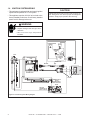
1.3 CONNECTING THE GAS SUPPLY
The gas is introduced to the appliance on the left hand
side (see Figure 40). After the gas pipe installation
is complete, check carefully all gas connections for
leaks with a commercially-available, non-corrosive
leak check solution. Be sure to rinse off all leak check
solution following testing. DO NOT USE AN OPEN
FLAME. See Table 1 for pressure requirements.
NOTE: THE GAS SUPPLY LINE SHOULD BE
PURGED OF ANY TRAPPED AIR PRIOR TO THE
FIRST FIRING OF THE UNIT.
TABLE 1.
Natural Gas
Propane Gas
Inlet Pressure
1.13 kPa
2.75 kPa
Outlet Pressure
.80 kPa
2.36 kPa
Max. Gas Consumption
28.0 mJ/h
26.0 mJ/h
Burner Injector
2.49 mm
1.45 mm
Heat & Glo • SL-550TRSI-AUE • 2079-902 Rev. K • 10/08
23
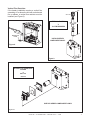
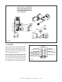
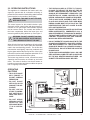
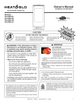
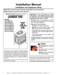
1.4
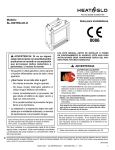
IGNITION SYSTEM WIRING
CAUTION
• This gas heater is equipped with an electronic ignition
system which operates on a 6 volt system.
Label all wires prior to disconnection when servicing controls. Wiring errors can cause improper and dangerous
operation. Verify proper operation after servicing.
• This appliance requires 240 VAC to be wired to the
factory installed junction box. Check factory installed
power cord for damage before use.
WARNING
Shock hazard.
• Replace damaged wire with type 105º C
rated wire.
• Wire must have high temperature
insulation.
FLAME SPARKER/
SENSOR
VALVE
REMOTE
CONTROL
ANT.
ON/OFF
WALL SWITCH
PILOT
IGNITION
MODULE
(6V)
IGNITION MODULE
6VDC
GROUND
HOT
NEUTRAL
BATTERY PORT
PLUG IN
THERMOCOUPLE
BLOCK
(CONNECTED TO
BACK OF VALVE)
ON/OFF
SWITCH
VALVE
GAS LINE
CONNECTED TO
BACK OF VALVE
Figure 41. Electronic Ignition Wiring Diagram
24
Heat & Glo • SL-550TRSI-AUE • 2079-902 Rev. K • 10/08
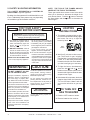
NOTE: IF ANY OF THE ORIGINAL
WIRE AS SUPPLIED WITH THE APPLIANCE MUST BE REPLACED, IT
MUST BE REPLACED WITH TYPE
105º C RATED WIRE.
BLACK
BLACK
BROWN
VARIABLE
SPEED
CONTROL
BROWN
BLUE
BLACK
BLUE
BLACK
TEMPERATURE
SENSOR SWITCH
GREEN/YELLOW
STRIPE
240VAC JUNCTION BOX
GREEN/YELLOW
STRIPE
BLUE
BROWN
BLOWER
BLUE
BROWN
GREEN/YELLOW
Figure 42.
1.5 BLOWER
These heaters have a factory installed Fan,
Electrical Junction Box, Variable Speed Rheostat Control Switch and Temperature Sensor
Switch for the fan. These components are
located behind the lower door.
BLACK
(HOT) BROWN
BROWN
BLACK
BROWN
Use of the fan requires that the Junction Box
(factory installed) be connected to 240 VAC service before permanently enclosing the heater.
The access hole for connecting the service
wires is found on the right exterior side of the
unit. See Figure 43 for wire connection detail.
(NEUTRAL) BLUE
BLUE
BLUE
Figure 43.
Heat & Glo • SL-550TRSI-AUE • 2079-902 Rev. K • 10/08
25
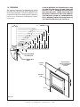
IF JOINTS BETWEEN THE FINISHED WALLS AND
THE HEATER SURROUND (TOP AND SIDES) ARE
SEALED, A 149° C. MINIMUM SEALANT MATERIAL MUST BE USED. THESE JOINTS ARE NOT
REQUIRED TO BE SEALED. ONLY NON-COMBUSTIBLE MATERIAL (USING 149° C MINIMUM ADHESIVE, IF NEEDED) CAN BE APPLIED AS FACING TO
THE HEATER SURROUND. SEE FIGURE 44.
1.6 FINISHING
The minimum clearance to combustibles are 0 from
the sides, floor, back and top (these clearances are
defined by the standoffs). The minimum distance to the
perpendicular side wall extending past the appliance
front is 51 mm. Clearance to a mantelpiece is shown
in Figure 44.
CEILING
12 mm
11 mm
10 mm
9 mm
787 mm
8 mm
178 mm
152 mm
279 mm
229 mm
127 mm
102 mm
178 mm
254 mm
76 mm
127 mm
51 mm
102 mm
76 mm
305 mm
203 mm
152 mm
51 mm
TOP FRONT EDGE
OF FIREPLACE
NON-COMBUSTIBLE
STRIP
TOP SEAL
JOINT
FINISH MATERIAL
MAY BE COMBUSTIBLE
- TOP AND SIDES
OF UNIT
SIDE SEAL
JOINT
0
13 mm
Figure 44.
26
Heat & Glo • SL-550TRSI-AUE • 2079-902 Rev. K • 10/08
Installing the Trim
Combustible materials may be brought up to the
specified clearances on the side and top front edges
of the heater, but MUST NEVER overlap onto the front
face. The joints between the finished wall and the
heater top and sides can only be sealed with a 149°
C minimum sealant.
!
WARNING: WHEN FINISHING THE HEATER, NEVER OBSTRUCT OR MODIFY THE
AIR INLET/OUTLET GRILLES IN ANY
MANNER.
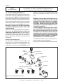
Follow the Safety Information and Lighting Instructions
pages of this manual to light the appliance.
To obtain proper operation, it is imperative that the
pilot and main burner flame characteristics are steady,
not lifting or floating. Typically, the top 10 mm of the
thermocouple should be engulfed in the pilot flame
(see Figure 45).
Proper gas log positioning is shown in Section 1.8.
Follow Section 3.5 TROUBLESHOOTING for adjusting
the appliance to operate properly.
Pilot Assembly
Install optional marble and brass trim surround kits
as desired. Marble, brass, brick, tile, or other noncombustible materials can be used to cover up the gap
between the sheet rock and the heater.
Do not obstruct or modify the air inlet/outlet grilles.
When overlapping on both sides, leave enough space
so that the bottom grille can be opened and the trim
door removed.
1.7 INSTALLER TESTING
The space heater must be tested and be operating
according to manufacturer's specifications prior to the
installer leaving the site. Note: the tips of the flames
should never hit the top of the firebox after the unit has
warmed up. Please contact your dealer or a qualified
service person to replace injector or adjust valve.
Figure 45.
Upon completing the gas line connection, a small
amount of air will be in the lines. When first lighting
the pilot light, it will take a few minutes for the lines
to purge themselves of this air. Once the purging is
complete, the pilot and burner will light and operate as
indicated in the Lighting Instructions.
Subsequent lightings of the appliance will not require
such purging.
Heat & Glo • SL-550TRSI-AUE • 2079-902 Rev. K • 10/08
27
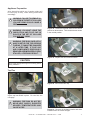
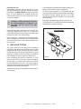
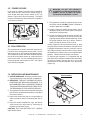
1.8 LOG PLACEMENT INSTRUCTIONS
Log Set Assembly: LOGS-550TRSI-AUE
TABS
1 2 3 4 5678
CAUTION: Logs are fragile! Carefully remove the logs from the packaging.
1
1
LOG #1 (SRV550-715): Place log #1 onto the log grate so that the notches in the bottom of the log
fit on the right three grate bars. Push log #1 towards the rear locating tabs.
2
2
LOG #2 (SRV347-703): Place log #2 so that its left edge sits against the left front grate corner and
its right edge rests against the tab on the second grate bar.
28
Heat & Glo • SL-550TRSI-AUE • 2079-902 Rev. K • 10/08
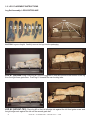
3
3
LOG #3 (SRV349-704): Position log #3 so that its right edge sits on log #1 as shown and it's left
edge sits on the first grate bar behind log #2.
4
4
LOG #4 (SRV278-705): Position log #4 between log #1 and the locating tab on the fourth grate bar.
Push its left hand side back to the locating tab as the grate bar.
5
5
LOG #5 (SRV540-704): Put the forked end of log #5 on the base in front of the grate, towards the
center of the second bar grate.
Heat & Glo • SL-550TRSI-AUE • 2079-902 Rev. K • 10/08
29
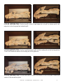
6
6
LOG #6 (SRV550-718): Place log #6 on the base on front of the grate as shown.
7
7
LOG #7 (SRV484-703): Place log #7 on the groove in log #2 with its rear top on log #1 and front
top resting on log #5.
8
8
LOG #8 (SRV347-701): Hook log #8 on the right hand corner grate bar and rest its rear on log #1
as shown.
30
Heat & Glo • SL-550TRSI-AUE • 2079-902 Rev. K • 10/08
2.0 OPERATING INSTRUCTIONS
This appliance is a balanced flue heater and is designed to operate with all combustion air being siphoned from the outside of the building and all exhaust
gases expelled to the outside of the building.
!
WARNING: THIS UNIT IS NOT FOR USE
WITH SOLID FUEL.
The control system for this model includes a pilot,
electronic module, spark ignitor and thermocouple. It
consists of a 6V gas control valve/variable regulator
and an remote control. The controls are located in
the lower compartment behind the lower door, and
access is gained by lifting the door up. See Figure 1.
!
WARNING: DO NOT CONNECT 240 VAC
TO THE GAS CONTROL VALVE OR CONTROL WIRING SYSTEM OF THIS UNIT.
When lit for the first time, the appliance will emit a slight
odor for an hour or two, due to paint and lubricants
used in the manufacturing process. For the first few
minutes after each lighting, vapor may condense and
fog the glass and the flames may be blue. After a few
minutes this moisture will disappear and within 15-30
minutes the flames should become yellow.
The heater may produce a noise, caused from metal
expansion and contraction as it heats up and cools
down. This noise is similar to one that a furnace or
heat duct may produce and does not affect the operation or longevity of the heater.
• THE DRESS GUARD IS FITTED TO THIS APPLIANCE TO REDUCE THE RISK OF FIRE OR
INJURY FROM BURNS AND NO PART OF IT
SHOULD BE PERMANENTLY REMOVED. FOR
PROTECTION OF YOUNG CHILDREN OR THE
INFIRM, A SECONDARY GUARD IS REQUIRED.
• THE GLASS DOOR ASSEMBLY MUST BE IN
PLACE AND SEALED AND THE FIXED MESH
DRESS GUARD MUST BE IN PLACE ON THE
HEATER BEFORE THE UNIT CAN BE PLACED
INTO SAFE OPERATION.
• DO NOT USE THIS APPLIANCE IF ANY PART HAS
BEEN UNDER WATER. IMMEDIATELY CALL A
QUALIFIED SERVICE TECHNICIAN TO INSPECT
THE UNIT AND TO REPLACE ANY PART OF THE
CONTROL SYSTEM AND ANY GAS CONTROL
WHICH HAS BEEN UNDERWATER.
• DO NOT OPERATE THIS APPLIANCE WITH THE
GLASS DOOR REMOVED, CRACKED, OR BROKEN. REPLACEMENT OF THE GLASS DOOR
SHOULD BE DONE BY A LICENSED OR QUALIFIED PERSON. DO NOT STRIKE OR SLAM THE
GLASS DOOR.
• THE GLASS DOOR ASSEMBLY SHALL ONLY BE
REPLACED AS A COMPLETE UNIT AS SUPPLIED
BY THE GAS HEATER MANUFACTURER. NO
SUBSTITUTE MATERIALS MAY BE USED.
OPERATING
CAUTIONS
• THIS APPLIANCE
MAY EXHIBIT A
SLIGHT CARBON
DEPOSITION.
FLAME SPARKER/
SENSOR
VALVE
REMOTE
CONTROL
ANT.
ON/OFF
WALL SWITCH
PILOT
• DO NOT PLACE
ARTICLES ON OR
AGAINST THIS APPLIANCE.
IGNITION
MODULE
(6V)
IGNITION MODULE
6VDC
GROUND
HOT
NEUTRAL
• DO NOT USE OR
STORE FLAMMABLE MATERIALS
NEAR THIS APPLIANCE.
BATTERY PORT
PLUG IN
• D O N O T S P R AY
AEROSOLS IN THE
VICINITY OF THIS
APPLIANCE WHILE
IT IS IN OPERATION.
THERMOCOUPLE
BLOCK
(CONNECTED TO
BACK OF VALVE)
ON/OFF
SWITCH
VALVE
GAS LINE
CONNECTED TO
BACK OF VALVE
Figure 46.
Heat & Glo • SL-550TRSI-AUE • 2079-902 Rev. K • 10/08
31
2.1 SAFETY & LIGHTING INFORMATION
Follow SAFETY INFORMATION and LIGHTING INSTRUCTIONS to light the appliance.
By design, the flame pattern will not be identical from unit
to unit. Additionally, flame pattern may vary depending
on installation type and weather conditions.
NOTE: THE TIPS OF THE FLAMES SHOULD
NEVER HIT THE TOP OF THE FIREBOX.
These gas models have remote control valve which
allow you to increase or decrease the height of the
button to increase
main burner flames. Push the
the flame height and the
button to decrease the
flame height.
FOR YOUR SAFETY
READ BEFORE LIGHTING
WARNING: If you do not follow these instructions
exactly, a fire or explosion may result causing property
damage, personal injury or loss of life.
A. This heater is equipped with an • Do not touch any electric switch; do
electronic pilot ignition device
not use any phone in your building.
which automatically lights the • Immediately call your gas supplier
burner. Do not try to light the
from a neighbor’s phone. Follow the
burner by hand.
gas supplier’s instructions.
B. BEFORE LIGHTING, smell all • If you cannot reach your gas
around the heater area for gas.
supplier, call the fire department.
Be sure to smell next to the floor C. Do not use this heater if any part
because some gas is heavier than
has been under water. Immediately
air and will settle on the floor.
call a qualified service technician to
WHAT TO DO IF YOU SMELL GAS
inspect the heater and to replace
any part of the control system and
• Do not try to light any appliance.
any gas control which has been
under water.
WARNING:
CAUTION:
DO NOT CONNECT 240 VAC
TO THE CONTROL VALVE.
Hot while in operation. Do not touch.
Keep children, clothing, furniture,
gasoline and other liquids having
flammable vapors away.
Improper installation, adjustment,
alteration, service or maintenance
can cause injury or property damage. Refer to the owner’s information
manual provided with this heater.
This heater needs fresh air for safe
operation and must be installed so
there are provisions for adequate
combustion and ventilation air.
If not installed, operated, and maintained in accordance with the manufacturer’s instructions, this product
could expose you to substances in
fuel or fuel combustion.
LIGHTING
INSTRUCTIONS
1. This heater is equipped with an ignition device which automatically lights
the burner. Do not try to light the
burner by hand.
GAS
VALVE
2. Wait five (5) minutes to clear out any
gas. Then smell for gas, including
near the floor. If you smell gas, STOP!
Follow “B” in the Safety Information
located on the left side of this label. If
you don’t smell gas, go to next step.
3. To light the burner, simultaneously
press the star
and up
arrow
buttons on the remote control until a
short acoustic signal confirms the start
sequence has begun.
Do not operate the heater with
panel(s) removed, cracked or broken. Replacement of the panel (s)
should be done by a licensed or
qualified service person.
4. If the heater will not operate, check the
batteries then follow the instructions
“To Turn Off Gas to Heater” and call
your service technician or gas supplier.
NOT FOR USE
WITH SOLID FUEL
TO TURN OFF
GAS TO HEATER
For use with natural, propane and
butane gases.
1. Push the ‘OFF’ button on remote.
2. Remove batteries from receiver.
Keep burner and control compartment clean. See installation and
operating instructions accompanying heater.
32
Heat & Glo • SL-550TRSI-AUE • 2079-902 Rev. K • 10/08
2.2 POWER OUTAGE
In the event of a power interruption during operation,
either push the OFF button on the remote control or
open access door and push the switch to OFF (as
shown in Figure 48) to shut off manually. The switch
must be returned to the ON position prior to operation
once power is restored.
!
WARNING: DO NOT USE ABRASIVE
CLEANERS ON THE GLASS DOOR ASSEMBLY. DO NOT ATTEMPT TO CLEAN
THE GLASS DOOR WHEN IT IS HOT.
F. The glass door should be cleaned using a household glass cleaner. DO NOT handle or attempt to
clean the glass when it is HOT.
G. Visually inspect the flexible power supply cord; if
damaged, contact the service agent for a special
replacement cord assembly.
Figure 47.
SWITCH IS SHOWN
IN “ON” POSITION
2.3 FAN OPERATION
The accessory fan is wired in series with a speed control switch and a temperature sensor switch. Set the
speed control to an "ON" position and light the heater.
The temperature sensor switch will automatically start
the fan when the switch warms up—and stop the fan
when it cools down. You can manually stop the fan by
turning the speed control switch to "OFF". See Figure
42 for fan wiring diagram.
H. In order to properly clean the burner and pilot assembly, turn off the gas to the unit and remove the
logs exposing the burner and pilot assembly. Clean
all foreign materials from top of burner. Check to
make sure that the burner orifice is clean.
Visually inspect the pilot periodically. Brush or blow
away any dust or linen accumulations. If the pilot orifice
is plugged, disassembly may be required to remove
any foreign materials from the orifice or tubing. When
the appliance is put back in service, check burner flame
patterns. Flames should be steady, not floating.
To obtain proper operation, it is imperative that the
pilot and main burner flame characteristics are steady,
not lifting or floating. Typically, the top 10 mm of the
thermocouple should be engulfed in the pilot flame
(Figure 49).
3.0 SERVICING AND MAINTENANCE
Pilot Assembly
A. HEATER SERVICING: Frequency of heater servicing will depend upon use and type of installation.
B. IMPORTANT: TURN OFF GAS AND ELECTRICAL
POWER BEFORE SERVICING APPLIANCE. IT IS
RECOMMENDED THAT A COMPETENT SERVICE
TECHNICIAN PERFORM SERVICE CHECK-UPS AT
THE BEGINNING OF EACH HEATING SEASON.
C. The appliance and flue system should be inspected
before initial use and at least annually by a qualified
field service person.
D. Inspect the external flue cap on a regular basis to
make sure that no debris is interfering with the air
flow.
E. Keep the control compartment, logs, and burner
area surround the logs clean by vacuuming or
brushing at least twice a year.
Figure 48.
CAUTION: THE LOGS GET VERY HOT - HANDLE
ONLY WHEN COOL.
Heat & Glo • SL-550TRSI-AUE • 2079-902 Rev. K • 10/08
33
3.1 REMOVAL OF COVERS FOR SERVICING
A. Control Compartment Door
• Rotate the lower door down to access the gas controls.
B. Dress Guard and Glass Door
• Lift the front dress guard up and out away from the
appliance side surrounds. Replace the dress guard
when servicing is complete.
• Release the four glass clips around the glass door.
Carefully lift the glass up and out away from the appliance (see Figure 49).
2. PILOT ASSEMBLY/IGNITION SYSTEM
• Remove the log set, log grate, metal base pan and
burner.
• Disconnect the gas supply tube from the underside
of the gas valve and the thermocouple from the interruptor block.
• Disconnect and remove the pilot assembly from the
bracket.
NOTE: When removing the pilot assembly, carefully
pull the electrode wire, detach from the assembly and
leave in place for reconnection.
3.3 PARTS REPLACEMENT
1. FAN/SWITCHES
• Disconnect the fan wires from the junction box wires
by pulling the male and female connectors apart
and slide the fan out the front of the lower controls
compartment.
• Disconnect the wires from the fan speed control
switch, pull off the knob, and remove the nut holding
the speed control to the bracket.
LATCHES
(BOTH TOP
AND BOTTOM)
GLASS
ASSEMBLY
• Disconnect the wires from the fan temperature sensor switch and remove the nut holding the switch
bracket onto the side of the firebox.
Figure 49. Glass Assembly
2. GLASS PANEL
3.2 REMOVAL OF COMPONENTS FOR
SERVICE
1. BURNER
• Carefully remove the log set. Remove the rear
screws holding the log grate. Remove log grate and
metal base pan.
• Unscrew the brackets at both ends of the burner and
the retaining screws at the pilot bracket (see Figure
50). Slide the burner towards the right away from the
burner orifice.
• To replace the glass door, place the bottom edge
on top of the bottom mounting brackets. Push glass
against unit and latch the two fasteners at the top of
the glass door and the two fasteners at the bottom
(see Figure 49).
3.4 ADJUSTMENTS AND REPLACEMENT
PARTS
Adjustments and replacement parts for this appliance
should only be done by a qualified service person. A
wiring diagram for the appliance is shown in SECTION
2.0 OPERATING INSTRUCTIONS. A replacement part
table is shown in SECTION 4.0 of this manual.
PILOT BRACKET
RETAINING SCREWS
Figure 50.
CAUTION: ALL SCREWS WHICH WERE REMOVED MUST BE REPLACED.
Heat & Glo • SL-550TRSI-AUE • 2079-902 Rev. K • 10/08
34
3.5 MAINTENANCE TASKS
Inspect
Doors
Maintenance Tasks
1. Inspect for scratches, dents or other damage and repair as necessary.
2. Verify no obstructions to airflow.
3. Verify maintenance of proper clearance to combustible household objects.
Gasket Seal, Glass
Assembly and Glass
1. Inspect gasket seal and its condition.
2. Inspect glass panels for scratches and nicks that can lead to breakage when exposed to heat.
3. Confirm there is no damage to glass or glass frame. Replace as necessary.
4. Verify that latches engage properly, clip studs are not stripped, and glass attachment components
are intact and operating properly. Replace as necessary.
5. Clean glass. Replace glass assembly if severely coated with silicate deposits that cannot be removed.
Valve Compartment
and Firebox Top
1. Vacuum and wipe out dust, cobwebs, debris or pet hair. Use caution when cleaning these areas.
Screw tips that have penetrated the sheet metal are sharp and should be avoided.
2. Remove any foreign objects.
3. Verify unobstructed air circulation.
Logs
1. Inspect for broken, damaged, or missing logs. Replace as necessary.
2. Verify correct log placement and no flame impingement causing sooting. Correct as necessary.
Firebox
1. Inspect for paint condition, warpage, corrosion or perforation. Sand and repaint as necessary.
Burner Ignition and
Operation
1. Verify burner is properly secured and aligned with pilot or igniter.
2. Clean off burner top, inspect for plugged ports, corrosion or deterioration. Replace burner if necessary.
3. Replace ember materials with new dime-size and shape pieces. Do not block ports or obstruct lighting paths.
4. Check for smooth lighting and ignition carryover to all ports. Verify there is no ignition delay.
5. Inspect for lifting or other flame problems.
6. Inspect orifice for soot, dirt or corrosion.
7. Verify manifold and inlet pressures. Adjust regulator as required.
8. Inspect pilot flame strength. Clean or replace orifice as necessary.
9. Inspect thermocouple or IPI sensor rod for soot, corrosion and deterioration. Clean with emery
cloth or replace as required.
Flueing
1. Inspect venting for blockage or obstruction such as bird nests, leaves, etc.
2. Confirm that termination cap remains clear and unobstructed by plants, etc.
3. Verify that termination cap clearance to subsequent construction (building additions, decks, fences
or sheds) has been maintained.
4. Inspect for corrosion or separation.
5. Verify weather stripping, sealing and flashing remains intact.
Remote controls
1. Verify operation of remote.
2. Replace batteries in remote transmitters and battery-powered receivers.
35
Heat & Glo • SL-550TRSI-AUE • 2079-902 Rev. K • 10/08
SL-550TRSI-AUE
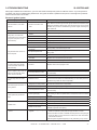
3.6 TROUBLESHOOTING
With proper installation and maintenance, your new Gas Heater should provide years of trouble-free service. If you do experience
a problem, refer to the Trouble Shooting Guide below. This guide will assist a qualified service person in the diagnosis of problems
and the corrective action to be taken.
Electronic Ignition System
Symptom
Possible Causes
Corrective Actions
1. No transmission, motor does
not turn.
a. Receiver must learn new
code.
Press and hold the receiver’s reset button until you hear 2 acoustic signals. After the second longer acoustic signal, release the reset button and
within the subsequent 20 seconds, press the down arrow on the remote
handset until you hear an additional long acoustic signal confirming the
new code is set.
2. No ignition. No tone.
a. Receiver
Replace receiver and reprogram code.
a. ON/OFF switch is in OFF
position.
Push switch to ON position.
b. Loose wire.
Secure wire.
c. Receiver.
Replace receiver and reprogram.
d. Bent pins on 8 wire connector.
Straighten pins on 8 wire connector.
3. No ignition; one 5 seconds
continuous tone (7 shorts beeps
might be heard prior to the 5
seconds tone).
4. No pilot flame and control continues to spark.
5. Pilot is lit and control continues
to spark. Valve shuts off after
10 to 30 seconds. Valve operates manually.
6. Pilot is lit, sparking stops if a
flame is present. Valve shuts off
after 10 to 60 seconds. Valve
does not work manually.
7. 3 short beeps while the motor
turns.
8. Pilot flame lights but there is no
main gas flow.
9. Pilot sparks, but pilot will not
light.
10. Glass soots.
11. Flame burns blue and lifts off
burner.
e. Valve.
Replace valve.
a. Air in the pilot supply line.
Purge the line or start ignition several times.
b. Thermocouple circuit wired
incorrectly.
Check polarity of the thermocouple wires.
c. No spark at pilot burner
Check spark gap, check wiring connection. Check for spark in location
along cable.
d. Valve.
Replace valve. Do not over tighten.
e. Over tightened thermocouple
interrupter.
Replace valve and thermocouple interrupter.
f. Receiver.
Replace receiver and reprogram code.
a. Receiver.
Replace receiver and reprogram code.
a. Thermocouple.
Replace thermocouple.
b. Low inlet pressure to valve.
Confirm sufficient inlet pressure to the valve. Adjust or replace inlet regulator if necessary.
c. Valve.
Replace valve and the thermocouple interrupter.
a. Batteries are low.
Replace batteries - quality alkaline recommended. WARNING: Creating
an electrical short between the batteries/battery box and metal parts of the
appliance may render the receiver inoperable.
a. Manual override know (if
equipped) is in MAN position.
Turn Manual override know to ON position.
b. Valve turned don to pilot flow.
Turn flame to high fire by pressing up button on remote handset.
c. Low inlet pressure to valve.
Confirm sufficient inlet pressure to the valve. Adjust or replace inlet regulator if necessary.
a. Correct gas supply.
Verify that incoming gas line ball valve is “open”. Verify that inlet pressure reading is within acceptable limits, inlet pressure must not exceed
50 mbar.
b. Ignitor gap is too large.
Verify that spark gap from ignitor to pilot hood is .43 cm.
c. Module is not grounded.
Verify module is securely grounded to metal chassis of heater.
a. Flame impingement on logs.
Adjust the log set so that the flame does not impinge on it.
b. Improper venturi setting.
Adjust the air shutter at the base of the burner.
c. Debris around venturi.
Inspect the opening at the base of the burner. It is imperative that NO
material be placed in this opening.
a. Insufficient oxygen being
supplied.
1. Check to make sure flue cap is installed properly and free of debris.
Make sure that flue system points are tight and have no leaks.
2. Check to make sure that no material has been placed in the opening at
the burner base or in the area of the air holes in the center of the base
pan beneath the burner.
3. Be sure glass is tightened properly on unit, particularly on top corners.
Heat & Glo • SL-550TRSI-AUE • 2079-902 Rev. K • 10/08
36
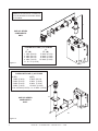
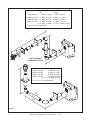
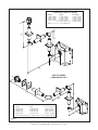
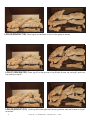
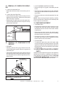
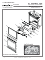
4.0 REPLACEMENT PARTS
SL-550TRSI-AUE
Service Parts
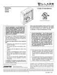
Service Parts Diagram
Beginning Manufacturing Date: June 2006
Ending Manufacturing Date: ______
9
10
11
12
20
13
19
14
18
17
15
Log Set Assembly
16
1
3
7
4
2
5
Part number list on following page.
37
Heat & Glo • SL-550TRSI-AUE • 2079-902 Rev. K • 10/08
6
8
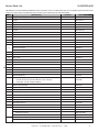
Service Parts List
SL-550TRSI-AUE
IMPORTANT: THIS IS DATED INFORMATION. When requesting service or replacement parts for your appliance please provide model
number and serial number. All parts listed in this manual may be ordered from an authorized dealer.
ITEM
COMMENTS
PART NUMBER
Log Set Assembly
LOGS-550TRSAUD
1
Log #1
SRV550-715
2
Log #2
SRV347-703
3
Log #3
SRV349-704
4
Log #4
SRV278-705
5
Log #5
SRV540-704
6
Log #6
SRV550-718
7
Log #7
SRV484-703
8
Log #8
SRV347-701
9
Grate
2021-007
10
11
Î
DESCRIPTION
Base Refractory
550-117
Burner Assembly N
2079-010
Burner Assembly P
2079-012
Burner Assembly B
2079-014
12
Glass Door Assembly
GLA-550TRS
13
Hood
SRV550-175
14
Top Louver
550-251A
15
Dress Guard
2079-040
16
Lower Door
2079-041
17
Switch Sensor
046-530
18
Junction Box
2078-027
19
Power Cord
546-251A
Blower Assembly 240V
100-505A
Exhaust Restrictor
347-299
20
Gasket Assembly
Includes: Burner Neck, Shutter Bracket, Vent, Seal Cap,
2115-080
Valve plate, and Air Passage Gaskets
Glass Latch Assembly
386-122A
Heat Shield (Control Module)
2078-121
Interior Top Heat Shield
2079-109
Mesh Assembly
561-330A
Mineral Wool
050-721
Multi Function Remote Control
REM-DLX-CE
Touch Up Paint
TUP-GBK-12
Wire Harness 20 in.
107-558A
Conversion Kits
Propane /Butane to Natural
PB2N-550I-AUE
Propane to Butane
P2B-550I-AUE
Natural to Propane
N2P-550I-AUE
Natural to Butane
N2B-550I-AUE
Pilot Orifice .0181
2098-518
Pilot Orifice .0121
2098-512
Additional service parts numbers appear on following page.
Heat & Glo • SL-550TRSI-AUE • 2079-902 Rev. K • 10/08
38
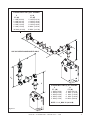
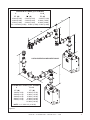
SL-550TRSI-AUE
Service Parts
Beginning Manufacturing Date: June 2006
Ending Manufacturing Date: ______
Valve Assembly Parts List
1
Valve Assembly
2
10
11
12
3
9
8
5
13
6
4
14
7
15
IMPORTANT: THIS IS DATED INFORMATION. When requesting service or replacement parts for your appliance please provide model
number and serial number. All parts listed in this manual may be ordered from an authorized dealer.
ITEM
DESCRIPTION
COMMENTS
PART NUMBER
Pilot Assembly N
2098-050
Pilot Assembly P
2098-051
2
Pilot Bracket
2079-104
3
Control Cable
2098-143
4
Module, Maxitrol
2098-142
5
Switch Assembly
2098-145
6
Block Control Wire
2098-148
7
240V Adaptor
2098-144
8
Flexible Gas Connector
383-302A
Orifice N (#40C)
582-840
1
9
Orifice P (.057C)
582-057
Orifice B (#55C)
582-855
10
Rheostat
491-510A
11
Valve Bracket
2089-120
12
Rheostat Knob
100-512
13
Thermocouple Block
2098-146
14
Gas Shutoff Assembly
2098-320A
Valve N
2098-130
Valve P
2098-131
15
39
Heat & Glo • SL-550TRSI-AUE • 2079-902 Rev. K • 10/08
LIMITED 10 YEAR WARRANTY
HEAT & GLO, a brand of Hearth & Home Technologies Inc.
In order to presumptively establish the dates to which your HEAT & GLO Limited 10 Year Warranty runs, you
must mail the completed warranty card to HEAT & GLO, a brand of Hearth & Home Technologies Inc., 20802
Kensington Boulevard, Lakeville, MN 55044, within 60 days of the date of heater installation. If you fail to do
so, you may be required to prove the date of installation before warranty work can be performed.
The warranty exclusions and limitations of liability are effective upon installation of the heater.
Subject to the conditions set forth herein, HEAT & GLO, a brand of Hearth & Home Technologies Inc. ("HEAT & GLO")
extends the following warranty with respect to HEAT & GLO, a brand of Hearth & Home Technologies Inc..
If HEAT & GLO is reasonably satisfied that any part or portion of the heater covered by this Limited Warranty is
defective in material or workmanship under normal use and service as described in the Operating Instructions,
HEAT & GLO will take the following actions:
1. If the defect is reported during the first year from the date of installation (stainless steel burners and fiber logs
are covered for 3 years), HEAT & GLO will replace or repair the defective components at its sole expense.
The decision whether to replace a component shall be made at HEAT & GLO's sole discretion. This Limited
Warranty does not cover components broken during shipping, misuse or careless handling. HEAT & GLO
shall be not responsible for any indirect, incidental, or consequential damages or for any costs other than
those incurred by HEAT & GLO to repair or replace the defective component. If components (including
venting) other than factory approved components are used, all warranty and liability on the heater is voided.
Defects reported after the first year will not be covered by warranty unless they fall within the purview
of paragraph 2 or 3 below.
2. If the following defects are reported during the second year after the date of installation, HEAT & GLO will
supply replacement parts at the current wholesale price: defective electrical or manual components, optional
components or accessories, and glass panels (not including glass panels broken during misuse or careless
handling). HEAT & GLO shall not be responsible for any labor, transportation or other costs. Furthermore,
it shall not be liable for any indirect, incidental or consequential damages.
3. HEAT & GLO will replace or repair a defective firebox or heat exchanger, at any time during the 10 years
from the date of installation. The decision whether to replace the defective component shall be made at HEAT
& GLO's sole discretion. HEAT & GLO shall not be responsible for any indirect, incidental or consequential
damages or for any costs other than those incurred by HEAT & GLO to repair or replace the defective
component.
This Limited Warranty is the exclusive remedy available to you. If HEAT & GLO cannot effectively resolve a
warranty problem in an expedient and cost-effective manner, it can discharge its entire warranty liability by
refunding the price of the product to you.
Products made by other manufacturers, whether sold with the heater or added thereafter, are NOT covered by
this Limited Warranty. The use of other unauthorized components will make this warranty null and void. This
Limited Warranty will also be void if the appliance is not installed by a qualified installer in accordance with
the Installation Instructions. Furthermore, the Limited Warranty will be void if the heater is not operated, at all
times, according to the Operating Instructions furnished with the heater. Any service work must be performed
by authorized service representatives.
EXCEPT TO THE EXTENT PROVIDED BY LAW, NO OTHER EXPRESS OR IMPLIED WARRANTIES,
INCLUDING WARRANTIES OF MERCHANTABILITY OR FITNESS FOR A PARTICULAR PURPOSE, SHALL
APPLY TO THE HEATER PRODUCT. In States that do not allow limitations on how long an implied warranty
lasts, or do not allow exclusion of indirect damages, those limitations or exclusions may not apply to you. You
may also have additional rights not covered in this Limited Warranty.
HEAT & GLO reserves the right to make changes at any time, without notice, in design, material, specifications
and prices. It also reserves the right to discontinue styles and products.
Heat & Glo • SL-550TRSI-AUE • 2079-902 Rev. K • 10/08
40
For Service or Replacement Parts Contact:
Melbourne
Jetmaster
444 Swan Street
Richmond 3121
(03) 9429-5573
Perth
Fireplace Corner
277 Lord Street
East Perth 6000
(08) 9228-2600
Sydney
Jetmaster
10 Martin Avenue
Arncliff 2205
(02) 9597-7222
41
Heat & Glo • SL-550TRSI-AUE • 2079-902 Rev. K • 10/08