1
Product Manual
PRQFESS|ONAL
12.5 Amp, Variable Speed,
Peak HP Router Combo
2-114
with Fixed Base, Plunge Base,
and D-Handle Base
Model No. 320. 28084
CAUTION!
follow
Read, understand
all Safety
instructions
and
Rules and Operating
in this Manual
before
using this product.
Sears,
Roebuck
www.craftsman.com
=
=
=
=
=
=
Warranty
Safety
Assembly
Description
Operation
Maintenance
= Troubleshooting
and Co.,
Hoffman
Estates,
IL 60179
Warranty
Page 2
Safety Symbols
Page 3
Safety Instructions
Pages 441
Unpacking
Pages 1142
Description
Pages 134 5
Assembly
Page 16
Operation
Pages 17-50
Maintenance
Pages 51-52
Troubleshooting
Pages 53
Accessories
Pages 54-55
Parts list
Pages 56-66
Sears Repair Parts Phone and Numbers
Back Cover
ONE YEAR FULL WARRANTY ON CRAFTSMAN PROFESSIONAL TOOL
If this Craftsman professional tool fails to give complete satisfaction within
one year from the date of purchase, return it to any Sears store or parts &
repair center or other craftsman outlet in the United States for free repair
(or replacement, if repair proves impossible).
This warranty does not include expendable parts such as lamps,
batteries, bits, or blades.
This warranty applies for only 90 days from the date of purchase if this
product is ever used for commercial or rental purposes
This warranty gives you specific legal rights, and you may also have other
rights which vary from state to state.
Sears, Roebuck and Co., Hoffman Estates IL 60179
,&
WARNING: Some dust created by using power tools contains chemicals
known to the state of California to cause cancer and birth defects or other reproductive harm.
SAVE THESE INSTRUCTIONS!
READ ALL INSTRUCTIONS!
28084 ManuaLRevised 07-0712
Page 2
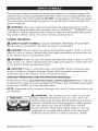
The purpose of safety symbols is to attract your attention to possible dangers. The
safety symbols, and the explanations with them, deserve your careful attention and
understanding. The symbol warnings DO NOT, by themselves, eliminate any danger.
The instructions and warnings they give are no substitutes for proper accident-prevention measures.
,_
WARNING:
Be sure to read and understand
all safety instructions
in this
manual, including all safety-alert symbols, such as "DANGER," "WARNING," and
"CAUTION," before using this router. Failure to follow all instructions listed below
may result in electric shock, fire, and/or serious personal injury.
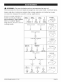
SYMBOL
_.
MEANINGS
SAFETY=ALERT
SYMBOL:
May be used in conjunction
_,
DANGER:
Indicates DANGER, WARNING,
with other symbols
or pictographs.
Failure to obey this safety warning WILL result in death or serious
injury to you or to others. Always follow the safety precautions
of fire, electric shock, and personal injury.
,_
WARNING:
CAUTION:
to reduce the risk
Failure to obey this safety warning CAN result in death or serious
injury to you or to others. Always follow the safety precautions
of fire, electric shock, and personal injury.
_.
OR CAUTION.
Failure to obey this safety warning
to reduce the risk
MAY result in personal
to you or others or property damage. Always follow the safety precautions
reduce the risk of fire, electric shock, and personal injury.
DAMAGE
PREVENTION
AND INFORMATION
injury
to
MESSAGES
These inform user of important information and/or instructions
that could lead
to equipment or other property damage if not followed. Each message is preceded
by the word "NOTE:" as in the example below:
NOTE: Equipment
not followed.
and/or
_,
W_ARYOUR
property
damage
WARNING:
may result if these
The operation
instructions
are
of any router can result in
foreign objects being thrown into your eyes, which can
result in severe eye damage. Before beginning power tool
operation, ALWAYS wear safety goggles or safety glasses
with side shield and a full-face shield when needed.
We recommend a Wide Vision Safety Mask for use over
eyeglasses or standard safety glasses with side shield,
available at Sears Stores or other Craftsman' Outlets.
28084 Manual Revised 07-0712
Page 3
WARNING:
BE SURE to read and understand
all instructions
before using this router. Failure to follow all instructions
fire and/or serious personal injury.
in this manual
may result electric
shock,
WORK AREA SAFETY
•
Keep your work area clean and well
areas invite accidents.
lit. Cluttered
•
Do not operate power tools in explosive environments,
such as in the
presence of flammable liquids, gases, or dust. Power tools create sparks,
which may ignite the dust or fumes.
-
Keep bystanders,
children, and visitors away while operating
Distractions can cause you to lose control.
-
Make your workshop
childproof
tools away when not in use.
•
Before using your router, make sure that the work area has ample lighting
and that there are no obstructions that will interfere with its safe operation.
with padlocks
workbenches
and dark
a power tool.
and master switches.
Lock
PERSONAL SAFETY
•
Know your power tool. Read this operator's manual carefully. Learn the
router's applications and limitations, as well as the specific, potential hazards
related to this tool.
-
Stay alert, watch what you are doing, and use common
operating a power tool.
•
Do not use this tool while tired or under the influence of drugs, alcohol, or
medication. A moment of inattention while operating power tools may result
in serious personal injury.
•
Dress properly. Do not wear loose clothing or jewelry. Pull back long hair.
Keep your hair, clothing, and gloves away from moving parts. Loose clothing
and long hair can be caught in moving parts. Air vents often cover moving
parts and should also be avoided.
•
Avoid accidental starting. Be sure switch is in the "OFF" position before
plugging in the tool. Do not carry tools with your finger on the switch.
Carrying tools with your finger on the switch or plugging in tools that have the
switch in the "ON" position invites accidents.
•
Remove adjusting keys or blade wrenches before turning the tool "ON."
A wrench that is left attached to a rotating part of the tool may result in
personal injury.
•
Do not overreach.
Keep proper footing and balance at all times. Proper footing and balance enables better control of the tool in unexpected situations.
28084 Manual Revised 07-0712
sense when
Page 4
Always secure your work. Use clamps or a vise to hold the workpiece
securely. It is safer than using your hand, and it frees both hands to operate
the tool.
•
Use safety equipment.
Always wear eye protection. A dust mask, nonskid safety shoes, hardhat, and/or hearing protection must be used for
appropriate conditions.
•
Do not use on a ladder or unstable support. Stable footing on a solid
surface enables better control of the tool in unexpected situations.
TOOL USE AND CARE
,_ WARNING: Be sure to read and understand all instructions before operating
this router. Failure to follow all instructions listed below may result in electric
shock, fire, and/or serious personal injury.
o
Always use clamps or other practical ways to support and secure the
workpiece to a stable platform. Holding the workpiece by hand or against
your body is unstable and may lead to loss of control.
Do not force the tool. Use the correct tool and bit for your application. The
correct tool and bit will do the job better and more safely at the rate for which
it is designed.
Do not use the tool
cannot be controlled
if switch does not turn it "ON" or "Off." Any tool that
with the switch is dangerous and must be repaired.
•
Disconnect
the ptug from the power source before making any
adjustments,
changing accessories, or storing the tool. Such preventive
safety measures reduce the risk of accidentally starting the tool.
•
Never leave the tool running.
comes to a complete stop.
•
Store idle tools out of the reach of children
Tools are dangerous in the hands of untrained
o
Maintain tools with care. Keep cutting tools sharp and clean. Properly
maintained tools with sharp cutting edges are less likely to bind and are
easier to control.
Always turn it off. Do not leave the tool until it
and other untrained
users.
persons.
Check for misalignment
or binding of moving parts, breakage of parts,
and any other condition that may affect the tool's operation. If damaged,
have the tool serviced before using. Many accidents are caused by poorly
maintained tools.
•
Use only accessories
that are recommended
that may be suitable for one tool may become
another tool.
28084 Manual Revised 07-0712
for this tool. Accessories
hazardous when used on
Page 5
ELECTRICAL
SAFETY
_, WARNING: Do not permit fingers to touch the terminals
installing or removing the plug from the outlet.
of the plug when
o
Double insulated tools are equipped with a polarized plug (one blade is
wider than the other). This plug will fit in a polarized outlet only one way. If
the plug does not fit fully in the outlet, reverse the plug. If it still does not fit,
contact a qualified electrician to install a polarized outlet. Do not change the
plug in any way.
•
Double insulation [] eliminates the need for the three-wire, grounded, power
cord and grounded power-supply
system. Applicable only to Class II (doubleinsulated) tools.
•
This router motor is double insulated.
,_
WARNING:
precautions
•
Double insulation
when operating
does not take the place of normal safety
this tool.
Before plugging in the tool, be sure that the outlet voltage supplied is within
the voltage marked on the tool's data plate. Do not use "AC only" rated tools
with a DC power supply.
Avoid body contact with grounded
surfaces,
ranges, and refrigerators. There is an increased
body is grounded.
such as pipes, radiators,
risk of electric shock if your
Do not expose power tools to rain or wet conditions
or use power tools
in wet or damp locations. Water entering a power tool will increase the risk of
electric shock.
•
inspect tool cords for damage. Have damaged tool cords repaired at a
Craftsman Service Center. Be sure to stay constantly aware of the cord's
location and keep it well away from the moving router.
•
Do not abuse the cord. Never use the cord to carry the tool or to pull
the plug from an outlet. Keep the cord away from heat, oil, sharp edges,
and moving parts. Replace damaged cords immediately. Damaged cords
increase the risk of electric shock.
EXTENSION
CORDS
Use a proper extension cord. Use only cords listed by Underwriters
Laboratories (UL). Other extension cords can cause a drop in line voltage,
resulting in a loss of power and overheating of the tool.
For this tool, an AWG (American Wire Gauge) size of at least 14-gauge is
recommended
for an extension cord of 25-ft. or less in length. Use 12-gauge
for an extension cord of 50-ft. Extension cords 100-ft. or longer are not
recommended.
28084 Manual Revised 07-0712
Page 6
h
A smaller wire gauge size has greater capacity than a larger number (14-gauge
wire has more capacity than 16-gauge wire; 12-gauge wire has more capacity than 14-gauge). When in doubt, use the smaller number. When operating
a power tool outdoors, use an outdoor extension cord marked "W-A" or "W".
These cords are rated for outdoor use and reduce the risk of electric shock.
,_
CAUTION:
Keep the extension
cord clear of the working
area. Position the
while
n
cord so that it will not get caught on lumber, tools, or other obstructions
you are working with a power tool.
,_ WARNING: Check extension cords before each use. If damaged, replace
immediately. Never use a tool with a damaged cord, since touching the damaged
area could cause electrical shock, resulting in serious injury.
SAFETY SYMBOLS
FOR YOUR TOOL
The label on your tool may include the following symbols.
V ......................................................
Volts
A.......................................................
Amps
Hz .....................................................
Hertz
W. .....................................................
Watts
min ...................................................
Minutes
"%'
...............................................
Alternating
---=
..............................................
no
[]
................................................
..................................................
.../min ...............................................
..............................................
current
Direct current
No-load speed
Class II construction,
Revolutions
Double Insulated
or Strokes per minute
Indicates danger, warning or caution.
It means
attention? Your safety is involved.
SERVICE SAFETY
•
If any part of this router is missing or should break, bend, or fail in any way;
or should any electrical component fail to perform properly: shut off the
power switch, remove the router plug from the power source, and have the
missing, damaged or failed parts replaced before resuming operation.
•
Tool service must be performed only at a Craftsman Parts and Repair
Center. Service or maintenance performed by unqualified personnel could
result in a risk of injury.
•
Use only identical replacement
parts when servicing a tool. Follow the
instructions in the maintenance section of this manual. Use of unauthorized
parts or failure to follow maintenance
shock or injury.
28084 Manual Revised 07-0712
instructions
may create a risk of electric
Page 7
SAFETY RULES FOR ROUTERS
_,
CAUTION:
Cutting
bits coast after the router is switched
•
Hold the tool by insulated gripping surfaces (handles) when performing
an operation where the cutting tool may contact hidden wiring or its own
cord. Contact with a "live" wire will make the exposed metal parts of the tool
"live" and shock the operator.
o
Maintain a firm grip on the router with both hands to resist torque upon
starting the router.
•
Never attempt to use the router motor without first installing it in an approved
base. Failure to heed this warning could result in personal injury and damage
to the motor.
•
Make sure that the router motor does not move up or down when clamped
in a fixed base.
•
Do not hold the router by hand for use in an upside-down
or horizontal
position. The router motor can separate from the base if it is not properly
attached according to the instructions.
•
Tighten the collet/nut
securely to prevent the cutting bit from slipping. If
the collet/nut is not securely tightened, the cutting bit may detach during use,
causing serious personal injury.
•
Never tighten the collet/nut
without a cutting
bit installed
off.
in the collet/nut.
Use clamps or other practical ways to secure and support the workpiece
to a stable platform, and hold the workpiece rigidly in position. Holding the
workpiece by hand or against your body is unstable and may lead to loss of
control.
Never hold the piece being cut in your hands or across your legs. It is
important to support and clamp the workpiece properly in order to minimize
body exposure, bit binding, and loss of control.
•
Always
keep the chip shield clean and in place.
•
Stay alert and clear the router cutting-bit
path of any obstructions
before
starting the motor. Keep the cutting area clear of all foreign objects while the
router motor is running.
•
Check
•
Make sure that the cutting bit is not in contact with the workpiece before
the switch is turned on. The bit must always be running at full speed before
contacting the workpiece.
to see that the cord will not "hang up" during routing operations.
Keep hands clear of the cutting
prevent personal injury.
•
Provide clearance
through-cutting.
28084 Manual Revised 07-0712
bit when the router motor is running to
under the workpiece
for the router cutting
bit when
Page 8
o
Keep cutting
pressure
constant.
Do not overload the motor.
o
Use only sharp cutting bits that are not chipped or cracked.
bits will cause stalling and can burn the workpiece.
o
Never use this router motor with a cutting bit larger than 34/2-inches
•
Always use cutting bits that are designed for this router. Never use
cutting bits that are larger in diameter than the opening in the router subbase. Cutting bits that have cutter diameters larger than the opening could
cause possible loss of control or create other hazardous condition that could
cause serious personal injury.
Blunt cutting
in diameter.
The sub-base
on this router has an opening of 1=1/4 inch. To use cutting
bits with a larger diameter, install and use a sub-base with a larger diameter
opening (sold separately at Sears stores or other Craftsman outlets).
•
Do not use large router cutting bits for freehand routing. Use of large
cutting bits when freehand routing could cause loss of control or create
hazardous conditions that could result in serious personal injury. If using a
router table, large bits should be used for edging only.
•
Be sure the cutting bit is centered
prior to template-guide
applications
finished work.
•
Do not remove more than 1/8 inch in a single pass. Excessive depth of
cut can result in loss of control that could result in personal injury.
in the template guide (sold separately)
to avoid personal injury or damage to
Turn the router motor OFF after completing a cut, and let it come to a
complete stop before removing the router from workpiece.
•
Let the router motor come to a complete
stop before putting the router
down. Cutting bits coast after the power is turned off.
•
Only use router tables that conform to safe woodworking
practices and offer
proper guarding for the cutting bit. Use router tables that are UL classified
and identified as suitable for use with this specific router model. Failure to
comply could result in serious personal injury.
•
Only use router tables with on-board,
switch-controlled
receptacles.
Failure to use router tables with all the appropriate safety features could
result in serious personal injury.
•
Disconnect
or changing
•
Be carefut not to touch the coUet/nut or cutting bit with your hands or
fingers if you are changing a bit immediately after use. The heat buildup from
cutting could cause severe burns. Always use the wrench provided.
-
Avoid "climb cutting." See the OPERATION section in this manual. "Climb
cutting" increases the chance for loss of control resulting in possible serious injury.
28084
Manual
Revised
the tool from the power source before making
cutting bits.
07-0712
any adjustments
Page 9
,&
WARNING: Use of this product can generate dust containing chemicals
known to the state of California to cause cancer, birth defects or other
reproductive
harm. Some examples
•
Lead from lead-based
•
Crystalline
•
Arsenic and chromium
of these chemicals
are:
paints.
silica from bricks and cement and other masonry
from chemically
treated
products.
lumber.
Your risk from these exposures varies, depending upon how often you do this
type of work. To reduce your exposure to these chemicals:
o
Work in a well-ventilated
area.
•
Work with approved safety equipment, such as those dust masks that are
specially designed to filter out microscopic
particles.
Avoid prolonged contact with dust from power sanding, sawing, grinding, drilling,
and other construction activities. Wear protective clothing and wash exposed
areas with soap and water. Allowing dust to get into your mouth, eyes or lie on
the skin may promote absorption of harmful chemicals.
WARNING:
Use of this tool can generate and/or
disburse
dust, which may
cause serious and permanent respiratory or other injury. Always use NIOSH/
OSHA approved respiratory protection appropriate for the dust exposure. Direct
the particles away from face and body.
ADDITIONAL
,_
RULES
WARNING:
FOR SAFE OPERATION
Be sure to read and understand
all instructions listed below may result in electric
personal injury.
all instructions.
Failure to follow
shock, fire and/or
serious
Know your power tool Read this operator's manual carefully. Learn the
applications and limitations, as well as the specific potential hazards related
to this tool. Following this rule will reduce the risk of electric shock, fire, or
serious injury.
•
Always wear safety glasses or eye shields when using this router. Everyday
eyeglasses may have impact-resistant
lenses, but they are not safety
glasses.
•
Protect
•
Protect your hearing. Wear appropriate personal hearing protection
during power-tool use. Under some conditions noise from this product
contribute to hearing loss.
•
your lungs.
Wear a facemask
or dust mask if the operation
All visitors and bystanders
must wear the same safety equipment
operator of the router should wear.
28084 Manual Revised 07-0712
is dusty.
may
that the
Page 10
•
Inspect tool cords periodically and, if they are damaged, have them repaired
at your nearest Craftsman Service Center. Be aware of the cord location.
•
Always check the tool for damaged parts. Before further use of the
tool, a guard or other part that is damaged should be carefully checked to
determine if it will operate properly and perform its intended function. Check
for misalignment or binding of moving parts, breakage of parts, and any other
condition that may affect the tool's operation. A guard or other part that is
damaged should be properly repaired or replaced at a Sears Service Center.
-
Inspect
,,
Save these instructions. Refer to them frequently and use them to instruct
others who may use this tool. If someone borrows this tool, make sure they
have these instructions, also.
and remove
all nails from lumber before routing.
A
_1_ WARNING: Your router should never be connected to the power source
when you are assembling parts, making adjustments, installing or removing
collets/nuts or cutting bits, cleaning, or when it is not in use. Disconnecting the
router will prevent accidental starting, which could cause serious personal injury.
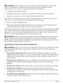
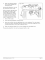
1.
The router motor is attached to the fixed base, and the 1&-in. collet nut is
already installed when you open the package. Carefully lift the router motor
in the fixed base out of the storage/carrying
case and place it on a stable,
flat surface.
2.
Lift the plunge base and the D-handle
on a flat surface.
3.
Open the parts bag to locate the following:
base out of the case and place them
Edge Guide
• 1/4-in. Collet/Nut
• Collet/Nut
wrench
• Power Cord
- 2 Sawdust-Extraction
Hoods
• 2 Screws to attach the Sawdust-Extraction
Hood to the Plunge Base
• Chip Shield for Plunge Base
• Depth-Adjustment
4.
Wrench
Inspect the items carefully to make sure that no breakage or damage has
occurred during shipping. If any of the items mentioned is missing, (refer to
"PARTS LIST" illustration), return the router to your nearest Sears store or
Craftsman outlet to have the router replaced.
28084 Manual Revised 07-0712
Page 11
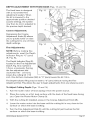
_h, WARNING:
If any parts are broken or missing, do not attempt
to plug in
the power cord or operate router until the broken or missing parts are replaced.
Failure to do so could result in possibly serious injury.
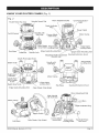
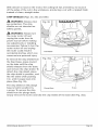
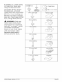
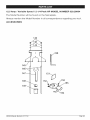
PARTS LIST (Fig. 1)
Fig. 1
1. Fixed Base and Router motor with 1/2-in. Collet/Nut
4. Edge Guide
5. 1/4-in. collet/Nut
6. Collet/Nut
Wrench
2. Plunge Basse
7. 2 Sawdust Extraction_
8. Depth-AdjustmentWrench
9. Chip Shield for Plunge
3. D-Handle Base
Base
10.2 Screws
28084
Manual
Revised
07-0712
Page 12
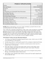
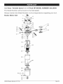
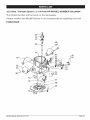
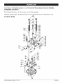
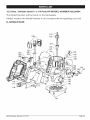
KNOW YOUR ROUTER
COMBO
(Fig. 2)
Fig. 2
Variable Speed Dial
Router Motor Top Cap
Micro Adjustment Dial
/
"Live Tool Indicator"
Light
Depth Indicatol
Ring
On/Off
\
Handles with
Soft-Grip
Coarse
Power Outlet
Motor Clamp
Adjust-
Edge Guide
Locking Knob
Sub Base
Edge Guide Mounting Slot
Collet/Nut
Spindle Lock
Integrated Depth-adjustment
Wrench hole
Edge Guide Mounting Slot
Sawdust Extraction Hood
Depth-Rod Adjust Knob
Depth _
Depth Rod /
/_
igD__ePthr
Indicator
/I
Depth-Rod _
Micro Adjust
Screw
Depth-Stop
Turret
Sub-Base
Edge Guide Mounting Slot
Sawdust Extraction
Hood
Clear Plastic Chip Shield
Micro Adjustment Dial
Depth Indicator Ring
Motor_Clam
Sub-Base
28084
Manual
Revised
Clear Plastic Chip Shield
07-0712
Coarse Adjustment Knob
Edge Guide
Locking Knob
Sawdust Extraction Hood
Page 13
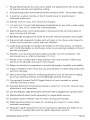
PRODUCT
SPECiFiCATiONS
Rating
12.5 Amps
No load Speed
12000-25000RPM
Peak H P
2-1/4
Input
120V, 60Hz AC
Collets/Nuts
and Cutting
Bit Shank Diameters
1/4 in., 1/2 in.
Fixed Base Diameter
6 inches
Plunge Base Diameter
6 -11/16 inches
D-Handle
Base Diameter
6 inches
Sub-Base
Opening (Diameter for cutting
Sub-Base
Thickness
bit use)
1-1/4 inches
0.23 inches (6mm)
Fixed Base Depth of Cut
1-3/4 inches (45mm)
Plunge Base Depth of Cut
2-1/8 inches (55mm)
D-handle
1-3/4-inches
Base Depth of Cut
NOTE: Before attempting to use your router, familiarize
operating features and safety requirements.
(45mm)
yourself with all of the
Your router has a precision-built
electric router motor, and it should be connected
only to a 120-volt, 60-Hz AC ONLY power supply (normal household current).
Do not operate on direct current (DC). This large voltage drop will cause a loss
of power and the router motor will overheat. If the router does not operate when
plugged into a correct 120-volt, 60-Hz AC ONLY outlet, check the power supply.
This router has a 10-ft, 2-wire power cord (no adapter needed).
This Router
Combo
has the following
features:
1.
12.5 Amp, 244 Peak HP, Variable Speed Router motor, which runs at 12,000
to 25,000 RPM (no-load speed).
2.
Variable Speed Dial for matching the speed to the workpiece material and bit size.
3.
Electronic-Feedback
Circuitry
quality finish in all materials.
4.
Soft-start feature minimizes the torque twist common with larger router
motors by limiting the speed at which the router motor starts. This also
increases the motor's life.
5.
Quick-Clamp
System allows the router motor to be changed
Plunge, and D-Handle bases without tools.
6.
Fixed Base and D-Handle
for accurate set-ups.
28084 ManuaLRevised 07-0712
maintains
constant
speed under load for a
among Fixed,
bases feature coarse and fine depth adjustments
Page 14
7.
Plunge Base features fine and micro depth-rod
for precise set-ups and repetitive cutting.
8.
Smooth plunge action lowers the bit into the workpiece at 90 ° for accurate cutting.
9.
3-position
individual
10. Spindle
auxiliary handle on the D-handle
preference.
Lock for easy, one-wrench
adjustments
base for positioning
to
bit changes.
11.1/4-inch
and 1/2-inch Self-Releasing Collets/Nuts
of 1/4-in. and 1/2-in. router bits, sold separately.
12. Detachable power cord: replaceable
easy carrying and storage.
13. Ball Bearings throughout
with turret stops
for use with a wide variety
to prolong tool life and removable
for
the motor for smooth, efficient operation and long life.
14. Ergonomically designed handles with soft grip on the three router bases for
comfort and maximum control with less vibration.
15. Large base openings and large chip shields on the three bases, combined
with 3 LED Worklights on the Router motor to provide high visibility of the bit
and the workpiece.
16. Durable, non-marring sub-bases glide smoothly over the workpiece.
sub-bases have a cutter-bit opening of 1-1/4 in.
The
17. Router motor constructed of high-density nylon and precision-milled
aluminum for strength and exact fit into bases.
cast
18. Bases constructed
of magnesium to provide lightweight,
19. Impact-resistant
router-motor
tool from damage.
durability, and stability.
top cap and handles on bases help protect the
20. Heavy-duty Edge Guide for routing applications such as decorative
grooving, dadoing, slotting, and straightedge planing/trimming.
edging,
21. Conveniently located On/Off Toggle Switch is front mounted for added
visibility and easy access.
22. Sawdust-Extraction
attachment,
Hood allows bases to attach to 1-1/4-inch vacuum hose
sold separately.
23. Live Tool Indicator Ught shines green when the router is plugged into a power source.
24. Replaceable
25. Includes
Brushes (sold separately)
impact-resistant
for dependable
case for easy carrying
26. Table Mounting Holes on bases for mounting
(available separately).
service.
and storage.
the router to a router table
27. Integrated depth-adjustment-wrench
opening for adjusting the depth of cut
from above a routing table with the depth-adjustment
wrench.
28084 ManuaLRevised 07-0712
Page 15
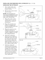
NOTE: This tool is shipped completely assembled. To change the router motor
from one base to another, install or remove cutting bits, add accessories such as
sawdust ejection hoods for hook-up to vacuums, or install the heavy-duty edge
guide, see the following instructions.
28084
Manual
Revised
07-0712
Page 16
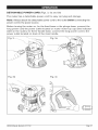
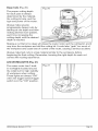
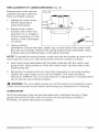
DETACHABLE
POWER CORD (Figs. 3, 3a and 3b)
The router has a detachable
power cord for easy carrying
and storage.
Note: Always attach the detachable power cord to the router before connecting the
power cord to the power source.
Before turning the router on, for the fixed base or the plunge base, connect the
long power cord the power outlet located on router motor top cap (See indicator
label on the router); for the D-handle base, connect the long power cord to the
power outlet located on back of the main handle.
Fig. 3_
\_
Fig. 3a
"t
\
Fig. 3b
28084 ManuaLRevised 07-0712
Fig. 3c
Page 17
TOGGLE
"ON/OFF"
SWITCH
(Fig. 4)
Your router motor is turned
"ON" and "OFF" by the toggle
switch located on the top cap
of the router motor.
The left side of the toggleswitch (as you face it) is
marked "1" for "ON" and the
right side (as you face it) is
marked "0" for "OFF."
To turn the router motor "ON,"
Push the toggle switch to the
left side marked "1," or "ON."
To turn the router motor
"OFF," Push the toggle switch to the right side marked
"0," or "OFF."
1.
Always hold the router and cutting
the toggle switch "ON."
bit away from the workpiece
when turning
2.
Contact the workpiece with the router and cutting
has fully reached the selected speed.
3.
Remove the router and cutting bit from the workpiece only after turning the
router motor "OFF," and after the cutting bit has come to a complete stop.
bit only after the router
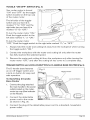
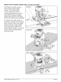
TRIGGER SWITCH and LOCK=ON BUTTON for D=HANDLE BASE ROUTER (Fig. 5)
The D-handle
base features
Fig. 5
an on-off trigger switch and
a lock-on button for easy and
safe operation.
To Start/Stop
Base Router
D=handie
Connect the plug attached
the main handle to the power
outlet located on the routermotor top cap (See indicator
on the Router).
2_
Connect
the detachable
power cord to the router
as shown in Fig. 3b.
3_
Connect the plug of the detachable
power outlet.
28084 Manual Revised 07-0712
power cord to a standard,
household-
Page 18
4.
Start the router by turning on the router motor (see Fig. 14), then squeezing
the ON/OFF trigger switch (see Fig. 5).
5.
To stop the router, release the ON/OFF trigger
switch to the right side marked "0" ("OFF").
6.
To lock the ON/OFF trigger switch in the "ON" position, press trigger switch
and, while holding it "ON," press in the lock-on button located on the left
side of the handle (see Fig. 5).
7.
The lock-on button allows the operator to keep the router running without
squeezing the trigger switch. This is useful for continuous routing applications.
8.
To release the power lock-on
This will turn the router off.
LiVE=TOOL
iNDiCATOR
button,
switch or push the toggle
press and release the trigger
switch.
LIGHT (Figs. 6 and 6a}
Your router has a Live-Tool
Indicator light located on the
router-motor top cap adjacent
to where the power cord
enters the router motor. This
Fig. 6
green light is always on when
router motor is plugged into a
power source.
The D-Handle
base has an
Live Tool Indicator
additional light Ioacting on the
back of the main handle.
Fig. 6a
28084 ManuaLF_vised
07-0752
Live Tool Indicator
Page 19
SELECTING THE CUTTING BiT
This router comes with 1/4-in. and 1/2-in. collets/nuts that accept 1A-inchdiameter and 1/2-inch-diameter
shanked cutting bits, respectively.
,_
WARNING:
Do not use router cutting
bits that have a cutting-bit
diameter
larger than 1-I/4 inches when using the router with the sub-bases included with
this combo, as they will not fit through the sub-base opening and will cause
damage to the sub-base and the motor and could cause serious personal injury
to the operator.
NOTE: The sub-base installed on this router has an opening of 14/4-inches. To
use cutting bits with a larger diameter, use a sub-base with a larger opening,
sold separately at Sears stores or other Craftsman outlets.
WARNING:
When using router cutting
bits with a cutter diameter
larger
than 1-1/2 inches, always have the speed dial set at number 1 or 2. Refer to the
Variable Speed Selection Chart located on top cap of the router motor for the
maximum speeds to use with various cutting-bit diameters. Failure to follow
these instructions could cause loss of control of the router in the workpiece,
causing possibly serious personal injury.
28084
ManuaLRevised
07-0712
Page 20
iNSTALLiNG
AND REMOVING
THE CUTTING
BiT (Figs. 7, 8, 8a)
iNSTALLiNG THE CUTTING BiT
1.
Turn router
motor off
Fig. 7
and unplug it from the
power source.
Collet
Nut
2.
Remove the router motor
from its base.
\
Spindle Lock
NOTE: See instructions for
removing and installing the router
motor in the fixed base, plunge
base, and D-handle base.
3.
Place the router motor
upside down on its top
cap with the collet/nut
pointing up.
Fig. 8
4.
Press the spindle-lock
button to engage and
lock the spindle shaft and
collet/nut (Fig. 7).
/
Cutters
Bit Shank
5.
Place the wrench on the
collet/nut, and turn it
counter-clockwise
to loosen
Spindle Lock
collet/nut slightly to accept
the cutting-bit shank.
6.
Insert the cutting bit
shank into the collet/nut
assembly as far as it will
go, then back the shank
out until the cutters are
Fig. 8a
approximately
1/8 to 1/4inch away from the face of
the collet/nut (Fig. 8, 8a).
7.
With the cutting bit
inserted and the spindle
lock button pressed in to
engage the shaft, place
the wrench on the collet/
nut and turn it clockwise
Cutters
_
Collet/Nut
until the router-cutting
bit and the collet/nut are
firmly tightened.
28084 Manual Revised 07-0712
Page 21
_.
WARNING:
Tighten the collet/nut
securely to prevent the cutting
slipping. If the collet/nut is not securely tightened,
during use, causing serious personal injury
the cutting
bit from
bit may detach
NOTE: To ensure proper gripping of cutting-bit
shank and minimize run-out,
shank of the cutting bit must be inserted into the collet/nut at least 5/8-inch.
CAUTION:
cutting
To prevent damage
to tool, do not tighten the collet/nut
without
THE CUTTING
BIT (Figs. 7, 8, 8a)
1.
Turn the router motor off and unplug the router from the power source.
2.
Remove the router motor from the base.
3.
Place the router motor upside down on its top cap, with the collet/nut
pointing up.
4.
Press the spindle-lock
collet/nut (Fig. 7).
Place the wrench
collet/nut
6.
a
bit installed.
REMOVING
5.
the
button to engage and lock the spindle shaft and the
on the collet/nut
and turn it counterclockwise
to loosen
slightly.
Remove the cutting-bit
shank (Fig. 8).
NOTE: The collet/nut is self-releasing;
it is not necessary to strike the collet/nut
to free the router cutting bit. If the cutting bit seems stuck after use, loosen the
collet/nut a little more until it releases.
COLLET/NUT
CARE
1.
From time to time, inspect the collet/nut
it is gripping the cutting bit properly.
2.
With the router cutting bit removed and the spindle lock engaged, turn the
collet/nut counterclockwise
until it is free from the motor's spindle shaft.
3.
Blow the collet out with compressed
air, and clean the tapered
collet/nut with a tissue or a fine brush.
4.
Always make sure that the cutting-bit shank, collet/nut, and router-motor
spindle are clean and free of woodchips, dust, residue, grease, and rust
before installing.
5.
Apply a small amount of machine oil to the spindle
6.
Replace worn or damaged
28084 Manual Revised 07-0712
collets/nuts
to make sure that it is clean and that
inside of the
shaft if it looks dry.
immediately.
Page 22
CUTTING
BITS
Get faster, more accurate
cutting
results by keeping cutting
1.
Remove all accumulated
2.
When sharpening cutting bits, sharpen
Never grind the outside diameter.
3.
Be sure, when sharpening the end of a cutting bit, to grind so that the
clearance angle remains the same as it was originally.
iNSTALLiNG
,_
pitch and gum from cutting
bits clean and sharp.
AND REMOVING
WARNING:
bits after each use.
only the inside of the cutting
THE ROUTER
edge.
MOTOR
Never use the router motor without
installing
it into either the
fixed, plunge, or D-handle bases in this Router Combo. Failure to do so could
result in serious personal injury and damage to the motor.
NOTE: Install the collet/nut and router cutting bit you are going to use before
installing the router motor in the fixed base, plunge base or D-handle base. See
"Installing and Removing the Cutting Bit" section.
WARNING:
Always turn the router motor off and unplug the router from the
power source before making any adjustments or installing accessories.
Failure to
turn the router motor off and unplug the router could result in accidental starting,
which can cause serious personal injury.
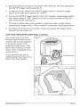
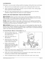
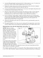
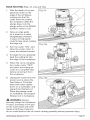
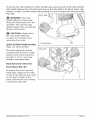
To Install Router
1.
2_
3.
Motor in Fixed Base (Fig. 9)
Turn the router motor off
and unplug the router from
the power source.
Fig. 9
Place the fixed base on
flat surface.
With the back of the fixed
base facing you, open the
router motor clamp (A).
4_
Press in the Coarse
Adjustment Knob (B) while
aligning the router motor's
slot with the pin in the
fixed base.
5_
When the motor's slot is aligned and engaged
router motor down into the fixed base.
6.
When the coarse-adjustment
knob is pressed in, the router motor can be
moved up or down to set coarse adjustments.
7.
After all adjustments
28084 Manual Revised 07-0712
are made, securely
into the base's pin, slide the
close the router-motor
clamp.
Page 23
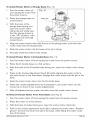
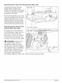
To Install Router Motor
in Plunge Base (Fig. 10)
1.
Turn the router motor off
and unplug the router from
the power source.
2_
Place the plunge base on
a flat surface.
3.
With the back of the
Fig. 10
MotorSlot
plunge base facing you,
open the router-motor
clamp (A) and make sure
that the plunge action is
in the "UP" position, with
the plunge lock lever (B)
locked down.
\A
4.
Align the router motor's slot with the pin in the plunge base, and lower the
router motor into the plunge base.
5.
Slide the router motor into the base as far as it will go.
6.
Securely
close the router-motor
To install Router Motor
clamp.
in D-Handle
Base (Fig. 11)
Turn the router motor off and unplug the router from the power source.
2.
Place the D-handle
base on a flat surface.
3.
With the back of the D-handle
base facing you, open the router-motor
clamp
(A).
4_
5_
6.
Press in the Coarse Adjustment Knob (B) while aligning the router motor's
slot with the pin in the fixed base. Engage the motor's slot with the pin in the
base.
Slide the router motor down into the D-handle
base.
When the coarse-adjustment
knob is pressed
moved up or down to set coarse adjustments.
in, the router motor can be
After all adjustments
To Remove
Router
are made, securely close the router-motor
Motor
clamp.
From Fixed Base (see Fig. 9)
1.
Turn the router motor off and unplug the router from the power source.
2.
Place the router on a flat surface.
3.
With the back of router facing you, open the router-motor
4.
Push in the coarse adjustment knob (B) to release the router motor "Position
groove" (C) from the lock hook (D) in the base, while lifting the router motor
free of the base.
28084 Manual Revised 07-0712
clamp (A).
Page 24
5.
Set the router motor upside down on its top cap with the collet/nut
up, and remove the cutting bit.
6.
Store the router motor and base in the carry/storage
To Remove
Router
Motor From Plunge
pointing
case when not in use.
Base (see Fig. 10)
1.
Turn the router motor off and unplug the router from the power source.
2.
Place the router on a flat surface.
3.
With the back of the plunge base facing you, open the router-motor clamp (A)
and make sure that the plunge action is in the "UP" position with the plunge
lock lever (B) locked down.
4.
Lift the router motor straight up and out of the base, sliding the pin in the
router motor free from the slot in the plunge base.
5.
Set the router motor upside down on its top cap with the collet/nut
up, and remove the bit.
6.
Store the router motor and base in the carry/storage
To Remove
Router
Motor From D=handle
1.
Turn the router motor off
and unplug the router from
the power source.
2.
Place the router (Dhandle base/router
motor)
3.
pointing
case when not in use.
Base (see Fig. 11)
Fig. 11
on flat surface.
J
C
D
With the back of router
facing you, open the
router motor clamp (A).
4.
Push in the coarse
adjustment knob (B) to
release the router motor
"Position groove" (C) from
the lock hook (D) in the base, while lifting router motor free of base.
5.
Set the router motor upside down on its top cap with the collet pointing
and remove the cutting bit.
6.
Store the router motor and base in the carry/storage
28084 Manual Revised 07-0712
up
case when not in use.
Page 25
,_
WARNING:
Always remove cutting
bits from the collet/nut
when the router is
not being used. Leaving bits installed could result in an accident
personal injury.
causing serious
Three Mounting
Base (Fig. 12)
Positions
For Auxiliary
Handle Of D-Handle
There are three mounting
positions on D-handle base
for auxiliary handle (Fig. 12);
you can choose the desired
position to install the auxiliary
handle for ease of operation.
1.
Turn the auxiliary handle
counterclockwise
to loosen
it and remove the auxiliary
handle from the base.
2_
Align the screw on the
auxiliary handle with the
desired mounting hole
located on the left side of
the D-handle base.
3.
Turn the auxiliary
ADJUSTING
WARNING:
handle clockwise
until it is firmly tightened.
DEPTH OF CUT
Your router should never be turned
on or connected
to the
power source when you are assembling parts, making adjustments, installing
or removing collets/nuts or cutting bits, cleaning, or when it is not in use.
Disconnecting the router will prevent accidental starting, which could cause
serious personal injury.
NOTE: All depth adjustments on the Fixed Base or D-Handle
made with the router motor clamp open.
Base must be
NOTE: For the Fixed Base or D-Handle Base, the cutting bit depth equals the
amount of the cutter that is exposed below the surface of the sub-base.
28084 Manual Revised 07-0712
Page 26
DEPTH ADJUSTMENT
WiTH FIXED BASE (Figs. 13 and 14)
The fixed base is designed
with a micrometer-fine
Fig. 13
adjustment system. When
the bit is lowered to the
F_
approximate position desired
(coarse setting), the system
may then be micro adjusted to
the precise depth desired.
Coarse
E
Adjustment:
Depressing the Coarse
Adjustment Knob (B) allows
you to quickly lower or raise
the cutting bit to one of three
depth settings.
Fig. 14
Fine Adjustments:
NOTE: Before making fine
adjustments,
reset the Depth
Indicator Ring to "0" (zero)
(E, Fig. 9).
E
B._
The Depth Indicator Ring (E),
located on the Fine Adjustment
Dial (F, Fig. 9) is marked in
1/64-in. increments. Turning
the fine adjustment dial
clockwise 180 ° (1/2 turn),
lowers the cutting bit 1/16
inch. One full turn clockwise (360) to "0" (zero) lowers the bit 1/8 in.
The Depth Indicator Ring may be reset to "0" (zero) without moving the Fine
Adjustment Dial. This allows the user to begin adjustments from any reference point.
To Adjust
Cutting
Depth
(Figs. 13 and 14)
1.
Turn the router motor off and unplug it from the power source.
2.
Place the router on a flat, level surface with the back of the fixed base facing
you. Open the Router Motor Clamp (A).
3.
With the cutting
4.
Lower the router motor into the base until the cutting
surface on which the base is sitting.
5.
Turn the Fine Adjustment Dial (F) until the cutting
surface on which the base is sitting.
bit installed,
28084 Manual Revised 07-0712
press in the Coarse Adjustment
Knob (B).
bit is very close to the
bit just touches
the flat
Page 27
6.
Lock the Router Motor Clamp (A).
7.
While continuing to press the Coarse Adjustment Knob (B), turn the Fine
Adjustment Dial (F) until the "0" (zero) mark on Depth Indicator Ring (E) is
lined up with the "1" mark on the base.
8.
Release the Coarse Adjustment
up with the mark.
9.
Place the router on two, level, scrap workpieces, positioned side by side with a
space between them so that the cutting bit can be lowered below the sub-base.
Knob, making sure that the "0" stays lined
10. Turn the Fine Adjustment Dial (F) counterclockwise
to lower the bit to the
desired depth of cut. Turn the dial clockwise to raise the cutting bit.
11. Once the depth of cut is set, securely
close the router motor clamp (A).
NOTE: Making a single deep cut is never advisable. Small-diameter
cutting bits
are easily broken by too much side thrust and torque. Large cutting bits will
cause a rough cut and be difficult to guide and control. For these reasons, do not
exceed 1/8-in. depth of cut in a single pass.
DEPTH ADJUSTMENT
_,
WARNING:
WITH THE PLUNGE
BASE
The router should never be turned
ON or be connected
to the
power source when you are assembling parts, making adjustments, installing
or removing collets/nuts or cutting bits, cleaning, or when it is not in use.
Disconnecting the router will prevent accidental starting, which could cause
serious personal injury.
28084 ManuaLRevised 07-0712
Page 28
PLUNGE
ACTION
(Fig. 15)
Fig. 15
The plunge-base feature
simplifies depth adjustments
and allows the cutting bit to
be accurately lowered into the
workpiece for more precise
set-ups.
1.
To lower the cutting bit,
release the plunge-lock
lever by moving it "up" to
the unlocked position.
2.
Apply an even, downward
pressure on the plunge
action until the cutting bit reaches the desired
lever "down"
depth.
3.
Move the plunge-lock
to the locked
position.
4.
To raise the bit and the plunge action, unlock the plunge-lock
lever. The
plunge action will automatically
retract from the workpiece and return to the
raised position.
5.
Always have the plunge action in the raised position and locked when the bit is not
cutting in the workpiece.
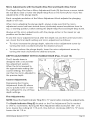
DEPTH=STOP ROD AND DEPTH=STOP TURRET (Figs. 16 and 17)
NOTE: The router motor
clamp
closed
depth
plunge
Fig. 16
should always be
securely when making
adjustments on the
base.
Control the cutting depth with
the Depth-Stop Rod and the
Depth-Stop Turret as follows:
1.
F
E
G
D
Turn the router motor off
C
and unplug the router from
the power source.
B
A
2.
Place the router, with the
cutting bit installed,
flat, level surface.
3_
on a
Lower the plunge action until the cutting
on which the router is sitting.
28084 Manual Revised 07-0712
bit makes contact
with the surface
Page 29
4.
Lock the Plunge-Depth
Locking Lever (F). This position is now "0" (zero), the
point from which further depth adjustments can be made.
5.
Rotate the depth-stop turret until the lowest step of the turret (A) is aligned
directly under the Depth-Stop Rod (B) (see Fig.16).
6.
Loosen the Depth-Rod Locking Knob (C) and lower the Depth-Stop
it contacts the lowest step on the turret.
7.
Slide the Clear Plastic Depth-Indicator
(D) until the red line on the indicator
is lined up with "0" (zero) on the bottom of the depth scale. This is now
indicating point at which the bit makes contact with the workpiece.
8.
To set a desired cutting depth, slide the Depth-Stop Rod up until the Red
Line on the Clear Plastic Depth-Indicator
points to the desired cutting depth
on the Depth Scale (E). Secure the Depth-Stop Rod at this position by
tightening the Depth Rod Locking Knob.
9.
Unlock the Plunge Lock Lever (F) to allow the bit to automatically
the UP position.
Rod until
retract to
10. The desired depth-of-cut
may now be achieved by plunging the router down
until the depth-stop
rod contacts the selected step on the depth-stop turret.
Making
Deep Cuts with the Depth=Stop
Turret (Fig. 17)
NOTE: Making a single,
deep cut is never advisable.
Smaller diameter cutting
bits are easily broken by too
much side thrust and torque.
Larger cutting bits will cause
a rough cut and be difficult to
guide and control. For these
reasons, do not exceed 1/8in. depth of cut in a single
pass.
To produce deep cuts, always
make several, progressively
deeper cuts by starting with
the Highest Step on the depthstop turret, and, after each cut, rotate the turret to the next lowest step until the
final Lowest or Last step is reached.
The 5 steps progress by 1/8th-in. increments. The 5 steps represent a range of 3/8
in. to 7/8 in. with a full 360 ° rotation of the turret. Repeat this process if necessary.
28084 Manual Revised 07-0712
Page 30
Micro Adjustments
with the Depth=Stop
Rod and Depth=Stop
Turret
The Depth-Stop Rod has a Micro Adjustment Knob (G) that turns a screw inside
the rod (B) to raise or lower the Depth-Stop Rod on the Turret (A) for micro-fine
adjustments of the plunge depth.
Each complete revolution
depth 5/127 inch.
of the Micro Adjustment
Knob adjusts the plunging
When micro-adjusting the plunge depth, always make sure that the microadjustment screw has been turned down (clockwise) several revolutions from its
top, or starting position, before setting the Depth-Stop Rod and Depth-Stop turret.
Always set the micro adjustments
position and locked down.
with the plunge action in the raised (or up)
To use the micro-adjustment
knob after the depth rod and the turret have been
set, check the final depth setting and micro adjustment as follows:
o
To micro-increase
the plunge depth, raise the micro-adjustment
turning the knob counterclockwise
the desired amount.
•
To micro-reduce
the plunge depth, lower the micro-adjustment
turning the knob clockwise the desired amount.
DEPTH ADJUSTMENT
The D-handle
WiTH D=HANDLE
base is
screw by
screw by
BASE (Figs. 18 and 19)
Fig. 18
designed with a micrometer
fine-adjustment
system.
When the bit is lowered to
the approximate setting (the
coarse setting), the system
can then be micro-adjusted
to
the precise depth.
Coarse
Adjustment:
Depressing the Coarse
Adjustment Knob (B) allows
you to quickly lower or raise
the cutting bit to one of three
depth settings.
N
Fine Adjustments:
NOTE: Reset the Depth Indicator Ring (E) to "0" (zero) before making fine adjustments.
The Depth indicator
Ring (E) located on the Fine Adjustment Dial is marked
in 1/64-in. increments. Turning the Fine Adjustment Dial clockwise 180 ° (1/2
turn), lowers the cutting bit 1/16-inch. One full turn clockwise (360 °) to "0" (zero)
lowers the bit 1/8-in.
28084 Manual Revised 07-0712
Page 31
The Depth Indicator Ring may be reset to "0" (zero) without moving the Fine
Adjustment Dial. This allows the user to begin adjustments from any reference point.
To Adjust Depth
1.
(Figs. 18 and 1;
Turn the router motor off
Fig. 19
and unplug the router from
the power source.
2.
Place the router, with the
cutting bit installed, on
a flat, level surface with
the back of the fixed base
facing you.
3.
4.
Open the Router-Motor
Clamp (A).
Press in Coarse
Adjustment Knob (B), and
lower the router motor into
the base until the cutting
base is sitting.
bit is very close to the flat surface on which the the
5.
Turn Fine Adjustment Dial (F) until the cutting
surface on which the base is sitting.
bit "just" touches
the flat
6.
Lock Router motor Clamp (A).
7.
While continuing to press the Coarse Adjustment Knob (B), turn the Fine
Adjustment Dial (F) until the "0" (zero) mark on the Depth Indicator Ring (E) is
lined up with the "1" mark on base.
8.
Release the Coarse Adjustment
line up with the "0" mark.
9.
Place the router on two, level, scrap workpieces, positioned side by side with a
space between them so that the cutting bit can be lowered below the sub-base.
Knob, making sure that the "0" continues
to
10. Turn the Fine Adjustment Dial (F) counterclockwise
to lower the bit to the
desired depth of cut. Turn the dial clockwise to raise the cutting bit.
11. Once the depth of cut is set, close the router motor clamp (A) securely.
NOTE: Making
bits are easily
cause a rough
exceed 1/8-in.
a single, deep cut is never advisable. Smaller diameter cutting
broken by too much side thrust and torque. Larger cutting bits will
cut and be difficult to guide and control. For these reasons, do not
depth of cut in a single pass.
28084 Manual Revised 07-0712
Page 32
Deep Cuts (Fig. 20)
Fig. 20
The proper cutting depth
for each pass is always
determined by the material,
the cutting bit size, and the
type and power of the motor.
Always make several,
progressively deeper cuts by
starting at one depth and then
making several more passes,
each time increasing the
cutting depth until the desired
depth is reached.
Making a cut that is too deep will stress the router motor and the cutting bit, and it
may burn the workpiece and dull the cutting bit. It could also "grab" too much of
the workpiece and cause loss of control of the router, causing a serious accident.
Always make test cuts in scrap material similar to the workpiece before
beginning the final cutting. Remember, knowing the right depth for each cut
comes with routing experience.
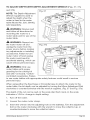
LED WORKLIGHTS
(Fig. 21)
The router motor has 3 built-
Fig. 21
in worklights located around
the collet/nut for high visibility
of workpiece when cutting.
These lights are always "ON"
when the toggle switch/trigger
switch is in the "ON" position,
28084
Manual
Revised
07-0712
Page 33
HEAVY-DUTY
EDGE GUIDE (Figs. 22, 22a and 22b)
The Router Combo comes
with a Heavy-Duty Edge
Guide. This edge guide
can be used as an aid in
routing applications such as
decorative edging, straight
edge planning and trimming,
grooving, dadoing and slotting.
To attach the edge guide to
the fixed, plunge, or D-handle
base, simply insert the edgeguide rods into edge-guide
mounting slots, adjust it to
the desired position, and lock
down with the edge-guide
locking knobs.
28084 ManuaLRevised 07-0712
Fig. 22a
Page 34
Electronic
Variable Speed Control
The electronic speed control
feature allows router motor
(Fig. 23)
Fig. 23
speed to be matched to cutter
size and workpiece-material
hardness for an improved
finish and extended bit life.
Speed changes are made by
rotating the Speed Control Dial
to the "LEFT," starting at "1 ,"
to increase the speed and to
the "RIGHT" to decrease the
speed, as indicated on the Dial.
The router motor top cap has
a "Variable Speed Selection
Chart" located above the "ON/OFF" toggle switch to help determine
speed for the cutting bit being used.
WARNING:
Before operating
the correct
the router follow all safety instructions
manual. Failure to do so could result in serious
personal
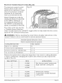
Variable Speed Selection
in this
injury.
Chart
Never exceed these bit speeds
Cutting-Bit
Diameter
Max. Speed
Up to 1 in. (25mm)
6
1-1/4 in. to 2 in. (30-50mm)
4 - 5
2-1/4 in. to 2-1/2 in. (55-65 mm)
2 - 3
3 in. to 3-1/2 in. (75-90mm)
1- 2
Reduce the speed when using extra large bits (1-inor more in cutting diameter
or heavy cutting bits. Changing the router's rate of feed can also improve the
quality of the cut.
DIAL SETTING
RPM
1
12,000
2
14,000
3
16,000
4
18,000
5
20,000
6
25,000
28084 Manual Revised 07-0712
APPLICATION
Non-ferrous metal, hardwoods,
larger diameter cutting bits
Softwoods,
plastics,
countertops, smaller diameter
cutting bits
Page 35
The speed charts above indicate the relationship between the speed setting and
the cutting application. Exact settings are determined through operator experience
and preference, and by recommendations
by the cutting-bit manufacturer.
ELECTRONIC
FEEDBACK
CIRCUITRY
Electronic feedback circuitry monitors and adjusts power in order to maintain the
desired RPM for consistent performance
and control, providing constant speed
under load for a quality finish in all materials
PLACING
,_
THE ROUTER
WARNING:
ONTO THE WORKPIECE
Before operating
AND STARTING
the router, follow all safety instructions
manual. Failure to do so could result in serious
personal
THE CUT
in this
injury.
NOTE: Making test cuts is essential with most routing applications. A test cut
will give a feel for the set-up, the router's speed, the depth of cut, and how the
cutting bit reacts to the workpiece.
Much of routing is a trial-and-error process of making various adjustments, followed
by test cuts. To avoid ruining good material, make test cuts on scrap materials.
28084 Manual Revised 07-0712
Page 36
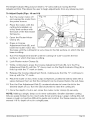
EDGE ROUTING
1.
(Figs. 24, 24a and 24b)
With the depth-of-cut set,
place the router on the
edge of the workpiece,
making sure that the
cutter does not contact
Fig. 24
the workpiece. (With the
plunge base, lock the
plunge action in the DOWN
position, ready to cut).
2.
3.
Have an edge guide
(or a board or a metal
straightedge) clamped
in place to help guide
router's base when making
the edge cut.
Fig. 24a
Turn the router "ON," and
allow the router motor to
reach the selected
speed.
4.
To begin the cut, gradually
feed the cutting bit into
the edge of the workpiece.
5.
When the cut is complete,
turn router motor "OFF"
and allow the cutting bit
come to a complete stop
before removing it from
the workpiece.
6.
Unplug the router from the
power source, place the
fixed base or D-handle
Fig. 24b
base and router upside
down on a worktable, and
inspect the finished cut.
Place the plunge router
on worktable, and inspect
finished cut in workpiece.
WARNING:
Always
securely clamp the workpiece
in place, and keep a firm grip
on the router base with both
hands at all times. Failure to
do so could result in loss of control causing
28084 Manual Revised 07-0712
possibly
serious personal
injury.
Page 37
,_
WARNING:
Removing the cutting
rotating could damage the workpiece
serious personal injury.
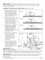
iNTERNAL
1.
2.
ROUTING
bit from the workpiece
while it is still
and result in loss of control, causing
WiTH FIXED BASE (Figs. 25, 25a, 25b)
With the depth-of-cut
set,
tilt the router and place
it on the workpiece with
only the leading edge of
the sub-base contacting
Fig. 25
_
o-_,
workpiece (Fig.25).
Turn the router motor "ON"
and allow the router motor
to reach the selected
speed, being careful not
to allow the cutting bit to
contact the workpiece.
3.
To begin the cut, gradually
lower the router until the
sub-base is level with the
Fig. 25b
workpiece to feed the
cutting bit into the workpiece
(see Fig 25a, 25b).
4.
When the cut is complete,
turn the router motor
"OFF" and allow the
Fig. 26
cutting bit come to a
complete stop before
removing it from the
workpiece.
5.
Unplug the router from
the power source, place
the router upside down
on the worktable, and
inspect the finished cut in
the workpiece.
,_
WARNING:
Always
securely clamp the workpiece
in place, and keep a firm grip on the router base with both hands at all times. Failure
to do so could result in loss of control, causing possibly serious personal injury.
,_
WARNING:
Removing the cutting
could damage the workpiece
personal injury.
28084 ManuaLRevised 07-0712
bit from workpiece
while it is still rotating
and result in loss of control, causing
serious
Page 38
NOTE: Making test cuts is essential with most routing applications.
A test cut
will give you a feel for the set-up, the router's speed, the depth of cut, and how
the cutting bit reacts to the workpiece.
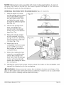
INTERNAL
1.
ROUTING
WITH PLUNGE
With the depth-of-cut set,
and the plunge action locked
in the raised (UP) position,
turn the router motor "ON"
and allow the router motor
BASE (Figs. 27 and 27a)
Fig. 27
to reach the selected speed
(see Fig. 27).
2.
Unlock the plunge-lock
lever and gently and
evenly lower the plunge
action into the workpiece.
(see Fig. 27a).
3.
When the plunge action
is fully lowered, lock the
plunge lock lever (DOWN)
and proceed to make the
cut (see Fig. 27a).
4.
Fig. 27a
When the cut is
completed, turn the router
motor "OFF" and allow
the cutting bit come to a
complete stop.
5.
When the cutting bit has
come to a complete stop,
unlock the plunge lock
lever (UP), and the plunge
action will automatically
retract the cutting bit from
the workpiece.
6.
Unplug the router from power source, place the router on the worktable,
inspect the finished cut in the workpiece.
,_
WARNING:
Always securely
clamp the workpiece
and
in place, and keep a firm
grip on the router base with both hands at all times. Failure to do so could result
in loss of control, causing serious personal injury.
28084 Manual Revised 07-0712
Page 39
NOTE: Making test cuts is essential with most routing applications. A test cut
will give you a feel for the set-up, the router's speed, the depth of cut, and how
the cutting bit reacts to the workpiece.
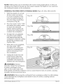
INTERNAL
1.
ROUTING
With the depth-of-cut
WITH D-HANDLE
set,
tilt the router and place
it on the workpiece with
only the leading edge of
the sub-base contacting
workpiece (Fig.28).
2.
Fig. 28
Turn the router motor "ON"
and allow the router motor
to reach the selected
speed, being careful not
to allow the cutting bit to
contact the workpiece.
3.
BASE (Figs. 28, 28a, 28b and 29)
To begin the cut, gradually
lower the router until the
sub-baee is level with the
Fig. 28a_
Fig. 28b
workpiece to feed the cutting
bit into the workpiece (see
Fig 28a, 28b).
4.
When the cut is complete,
turn the router "OFF"
and allow the cutting bit
come to a complete stop
before removing it from
the workpiece.
5.
Fig. 29
Unplug the routerfrom the
power source, place the
router upside down on the
worktable, and inspect the
finished cut in the workpiece.
_i_ WARNING:
Always
securely clamp the workpiece
in place, and keep a firm
grip on the router base with
both hands at all times. Failure to do so could result in loss of control,
possibly serious personal injury.
causing
_, WARNING: Removing the cutting bit from workpiece while it is still rotating
could damage the workpiece and result in loss of control, causing serious
personal injury.
28084 Manual Revised 07-0712
Page 40
,_
WARNING:
Removing the cutting
could damage the workpiece
personal injury.
bit from workpiece
and result in loss of control,
while it is still rotating
causing serious
NOTE: Making test cuts is essential with most routing applications.
A test cut
will give a feel for the set-up, the router's speed, the depth of cut, and how the
cutting bit reacts to the workpiece.
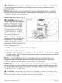
FREEHAND
,_
ROUTING
WARNING:
(Fig. 30)
Fig. 30
Do not use
large cutting bits for freehand
routing. Using large cutting
bits when freehand routing
could cause loss of control
or create other hazardous
conditions that could result
in personal injury. If using a
router table, large bits should
be used for edging only.
When used freehand, the
router becomes a flexible and
versatile tool. This flexibility
makes it possible to easily
rout signs, relief sculptures,
When freehand
etc.
routing:
1.
Draw or layout the pattern
2.
Choose
3.
Rout the pattern in two or more passes. Do not exceed 1/8-in. depth of cut in
a single pass. This will help provide better control, as well as serve as a guide
on the next passes.
the appropriate
on the workpiece.
bit.
NOTE: A core-box bit or V-groove bit is often used for routing letters and
engraving objects. Straight bits and ball mills are often used to make relief
carvings. Veining bits are used to carve small, intricate details.
NOTE: Making a single, deep cut is never advisable. Smaller-diameter
bits are
easily broken by too much side thrust and torque. Larger bits will cause a rough
cut and be difficult to guide and control. For these reasons, do not exceed 1/8in. depth of cut in a single pass.
_.
WARNING:
Always securely
clamp the workpiece
in place, and keep a firm
grip on the router base with both hands at all times. Failure to do so could result
in loss of control causing possible serious personal injury.
28084 Manual Revised 07-0712
Page 41
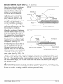
EDGING WITH A PILOT BiT (Figs. 31 and 31a)
Arbor-type bits with pilots are
excellent for edge shaping
any workpiece edge that is
straight or is curved with a
curvature that is equal to
or greater than the radius
of the bit that is used. The
pilot prevents the bit from
making a cut that is too deep;
holding the pilot firmly in
contact with the workpiece
edge throughout the cutting
process prevents the cut from
becoming too shallow.
When the workpiece thickness
and the desired depth of cut are
such that only the top part of
the edge will be shaped, leaving
at least a 1/16-in. thick uncut
Fig.31
Motor housing
\
TOP EDGE SHAPING
\
Workpiece
Top Edge of Workpiece
Fig. 31 a
portion below, the pilot can ride
against the uncut portion of the
workpiece. (See Fig. 31 .)
If the workpiece is too thin or
the bit is set so low so that
there will be no uncut edge
WHOLE EDGE SHAPING
Guide Board
against which to ride the pilot,
Whole Edge of Workpiece
an extra board must be placed
under the workpiece to act
as a guide (see Fig. 30a). This
"guide" board must have exactly the same shape as the workpiece edge. If it is
positioned so that its edge is flush with the workpiece edge, the bit will make a
full cut. If the guide board is positioned as shown in Fig. 15a (extending beyond
the workpiece edge), the bit will make less than a full cut, altering the shape of
the finished edge.
_.
WARNING:
Always securely
clamp the workpiece
in place, and keep a firm
grip on the router base with both hands at all times. Failure to do so could result
in loss of control causing possible serious personal injury.
28084 Manual Revised 07-0712
Page 42
FEEDING
THE ROUTER
(Fig. 32)
The secrets to professionallooking routing are careful setup for the cut, proper depthof-cut selection, knowing how
the cutting bit reacts in the
workpiece, and the rate and
direction of feed of the router.
DIRECTION
OF FEED =
EXTERNAL
CUTS (Fig. 32)
The router motor and cutting
bit rotate clockwise. This
Fig. 32
_
Router Feed
Direction
_'_
©
Rout
End
Grain:
First
1
(D
O
.-I=
_5
',.L_
Cutting
Bit
Router Feed
requires the feed of the cutting
@ Direction
bit to be from left to right (see
Fig. 32). Feeding the bit from
left to right will cause the bit to pull the router towards (up against) the workpiece.
If the router is fed in the opposite direction (right to left), the rotating force of the
cutting bit will tend to throw the bit away from the workpiece, making it hard to
control. This is called "Climb-Cutting:"
cutting in the opposite direction of the
proper feed direction. "Climb Cutting" increases the chance of loosing control,
resulting in possible personal injury. When "Climb Cutting" is required (backing
around a corner, for example), exercise extreme caution to maintain control of
the router.
KICKBACK
Because of the high speed of the cutting bit during a proper feeding operation
(left to right), there is very little kickback under normal conditions. However, if
the cutting bit strikes a knot, an area of hard grain in the workpiece, or a foreign
object, the normal cutting action could be affected and cause "Kickback."
This Kickback may cause damage to your workpiece, and could cause you to
lose control of the router, causing possible personal injury. Kickback is always
counterclockwise:
the opposite direction of the clockwise cutting bit rotation.
To guard against and help prevent Kickback, plan the
of feed so that the router is always moving, and keep the
cutting bit so that they are biting straight into new (uncut)
Also, always inspect the workpiece for knots, hard grain,
could cause a kickback problem.
28084 ManuaLRevised 07-0712
set-up and direction
sharp edges of the
wood (workpiece).
and foreign objects that
Page 43
DiRECTiON OF FEED =iNTERNAL CUTS (Figs. 33 and 33a)
When making an internal cut,
such as a groove, dado, or
slot, the edge guide, straight
edge, or board guide must
always be positioned on the
right-hand side of the router
as you make the cut (Fig. 33).
Fig. 33
Guide Outside
Bit Rotation
Thrust
When the guide is positioned
on the right hand side of
the router, the router travel
should be from left to right
and "counterclockwise"
Bit Rotation
Router Feed Direction
around curves (see Fig. 33).
This counterclockwise
action
around the curve could cause
"Climb cutting". Always be
alert and exercise extreme
caution to maintain control of
Guide
Fig. 33a
Guide inside
the router when making this
type of cut around curves.
When the guide is positioned
as shown in Fig. 33a, the
router travel should be from
left to right and clockwise
around curves.
Bit Rotation
\
/
=Thrust
Guide
Bit Rotation
/
If there is a choice, the setRouter Feed Direction
up in Fig. 33 is easier to use,
but there is the possibility of
"Climb Cutting" around curves. In either case, Fig. 30 or Fig. 33a, the sideways
thrust of the router cutting is always against the guide, as is proper.
_1_ WARNING:
Always securely
clamp the workpiece
in place, and keep a firm
grip on the router base with both hands at all times. Failure to do so could result
in loss of control causing possible serious personal injury.
28084 Manual Revised 07-0712
Page 44
RATE OF FEED (Figs. 34 and 34a)
The proper rate of feed
depends on several factors: the
hardness and moisture content
Fig. 34
of the workpiece, the depth of
cut, and the cutting diameter of
the bit. When cutting shallow
grooves in soft woods such as
pine, you may use a faster rate
of feed. When making deep
cuts in hardwoods such as oak,
you should use a slower rate
of feed.
Cut
TOO FAST
Cutter
FEEDING TOO RAPIDLY (Fig. 34)
Clean and smooth finished
cuts can only be achieved
when the cutting bit is rotating
at a relatively high speed
and taking very small bites,
producing tiny, clean-cut chips.
Fig. 34a
Cut
Forcing the feed of the cutting
bit forward too rapidly slows
the RPM of the cutting bit, and
the bit takes larger bites as it
rotates. Larger bites mean larger
chips and a rough finish. This
forcing action can also cause
the router motor to overheat.
TOO SLOW
Cutter
Under extreme force-feeding
conditions, the RPMs can become so slow and the
bites become so large that chips become partially cut off, causing splintering
and gouging of the workpiece.
The router will make clean, smooth cuts if it is allowed to run freely without the
overload of forced feeding. You can detect forced feeding by the sound of the
motor. Its usual high-pitched
whine will sound lower and stronger as it loses
speed. Holding the router against the workpiece will also be more difficult to do.
FEEDING
TOO SLOWLY (Fig. 34a)
When you feed the cutting bit too slowly, the rotating cutting bit does not cut into
new wood rapidly enough to take a bite. Instead, it scrapes away sawdust-like
particles. This scraping produces heat, which can glaze, burn, and mar the cut in
the workpiece and, in extreme cases, overheat the cutting bit.
When the cutting bit is scraping
control as you feed it.
28084 Manual Revised 07-0712
instead of cutting,
the router is more difficult
to
Page 45
With almost no load on the motor, the cutting bit has a tendency to bounce
off the sides of the cut in the workpiece, producing a cut with a rippled finish
instead of clean, straight sides.
CHIP SHIELDS
(Figs. 35, 35a and 35b)
_1_ WARNING:
Always wear
eye protection. The chip
shields are not intended as
safety guards.
,_ WARNING: Always turn
the router motor off and
unplug the router from its
power source before making
any adjustments or installing
accessories. Failure to turn the
router motor off and unplug
the router could result in
Fixed Base
Tabs
accidental starting, which can
cause serious personal injury.
To remove the chip shield from
the fixed base, press inward
on the tabs until the chip
shield releases from the base,
Fig. 35a
and remove the chip shield. To
attach the chip shield, place
the chip shield in position, and
flex the sides while pushing
it in, until it snaps back into
place (See Fig. 35).
The chip shield on the plunge
base is held in position by
Plunge Base
Screw
a screw. To remove the chip
shield from the plunge base,
simply remove the screw and take the chip shield off the base (See Fig. 35a).
28084 ManuaLRevised 07-0712
Page 46
To remove the chip shield from the D-handle base, press inward on the tabs until the
chip shield releases from the base and remove the chip shield. To attach, place chip
shield in position, and flex sides while pushing it in until it snaps back into place (See
Fig. 35b).
_,
WARNING:
The chip
shield deflectors help keep
dust and chips away from the
operator; they will not stop
objects larger than woodchips
thrown from the bit.
CAUTION:
Always have
the chip shield deflector
in place on the base when
operating the router.
D-handle Base
DUST EXTRACTION
Tabs
HOODS
(Figs. 36, 36a and 36b)
Two dust-extraction
hoods
included with the three router
bases. Each hood is sized to
Fig. 36
accept a 14/4-in. vac hose
adapter, sold separately.
Dust Extraction
Hood for
Fixed Base (Fig. 36)
To attach the hood onto the
fixed base, align the two tabs
on the hood with the two slots
on the port at back of the
base, and secure it by turning
it clockwise (Fig. 36).
28084 Manual Revised 07-0712
Page 47
Dust Extraction
Hood for Plunge Base (Fig. 36a)
To attach the hood onto the
Fig. 36a
plunge base, position and
secure it to the back of the base
with the two screws (included),
as shown in Fig. 36a.
The dust extraction hood can
also be installed with the hose
outlet facing the front of the
plunge base by removing the
chip shield and attaching the
hood at the front of the base.
Dust Extraction
Handle
Hood for D=
Tow Screws Included
Base (Fig. 36b)
To attach the hood onto the
Fig
---'_"
D-handle base, align the two
tabs on the hood with the
two slots on the port at back
of the base, and secure it by
turning it clockwise (Fig. 36b).
WARNING: Always turn
the router motor off and
unplug the router from the
power source before making
any adjustments or installing
accessories. Failure to turn
router motor off and unplug
the router could result in
accidental
starting,
which can cause serious
28084 Manual Revised 07-0712
personal
injury.
Page 48
TO ADJUST
DEPTH WITH DEPTH=ADJUSTMENT
and 37b)
WRENCH
(Figs. 37, 37a
Fig. 37
NOTE: The Depth-Adjustment
Wrench supplied is used to
adjust the depth when the
router is fixed to the router
table (Model No. 320. 28180),
sold separately.
WARNING: Always
and follow all directions
read
for
mounting the router to a
router table and for use of the
router table.
A
WARNING: Always turn
the router motor off and
Fig. 37a
unplug the router from the
power source before making
any adjustments or installing
accessories.
Failure to turn
router motor off and unplug
the router could result in
accidental starting, which can
cause serious personal injury.
_,
WARNING:
Only use
router tables with proper
guarding for the cutting bit
and with "on-board,"
switchcontrolled receptacles. Failure
to use router tables with appropriate
personal injury.
safety features
could result in serious
When using either the fixed base or D-handle base to attach the router to the
router table, the bit depth can be adjusted by turning the Micro Adjustment Dial
clockwise or counterclockwise
with the wrench supplied. (Fig. 37 and Fig. 37a)
The depth of the cut can be read on the scale dial. Each mark on the scale
indicates a 1/64-in. change in depth setting.
1.
Turn off the router.
2.
Loosen the router motor clamp.
3.
Insert the wrench into the adjusting hole on the tabletop. Turn the adjustment
bolt on the router clockwise with the wrench to move the collet/nut up, or
counterclockwise
to move the collet/nut down.
28084 Manual Revised 07-0712
Page 49
4.
When the desired depth
of cut is set, tighten the
clamping lever.
Fig. 37b
The precise depth of cut can
be measured with a ruler.
When using the plunge base
to attach the router to the
router table, the bit depth
can be adjusted by turning
the depth rod clockwise or
counterclockwise
with the
wrench supplied
(Fig. 37b).
1.
Turn off the router.
2.
Lock the Plunge Depth Locking
3.
Insert the wrench into the adjusting hole on the tabletop. Turn the depth
rod on the router clockwise with the wrench to move the collet/nut up, or
counterclockwise
to move the collet/nut down.
4.
When the desired
Lever.
depth of cut is set, tighten the clamping
The precise depth of cut can be measured
28084 ManuaLRevised 07-0712
lever.
with a ruler
Page 50
WARNING:
by a qualified
To ensure safety and reliability, all repairs should be performed
service technician
at a Sears Service Center.
GENERAL
Only the parts shown on the parts list are intended for repair or replacement by
the customer. All other parts represent an important part of the double-insulation
system and should be serviced only by a qualified Craftsman service technician.
_,
WARNING:
For your safety, Always turn off the switch and unplug the router
motor from the power source before performing
any maintenance
or cleaning.
It has been found that electric tools are subject to accelerated wear and possible
premature failure when they are used to work on fiberglass boats and sports
cars, wallboard, spackling compounds or plaster. The chips and grindings from
these materials are highly abrasive to electrical tool parts, such as bearings,
brushes, commutators,
etc. Consequently, it is not recommended
that this tool
be used for extended work on any fiberglass material, wallboard, spackling
compound, or plaster. During any use on these materials, it is extremely
important that the tool is cleaned frequently by blowing with an air jet.
_1_ WARNING:
Always wear safety goggles or safety glasses with side shields
during power tool operations,
wear a dust mask.
ROUTINE
or when blowing dust. If operation
is dusty, also
MAINTENANCE
A
WARNING: Do not at any time allow brake fluids, gasoline, petroleum-based
products, penetrating oils, etc. come in contact with plastic parts. Chemicals can
damage, weaken, or destroy plastic, which may result in serious personal injury.
•
When work has been completed,
of the tool over time.
clean the tool to allow smooth
functioning
o
Use clean, damp cloths to wipe the tool.
•
Check the state of all electrical
•
Keep the router-motor air openings free from oil, grease, and sawdust
woodchips, and store the tool in a dry place.
•
Be certain that all moving parts are well lubricated,
exposure to damp and/or dirty conditions.
•
For collet/nut
,_
WARNING:
cables.
care, see the Operation
section
particularly
or
after lengthy
of this manual
For your safety, always turn off the switch and unplug the router
motor from the power source before performing
Refer to "Collet/Nut
Care and Cutting
28084 Manual Revised 07-0712
any maintenance
or cleaning.
bits" for cleaning care.
Page 55
REPLACEMENT
OF CARBON
Replacement brush sets are
available through Craftsman
Parts and Repair Centers.
1.
Unplug the router motor
before inspecting or
replacing brushes.
2.
Replace both carbon
brushes when either has
BRUSHES
(Fig. 38)
Fig. 38
less than 1/4-in. length of
carbon remaining, or if the
spring or wire is damaged
or burned.
Ears
Brushes
3.
Using a slotted
screwdriver, remove the black, plastic cap on each side of the router motor
(Fig. 38), and carefully withdraw the spring-loaded
brush assemblies. Keep
brushes clean and sliding freely in their guide channels.
NOTE: To reinstall the same brushes, make sure that the brushes go back in the
same way they came out. This will avoid the need for a break-in period.
4.
Insert new brush assemblies into the guide channels with the carbon part
going in first, being certain to fit the two metal "ears" into their slots in the
channel (Fig. 38).
5.
Remember to replace both end caps after inspecting or servicing brushes.
Tighten the caps snugly, but do not over-tighten. The router should be
allowed to "RUN IN" (run at no load without a cutting bit) for 5 minutes before
use to seat the new brushes properly.
WARNING:
For your safety, always turn off the switch and unplug the router
motor from the power source before performing
any maintenance
or cleaning.
LUBRiCATiON
All of the bearings in this tool are lubricated with a sufficient amount of highgrade lubricant for the life of the tool under normal operating conditions.
Therefore, no further lubrication is required.
28084 Manual Revised 07-0712
Page 52
Trouble
I -The router does not
work
Probable
Cause
-Plug is not plugged into
the power source.
-Plug the detachable cord
into the power source.
*Plug is not plugged into
the Router socket.
• Plug the detachable
into the Router.
*Switch
tion.
• Pull the switch to "ON"
is in "OFF" posi-
*The carbon brushes
have worn out completely.
• The surface of the
work piece is not
smooth after cutting
*Bit can not be
installed
28084 Manual Revised 07-0712
Solution
cord
position.
• Open the brush cap, and
replace the old brushes with
suitable new brushes.
*The bit is dull.
• Change to a sharp bit.
-Routing at an inappropriate bit speed.
-Refer to "Variable Speed
Selection Chart" label on
the Router Motor cap, and
select an appropriate bit
speed.
*Bit size is inappropriate
for the collet/nut
• Use only 1/2 in. or 1/4 in.
diameter bits.
Page 53
WARNING:
recommended
The use of attachments
or accessories
for this tool might be dangerous
that are not
and could result in serious
Sears and other Craftsman outlets offer a large selection
accessories designed for specific routing applications.
There is a large selection
bits available in High-Speed
Craftsman
RouterTipped
Cutting
Steel
or Carbide
High-Speed Steel for all your
[_
3/8-in.
_
1/4-in.
H
straight
[;
L4J
straight
_ straight
_
straight 3/4-in.
5/16-in.
#1 1/2-in.
_ straght _J, straight
straight
3/8-in. dove taim
1/2-in. dove tail
round nose
1/2-in. 90 d v groove
v groove
3/8x1/2-in.
flush trim
1/2-in,
flush trim
flush trim
1/4-im
flush trim
3/8-in. keyhole
1/2-in,
cove
round over
3/8 in
}
dovetail
1/2-in.round nose
1/2 x 1-in.
fmush trim
28084 Manual Revised 07-0712
router
of
1/8-in.
routing needs.
of Craftsman
injury.
1/4-in,
keyhole
cove
round over
round over
_
1/8 in
round
over
1/4
i_
q
cove
1/2 in
round
over
Page 54
In addition to a wide variety
of router bits, Sears also
offers accessories such
as: Router tables, various
template sets, universal
router fence with lock knobs
bead and cove
q_
1/16-in.
classic cove
with bead
_
1/4-in. roman ogee
(64181), 11 pc. bushing set
(64180) and clear sub-base
sets; 6pc. fixed base (64182)
6 pc. plunge base (64183).
-_-_
bead cove
classic cove & bead
Roman ogee
_3
3/8-in,
,_k WARNING:
_._<_
1/2-in.
rabbeting
rabbeting
Only use
router tables with proper
guarding for the cutting bit
and with "on-board"
switch
1/4-in,
veining
controlled receptacles.
Failure to use router tables
veining
with appropriate safety
features could result in
serious personal
injury.
1/2-in. core box
1/2-in. mortising
core
box
mortising
l ]
1/4-in. panel pilot
1 3/8-in, 45° chamfer
28084 Manual Revised 07-0712
panel pilot
chamfer
Page 55
12.5 Amp / Variable
Speed / 2= 1/4 Peak HP MODEL
NUMBER
320.28084
The Model Number will be found on the Nameplate.
Always mention the Model Number
Router Motor
Unit
in all correspondence
regarding
your tool.
1_
22J/
23j
i
j23
241J
!
25"/_
_
l
27JJ
i
__26
28_
54
28084 Manual RevisedO7-O712
Page56
12.5 Amp / Variable
The Model
Speed / 2=1/4 Peak HP MODEL
NUMBER
320.28084
Number will be found on the Nameplate.
Always mention the Model Number
in all correspondence
regarding
your tool.
FIXED BASE
28084 Manual Revised 07-0712
Page 57
12.5 Amp / Variable Speed / 2=1/4 Peak HP Fixed Base Router MODEL
NUMBER 320.28084
The Model Number will be found on the Nameplate.
Always mention the Model Number
in all correspondence
regarding"
tool.
_63
-'--64
"---65
"---66
_---68
--70
--71
1-72
84
_86
89
91
93
98
28084 Manual Revised 07-0712
Page 58
12.5 Amp / Variable
The Model
Speed / 2=1/4 Peak HP MODEL
320.28084
Number will be found on the Nameplate.
Always mention the Model Number
D=HANDLE
NUMBER
in all correspondence
regarding
your tool.
BASE
-125
I05,
134
135
-I 36
1
111
118
14t
28084
ManuaLRevised
0L0712
Page 59
12.5 Amp / Variable
Speed / 2=1/4 Peak HP MODEL
NUMBER
320.28084
The Model Number will be found on the Nameplate.
Always mention the Model Number
in all correspondence
regarding
your tool.
ACCESSORIES
142
152
r152
\154
28084
Manual
Revised
O7-O712
Page 60
12.5 Amp / Variable
BER 320.28084
Speed / 2=1/4 Peak HP Fixed Base Router MODEL
NUM=
The Model Number will be found on the Nameplate.
Always mention tool's model number when ordering parts.
Motor Unit
1
3703841000
Decorate Cover
1
2
3123313000
Transparent Cap
1
3
5610220000
Thread Forming Screw
2
4
3123278000
Rear Cover
1
5
5610017000
Tapping Screw
2
6
4900256000
Speed Adjustor
1
7
5620017000
Hexagon Socket Screw
2
8
5610059000
Thread Forming Screw
2
9
4540017000
Power Indicator
1
10
3123329000
Lock Ring
2
4870073000
Switch
1
4930008000
Sleeve
2
4930038000
Receptacle
2
12
3122851000
Seal Ring
1
13
3120537000
Brush Cap
2
14
2800005000
Brush Holder
2
15
4960019000
Carbon
2
16
2822257000
Power Cord ASSY
1
4930314000
Receptacle
1
4930008000
Sleeve
2
4930038000
Receptacle
2
18
3123279000
Middle Housing
1
19
3520130000
Bearing Holder
1
20
3121049000
Rubber Ring
1
21
3700249000
Washer
1
22
2740240000
Stator
1
23
5610065000
Tapping Screw
2
11
17
28084
Manual
Revised
07-0712
Light
Brush
Page 61
2750839000
Rotor
1
5700008000
Ball Bearing
1
25
3123280000
Fan Baffle
1
26
5620040000
Screw
3
27
2822255000
LED Holder ASSY
1
28
5700056000
Ball Bearing
1
29
3420557000
Motor Housing
1
30
3550855000
Spindle Lock
1
31
5660005000
E Ring
1
32
3660174000
Stop Spring
1
33
5630179000
Nut
1
5630187000
Collet Nut
1
3550721000
Collet
1
35
5620041000
Screw
1
36
3320460000
Adjusting
37
3123281000
Indicator
1
38
3550854000
Shaft
1
39
3320274000
Handle
2
40
5620024000
Hexagon Socket Screw
2
3420558000
Mounting
1
5670040000
Located
42
3121637000
Chip Shield
1
43
3703872000
Plate
1
3703863000
Clamping
5670026000
Pin
1
24
34
Fixed Base
41
44
Knob
Pin
Lever
1
1
1
3550577000
Mitre Lock Bolt
1
45
3123651000
Rubber Insert
1
46
5620064000
Screw
1
47
3420562000
Adjustor
48
3123282000
Button
1
49
3660293000
Spring
1
50
2822361000
Sliding Block
1
28084 ManuaLRevised 07-0712
Block
1
Page 62
5630015000
Prevailing Torque Hexagon Nut
1
52
3700352000
Washer
1
53
5650172000
Wave Washer
1
54
5660005000
E Ring
1
55
3400189000
Lock Bolt
2
56
3123294000
Dust Bracket
1
57
5620067000
Screw
1
58
3122924000
Base Plate
1
59
5620049000
Screw
3
Plunge Base
60
3123338000
Lock Cap
2
61
3123337000
Knighthead
2
62
3660312000
Spring
2
63
5620032000
Screw
I
,
2
,
64
3123435000
65
5650014000
Plain Washer
1
66
3660313000
Spring
1
67
3550913000
Depth Stop Bar
1
68
3703949000
i Adjusting
I
1
Knob
•
1
i Chp
69
3123453000
Sleeve
70
3123756000
Sleeve
1
71
3123434000
Depth Indicator
1
72
3550083000
Depth Adjusting
73
3400189000
Lock Bolt
74
3123498000
75
5630016000
Hexagon Nut/1
1
76
3123497000
Cover
1
3420566000
Plunge Frame
1
3520261000
Bush
1
3520260000
Bush
1
5670040000
Located
78
3320274000
Handle
2
79
5620024000
Hexagon Socket Screw
2
77
28084
Manual
Revised
07-0712
Bolt
1
1
3
1
I Cap
Pin
1
Page 63
80
5640045000
Bolt
1
81
3660254000
Torsion Spring
1
82
3420398000
Plunge Lock Lever
1
83
5650007000
Spring Washer
1
84
5620039000
Screw
1
5670026000
Pin
1
3703863000
Clamping
Lever
1
3550577000
Mitre Lock Bolt
1
86
3703872000
Plate
1
87
5630015000
Prevailing Torque Hexagon Nut
1
88
5690138000
O Ring
1
89
5620103000
Slotted Shoulder Screw
2
90
3700078000
Wave Washer
1
91
3420570000
TurnTable
1
92
3700191000
Cap
1
93
3660274000
Spring
1
94
5660139000
E Ring
1
3420567000
Mounting
1
3550870000
Plunge Rod
1
3550869000
Long Plunge Rod
1
85
95
5670010000
Spring Pin
2
96
5650023000
Plain Washer
1
97
3550929000
Bolt
1
98
3122923000
Base Plate
1
99
5620049000
Screw
3
D-Handle
Base
100
3123329000
Lock Ring
2
101
2822345000
Internal Wire ASSY
1
102
3121064000
Cord Guard
1
103
3320518000
Switch Trigger
1
104
4870349000
Trigger Switch
1
105
3123513000
Switch
1
106
3320516000
Left Handle Cover
28084 ManuaLRevised 07-0712
Button
1
Page 64
107
3123530000
Cord Guard
1
108
5610106000
Tapping Screw
2
109
3120234000
Cord Anchorage
1
110
3320517000
Right Handle Cover
1
Tapping Screw
4
Tapping Screw
1
Tapping Screw
3
111
5610106000
112
5610031000
I
113
5610060000
114
4930004000
115
3121475000
Left Power Indicator
1
116
2822388000
Internal Wire ASSY
1
117
3121424000
Right Power Indicator
1
4930314000
Receptacle
1
4930064000
Shark Teeth Terminal
2
119
5620041000
Screw
1
120
3320460000
IAdjusting
121
3123281000
Indicator
1
122
3550854000
Shaft
1
123
3121637000
118
124
125
I Connector
1
Knob
i Chip Shield
1
1
1
3420587000
Mounting
5670040000
Located
5670026000
Pin
1
3550577000
Mitre Lock Bolt
1
3703863000
i Clamping
Pin
Lever
1
1
126
3703872000
Plate
1
127
5630015000
Prevailing Torque Hexagon Nut
1
128
3402219000
Front Handle
1
129
5660005000
E Ring
1
130
3400189000
Lock Bolt
2
131
5620064000
Screw
1
132
3123651000
Rubber Insert
1
133
3420562000
IAdjustor
134
3660293000
Spring
135
2822361000
28084
ManuaLRevised
07-0712
Block
i Sliding Block
1
1
1
Page 65
3700352000
Washer
1
137
3123282000
Button
1
138
3123294000
Dust Bracket
1
139
5620067000
Screw
1
140
3122924000
Base Plate
1
141
5620049000
Screw
3
Accessories
142
5620050000
Screw
2
143
5650015000
Spring Washer
2
144
5650013000
Plain Washer
2
145
3703925000
Fence
1
146
3550588000
Guiding Rod
2
147
3700807000
Wrench
1
5630187000
Collet Nut
1
3550595000
Collet
1
149
3123286000
Vaccum Adapter
1
150
3402220000
151
3123344000
Chip Shield
1
152
5620353000
Knurled Thumb Screw
2
153
3123454000
Vaccum Adapter
1
154
3123500000
148
28084 ManuaLRevised 07-0712
Depth Adjusting
Support
Lever
Plate
1
1
Page 66
28084
Manual
Revised
07-0712
Page 67
Your Home
For repair - in your home - of all major brand appliances,
lawn and garden equipment, or heating and cooling systems,
no matter who made it, no matter who sold it!
For the replacement parts, accessories and
owner's manuals that you need to do-it-yourself.
For Sears professional installation of home appliances
and items like garage door openers and water heaters.
1-800-4-MY-HOME ®
(!-800-469-4663)
www.sears.eom
Call anytime, day or night
(U.S.A and Canada)
www.sears.ca
For expert home solutions advice: www.managemyhome.com
Our Home
For repair of carry-in products like vacuums, lawn equipment,
and electronics, call or go on-line for the nearest
Sears Parts & Repair Service Center
1-800-488-1222
(U.S.A.)
1-800-469-4663
(Canada)
Call anytime, day or night
www.sears,com
www.sears.ca
To purchase a protection agreement on a product serviced by Sears:
1-800-827-6655
(US.A.)
Para pedir servicio de reparacion
a domicilio, y para ordenar piezas:
1-888-SU-HOGAR®
(1-888-784-6427)
1-800-361-6665 (Canada)
Au Canada pour service en fran£ais:
1-800-LE-FOYER Mc
(1-800_533-6937)
www.sears ca
© Sears Brands, LLC
® Registered Trademark / TMTrademark / SMService Mark of Sears Brands, LLC
® Marca Registrada / TMMarca de Fabrica / sN Marca de Servicio de Sears Brands, LLC
MCMarque de commerce / MDMarque deposee de Sears Brands, LLC