1
SoftSoft
FAX / MODEM
USER'S GUIDE
Ver 1.0
The information in this document is subject to change without notice and does not represent a commitment on the
part of the vendor.
No warranty of representation, either expressed or implied, is made with respect to the quality, accuracy or fitness
for any particular purpose of this document. The manufacturer reserves the right to make changes to the content
of this document and/or the products associated with it at any time without obligation to notify any person or
organisation of such changes.
In no event will the manufacturer be liable for direct, indirect, special, incidental or consequential damages arising
out of the use or inability to use this product or documentation, even if advised of the possibility of such damages.
Microsoft Windows is a trademark of Microsoft Corporation.
All product names are trademarks or registered trademarks of their respective owners.
FCC Compliance Statement
This device complies with Part 15 and 68 of the FCC Rules. Operation is subject to the following two conditions:
1. this device may not cause harmful interference, and
2. this device must accept any interference received, including interference that may cause undesired
operation.
FCC Warning Statement
This equipment has been tested and found to comply with the limits for a Class B digital device, pursuant to Part
15 and 68 of the FCC Rules. These limits are designed to provide reasonable protection against harmful interference
in a residential installation. This equipment generates, uses and can emit radio frequency energy and, if not installed
or used in accordance with the instructions, may cause interference to radio communications. However, television
reception interference can be determined by turning the equipment off and on, the user is encouraged to correct
the interference by one or more of the following measures:
•
•
•
•
Reorient or relocate the receiving antenna
Increase the separation between the equipment and the receiver
Connect the equipment into an outlet different from that to which the receiver is connected
Consult the dealer or an experienced radio/TV technician for help.
F
Changes or modifications not expressly approved by the party responsible for compliance could
void the user’s authority to operate the equipment
The information contained in this manual has been verified at the time of this
manual's printing. The manufacturer reserves the right to make any change and
improvement in the product described in this manual at any time and without
notice.
All registered trademarks are the property of their respective owners.Copyright
©1999 All rights reserved. No reproduction of this document in any form is
permitted without prior written authorization from the manufacturer.
Version 1.0
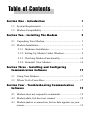
Table of Contents
Section One - Introduction
1
1.1 System Requirements ......................................................... 1
1.2 Modem Compatibility ......................................................... 1
Section Two - Installing The Modem
3
2.1 Unpacking Your Modem ..................................................... 3
2.2 Modem Installation ............................................................. 3
2.2.1 Hardware Installation .............................................. 3
2.2.2 Setting Up Modem Under Windows ....................... 4
2.2.3 Checking Modem Functionality ............................ 14
2.2.4 Uninstall Your Modem ......................................... 16
Section Three - Installing and Configuring
Communication Software
17
3.1 Using Your Modem ........................................................... 17
3.2 Where To Go From Here .................................................. 17
Section Four - Troubleshooting Communication
Software
19
4.1 Modem does not respond to commands. .......................... 19
4.2 Modem dials, but does not connect. ................................. 19
4.3 Modem makes a connection, but no data appears on your
screen. ............................................................................... 19
4.4 Modem experiences errors while online with a remote
modem. ............................................................................. 19
4.5 Modem exhibits poor voice record or playback. .............. 19
Section Five - AT Command Set
19
5.1 Executing Commands ....................................................... 21
5.2 Command Format ............................................................. 21
5.3 AT Commands: Basics ...................................................... 21
5.4 +++ (Plus-Plus-Plus) commands ...................................... 22
5.5 AT and AT& (Ampersand)Commands ............................. 22
5.6 AT% (Percent) and AT\ (Backslash) Commands.............. 25
5.7 AT* (Asterisk) Commands ............................................... 28
5.8 AT+ (Plus) Commands ..................................................... 29
Section Six - S Register Summary
39
Section Seven - Event Reporting Word
40
1
Section One - Introduction
Your new 56Kbps modem is a high speed PC communication peripheral that
combines Data, Fax, Voice and Speakerphone functions into a single device.
This high performance modem connects your computer to all popular modems
and fax machines available today.
This manual provides installation and operating instructions for your
modem. Also included in this manual are listings and descriptions of the
standard AT command set, S-registers, and troubleshooting tips. Be certain to
read Section Two - Installing the Modem thoroughly before performing the
actual installation. Our customer support experience has shown that many
costly and time-consuming calls can be avoided with closer attention to the
installation information provided here.
1.1 System Requirements
n
n
n
n
n
n
Pentium 166 MHz with MMX
AMD K6 or K6-2 233 MHz
Cyrix 6x86MX 266 MHz
16MB RAM
256K L2 cache
Windows 95 OSR2, Windows 98
1.2 Modem Compatibility
Your modem is compatible with the following standards:
• V.90 (56Kbps down stream only)
• K56 flex (56kbps download stream only)
• V.34 (33600 bps)
• V.32bis (14400 bps)
• V.32 (9600 bps)
• V.23 (1200/75 bps)
• V.22bis (2400 bps)
• V.22 (1200 bps)
• V.21 (300 bps)
• Bell 212A (1200 bps)
• Bell 103 (300 bps)
• V.17 (14400 bps FAX)
• V.29 (9600 bps FAX)
• V.27ter (4800 bps FAX)
• V.21 Channel-2 (300 bps FAX)
• V.42bis (data compression)
• V.42 (error correction)
• MNP 5 (data compression)
• MNP 2-4 (error correction)
• TIA/EIA 602 AT Command set
2
• V.8 Start-up sequence
• V.80(Video Ready mode)
• V.8 bis Start-up sequence
• Plug and Play PCI Spec. V1.0a
• TIA/EIA 695 Voice command
• TIA/EIA578 Class 1 Fax Command Set
3
Section Two - Installing The Modem
This section explains how to connect your modem to your computer.
2.1 Unpacking Your Modem
In addition to this manual, your modem package contains the following
items:
•One modem
• Modem software & driver disc
•manual include in Disc
• One telephone cable
NOTE: Contact your dealer if any of the above items are
missing from your package.
2.2 Modem Installation
The following steps provide instructions for installing your modem.
2.2.1 Hardware Installation
CAUTION: Before removing the cover from your
computer, turn off and unplug the computer and all
attached peripherals. Discharge any static electricity
from your body by touching any metal surface before
removing the modem from its antistatic bag.
1. Turn off and unplug your computer from the AC outlet.
2. Remove the computer's cover according to its owner's manual.
3. Select any available PCI bus slot.
4. Remove the bracket and save the screw.
5. Carefully insert the modem into the selected slot. Apply even
pressure until the modem is firmly seated.
6. Secure the bracket with the screw saved earlier. Store the bracket for
future use.
4
7. Replace the computer cover
and plug in your computer.
Reconnect all cables.
1
2
4
3
5
7
*
8
0
6
9
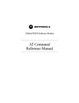
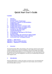
8. Connect the telephone able
into the modem's "LINE" connector (see Figure 2-1). Attach
the other end into the telephone wall jack.
This completes the internal modem installation.
Figure 2-1
NOTE: The back of your modem should look like Figure
2-1.
2.2.2 Setting Up Modem Under Windows
This internal modem supports the Plug and Play feature. It allows your
computer to set the optimal configuration for the modem and communication
software automatically.
PART A WIN 98
Please follow the procedure below to install the modem driver:
1. Turn ON computer power after completing hardware installation.
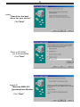
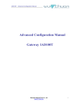
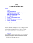
2. Windows 98 will automatically detect the Plug and Play modem and
setup a "Motorola SM56 PCI Speakerphone Modem" message under
Add New Hardware Found as shown below.
Auto detect
"PCI Communication
Device"
Click "Next"
5
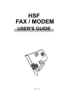
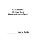
select
"Search for the best
driver for your device"
Click "Next"
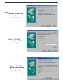
Direct to CD-ROM
(ex. E:\Drivers\W98)
Click "Next"
search to
"Motorola SM56 PCI
Speakerphone Modem
"
Click "Next"
6
Direct to CD-ROM
(ex. E:\Drivers\W98)
Click "OK"
Click "OK"
Click "Finish"
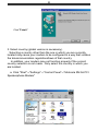
Add to
"Wave Device for
Voice Modem"
Click "Next"
7
select
"Search for the best
driver for your device"
Click "Next"
Direct to CD-ROM
(ex. E:\Drivers\W98)
Click "Next"
search to
"Motorola SM56
Modem Serial Wave
Device"
Click "Next"
8
Click "Finish"
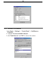
3. Select country (global version is necessary).
Selecting a country other than the one in which you are currently
located may cause your modem to be configured in a way that violates
the telecommunication regulations/laws of that country.
In addition, your modem may not function properly if the correct
country selection is not made. Only select the country in which you
are located.
a. Click "Start"⇒"Settings"⇒"Control Panel"⇒"Motorola SM 56 PCI
Speakerphone Modem"
9
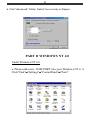
b. Click "Advanced" Folder. Select Your country or Region.
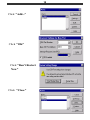
PART B WINDOWS NT 4.0
Under Windows NT 4.0
a. Please add a new COM PORT into your Windows NT 4. 0
Click"Start"⇒"Settings"⇒"ControlPanel"⇒"Ports"
10
Click "Add..."
Click "OK"
Click "Don't Restart
Now"
Click "Close"
11
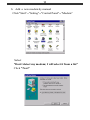
b. Add a new modem by manual
Click "Start"⇒"Setting"⇒"Control Panel"⇒"Modem"
Select
"Don't detect my modem; I will select it from a list"
Click "Next"
12
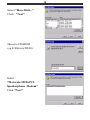
Select "Have Disk..."
Click "Next"
Direct to CD-ROM
(eg. E:\Drivers\NT40)
Select
"Motorola SM56 PCI
Speakerphone Modem"
Click "Next"
13
C. Please assign this modem on the new COM PORT
Click "Next"
Click "Finish"
3. Select country (global version is necessary ).
Selecting a country other than the one in which you are
cu rrently located may cause your modem to be configured in a way that violates the telecommunication regulations/laws of that country.
In addition, your modem may not function properly if the
correct coutry selection is not made. Only select the country in
which you are located.
a. click "Start"⇒"Settings"⇒"Control Panel"⇒ "Motorola
SM56 PCI Speakerphone "
14
b. Click "Advanced " Folder.
Select Your Country or Region.
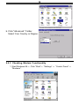
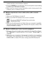
2.2.3 Checking Modem Functionality
1. Start Windows 98 ⇒ Click “Start”⇒ "Settings” ⇒ “Control Panel” ⇒
“Modems”.
15
2. Click “General” and highlight "Motorola SM56 PCI Speakerphone Modem" as shown below.
3. Click "Diagnostic" and highlight the designated COM as shown below.
Click “More Info ...” and the system will communicate with the modem.
16
2.2.4 Uninstall Your Modem
1.Click “Start” ⇒ “Settings” ⇒ “Control Panel” ⇒ “Add/Remove
Programs" .
2.. highlight "Conexant SoftK56 Modem"
3. click "Add/ Remove" and "OK" to remove the modem.
17
Section Three - Installing and Configuring
Communication Software
NOTE: Install the communication software according
to the software user's manual. Be certain that your
software is configured to communicate with the modem
on the same COM port and IRQ line used by the modem.
You may be prompted by the software to configure certain communication parameters. We suggest the following settings:
Baud rate: 57,600 bps
Data bits: 8
Parity: None
Stop bit: 1
Flow Control: RTS/CTS
Initialization string: AT&F
The AT commands used by the modem are compatible with the command
set used by Intel modems. Select a Motorola modem type if prompted by your
data communications software. Select Generic Class 1 or Motorola modem type
when prompted by your Fax or Voice software.
3.1 Using Your Modem
Common modem functions (i.e. dialing, file transfer, faxing) are performed by using communication software in conjunction with the modem.
NOTE: The communication software included with your
modem provides a user friendly interface for all common
modem functions and should be sufficient for all of your
communication needs.
3.2 Where To Go From Here
If you have difficulties getting your modem to work, read Section Four to
find information as well as answers to commonly asked questions and problems
concerning the communication software. Sections Five through Ten contain
reference material (AT commands, S-register, and Result-codes, etc.) and can be
skipped.
NOTE: It is important that you familiarize yourself with
the functions available from the included software by
18
reading its manual (you may also use any other
commercially available communication software).
The software manual includes detailed information
on all common modem functions.
19
Section Four - Troubleshooting Communication
Software
Your modem is designed to provide reliable and trouble-free service. Should
you experience any difficulty, however, the information contained in this section
will assist you in determining and resolving the source of the difficulty. If you
cannot resolve your difficulty after reading this chapter, contact your dealer or
vendor for assistance.
4.1 Modem does not respond to commands.
1. Make sure the modem is not configured with a conflicting COM port and
IRQ setting . If another device in your system is also configured as the
same COM port, it will not work. Similarly, IRQ settings may not overlap.
2. Make sure the communication software is configured with the correct
COM and IRQ settings (same COM port and IRQ line as the modem).
Your communication software will not be able to send-to and receivefrom your modem any data if it does not have the correct COM and IRQ
settings of the modem.
3. Make sure the modem is properly initialized by the communication
software. Your modem may have been improperly initialized by the
software because you have selected an incorrect modem type. Select
"Rockwell" modem type in your data communication software (select
"Generic class 1" and "Rockwell" in your Fax software, respectively).
You may also be prompted to enter an initialization string by the
software. Use AT&F as your initialization string.
4.2 Modem dials, but does not connect.
1. Make sure the COM port setting is identical on both the system AND
the software.
2. Make sure the phone line is working properly. A noisy line will prevent
proper modem operation.
4.3 Modem makes a connection, but no data appears on your
screen.
1. Make sure all communication parameters (baud rate, data, stop, and
parity bits) are properly configured and identical on both sides. Be
certain hardware flow control (RTS/CTS - default) is enabled in both the
20
modem and the communication software.
2. Press the ENTER key several times. The remote system may be waiting
to receive your data before it begins.
3. Make sure the correct terminal emulation mode is being used in the
software (refer to software manual).
4.4 Modem experiences errors while online with a remote
modem.
1. Make sure Call Waiting is turned off.
2. Make sure RTS/CTS hardware flow control is enabled.
Do not use XON/XOFF software flow control when
transferring binary
3. Make sure the data speed is not faster than your computer's capability.
Operating at higher speeds under Windows 95 requires a faster CPU
(Pentium 200MHz or better).
4.5 Modem exhibits poor voice record or playback.
1. Make sure the correct modem type is selected in the Voice/Fax software.
Use "Motorola" or similar selection. Do not select "Cirrus Logic" or
"Lucent".
2. Make sure your computer is fast enough to handle voice operations
(38.4Kbps). Voice operations are CPU intensive and require a Pentium
200MHz MMX or better CPU when running under MS Windows 95.
21
Section Five - AT Command Set
5.1 Executing Commands
Your modem is in Command Mode upon power-on and is ready to receive
and execute “AT” commands. The modem remains in Command Mode until it
makes a connection with a remote modem. Commands may be sent to the modem
from an attached terminal or a PC running a communication program.
This modem is designed to operate at common DTE speeds ranging from
115.2Kbps (or 57.6Kbps) to 300bps. All commands and data must be issued to
the modem using one of the valid DTE speeds.
5.2 Command Format
All commands must begin with the AT prefix, followed by the command
letter and ended with the ENTER key. Spaces are allowed in the command string
to increase command line readability, but are ignored by the modem during
command execution. All commands may be typed in either upper or lower case,
but not mixed. A command issued without any parameters is considered as
specifying the same command with a parameter of “0”.
Example:
ATL[ENTER]
This command causes your modem to lower its speaker volume.
5.3 AT Commands: Basics
ATtention (AT) commands are the means by which you control and monitor
a modem. Typically, the communication applications automatically issues them,
and you need not know the commands and their options.
However, to custom-configure the modem for an application, or to optimiz
performance, you can issue commands through the communucations application yourself. In most communications applications, there is a menu item, or
option, for entering extended or custom AT commands. See your communications application documentation.
You can also configure the modem by issuing AT commands directly from
a simple terminal-emulation application . One such application is HyperTerminal,
which is present on computers that have windows.
To issue an AT command from the terminal-emulation application, you must
ensure that the modem is in command mode (in which it can detect and respond
22
to commands), rather than data mode (in which it is transmitting and receiving
data). To enter command mode from data mode, enter +++. You need not press
the ENTER key.
When entering AT commands, the following basic rules apply:
l
AT commands can be entered in uppercase, lowercase, or mixed text
l
The characters AT begin all AT commands, except A/ and +++
l
The key used as the ENTER key is specified in S-Register S3.
l
The maximum command length is 64 characters.
l You can enter more than one AT command on a line. However, some
commands must occur at the beginning or end of the command line.
5.4 +++ (Plus-Plus-Plus) Command
This command. known as the escape sequence, causes the modem to
stop transmitting data (if it is doing so), and go into command mode.
Issue this command at the computer keyboard, in the communications
application's terminal windows, by typing the plus sign (+) three times.
NOTE: Do not press the ENTER key after the +++
command. It may cancel the command.
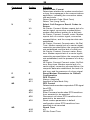
5.5 AT and AT& (Ampersand) Commands
The modem responds to the following AT and AT& command options.
The letters AT (or at) must precede all commands except A/ and +++.
Command
Option
A
A/
(none)
(none)
D
(none)
E
Function
Answer Incoming Call
Repeat Last Command
Re-issues the previous command to the modem.
(Do not press Return; the command executes
as soon as the / is pressed.)
Dial a Number
Instructs the modem to dial the telephone number
that you enter immediately after the ATD
command. Example: ATD5554678. Note; if
multipe ATD commands are used in voice mode,
the modem must be forced to blind-dial after
dial-tone detection.
Echo Async (Keyboard) Input to Terminal
23
Command
Option
E0
E1
H
H0
H1
I
I0
I1
I2
I3
I4
I5
I6
I7
L
M
M0
M1
M2
M3
O
P
Q
T
O0
O1
O2
O3
P
Q0
Q1
T
Function
Detemines whether the characters you type at
the keyboard are displayed (echoed) to the
terminal-emulation window (if it is active) or to
the communiccations applications.
disabled
enabled
Hook
Go on Hook (disconnnect from the telephone
line;hang up)
Go off Hook (connect to the telephone line)
Reguest Information From Modem
"960"
"000"
"OK"
Software Version
"OK"
Disconnect Reason
Country Code
Product Code
Speaker Volume
This parameter is not supported.
Speaker Control
off
On During Training Only
Always on
Off during dialing, on during call progress;off
during data transfer
Return to On-Line Mode
This parameter determines whether the
modem initiates a retrain after changing from
escape mode to data mode, or after a semicolon in dial strings
No retrain
Retrain
Initiate Rate Renegotiation
Rate Renegotiation with silence
Pulse Dial
Result-Code Display
The modem can send result codes and
connect messages to the computer as a
result of connecting or failing to connect;
establishing a data rate; and establishing
error-correction and data-compression
protocols. Refer to : ATV; AT\V ATX
Enable display
Disable display
Tone dial
This command instructs the modem to use
DTMF tone dialing.
24
Command
V
Option
V0
V1
X
X0
X1
X2
X3
X4
Z
Z
&C
&C0
&C1
&D
&D0
&D1
&D2
&D3
&G
&G0
&G1
Function
Result-Code Format
Determines whether the modem sends shortor long- form messages to the communications
application, indicating the connection status,
rate and mode.
Return Numeric Code (Short Form)
Return Text (Long Form)
Select Call-Progress Result Codes to
Return
No Carrier; Connect. Modem reports lack of a
carrier signal; connection success/failure;
modem dials without waiting for a dial tone
No Carrier; Connect; Connect <rate>. Modem
reports lack of a carrier signal; connection
success/failure, and the computer data rate
established
No Carrier; Connect; Connect<rate>; No Dial
Tone. Modem reports lack of a carrier signal;
connection success/failure; the computer data
rate established; and the lack of a dial tone
No Carrier; Connect; Connect <rate>; Busytone. Modem reports lack of a carrier signal;
connection success/failure; the computer data
rate established; and the presence of a busy
signal
No Carrier; Connect; Connect <rate>; No Dialtone; Busy-tone. Modem reports lack of a
carrier signal; connection success/failure; the
computer data rate established; the lack of a
dial tone; and the presence of a busy signal
Reset Modem Parameters to Default
Configuration
DCD Control
Always Asserted
Asserted in Data Mode Only
DTR Control
Determines how modem responds to DTR signal
from DTE.
Ignore DTR
Enter Command mode when DTR transitions
from asserted to de-asserted
Disconnect call when DTR transitions from
asserted to de-asserted
Reset modem parameters to default
configuration when DTR transitions from
asserted-to-de-asserted
Guard Tone
off
550 Hz Guard Tone
25
Command
Option
&G2
&I
&In
&I99
&P
&P0
&P1
&P2
&R
&R0
&R1
&S
&S0
&S1
&T
&T0
&T1
&TD
&TDn
&TD99
&V
&V0
&V1
&V2
Function
1800 Hz Guard Tone
Dial TX Level
Level n, n=0 to15, Default =9
Automatic Level
Pulse Cycle
Used when the modem is instructed to pulse
dial.
40/60 Make/Break Ratio
33/67 Make/Break Ratio
38/62 Make/Break Ratio
CTS Control
Normal
Always On
DSR Control
Always On
On When Modem Recognizes Remote
Test
Terminate Test
Initiate Local Analog Loopback Test
Disconnect the telephone line from the SM56
modem line input connector before using this
command. With SM56 Build 50 or later, set SRegister 46 = 23 (ATS46=23) before executing
&T1.
Dial TX Level
Level n, n=0 to 15
Automatic Level
Modem Status
Short Form Report
Current or Last Connection Report
Long Form Report
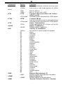
5.6 AT%(Percent) and AT\(Backslash) Commands
The modem responds to the following AT% and AT\ command options
The letters AT (or at) must precede all commands except A/ and +++.
Command
%B
Option
%B0
%B1
%B2
Function
Maximum Modulation Rate
Sets the rate that the modem uses when
connecting in a data modulation mode for
performing functions such as Internet
access or file transfer
Maximum modem rate that the modem supports
300 BPS
1.2 KBPS
26
Command
%C
Option
%B3
%B4
%B6
%B7
%B8
%B9
%B11
%B12
%B13
%B14
%B15
%B16
%B17
%B18
%B19
%B20
%B21
%B22
%B23
%B24
%B25
%B26
%B27
%B28
%B29
%B30
%B31
%B32
%B33
%B34
%B35
%B36
%B37
%B38
%B39
%B40
%B41
%B42
%B43
%B44
%B45
%B46
%B47
%B48
Function
2.4 KBPS
4.8 KBPS
9.6 KBPS
7.2 KBPS
12.0 KBPS
14.4 KBPS
16.8 KBPS
19.2 KBPS
21.6 KBPS
24.0 KBPS
26.4 KBPS
28.8 KBPS
31.2 KBPS
33.6 KBPS
32.0 KBPS
34.0 KBPS
36.0 KBPS
38.0 KBPS
40.0 KBPS
42.0 KBPS
44.0 KBPS
46.0 KBPS
48.0 KBPS
50.0 KBPS
52.0 KBPS
54.0 KBPS
56.0 KBPS
58.0 KBPS
60.0 KBPS
28000 BPS
29333 BPS
30666 BPS
33333 BPS
34666 BPS
37333 BPS
38666 BPS
41333 BPS
42666 BPS
45333 BPS
46666 BPS
49333 BPS
50666 BPS
53333 BPS
54666 BPS
Data Compression
Determines whether the modem implements
methods of Increasing the effective data rate
by reducing the
27
Command
Option
%C0
%C1
%D
%D0
%Dn
%L
%L0
%L1
%L2
%L3
%L4
%L7
%L6
%L8
%L9
%L11
%L12
%L13
%L14
%L15
%L16
%L17
%L18
%L19
%L20
%L21
%L22
%L23
%L24
%L25
%L26
%L27
%L28
%L29
%L30
%L31
%L32
%L33
%L34
%L35
%L36
%L37
%L38
%L39
%L40
Function
number of bits used to represent data.
Disable Compression
Enable Compression
Disconnect Buffer Delay
Controls the delay after detection of a disconnect
request before the modem disconnects from
the telephone line
Disable Delay
Delay for n Seconds (n = 1 to 255)
Minimum Modulation Rate
Minimum modem rate that the modem supports
300 BPS
1.2 KBPS
2.4 KBPS
4.8 KBPS
7.2 KBPS
9.6 KBPS
12.0 KBPS
14.4 KBPS
16.8 KBPS
19.2 KBPS
21.6 KBPS
24.0 KBPS
26.4 KBPS
28.8 KBPS
31.2 KBPS
33.6 KBPS
32.0 KBPS
34.0 KBPS
36.0 KBPS
38.0 KBPS
40.0 KBPS
42.0 KBPS
44.0 KBPS
46.0 KBPS
48.0 KBPS
50.0 KBPS
52.0 KBPS
54.0 KBPS
56.0 KBPS
58.0 KBPS
60.0 KBPS
28000 BPS
29333 BPS
30666 BPS
33333 BPS
34666 BPS
37333 BPS
38666 BPS
28
Command
Option
%L41
%L42
%L43
%L44
%L45
%L46
%L47
%L48
\K
\K1
\K3
\K5
\N
\N0
\N1
\N4
\N6
\N7
\Q
\Q0
\Q1
\Q3
\T
\T0
\Tn
\V
Function
41333 BPS
42666 BPS
60.0 KBPS
46666 BPS
49333 BPS
50666 BPS
53333 BPS
54666 BPS
Break Handling Method
Destructive Expedited
Non-destructive Expedited
Non-destructive Non-expedited
Error-Correction Mode
Normal
Direct
LAP-M Only
Reliable
Auto-Reliable
DTE Flow control
Disable
XON/XOFF (software flow control)
RTS CTS (hardware flow control)
Disconnect on DTE Inactivity
Disable
Disconnect after n minutes of inactivity by the
computer; n=0 to 255
Connect Message Format
Determines which message the modem
generates at connection time
/V0
Display DTE Rate
/V1
DTE with EC/DC Message
/V2
Display DCE Rate
/V3
DCE with EC/DC Message
/V4
DCE with Modulation & EC/DC Message
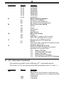
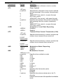
5.7 AT* (Asterisk) Commands
The modem responds to the following AT” command options.
The letters AT (or at) must precede all commands expect A/ and +++.
Command
*DD
Option
*DD0
*DD1
Function
Dial wait
Specifies the time interval to wait when the
modem encounters a W or w while processing
a dial string
2 Seconds
3 Seconds
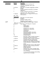
29
Command
Option
*DD2
*DD3
*DD4
*DD5
*DD6
*DD7
*DD8
*LS
*LS0
*LS1
*LS2
*MM
*MM0
*MM1
*MM2
*MM4
*MM5
*MM6
*MM10
*MM11
*MM12
*MM13
*MM14
*MM15
*MM16
Function
4 Seconds
6 Seconds
12 Seconds
15 Seconds
20 Seconds
30 Seconds
40 Seconds
Low-Speed Operation Protocol
Lets you select a communications protocol to
communicate with very low-speed or older
modems.
Bell 103
ITU-T V.21 (international standard)
Bell 103 or ITU-T V.21 (Auto determination)
Modulation Mode
V.34 Auto Modulation
V.21
Bell 103
V.22/Bell 212
V.22bis
V.23
V.32 Only
V.32 bis
V.34 Only
K56flex™ Only
K56flex™ Auto-modulation
V.90 Only
V.90 Auto
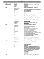
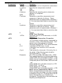
5.8 AT + (Plus) Commands
The modem responds to the following AT+ command options.
The letters AT (or at) must precede all commands expect A/ and +++.
AT commands that begin with :
l +D control data compression
l +F control fax application operation
l +V control voice application operation
These commands are primarily used by software applications
Command Option
+A8E
+A8= a,b,c,d
a options:
0
1
Function
V.8 Configuration
Specifies V.8 origination negotiation options
Disable
Enable computer-controlled V.8 orgination
negotiation
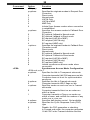
30
Command
Option
6
b options:
0
1
5
C options:
00h – FFh,
default=00h
d options:
0
1
2
+A8T
Function
Enable computer-controlled V.8
orgination negotiation with +A8x
indications
Specifies V.8 answer negotiation options
Disable
Enable computer-controlled V.8 answer
negotiation
Enable computer-controlled V.8 answer
negotiation with +A8x indications
Specifies the V.8 CI Signal Call Function
Octet options
Specifies V.8 control options
Disabled
Enabled, modem control
Enabled, computer control
V.8bis Signal and Message Control
+A8T=a,b,c,d,e,f
Specifies V.8 bis Signal to Transmit
a options:
0
None
1
Initiating MRe
2
Initiating MRd
3
Initiating Cre, low power
4
Initiating Cre, high power
5
Initiating Crd
6
Initiating Esi
7
Responding MRd, low power
8
Responding MRd, high power
9
Responding CRd
10
Responding ESr
b options:
Specifies V.8bis Transmit message 1
hexadecimal octet coded string
c options:
Specifies V.8bis Transmit message 2
hexadecimal octet coded string
d options:
Specifies V.8bis signal detection
0
Enable detection of initiating V.8bis signal
1
Enable detection of responding V.8bis
signal
2
Enable detection of both V.8bis signals
e options:
Specifies V.8bis message detection
0
Disable detection
1
Enable detection
f options:
Specifies the V.8bis message delay
0
No delay between transmitting signal
and messages
1
1.5 second delay between transmitting
signal and any messages
31
Command
+DR
Option
+DR=0
+DR=1
+DS
+DS=p,q,r,s
p options:
0
1
2
3
q options:
0
1
r options:
512-65535
s options:
6-250
+EB
+EB=p,q,r
p options:
0
1
2
3
q options:
0
1
r options:
0
1 – 254,
default=100
+ER
Specifies compression on/off direction
No compression
Tx direction only
Rx direction only
Both directions; accept any direction
Specifies negotiation
Do not disconnect if V.42bis is not
negotiated per Direction option
Disconnect if V.42bis is not negotiated
per Direction option
Specifies maximum dictionary size
Default=2048
Specifies maximum string size
Default = 32
Break Handling Control
Specifies break selection
Ignore break
Non-expedited, non-destructive
Expedited, non-destructive
Expedited, destructive
Specifies break length control
Transmission of V.42 L-SIGNAL does
not indicate break length
Transmission of V.42 L-SIGNAL
indicates break length
Specifies the default break-length
Break is not transmitted to the computer
Break length, in 0.01-second increments
Error-Control Reporting
+ER=a
a options:
0
1
+ES
Function
Data Compression Reporting
Disabled
Enabled
Data Compression Control
Specifies the modem’s error-cotrol
reporting activity
Disabled
Enabled : modem issues one of the
following messages to the computer,
before it issues a connect message.
The specifies the Error Correction
protocol negotiated:
+ER:NONE
+ER:LAPM
+ER:ALT
Error-Correction (EC) Control
32
Command
+ ESA
Option
+ES=p,q,r
p options:
Function
Specifies the originate-modem’s Request Error
Correction
0
Direct mode
1
Normal mode
2
LAP-M Only
3
LAP-M or MNP
4
MNP Only
6
Initiate Sync Access modem when connection
is established
q options:
Specifies the answer-modem’s Fallback Error
Correction
0
EC optional, fallback to Normal mode
1
EC optional, fallback to Direct mode
2
EC required (LAP-M or MNP)
3
EC required (LAP-M only)
4
EC required (MNP only)
r options:
Specifies the originate-modem’s Fallback Error
Correction mode
0
Direct mode
1
Normal mode
2
EC optional, fallback to Normal mode
3
EC optional. Fallback to Direct mode
4
EC required (LAP-M or MNP)
5
EC required (LAP-M only)
6
EC required (MNP only)
8
Initiate synchronous access mode when
connected
Synchronous Access Mode Configuration
+ESA=a,b,c,d,e,f
a options:
Specifies the Idle in Transparent sub-mode
0
Computer transmits 8 bit SYN sequence on idle.
Computer does not hunt for synchronization
sequence
b options:
Specifies the Idle in Framed sub-mode
0
Computer transmits HDLC flags on idle
c options:
Specifies under-run and over-run in Framed
sub-mode
0
Computer transmits Abort on an under-run
within a frame
1
Computer transmits a Flag on an under-run
within a frame, and notifies the modem of any
under-run or over-run
d options:
Specifies half-duplex control. Not available
e options:
Specifies the Cyclic Response Code (CRC)
type
0
Disable. No CRC generation or checking.
1
In Framed sub-mode, the computer generates
16-bit CRC in the Transmit direction and the
33
Command
Option
f options:
0
+ETBM
+ETBM-p,q,r
p options:
+FCLASS
+FLO
+FMI?
+FMM?
+FMR?
+FRH
+FRM
Function
modem generates 16-bit CRC on the Reeive
direction
Specifies Non-Return to Zero (NRZI) options
NRZI encoding and decoding are disabled.
Disconnect Buffer Delay Control
Specifies the disconnect buffer delay with
pending transmit data
0
Discard buffered data and disconnect
1
Attempt to transmit until all data is delivered, then
disconnect Ignore timer.
2
Attempt to transmit until all data is delivered or
timer expires.
q options:
Specifies the disconnect buffer delay with
pending receive data
0
Discard buffered data and disconnect
1
Attempt to transmit until all data is delivereed,
then disconnect. Ignore timer.
2
Attempt to transmit until all data is delivered or
timer expires.
r options:
Disconnect buffer delay timer, in 1-second
increments
1 – 255, default=0
Fax/Modem Mode
+FCLASS=0
Modem Mode
+FCLASS=1
Fax Class 1
Fax Flow Control
+FLO=0
None
+FLO=1
XON/XOFF
+FLO=2
RTS/CTS
Report Manufacturer ID
Report Modem ID
Report Revision Level
Receive High-Level Data Link Control
(HDLC)M ode
Sets mode and transmit/receive rate for faxes
+FRH=3
V.21 at 300 BPS
+FRH=24
V.27ter at 2.4 KBPS
+FRH=48
V.27ter at 4.8 KBPS
+FRH=72
V.27ter at 7.2 KBPS
+FRH=73
V.27ter at 7.2 KBPS with long train time
+FRH=74
V.27ter at 7.2 KBPS with short train time
+FRH=96
V.29 at 9.6 KBPS
+FRH=97
V.17 at 9.6 KBPS with long train time
+FRH=98
V.17 at 9.6 KBPS with short train time
+FRH=121
V.17 at 12.0 KBPS with long train time
+FRH=122
V.17 at 12.0 KBPS with short train time
+FRH=145
V.17 at 14.4 KBPS with long train time
+FRH=146
V.17 at 14.4 KBPS with short train time
Receive Mode
34
Command
Option
`
+FRMm
Function
Sets the modulation mode for receiving axes
Use mode m; see mode options for +FRH,
+FTH
+FRS
+FRSn
+ FTH
+FTM
+FTH mode
+FTM
Wait for Silence
Wait (n*10) ms; n=0 to 255
Transmit High-Level Data Link Control
(HDLC) mode
Use Mode mode; see options for +FRH, above.
Transmit Mode
Sets the modulation mode for transmitting faxes
Use mode mode; see options for +FRH, above.
Pause Transmission
Pause transmission for (n*10)ms; n=0 to 255
Report Capabilities
Display modem Capabilities
Country of Installation
Set country in which modem is installed
Japan
Germany
Australia
Austria
Belgium
Brazil
Canada
Czech Republic
Denmark
Finland
France
Germany
Hong Kong
Ireland
Israel
Italy
Malaysia
Netherlands
Norway
Portugal
Singapore
South Africa
Spain
Sweden
Switzerland
Thailand
Turkey
United Kingdom
USA
Request Manufacturer ID
Display modem-manufacturer information
Request Model ID
Display modem-model information
Request Software Revision Number
above
+FTM mode
+FTS
+FTSn
+GCAP
+GCAP
+GCI
+GCI=a
00
04
09
0A
0F
16
20
2E
31
3C
3D
42
50
57
58
59
6C
7B
82
8B
8C
9F
A0
A5
A6
A9
AE
B4
B5
+GMI
+GMI?
+GMM
+GMM?
+GMR
35
Command
Option
+GMR?
+IFC
+IFC=p,q
p options:
0
1
2
3
q options:
0
1
2
+ILRR
+ILRR=0
+ILRR=1
+ITF
+ITF=a,b
a options:
0-2047
default=255
b options:
Function
Display modem-software revision number
Flow Control
Specifies the computer’s flow control method
for data passing to the modem (downstream)
None
XON/XOFF flow control, no pass-through
RTS flow control
XON/XOFF flow control, with pass-through
Specifies the modem’s flow control method for
data passing from the modem (upstream)
None
XON/XOFF flow control, no pass-through
CTS flow control
Computer’s Local Rate Reporting
Disabled
Enabled
Transmit Flow Control Thresholds (V.80)
Specifies the threshold, in octests, at which the
modem turns transmit flow-control off
Specifies the threshold, in octests, at which the
modem turns transmit flow-control on
0-2047
default =255
+MR
+MR=0
+MR-1
+MS
Modulation Mode Reporting
Disabled
Enabled
Modulation Control
+MS=p,q,r,s,t,u
p options:
Specifies the modulation mode
V21
V.21
V22
V.22
V22B
V.22bis
V23C
V.23c
V32
V.32
V32B
V.32bis
V34
V.34
K56FLEX
K56flex™
V90
V.90
q options:
Specifies the Automode option
0
Disabled
1
Enabled
r options:
Specifies the minimum data rate in the Tx
direction
0
Use the minimum rate of the specified modulation
mode
36
Command
Option
300 – 60000
s options:
0
300 – 60000
t options:
0
300 – 60000
u options:
0
300 – 60000
+VCID
+VCID=0
+VCID=1
+VCID=?
+VDR
+VDR=m,n
m options:
0
1
n options:
0
1-255
+VEM
0
1-255
+VGT
1-255
+VIP
+VLS
0
1
8
9
Function
BPS
Specifies the maximun data rate in the Tx
direction
Use the maximum rate of the specified
modulation mode
BPS
Specifies the minimun data rate in the Rx
direction
Use the minimum rate of the specified modulation
mode
BPS
Specifies the maximum data rate in the Rx
direction
Use the maximum rate of the specified
modulation mode
BPS
Caller ID Control
This option takes effect only where the function
is supported.
Disable
Enable
Display Caller ID Status (returns 0 or 1)
Distinctive Ring Control and Report
This option takes effect only where the function
is supported
Note: If Distinctive Ring is enabled, the first
ring reported by the modem may be incorrect.
Specifies control
Disable
Enable
Specifies reporting
Produce DROFF/DRON report, no RING
Produce DROFF/DRON, followed by RING after
delay of n/10 seconds
Event Rporting and Masking Control
Bit-mapped even control mask. See Event
Reporting Word
Automatic Gain Control
Relative range, where 128 indicates a nominal
value.
Transmit Volume
Relative range, where 128 indicates a normal
value.
Initialize Volume Parameters
Set voice parameters to factory-default options
Select Analog Source and Destination
DCE(modem) on-hook
DCE off-hook, DCE connected to telco
DCE on-hook, DCE connected to speaker
speakerphone with mute enabled
37
Command
+VNH
+VPR
+VRA
+VRN
+VRX
+VSD
+VSM
Option
11
13
Function
DCE on-hook, DCE connected to microphone
DCE off-hook, DCE conneted to telco, speaker,
and microphone (speakerphone)
Automatic Hang-up Control
+VNH=0
Retain automatic hang-ups
+VNH=1
Disable DCE-initiated automatic hang-ups
+VNH=2
Disable all Automatic hang-ups
Voice DTE-DCE Rate
+VPR=0
Autobaud
Ringback Gone Timer
If, after detecting ringback, no further ringbacks
are detected after n/10 seconds, operate as
if the remote device answered the call.
+VRA=n
If no ringback is received, after n/10 seconds,
assume that the remote device has answered
the call; n=0-255
Ringback Never Occurred
+VRN=n
After n/10 seconds, operate as if ringback has
never occurred; n = 0-255
Voice Receive Mode
Determines whether the modem generates a
periodic beep, audible to both parties on the
speakerphone, indicating that the call is being
recorded.
Notes: the speakerphone state does not have
to be reset after recording to the line or playing
a message to the line. The baud rate is not set
before the StartPlay and StartRecord
commands. The baud rate is not reset after the
StopPlay and Stoprecord. Commands.
+VRX or VRX=0
Produce Periodic DCE Tone While Recording
+VRX=1
Disable Periodic DCE Tone Production
During Recording
Remote Silence-Detection Properties
+VSD=m,n
Used in answering-machine mode.
Specifies the volume and duration
thresholds that determine whether the
remote device has hung up.
m options:
Specifies the silence-detection level
0
Used current + VSM value; or, if current +VSM
value is 0, use 128.
127
Low Threshold (most sensitive)
128
Medium Threshold
129
High Threshold (least sensitive)
n options:
Specifies the silence-detection duration
0
Disable
1-255
Detect n/10 seconds silence; n = 0-255
60
Default=6 seconds
Speech Compression Properties
38
Command
Option
+VSM=m,n,p,q
m options:
128
129
n options:
8000
P options:
0
q options:
0
+VTD
+VTDn
+VTS
D
(f,n)
(f,g,n)
Examples:
+VTX
Function
Specifies the voice compression parameters
Specifies the compression method
PCM
ADPCM
Specifies the sampling rate to determine
whether to compress
8000 Hz
Parameter p specifies compression and
expansion of periods of silence. These
parameters are not implemented in Release 1.
0. You may leave them blank or enter the value
0.
Disable
Parameter q specifies compression and
expansion of periods of silence. These
parameters are not implemented in Release 1.
0. You may leave them blank or enter the value
0.
Disable
DTMF Tone Duration
Generate tone for n/100 seconds; n =0-255.
Default=100.
DTMF Tone Generation Properties
+VTS accepts multiple options, separated by
commas, of any of the following types. Use
square and curly brackets as shown.
Generate default DTMF Tone, default duration
t specifies a DTMF tone; t = 0-9
n specifies tone duration n/100 seconds;
n = 1-500
f and g specify a tone pair, f Hz and g Hz; in
the range n Specifies tone-pair duration
n/100 seconds; n = 1-500
AT+VTS=4,{},[1000,1300,50],8.{*5},[,,100]5
This example specifies the following sequence:
1.Play DTMF 4 for the duration stored in + VTD
2.Play silence for the duration stored in +VTD
3.Play tone pair at 1000 Hz and 1300 Hz for 500
ms
4.Play DTMF 8 for a duration stored in +VTD
5.Play DTMF * for 50 ms
6.Play silence for 1 second
7.Play DTMF 5 for the duration stored in + VTD
Enter Voive-Transmission Mode
Notes: the speakerphone state does not have
to be reset after recording to the line or playing
a message to the line. The baud rate is not set
before the StartPlay and StartRecord
commands. The baud rate is not reset after the
StopPlay and StopRecord.
39
Section Six - S Register Summary
Your modem has 16 registers, designated S0 through S89. Table 6-1 shows
the registers, their functions, and their default values. Some registers can have
their values changed by commands. If you use a command to change a register
value, the command remains in effect until you turn off or reset your modem.
Your modem then reverts to the operating characteristics specified in its
nonvolatile memory. Refer to Section Five for information on how to use the
AT commands to manipulate the S registers.
NOTE: The default value and range of some S-registers
listed below could vary with country.
Table 6-1 S - Registers
Register
Function
Range/units
Default
S0
Auto-answer or Ring Number
0-255 /rings
0
S1
Ring count
0-255 /rings
0
S2
Select Escape character
0-255 /ASCII
43
S3
SelectCarriage-return character
0-127 /ASCII
13
S4
Select Line-feed character
0-127 /ASCII
10
S5
Select Backspace character
0-127 /ASCII
8
S6
Blind Dial
0-255 /seconds
2
S7
Call Time-out
0-255 /seconds
60
S8
Pause Delay
0-255 /seconds
2
S10
DCD Loss Disconnect
0-255/0.1 second
S11
Tone Length
60-255 /milliseconds
72
S12
Escape Code Guard time
0-255 /0.02 second
50
S18
Test Timer
0-255 /second
NOTE: Read bits from right to left..
Bit
Signal
Bit
Signal
14
0
40
Section Seven - Event Reporting Word
Your can use the AT+VEM command to define events on which to report.
The list is encoded as a word composed of the following bits.
A 1 in a bit- position indicates an enent is reported.
A 0 in a bit- position indicates an enent is not reported.
NOTE: Read bits from right to left..
Bit
0
Signal
Caller ID (effective only where
function is supported)
Bit
Signal
2
Distinctive Ring (effective only
where function is supported)
3
RING
4
DTMFDetection
5
Receive Buffer Overrun
6
Fax Calling
9
PresumedHang-Up(SILENCE)
Time-Out
10
Presumed End-of-Message (QUIET)
Time-Out
19
BUSY
20
DIALTONE
23
Playback Buffer Underrun
25
Fax or Data Answering Modem
Detected
27
Voice Detected