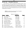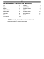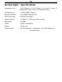
1
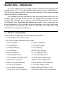
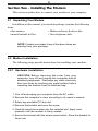
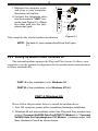
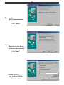
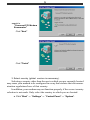
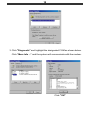
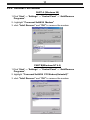
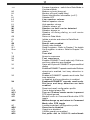
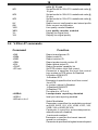
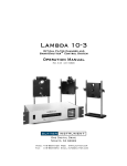
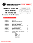
HSF
FAX / MODEM
SoftSoft
USER'S GUIDE
Ver 1.0
CTR-21 Compliance Statement
The equipment has been approved in accordance with Council Decision 98/482/EC for pan- European single
terminal connection to the public switched telephone network (PSTN). However, due to differences between
the individual PSTNs provided in different countries, the approval dose not, of itself, give an unconditional
assurance of successful operation on every PSTN network termination point.
In the event of problems, you should contact your equipment supplier in the first instace.
F
The manufacturer should ensure that the vendor and user of the equipment is clearly informed
of the above information by means of packaging and /or user manuals or other forms of user
instructions.
The information in this document is subject to change without notice and does not represent a commitment on the
part of the vendor.
No warranty of representation, either expressed or implied, is made with respect to the quality, accuracy or fitness
for any particular purpose of this document. The manufacturer reserves the right to make changes to the content
of this document and/or the products associated with it at any time without obligation to notify any person or
organisation of such changes.
In no event will the manufacturer be liable for direct, indirect, special, incidental or consequential damages arising
out of the use or inability to use this product or documentation, even if advised of the possibility of such damages.
Microsoft Windows is a trademark of Microsoft Corporation.
All product names are trademarks or registered trademarks of their respective owners.
FCC Compliance Statement
This device complies with Part 15 and 68 of the FCC Rules. Operation is subject to the following two conditions:
1. this device may not cause harmful interference, and
2. this device must accept any interference received, including interference that may cause undesired
operation.
FCC Warning Statement
This equipment has been tested and found to comply with the limits for a Class B digital device, pursuant to Part
15 and 68 of the FCC Rules. These limits are designed to provide reasonable protection against harmful interference
in a residential installation. This equipment generates, uses and can emit radio frequency energy and, if not installed
or used in accordance with the instructions, may cause interference to radio communications. However, television
reception interference can be determined by turning the equipment off and on, the user is encouraged to correct
the interference by one or more of the following measures:
•
•
•
•
Reorient or relocate the receiving antenna
Increase the separation between the equipment and the receiver
Connect the equipment into an outlet different from that to which the receiver is connected
Consult the dealer or an experienced radio/TV technician for help.
F
Changes or modifications not expressly approved by the party responsible for compliance could
void the user’s authority to operate the equipment
The information contained in this manual has been verified at the time of this
manual's printing. The manufacturer reserves the right to make any change and
improvement in the product described in this manual at any time and without
notice.
All registered trademarks are the property of their respective owners.Copyright
©1999 All rights reserved. No reproduction of this document in any form is
permitted without prior written authorization from the manufacturer.
Version 1.0
Table of Contents
Section One - Introduction
1
1.1 Modem Compatibility ......................................................... 1
Section Two - Installing The Modem
2
2.1 Unpacking Your Modem ..................................................... 2
2.2 Modem Installation ............................................................. 2
2.2.1 Hardware Installation .............................................. 2
2.2.2 Setting Up Modem Under Windows 98 .................. 3
2.2.3 Checking Modem Functionality .............................. 9
2.2.4 Uninstall Your Modem .......................................... 11
Section Three - Installing and Configuring
Communication Software
12
3.1 Using Your Modem ........................................................... 12
3.2 Where To Go From Here .................................................. 12
Section Four - Troubleshooting Communication
Software
14
4.1 Modem does not respond to commands. .......................... 14
4.2 Modem dials, but does not connect. ................................. 14
4.3 Modem makes a connection, but no data appears on your
screen. ............................................................................... 14
4.4 Modem experiences errors while online with a remote
modem. ............................................................................. 15
4.5 Modem exhibits poor voice record or playback. .............. 15
Section Five - AT Command Set
16
5.1 Executing Commands ....................................................... 16
5.2 Command Format ............................................................. 16
5.3 AT Commands .................................................................. 16
5.4 V.25ter AT commands ...................................................... 18
Section Six - S Register Summary
20
Section Seven - Result Code Summary
21
Section Eight - Specifications
22
1
Section One - Introduction
Your new 56Kbps modem is a high speed PC communication peripheral that
combines Data, Fax, Voice and Speakerphone functions into a single device.
This high performance modem connects your computer to all popular modems
and fax machines available today.
This manual provides installation and operating instructions for your
modem. Also included in this manual are listings and descriptions of the
standard AT command set, S-registers, and troubleshooting tips. Be certain to
read Section Two - Installing the Modem thoroughly before performing the
actual installation. Our customer support experience has shown that many
costly and time-consuming calls can be avoided with closer attention to the
installation information provided here.
1.1 Modem Compatibility
Your modem is compatible with the following standards:
• V.90 (56Kbps down stream only)
• K56 flex (56kbps download stream only)
• V.34 (33600 bps)
• V.32bis (14400 bps)
• V.32 (9600 bps)
• V.23 (1200/75 bps)
• V.22bis (2400 bps)
• V.22 (1200 bps)
• V.21 (300 bps)
• Bell 212A (1200 bps)
• Bell 103 (300 bps)
• V.17 (14400 bps FAX)
• V.29 (9600 bps FAX)
• V.27ter (4800 bps FAX)
• V.21 Channel-2 (300 bps FAX)
• V.42bis (data compression)
• V.42 (error correction)
• MNP 5 (data compression)
• MNP 2-4 (error correction)
• TIA/EIA 602 AT Command set
• V.8 Start-up sequence
• V.80(Video Ready mode)
• V.8 bis Start-up sequence
• Plug and Play PCI Spec. V1.0a
• TIA/EIA 695 Voice command
• TIA/EIA578 Class 1 Fax Command Set
2
Section Two - Installing The Modem
This section explains how to connect your modem to your computer.
2.1 Unpacking Your Modem
In addition to this manual, your modem package contains the following
items:
• One modem
• Modem software & driver disc
• manual include in Disc
• One telephone cable
NOTE: Contact your dealer if any of the above items are
missing from your package.
2.2 Modem Installation
The following steps provide instructions for installing your modem.
2.2.1 Hardware Installation
CAUTION: Before removing the cover from your
computer, turn off and unplug the computer and all
attached peripherals. Discharge any static electricity
from your body by touching any metal surface before
removing the modem from its antistatic bag.
1. Turn off and unplug your computer from the AC outlet.
2. Remove the computer's cover according to its owner's manual.
3. Select any available PCI bus slot.
4. Remove the bracket and save the screw.
5. Carefully insert the modem into the selected slot. Apply even
pressure until the modem is firmly seated.
6. Secure the bracket with the screw saved earlier. Store the bracket for
future use.
3
7. Replace the computer cover
and plug in your computer.
Reconnect all cables.
1
2
4
3
5
7
*
6
8
0
9
8. Connect the telephone able
into the modem's "LINE" connector (see Figure 2-1). Attach
the other end into the telephone wall jack.
This completes the internal modem installation.
Figure 2-1
NOTE: The back of your modem should look like Figure
2-1.
2.2.2 Setting Up Modem Under Windows 98
This internal modem supports the Plug and Play feature. It allows your
computer to set the optimal configuration for the modem and communication
software automatically.
PART A of the installation is for Windows 98.
PART B of the installation is for Windows NT 4.0 .
PART A (Windows 98)
Please follow the procedure below to install the modem driver:
1. Turn ON computer power after completing hardware installation.
2. Windows 98 will automatically detect the Plug and Play modem and
setup a "Conexant SoftK56 Data Fax RTAD PCI Modem" or "Conexant
SoftK56 Data Fax Speakerphone PCI Modem" message under Add
New Hardware Found as shown below.
4
Auto detect
"PCI Communication
Device"
Click " Next"
select
"Search for the best
driver for your device"
Click "Next"
Direct to CD-ROM
(ex. F:\Drivers\W98)
Click "Next"
5
search to
"Conexant PCI Modem
Enumerator"
Click "Next"
Click "Finish"
3. Select country (global version is necessary).
Selecting a country other than the one in which you are currently located
may cause your modem to be configured in a way that violates the telecommunication regulations/laws of that country.
In addition, your modem may not function properly if the correct country
selection is not made. Only select the country in which you are located.
a. Click “Start” ⇒ “Settings” ⇒ “Control Panel” ⇒ “System".
6
b. Click "Country Select" Folder . Select Your Country or Region.
PART B (Windows NT 4.0)
Please follow the procedure below to install the modem driver:
1. Please click "Start " ⇒ "Run"
2. choose E:\Drivers\NT40\Setup.exe (E=CD-ROM driver letter) after
put the installation CD-ROM into your drive.
7
Run
"E:\Drivers\NT40\Setup.exe
Click "OK"
Click "Next"
Search to
"Conexant SoftK56
Data Fax RTAD PCI
Modem"
Click "Next"
8
Click "Finish"
3. Select country (global version is necessary).
Selecting a country other than the one in which you are currently
located may cause your modem to be configured in a way that
violates the telecommunication regulations/laws of that country.
In addition, your modem may not function properly if the correct
country selection is not made. Only select the country in which you are
located.
a. Click “Start” ⇒ “Settings” ⇒ “Control Panel” ⇒ “HSF Modem
Country Select".
b. Select Your Country or Region.
9
2.2.3 Checking Modem Functionality
1. Start Windows 98 ⇒ Click “Start”⇒ "Settings” ⇒ “Control Panel” ⇒
“Modem”.
2. Click “General” and highlight "Conexant SoftK56 Data Fax RTAD
PCI Modem" as shown below.
10
3. Click "Diagnostic" and highlight the designated COM as shown below.
Click “More Info ...” and the system will communicate with the modem.
Click "OK"
11
2.2.4 Uninstall Your Modem
PART A (Windows 98)
1.Click “Start” ⇒ “Settings” ⇒ “Control Panel” ⇒ “Add/Remove
Programs" .
2.. highlight "Conexant SoftK56 Modem"
3. click "Add/ Remove" and "OK" to remove the modem.
PART B(Windows NT 4.0)
1.Click “Start” ⇒ “Settings” ⇒ “Control Panel” ⇒ “Add/Remove
Programs" .
2. highlight "Conexant SoftK56 PCI Modem(Uninstall)"
3. click "Add/ Remove" and "OK" to remove the modem.
12
Section Three - Installing and Configuring
Communication Software
NOTE: Install the communication software according
to the software user's manual. Be certain that your
software is configured to communicate with the modem
on the same COM port and IRQ line used by the modem.
You may be prompted by the software to configure certain communication parameters. We suggest the following settings:
Baud rate: 57,600 bps
Data bits: 8
Parity: None
Stop bit: 1
Flow Control: RTS/CTS
Initialization string: AT&F
The AT commands used by the modem are compatible with the command
set used by Intel modems. Select a Rockwell modem type if prompted by your
data communications software. Select Generic Class 1 or Rockwell modem type
when prompted by your Fax or Voice software.
3.1 Using Your Modem
Common modem functions (i.e. dialing, file transfer, faxing) are performed by using communication software in conjunction with the modem.
NOTE: The communication software included with your
modem provides a user friendly interface for all common
modem functions and should be sufficient for all of your
communication needs.
3.2 Where To Go From Here
If you have difficulties getting your modem to work, read Section Four to
find information as well as answers to commonly asked questions and problems
concerning the communication software. Sections Five through Ten contain
reference material (AT commands, S-register, and Result-codes, etc.) and can be
skipped.
NOTE: It is important that you familiarize yourself with
the functions available from the included software by
13
reading its manual (you may also use any other
commercially available communication software). The
software manual includes detailed information on all
common modem functions.
14
Section Four - Troubleshooting Communication
Software
Your modem is designed to provide reliable and trouble-free service. Should
you experience any difficulty, however, the information contained in this section
will assist you in determining and resolving the source of the difficulty. If you
cannot resolve your difficulty after reading this chapter, contact your dealer or
vendor for assistance.
4.1 Modem does not respond to commands.
1. Make sure the modem is not configured with a conflicting COM port and
IRQ setting . If another device in your system is also configured as the
same COM port, it will not work. Similarly, IRQ settings may not overlap.
2. Make sure the communication software is configured with the correct
COM and IRQ settings (same COM port and IRQ line as the modem).
Your communication software will not be able to send-to and receivefrom your modem any data if it does not have the correct COM and IRQ
settings of the modem.
3. Make sure the modem is properly initialized by the communication
software. Your modem may have been improperly initialized by the
software because you have selected an incorrect modem type. Select
"Rockwell" modem type in your data communication software (select
"Generic class 1" and "Rockwell" in your Fax software, respectively).
You may also be prompted to enter an initialization string by the
software. Use AT&F as your initialization string.
4.2 Modem dials, but does not connect.
1. Make sure the COM port setting is identical on both the system AND
the software.
2. Make sure the phone line is working properly. A noisy line will prevent
proper modem operation.
4.3 Modem makes a connection, but no data appears on your
screen.
1. Make sure all communication parameters (baud rate, data, stop, and
parity bits) are properly configured and identical on both sides. Be
certain hardware flow control (RTS/CTS - default) is enabled in both the
15
modem and the communication software.
2. Press the ENTER key several times. The remote system may be waiting
to receive your data before it begins.
3. Make sure the correct terminal emulation mode is being used in the
software (refer to software manual).
4.4 Modem experiences errors while online with a remote
modem.
1. Make sure Call Waiting is turned off.
2. Make sure RTS/CTS hardware flow control is enabled.
Do not use XON/XOFF software flow control when
transferring binary
3. Make sure the data speed is not faster than your computer's capability.
Operating at higher speeds under Windows 95 requires a faster CPU
(Pentium 200MHz or better).
4.5 Modem exhibits poor voice record or playback.
1. Make sure the correct modem type is selected in the Voice/Fax software.
Use "Rockwell" or similar selection. Do not select "Cirrus Logic" or
"Lucent".
2. Make sure your computer is fast enough to handle voice operations
(38.4Kbps). Voice operations are CPU intensive and require a Pentium
200MHz or better CPU when running under MS Windows 95.
16
Section Five - AT Command Set
5.1 Executing Commands
Your modem is in Command Mode upon power-on and is ready to receive
and execute “AT” commands. The modem remains in Command Mode until it
makes a connection with a remote modem. Commands may be sent to the modem
from an attached terminal or a PC running a communication program.
This modem is designed to operate at common DTE speeds ranging from
115.2Kbps (or 57.6Kbps) to 300bps. All commands and data must be issued to
the modem using one of the valid DTE speeds.
5.2 Command Format
All commands must begin with the AT prefix, followed by the command
letter and ended with the ENTER key. Spaces are allowed in the command string
to increase command line readability, but are ignored by the modem during
command execution. All commands may be typed in either upper or lower case,
but not mixed. A command issued without any parameters is considered as
specifying the same command with a parameter of “0”.
Example:
ATL[ENTER]
This command causes your modem to lower its speaker volume.
5.3 AT Commands
All default settings are printed in bold text.
Command
Function
A
A/
Dn
Answer incoming call
Repeat Last command. Do not preceed A/ with
0 - 9, A-D, # and *
L
Redial last number
P
Pulse dial
T
Tone dial
W
Wait fo second dial tone
,
Pause
@
wait for 5 seconds of silence
!
flash
;
return to command mode after dialing
&
wait for AT&T bong tone
Command echo disabled
Command echo enabled
E0
E1
17
+++
H0
H1
In
L0
L1
L2
L3
M0
M1
M2
M3
O0
O1
P
Q0
Q1
Sr?
Sr=n
T
V0
V1
X0
X1
X2
X3
X4
Z
&C0
&C1
&D0
&D1
&D2
&F
&G0
&G1
&G2
&P0
Escape characters - switch from Data Mode to
Command Mode
Modem on-hook (hang-up)
Modem off-hook (make busy)
Report Identification information (n=0-7)
Speaker OFF
Low speaker volume
Medium speaker volume
High speaker volume
Speaker always off
Speaker on until carrier detected
Speaker always on
Speaker off during dialing, on until carrier
detected
Return to Data Mode
Initiate a retrain and return to Data Mode
Pulse dial
Result code enabled
Result code disabled
Read S-register r. Refer to Chapter 7 for details
Set S-register r to value n. Refer to Chapter 7 for
details
Tone dial
Numeric responses
Text responses
Enables CONNECT result code only. Dial tone
and busy detection are disabled
Same as X0 plus all CONNECT responses/blind
dialing
EnablesallCONNECT<speed> resultcode.Dialtone
detectionis enabled, but busy detection is
disabled
Enables all CONNECT <speed> result code. Dial
tone detection
is disabled. but busy detection is enabled
EnablesallCONNECT <speed> result code.
Dial tone and busy detection are both
enabled
Reset and recall configuration profile
Carrier detect always ON
Turn on CD when remote carrier is present
DTR signal ignored
Modem return to Command Mode after DTR
toggle
Modem hangs up and return to Command
Mode after DTR toggle
Loadfactorydefault configuration profile
Guard tone disabled
Guard tone disabled
1800Hz guard tone enabled
Set pulse dial to 39%/61% make/break
18
&P1
&P2
&P3
&V
&W
%E0
%E1
%L
%Q
ratio @ 10 pps
Set pulse dial to 33%/67% make/break ratio @
10 pps
Set pulse dial to 39%/61% make/break ratio @
20 pps
Set pulse dial to 33%/67% make/break ratio @
20 pps
Report current configuration and stored profile
Store current configuration
Line quality monitor disabled
Line quality monitor enabled
Display line signal level
Dispaly line signal quality
5.4 V.25ter AT commands
Command
+GMI
+GMM
+GMR
+GSN
+GOI
+GCAP
+IFC=a,b
+ILRR=0
+ILRR=1
+MS=a,b,c,d,e,f
Function
Report manufacturer ID
Report model ID
Report revision ID
Report product serial number ID
Report global object ID
Report complete capability list
Set DTE-modem local flow control
Parameter a specifies the local flow control
from modem to DTE,where 0=Disabled
1=Enables XON/XOFF
2=Enables RTS
Parameter b specifies the local flow control
from DTE
to modem, where 0=Disabled
1=Enables XON/XOFF
2=Enables CTS
The default is +IFC=2,2
Localportrate reporting disabled
local port rate reporting enabled
Select Modulation
Parameter a specifies the modulation protocol
as B103, B212, V21, V22, V22B, V23C, V32,
V32B, V34 or K56FLEX,V90
Parameter b specifies automodeoperation,
where0=autoode disabled,
1=automode enabled.
Parameter c specifies the lowest transmit
speed for connection.
Parameter d specifies the highest transmit speed
19
+MR=0
+MR=1
+ES=a,b,c
+ER=0
+ER=1
+DS=a,b,c,d
for connection.
Parameter e specifies the lowest receive speed
for connection.
Parameter f specifies the highest receive speed
for connection.
The default is +MS= K56, 1, 75,33600,75,56000
Modulation connection reporting disabled
Modulation connection reporting enabled
Select error control and synchronous access
mode
Parameter a specifies the initial requested mode
when modem originates a call, where
0=initiate call with direct mode
1=initiate call with normal mode
2=initiate call with V.42 without detection phase
3=initiate call with V.42 withdetection phase
4=initiate call with MNP mode
6=initiate call with V.80 synchronous access
mode
Parameter b specifies the acceptable fallback
mode when modem originates a call, where
0=LAPM,MNP or normal mode
2=LAPM or MNP mode
3=LAPM mode only
4=MNP mode only
Parameter c specifies the acceptable fallback
mode when modem answers a call or specifies
V.80 synchrounous access mode where
1=Normal mode
2=LAPM,MNP or normal mode
4=LAPM or MNP mode
5=LAPM mode only
6=MNP mode only
8=answer call with V.80 synchronous access
mode
The default is +ES=3,0,2
Error control reporting disabled
Error control reporting enabled
Select data compression parameter
Parameter a specifies the desired direction of
data compression, where
0=data compression disabled
1=both direction data compression enabled
Parameter b specifies whether or not the modem
whether or not the modem should continue
to operate if the result is not obtained, where
0=don't disconnect
Parameter c specifies the maximum number
of dictionary entries.
20
Section Six - S Register Summary
Your modem has 16 registers, designated S0 through S89. Table 6-1 shows
the registers, their functions, and their default values. Some registers can have
their values changed by commands. If you use a command to change a register
value, the command remains in effect until you turn off or reset your modem. Your
modem then reverts to the operating characteristics specified in its nonvolatile
memory. Refer to Section Five for information on how to use the AT commands
to manipulate the S registers.
NOTE: The default value and range of some S-registers
listed below could vary with country.
Table 6-1 S - Registers
Register
Function
Range/units
Default
S0
Auto-answer Ring
0-255 /rings
0
S1
Ring counter
0-255 /rings
0
S2
Escape code character
0-255 /ASCII
43
S3
Carriage return character
0-127 /ASCII
13
S4
Line feed character
0-127 /ASCII
10
S5
Backspace character
0-32,127 /ASCII
8
S6
Dial tone wait time
2-255 /seconds
2
S7
Remote carrier wait time
1-255 /seconds
50
S8
Comma pause time
0-255 /seconds
2
S10
Carrier loss time
1-255/0.1 second
S11
Touch-tone dialing speed
50-255 /milliseconds
95
S12
Escape character guard time
0-255 /0.02 second
50
14
21
Section Seven - Result Code Summary
OK
0
CONNECT
1
RING
2
NOCARRIER
3
ERROR
4
CONNECT1200E
5
NODIALTONE
6
BUSY
7
NOANSWER
8
CONNECTxxxxx*
10
DELAYED
24
BLACKLISTED
32
FAX
33
DATA
35
+FCERROR
+F4
NOTE: For x1, x2 , x3 and x4 the modem send this result
code when the DTE speed is xxxxx bps
22
Section Eight - Specifications
Modulation std.:
V.90, K56flex, ,V.34, V.32bis, V.32, V.29, V.27ter, V.
22bis,V.23, V.22, V.21, V.17, Bell 212/103,
Compression:
V.42bis, MNP Class 5
Error Correction:
V.42, MNP Classes 2-4
FAX Command:
TIA/EIA 578 class 1
Transmit level:
-12 dBm +/- 1 dB (vary with country)
Sensitivity:
-43 dBm
UART:
16550 compatible
Power:
.75 W max
Temperature:
0 to 55 degrees C, operating; -20 to 80 degrees C,
non-operating