1
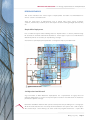
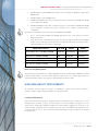
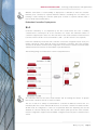
BPG | 11n DESIGN, IMPLEMENTATION AND OPTIMIZATION
Meru Best Practices Guide
Author | Robert Ferruolo | Technical Marketing Engineer
Date | JULY 2010
Version | BPG_11n_v1.0
MERU BEST PRACTICES GUIDE | 11n Design, Implementation and Optimization
TABLE OF CONTENTS
MERU BEST PRACTICES GUIDE | 11n Design, Implementation and Optimization
........................................................................................................................................................................................................2
INTRODUCTION ............................................................................................................................................................4
Conventions ..........................................................................................................................................................4
WLAN SYSTEM DESIGN..........................................................................................................................................4
General Data Collection ......................................................................................................................................5
Contact Information.............................................................................................................................................5
Organizational Structure.....................................................................................................................................5
GETTING TO KNOW THE INSTALLATION SITE ............................................................................................5
Floor Plans ...........................................................................................................................................................5
Network Topology ...............................................................................................................................................5
Existing Switch Specifications ...........................................................................................................................6
802.af PoE Usage.................................................................................................................................................6
802.3at PoE Usage...............................................................................................................................................6
Site Data Collection Form ...................................................................................................................................6
Pre-deployment Site Survey ..............................................................................................................................7
DETERMINING SYSTEM REQUIREMENTS ....................................................................................................7
Conduct Customer Interviews ............................................................................................................................7
Establish Wireless Requirements .......................................................................................................................7
Evaluate Current Wireless Environment ...........................................................................................................8
Establish Application Requirements..................................................................................................................8
Wi-Fi Clients .........................................................................................................................................................8
Establish Availability Requirements ..................................................................................................................8
Define Security Requirements ............................................................................................................................8
Detail Controller and VLAN Configuration Plans ..............................................................................................9
DESIGNING WLANS WITH THE AP300 ...............................................................................................................9
General Guidelines...................................................................................................................................................9
Network Time Service .........................................................................................................................................9
VLANs and WLANs - Wired and Wireless .........................................................................................................9
AP Density..........................................................................................................................................................10
Signal Strength..................................................................................................................................................10
SNR.....................................................................................................................................................................10
Virtual Port..........................................................................................................................................................10
Design Considerations AP300 VPort – Slow Clients .......................................................................................11
When to use WLAN Virtualization....................................................................................................................12
Virtual Cell Boundaries (Virtual Cell Domains)................................................................................................12
Channel Selection .............................................................................................................................................13
AP Connectivity L2/L3 .......................................................................................................................................13
DESIGN SCENARIOS .........................................................................................................................................14
Simple Office Deployment................................................................................................................................14
11n Migration from Microcell ...........................................................................................................................14
Outdoor...............................................................................................................................................................15
Vcell/Vport outdoors .........................................................................................................................................16
Warehouse .........................................................................................................................................................16
BPG_11n_v1.0 | Page 2
MERU BEST PRACTICES GUIDE | 11n Design, Implementation and Optimization
Multi-floor Deployments ...................................................................................................................................16
Multi-controller Deployments ..........................................................................................................................17
Inter Controller Roaming (ICR) .........................................................................................................................17
Migration from AP200 to AP300 .......................................................................................................................17
New 11n-only Deployments .............................................................................................................................18
High Availability Deployments ..............................................................................................................................18
Link-layer Redundancy ......................................................................................................................................18
Redundant Controllers Deployments...............................................................................................................19
AP Provisioned Redundancy .................................................................................................................................20
High Client Density Deployments.....................................................................................................................21
EzRF Location Manager Deployments .............................................................................................................22
Bridge ESS Profiles............................................................................................................................................24
DEPLOYMENT PROCESS .......................................................................................................................................25
AP Placement Plan .................................................................................................................................................25
AP300 Installation ...................................................................................................................................................25
Ceiling Mount.....................................................................................................................................................26
Wall Mount .........................................................................................................................................................26
AP300i Mounting ...............................................................................................................................................26
Proof of Concept Plan.............................................................................................................................................27
Deployment Plan ....................................................................................................................................................27
Acceptance Test Plan..............................................................................................................................................27
RF Interference .......................................................................................................................................................27
SUMMARY .................................................................................................................................................................28
BPG_11n_v1.0 | Page 3
MERU BEST PRACTICES GUIDE | 11n Design, Implementation and Optimization
INTRODUCTION
This document is intended to aid with the design, implementation and optimization of Meru
802.11n WLAN systems. Much of the information included in this document can be found
scattered about in many different sources, or in some cases, not written down but known by
a number of individuals that have a good deal of hands-on experience with Meru. This
document consolidates much of the wisdom acquired over the years and organizes it in a
form that makes it accessible to a wider audience.
This guide is by no means a substitute for User Guides, Configuration Guides, Application
Notes, etc. Throughout this guide we will refer to other documents that provide greater detail
for the subject at hand and when possible, links to those documents will be provided.
This document will make use of icons that will alert the reader about features that solve long
standing challenges with Wi-Fi as well as to identify key recommendations.
CONVENTIONS
Throughout this document icons will used to help identify features that are either unique to
Meru Networks or Meru recommendations.
The Meru icon below will signify that the feature described is unique to Meru Networks
WLANs.
The thumbs up icon shown below is an indication that a configuration recommendation
being offered.
WLAN SYSTEM DESIGN
Any successful deployment begins by first understanding all of the system requirements. A
good place to start is with Q and A sessions with all stake holders. Another useful tool is a
requirements questionnaire. The main objective behind this exercise is to ask all questions
and to get clear answers upfront so as to ensure that the outcome matches the expectation of
the customer.
Some of the initial items typically discussed are coverage requirements, client density
requirements, performance needs, security (including rogue detection) policies, SLAs (service
level agreements), are there aesthetic considerations, types of application that will be used,
non-pc devices to be used such as barcode scanners, outdoor coverage and location needs,
etc.
BPG_11n_v1.0 | Page 4
MERU BEST PRACTICES GUIDE | 11n Design, Implementation and Optimization
GENERAL DATA COLLECTION
Contact Information
Getting a complete list of contacts upfront will save time later in the project. One of the most
important contacts is the person or persons that will allow you to gain access to all of the
areas needed to perform the initial walkthrough, the installation and then later the validation.
Organizational Structure
Here we collect data about the organization. We find out who has the authority to approve
network design or implementation related questions. This is also where we identify the stake
holders. We need to identify who will be signing off on the project. We need to identify the
technical contacts that we will to work with from various departments.
GETTING TO KNOW THE INSTALLATION SITE
Another critical aspect of design process is getting to know the building or the physical
environment where the network will be installed. This process typically involves, getting a
copy of the floor plans, a site walkthrough and/or interviewing those that know what
materials were used in the construction of the building. The goal here is to know what
materials we are dealing with. Wrong assumptions made here could turn out to be very time
consuming and costly.
Floor Plans
Before we can come up with an AP placement plan we’ll need accurate (to scale) floor plans.
Sometimes getting a hold of up to date plans is not so easy. At times we have resorted to
getting fire escape plans that are posted on the walls of building in the US. A word of caution:
sometimes the fire escape diagrams are not to scale.
Network Topology
Understanding the wired network is obviously important as the Meru network rides over the
wired network (as an overlay). One must understand speed and feeds as well as L2 and L3
domains. Meru 11n APs have 10/100/1000 Ethernet interfaces. Will the existing switching
infrastructure be able to provide enough capacity to handle the potential through put of an
11n network?
While it is not a requirement that all 11n APs be connected via gigabit Ethernet it is
recommended.
BPG_11n_v1.0 | Page 5
MERU BEST PRACTICES GUIDE | 11n Design, Implementation and Optimization
Existing Switch Specifications
Meru Networks 11n AP300 series APs can operate at maximum 300Mbps dual stream 11N
data rates on both Wi-Fi band radios 802. 11bgn and 802. 11an concurrently while using the
most prevalent PoE switch port type, a single standard 802.3af or 802.3at port; however there
are a few configuration considerations with regards to MIMO that need to be taken into
account, please review chart below. Knowing the PoE capabilities up front can help ensure
optimal configuration from the start.
The recommendations for radio MIMO settings for power options are provided below.
802.af PoE Usage
When using System Director 3.6/4.0 and 802.3afPoE, Meru supports radios set to any MIMO
settings except 3x3 on dual radios. This is because two radios set to 3x3 MIMO using an
802.3af switch may not have enough power if the cable is too long. Shorter cables frequently
work, however. Meru supports:
•
•
•
Single 3x3 radio
Dual 2x2 radios
Dual radio with one set to 2x2 and the other one set to 3x3
When using System Director 4.0 and 802.3af, the AP300 MIMO configuration is limited to the
following:
•
•
3x3 for the 5 GHz radio
2x2 for the 2.4 GHz radio
802.3at PoE Usage
When using System Director 3.6/4.0 and 802.3at, the following radio combinations are
recommended:
•
•
•
•
Single 3x3 radio
Dual 2x2 radios
Dual radio with one set to 2x2 and the other one set to 3x3
Dual 3x3 radios are recommended with a limitation.
Use 802.3at power for two 3x3 MIMO radios when the switch has a high enough power
output to support all devices on the PoE.
Site Data Collection Form
The Meru Networks Professional Services team has created a Site Data Collection form to
assist with gathering the system requirements. This form will help ensure that important
questions are asked and answered at the start of the project. For a copy of Site Data
Collection form please contact Meru Professional Service.
BPG_11n_v1.0 | Page 6
Pre-deployment Site Survey
For Meru, pre-install site surveys are often not required. A site survey may be recommended
if the environment is particularly challenging such as cruise ships, manufacturing facilities,
cold storage facilities, warehouses, etc.
A sample pre-site survey will aid in determining optimal AP placement. A sample pre-site
survey is accomplished by identifying locations that are representative of the larger
installation site. Sample site surveys are performed in those locations. Using this method
allows us to get a good idea of the type of coverage that will be required throughout the
installation without requiring a survey of the entire site.
DETERMINING SYSTEM REQUIREMENTS
Conduct Customer Interviews
Here is where we discover the requirements of the wireless network. We need to gather
information about all of the applications that will be used, as well as the requirements for
performance, client density, system availability and security.
Again, it is very difficult to create a design without first knowing the requirements. Therefore
it is absolutely critical that this portion of the project be handled with the utmost attention to
detail and thoroughness.
Identify any specific pain points to solve if there is a previous wireless infrastructure.
Remember to solicit input from all stake holders!
Establish Wireless Requirements
Here is where we take a closer look at the wireless requirements. We ask questions such as:
• What are the coverage, density and RF requirements?
• Are there known sources of non Wi-Fi interference (e. g. 2.4 GHz cordless phones,
microwave ovens, etc.)?
• Are there sources of Wi-Fi interference from neighbors?
In hospitals there can be great number of sources of Wi-Fi and non Wi-Fi interference. For
example an MRI station and its console may have their own 802. 11 based connection and
there are high power microwave ovens used to warm heat packs used in physical therapy.
These types of devices will cause interference on the channels they are occupying.
Spectrum Scan
While the customer may have a good idea of the existing RF environment there may be
sources of interference that are unknown. This is where a spectrum analyzer will be of great
use. Knowing what is going on in the frequency ranges we intend to use is critical to the
success of a wireless network. Understanding if there are other sources of interference (i.e.
non Wi-Fi sources) can be the difference between a network the works some times and a
network the works all the time.
BPG_11n_v1.0 | Page 7
MERU BEST PRACTICES GUIDE | 11n Design, Implementation and Optimization
One of the big advantages with Meru is that once we have identified the channels that have
interference we can configure the Meru APs to be on different channels.
Evaluate Current Wireless Environment
This step involves leaning about the existing WLAN (if there is one). Will the new Meru
network coexist at anytime, anywhere with the existing network?
Establish Application Requirements
Not all applications come with the same set of throughput, latency, loss and jitter
requirements. It is important that we discover the details (e.g. application names, versions,
manufacturers, transport protocols, bandwidth and latency requirements, VoIP signaling
protocols used, ports used, etc.)
We’ll need to ask if multicast is required. Meru has some advantages over other vendors that
allow us to support multicast streaming video. However, a network configured to support
multicast video will be architected a specific way as far as VLANS and ESSs are concerned.
Knowing about this requirement up front is imperative to a successful deployment that
supports multicast.
Wi-Fi Clients
This task involves documenting the various types of clients that will use the WLAN. For
controlled environments this task is straight forward but for some environments where any
number of client types may be used (e.g. higher education) this task can be daunting.
Nevertheless it is always helpful to start with a list of known clients. This will help us build
our Proof of Concept and our Acceptance Test Plans.
Establish Availability Requirements
These requirements will vary from one type of installation to another. For example, hospitals
typically mandate system availability approaching 99.999% uptime, whereas universities are
typically satisfied with less demanding uptime requirements.
The availability requirements will influence the WLAN design so knowing them upfront is key
to a successful deployment. Again, remember to query all stake holders!
Define Security Requirements
This is where we ferret out all of the security policies and requirements. Make sure a dialog is
established with the team responsible for all things security related. Before getting into the
specifics about how the WLAN will be configured we should start by getting a solid
understanding of the security policies and philosophy of the organization.
BPG_11n_v1.0 | Page 8
MERU BEST PRACTICES GUIDE | 11n Design, Implementation and Optimization
We ask such questions as:
• Which RADIUS servers are they using?
• Will FIPS-140 be required?
• Which authentication and encryption types are to be used? Keep in mind that the
only two types of encryption that will realize the benefits of great data rate offered by
802.11n are clear (no encryption) and WPA2 per the specification. We also ask about
network management user roles. This task involves identifying who needs to do
what in the way of network management so that levels of access to EzRF Network
Manager can be configured as required.
Detail Controller and VLAN Configuration Plans
In this section we discuss a deep dive into the existing or proposed wired side of things. We
need to learn about the VLANs that are or will be in place. We need to plan ahead to integrate
effectively with them. Often times the recommendation is to allocate separate VLANS for
wireless clients. We also need to learn about the DHCP scopes and DNS addresses. We also
ask about spanning tree as this has Nplus1 implications.
Designing WLANs with the AP300
GENERAL GUIDELINES
In this section some general guidelines are presented. As with all such guidelines, they apply
to a wide variety of installations however they may not be applicable to a specific project that
you may be involved with.
Network Time Service
It is always best practice to use a Network Time Protocol service. Using NTP to sync all
networking gear is always advisable as it facilitates the correlation of events across diverse
systems for a give point in time. In a future publication we will detail network management
best practices.
VLANs and WLANs - Wired and Wireless
In terms of VLAN to ESS mappings, the Meru system allows one-to-one, one-to-many or
many-to-one (e.g. RADIUS assigned VLANs). This flexibility can easily accommodate the
existing switched L2 and L3 environments.
It is possible to have a single ESS (aka WLAN) mapped to a single VLAN on the wired side
that supports voice, video and data for example. Often this is the best configuration.
However there are cases where it is preferable to segment different traffic types on to
separate ESS profiles and VLANs. One common of example for this type of approach is
separating voice traffic for other types of traffic. Again, this is certainly not a requirement for
Meru Networks, it is recommended for the case when the switching network has segmented
voice traffic to a separate VLAN.
BPG_11n_v1.0 | Page 9
MERU BEST PRACTICES GUIDE | 11n Design, Implementation and Optimization
Another thing to consider when determining VLAN and ESS is whether or not multicast traffic
will be supported. While you can have multiple VLANs per ESSID it is not recommended as a
1-to-1 mapping VLAN to ESSID is required to support multicast traffic (e.g. push to talk voice,
streaming multicast video).
AP Density
We should be aware of how much APs overlap (i.e. the number of APs that can hear each
other). This can be determined by the number of neighbors shown in the wireless radio GUI
display. Note that in the past – particularly with AP200s and Vcell (Shared BSSID) we were
advised to be cognizant of how much AP overlap. With AP300 and Vport (Per Station BSSID)
overlap is a less of a concern but neighbor count should still be considered. If there are more
than 35 neighbors, consider channel layering. Which layering model you choose will depend
on the application requirements.
A good rule of thumb when determining the optimal AP density is that each and every
station, no matter where it is throughout the network, will be able to hear from 2 or 3 APs.
Signal Strength
The recommendation is for data only networks minimum signal strength of -70dbm
everywhere. For networks that will support voice and or multicast video we recommend
-65dbm or greater everywhere.
SNR
Another important metrics to consider when building a wireless network is the signal to noise
ratio (SNR).
The recommended SNR for data only networks is 20 or greater. For networks that will support
voice and/or video a SNR of 25 or greater is recommended.
Virtual Port
Virtual Port (Vport) is a new technique for virtualization of the WLAN. Virtual Port virtualizes
the BSS much like Virtual Cell (VCell) does however with Vport, the BSS that each client
associates to is unique to the client as opposed to Vcell where all clients associate to a
common BSS (for a given channel and ESS).
With Vport the clients unique BSS follows them as they travel around the network. Since the
client always sees a single BSS they never re-authenticate or re-associate as they get handed
off from AP to AP. This has profound implication for many applications, in particular RTP (real
time protocol) based apps such as VoIP and streaming video. There are many other
BPG_11n_v1.0 | Page 10
MERU BEST PRACTICES GUIDE | 11n Design, Implementation and Optimization
advantages of WLAN virtualization. For a more detailed look at this subject a link to a white
paper on WLAN virtualization follow the link below.
With Vport there is a “parent” BSS that is common to all clients for a given channel and ESS.
Just to be clear the clients never associate to the parent BSS when Vport is configured. The
parent BSS is used when load balancing is enabled which will be discussed later in this
guide.
http://www.merunetworks.com/pdf/whitepapers/
WP_increasing_reliability_of_virtualized_WLAN_0510_v2.pdf
Design Considerations AP300 VPort – Slow Clients
There are special considerations where Vport is used in the presence of slower clients. With
Vport each station gets their own beacon stream. Slower clients, in particular, 11b clients
beacon streams can take up an inordinate amount of airtime due to the slow data rate at
which they are transmitted.
Beyond the airtime utilization consideration there is the concept of an interference region (IR),
or the area that is consumed by a single transmission, thus preventing other clients from
successfully transmitting. With slower data rates the IR is considerably larger. With that in
mind there are a number of suggested guidelines when Vport and slower clients are in play.
The following illustration depicts relative airtime used by frames using different data rates.
Relative airtime utilization is represented by the horizontal bars to the right of each data rate.
The longer the bar, the greater the airtime utilization.
This next diagram shows how lower data rates can reach clients at greater distance from the
AP (and vice versa). The circles with the thinner line represent the distance that lower data
rate traffic can reach. The thicker lines represent higher data rate traffic.
BPG_11n_v1.0 | Page 11
MERU BEST PRACTICES GUIDE | 11n Design, Implementation and Optimization
There are a couple of general guidelines to follow when determining the number of channel
layers needed to accommodate the type and number of clients expected.
The recommendation is to design for 32 clients per radio. The following table provides
recommendations for maximum clients per interference region for given beacon data rates.
Beacon Data Rate
Interference Region Capacity
24 Mbps (g)
200
11 Mbps (b)
100
If you determine that extra channel layers are required it is recommended that the slower
clients use a channel dedicated for them. This will allow faster clients to take full advantage
of the other channel/s.
This document will go into detail of channel layering in the section to follow.
When to use WLAN Virtualization
Virtualization requires a uniform AP model with the exception of the AP300 and AP300i.
Virtualization will work across these AP models.
As a rule the recommendation is to use WLAN virtualization.
As of this writing, there is one exception to this rule and that is if Polycom SVP (Spectralink
Voice Protocol) is used. The reason for this is the SVP has its own way of doing CAC (call
admission control) where the SVP server keeps track of the number of calls per BSS. With
Meru Networks WLAN virtualization the BSS (or parent BSS in the case of Vport) is common
to all APs (for a given channel and ESS). With WLAN virtualization SVP CAC is effectively
disabled. For this reason SVP and WLAN virtualization are not well suited for one another.
It should be noted that the newer Polycom phones and firmware now come with support for
SIP. These phones when configured to use SIP work very well in a virtualized WLAN.
Virtual Cell Boundaries (Virtual Cell Domains)
A virtual cell boundary is where one virtualized BSS ends and another begins. The simplest
type of virtualized WLAN deployment is one large Virtual Cell across the network. In this case
there are no Vcell boundaries. If the network is large enough to require multiple controllers or
if the network has multiple AP types (e.g., AP200s and AP300s) within the same building for a
given network there will be Vcell boundaries.
BPG_11n_v1.0 | Page 12
MERU BEST PRACTICES GUIDE | 11n Design, Implementation and Optimization
When clients move across a Vcell boundary a hard handoff will occur, similar to a client
moving from AP to AP in a micro cell environment. This handoff will require a reauthentication and re-association (just as roaming between non virtualized APs would).
This type of handoff is suboptimal and should be avoided if possible.
Inter Vcell roaming can be minimized if care is taken when determining the boundary
locations for give installation. When determining the optimal Vcell boundaries use the
buildings natural attenuation properties to try and isolate one Vcell for the other. For example
if there is a six story building with two controllers, use controller 1 on floors 1, 2 and 3 and
use controller 2 for floors 4, 5 and 6. This way inter Vcell roaming only occurs when clients
roam between floors 3 and 4.
Channel Selection
Again, the recommendation is to use a spectrum analyzer to determine the best channel/s to
deploy. The goal here is to identify sources of non Wi-Fi interference that may be present at
the site/s. One of the most common sources of interference is microwave ovens which
typically have more of a negative impact on 6 through 14 in the 2.4GHz spectrum.
Of course RF environments change so this step of selecting the cleanest channel at the time
of deployment does not guarantee an interference (non Wi-Fi) free channel forever;
nevertheless it is always worth the time and effort to select the cleanest channel from the
start.
Of course with Meru Networks pervasive coverage can be provided by using a single
channel. All of the other channels are available to channel layer where needed to support
high client densities or high throughput applications.
Absent analysis use channel 1 in 2.4GHz and channel 44 – 48 in 5GHz.
Channel 1 is recommended as it will not be as susceptible to microwave ovens. Channel 6 is
not recommended for two reasons: it the default channel for most APs and microwave ovens
can interfere with this channel as well. In the 5GHz range channel 44 – 48 (40MHz) are
recommend as most APs default to channel 36. Keep in mind that some clients do not
support UNI-III (which limits recommendation the UNI-I channels) so verify client support for
the upper channels (i.e. 149 – 165) before deploying UNI-III channels.
AP Connectivity L2/L3
When choosing between L2 or L3 deployment one must consider not only the way the wired
network is (or will be) deployed but also the number of other applications that will be
deployed. E.g., Location Manager, SAM.
Another consideration when determining L2/L3 is which redundancy scheme is used. For
example, with the option 43 redundant controllers and NPlus1 features, L3 connectivity is
required.
The general recommendation is to use L3 connectivity.
BPG_11n_v1.0 | Page 13
MERU BEST PRACTICES GUIDE | 11n Design, Implementation and Optimization
DESIGN SCENARIOS
This section introduces the various types of deployments and offers recommendation for
various scenarios as listed below.
There are many types of deployments such as typical office space, hotels, hospitals,
outdoors, warehouses, stadiums, those that require location tracking, bridged (remote) APs,
etc.
Simple Office Deployment
Let’s consider the typical office building that uses drywall offices or cubicles, with few large
RF obstructions and little external RF interference. For this type of space a tool like Ekahau’s
Site Survey will do an accurate job of predicting coverage.
A screenshot of pre-deployment predictive coverage heat map is provided below.
11n Migration from Microcell
A good number of Meru Networks’ deployments are a replacement of legacy microcell
networks. Many times a one-for-one rip and replace results in more APs than are needed to
provide the optimal coverage.
Remember that Meru Networks APs operate at full power thus providing more coverage per
AP. In the event that there are more drops than needed there are options. One could not place
APs at extra drops -- thus lowering cost of the solution by a significant amount -- or place APs
BPG_11n_v1.0 | Page 14
MERU BEST PRACTICES GUIDE | 11n Design, Implementation and Optimization
at every location but configure half of them for different channels -- thus doubling the
available client and/or throughput capacity.
Let’s expand on the latter example further. We now have 4 radios to work with for each area
of the network. Let’s assume that the customer has some mix of 11a, 11b, 11g and 11n
clients. We could configure the radios as follows:
AP1/Radio1: Channel 1 (11b and 11b/g clients only)
AP1/Radio2: Channel 36 (11a clients only; voice handsets perhaps)
AP2/Radio1: Channel 6 – 11 (11n clients only)
AP2/Radio2: Channel 44 – 48 (11n clients only)
Another option would be to create channel layers with load balancing enabled but we need to
be careful here because the typical microcell AP drop layout does not lend itself to an optimal
channel layer load balancing deployment. More about channel layer load balancing later in
this document.
If APs are swapped out one-for-one and APs are placed on the same channel you may need
remove the lower base rates to shrink the interference region. It may also be necessary to
adjust the probe response threshold. Lowering the probe response threshold allows the APs
to ignore probe requests from clients that are farther away or below the threshold.
Please contact Meru Networks customer support for assistance with lowering probe response
thresholds. In the case of a rip and replace (one-to-one or not) plan to do a post deployment
site survey to check for coverage holes and see if we have achieved the goal of 2 to 3 APs
visible at any location throughout the network.
In the event that there is coverage hole, an AP can be placed in that area. It is not required to
adjust other AP locations.
Outdoor
AP300 must be put into NEMA enclosures. Do not use and indoor cable patch (RJ-45 to
RJ-45) outdoors as they will not hold up to the varying weather conditions. Another option is
to keep the AP300 indoor and just mount the antennas outside.
Lightning arrestors are required by code in the US. Lightning arrestors create some level of
loss so you’ll want to compensate for that loss and that of the patch cable when configuring
antenna gain.
The two types of arrestors used most commonly are gas discharged and solid core. The solid
core types appear to have less dB loss and from anecdotal evidence which seem to be
preferred for 11n networks. Both types are consumables and are limited to one time use.
One must pay careful attention to the height that the APs will be mounted as it relates to
antenna selection. For example, if the APs are mounted on a 50’’ pole the default omni
antennas would be a poor choice as the coverage provide at the ground level would poor.
The recommendation for antennas in this case would a directional or an omni with down tilt.
BPG_11n_v1.0 | Page 15
MERU BEST PRACTICES GUIDE | 11n Design, Implementation and Optimization
Vcell/Vport outdoors
Let’s take the example of a big open area. The spacing between APs is going to be much
greater than that of indoors.
If coverage is pervasive – with the recommended SNR and or signal strength levels (-65dBm
for voice and -70dBM for data only) – then the recommendation is to enable virtualization. If
on the other hand coverage is spotty outdoors, the recommendation is to configure single
channel but with virtualization disabled.
Warehouse
Warehouses are one of the most challenging environments you will encounter, the other
being hospitals. One of the main characteristics of warehouses that make them a challenging
environment for Wi-Fi is high ceilings.
The recommendation is to orient the default omni antennas horizontally. The other option is
to use directional antennas. When directional antennas are used, there are often deployed on
walls and mounted in such a way so their coverage is directed down a particular isle.
Another potential challenge is rows of shelves (often made out of metal). Then there is the
issue of what is stored on the shelves and when it is stored or not. For example, if the shelves
are loaded with containers of liquids the coverage patterns will be much different than if the
shelves were empty or store material that has less of RF attenuating properties.
When you survey first do it under fully-loaded conditions, during normal business operations
including when devices are in motion. This is critical for warehouses.
Another thing to consider with warehouses is the velocity of the clients. Many clients travel
around on forklifts so they have the potential of roaming from one AP to the next faster than
a person carrying a client would. The Meru Networks system is by default optimized for the
speed of typical human walking around. There are tweaks than can be made to accommodate
higher velocity clients.
For details on how to tune the system to accommodate faster client roaming please contact
Meru Support.
Multi-floor Deployments
The question of using alternating channels for different floors in multi-floor deployments is
often raised. While there may be situations where this is advantageous it is not generally
considered the best practice.
Use the same channel channels across floors. We do not recommend using different
channels across floors as this practice limits the capabilities of virtual cell. Use channel
layering to accommodate higher client densities and/or higher throughput requirements.
And remember to stagger AP placement between floors when designing for locationing.
BPG_11n_v1.0 | Page 16
MERU BEST PRACTICES GUIDE | 11n Design, Implementation and Optimization
Multi-controller Deployments
Excluding when the Inter-Controller Roaming (ICR) feature is used, roaming between
controllers would results in a hard handoff (i.e., Authentication/Association/DHCP) and a new
IP address being issued to the client. Again, plan where hard handoffs will happen. Use
natural boundaries.
Another consideration is VLAN assignments in a multi-controller deployment. The
recommended best practice is to use different VLAN addresses on different controllers.
Inter Controller Roaming (ICR)
Inter-controller roaming preserves client IP address when roaming from one controller to
another. ICR enables clients to roam between controllers without interrupting client
application sessions.
The recommendation is to use ICR when IP retention is a requirement.
Migration from AP200 to AP300
When migrating from AP200 to AP300 it is generally recommended that the migration
happen in big chunks, so to speak. A migration process that proceeds floor by floor or wing
by wing will typically be less disruption to network availability.
There is a possibility of over deployment with the method of one-to-one replacement as the
AP300, with its ability to do MIMO, has the potential to provide greater coverage per AP than
AP200. If it is determined that there are too many APs, some APs may be decommissioned.
If external antennas were used on the AP200, only two leads were used to connect the
antennas to the AP. With the AP300 there are 6 antenna connectors. To reuse the antennas
that were previously used by the AP200 (with just 2 leads) the 4 extra/unused leads of the
AP300 will need to be terminated. This type of configuration is supported in build 3.6.1-MR4
or later.
2.4 GHz: use A6, terminate A4 and A5.
5 GHz: use A1, terminate A2 and A3.
Summary of Recommendations for network comprised of AP200s and AP300s
The following best practices should be followed to get optimal performance from a network
that includes both AP200s and AP300s.
Here are the assumptions for best practices below.
BPG_11n_v1.0 | Page 17
MERU BEST PRACTICES GUIDE | 11n Design, Implementation and Optimization
•
AP200 using per station BSSID Vcell (There are no problems if AP200 is using shared
BSSID Vcell)
•
AP300 using per station BSSID Vcell
•
AP200 and AP300 on the same channel (There are no problems if AP200 and AP300
are on different channels)
•
AP200 and AP300 on the same controller (There are no problems if AP200 and AP300
are on different controllers and each controller has a unique "controller index"
configured.)
Best Practices for networks that are made up of AP200s and AP300s.
•
Try to avoid having AP200 and AP300 deployed in the same physical location,
Regionalize them
•
If the APs do have overlapping coverage, care must be taken to make sure the ESSID
profiles on both AP types are unique. The example below shows 2 scenarios first is
supported while the second is not supported.
Supported scenario
ESS/SSID AP200
AP300
Unique ESS profiles on AP200 and AP300
ESS Profile UniqueName1
UniqueName2
SSID shared on AP200 and AP300
SSID
SameName
SameName
Non Supported Scenario
Same ESS profiles on AP200 and AP300
ESS Profile SameName
SameName
SSID shared on AP200 and AP300
SSID
SameName
SameName
New 11n-only Deployments
The general recommendation is to deploy 40 MHz channels in 5GHz bands, 20MHz in 2.4 GHz
band. Dedicate 5GHz to 11n-only clients. Support 11b/g clients on a single 11b/g channel on
separate AP/radio. Need to use Cat-5e (or better) Ethernet cable for APs.
HIGH AVAILABILITY DEPLOYMENTS
All controller models support a variety of redundancy options. This sections outlines a
number of ways in which high availability can be implemented.
Link-layer Redundancy
Every controller has the ability to support link-layer redundancy. This is where two or more
Ethernet ports are used in either an active-active or an active-standby configuration. In an
active-active configuration different VLANs are trunked (802.1q tagged) on the ports. In an
active-standby configuration the secondary port (e. g. G2) is in standby mode until link in lost
on the primary port (e. g. G1). In the event that the primary port goes down, the secondary
port takes over.
BPG_11n_v1.0 | Page 18
MERU BEST PRACTICES GUIDE | 11n Design, Implementation and Optimization
Whether active-active or active-standby is deployed it is advisable to have the controller
Ethernet ports connected to separate Ethernet switches (excluding the case where port
bonding is used). Having the controller uplink ports “homed” to separate switches adds a
level of wired network redundancy.
Redundant Controllers Deployments
N+1
Controller redundancy is accomplished by the N+1 model where we have a standby
controller that is a backup for all of the controllers in a cluster. The maximum number of
controllers supported per cluster is 5. All controllers in the cluster (master/s and slave) need
to be the same model. N+1 is a licensed feature. (If N = 1, an N+1 license is not required.)
In the N+1 redundancy model the slave controller can assume configuration state of any one
master controller at a time, where N can be 1-5 production controllers. The slave controller
assumes the IP address and last saved configuration of the master controller for which health
advertisements have not been received within a specified interval..
The following image is an illustration of an N+1 setup where N=5.
All controllers must be the same model number and be running the release of System
Director. All controllers must be on same L2 subnet.
The use of static IP is always recommended for controller IP addresses and for N+1 it is
mandatory. Be sure to have sufficient AP licenses on the slave controller for failed-over APs.
All APs must be configured to connect as L3 preferred when N>1. Spanning tree should
disabled on controller switch ports. The controller switch uplink port for the slave controller
must be configured to support all of the VLANs configured on the any of the controllers in the
cluster.
BPG_11n_v1.0 | Page 19
MERU BEST PRACTICES GUIDE | 11n Design, Implementation and Optimization
Four key characteristics of the N+1 redundancy model are as follows:
1. Slave and Master controllers that make up the N+1 cluster must all reside on the
same IP network so the slave controller can gratuitously ARP on behalf of the IP
address for the master controller for which it is providing backup services
2. APs must be a layer 3 hop away from their redundant controller cluster when N > 1
3. Master to Slave configurations are synchronized each time configurations are saved
via Web interface or CLI session.
4. When a slave controller is active, meaning it is actively providing +1 backup services
for one of the masters in the cluster, monitoring of the other masters if applicable
(where N > 1) will be put on hold until the master for which it is providing backup
services has rejoined the cluster and assumed production services.
AP PROVISIONED REDUNDANCY
Meru Networks AP Primary/Secondary controller redundancy option allows Meru access
points to be configured with a primary and secondary controller, should the primary
controller stop responding the APs they then connects to their configured secondary
controller via a DNS resolvable host name or IP address provided by DHCP option 43 vendor
specified attribute.
Three key characteristics of the AP Primary/Secondary controller model are as follows:
1. The primary and secondary controllers can be deployed on diverse IP networks (I. e.,
across Metro Ethernet networks or WAN services)
2. APs must be a layer 3 hop away from their redundant controller
3. Configuration changes between primary and secondary controllers must be manually
kept in sync
Redundant Controllers Configured via Option 43
AP can get controller assignment from a DHCP server. This method of controller assignment
is accomplished by using the Option 43 feature in the DHCP server.
Configuration of Option 43 on the DHCP server is basically the same as when only a single
controller is configured. The difference is that when the second controller is added it needs to
be delimited from the first controller by the use of a single comma (e.g.
192.168.1.1,192.168.1.2). Note that there are no spaces between the controller IP addresses or
the comma.
It should also be noted that there is no way to configure multiple controllers from the CLI or
the GUI. Option 43 is the only way to configure two controllers for the AP. The maximum
number of controllers configurable is two.
Caution: APs that are configured with redundant controllers via Option 43 will continually poll
for their primary controller (i. e., the first controller listed). If that controller becomes
reachable again the APs will reboot and connect back to the primary controller.
BPG_11n_v1.0 | Page 20
MERU BEST PRACTICES GUIDE | 11n Design, Implementation and Optimization
Redundant Controllers via DNS
Another way of implementing controller redundancy is with the help of DNS. This method is
often preferred as it is simple to configure. The following shows how to set things up on the
DNS.
DNS entry wlan-controller = primary controller
DNS entry wlan-controller2 = secondary controller
RF Redundancy
RF Redundancy is built into the typical Vcell deployment. If you recall we previously stated
that at each location 2 or 3 be visible. If this practice is followed we could lose an AP
anywhere and still provide pervasive wireless service. For additional layers of RF redundancy
more radios per location can be added.
High Client Density Deployments
Some examples of high client density deployments are auditoriums, stadiums, cafeterias,
intensive care units.
The ability to provide enough capacity for high client density deployments is one of the
strengths of the Meru architecture. As client density scales we can add channel layers.
Anytime high client densities exist consider channel layer with load balancing enabled.
As mentioned previously, virtual port has unique Beacon streams for each client. In high
density deployments these beacon streams can consume a considerable portion of available
channel bandwidth. To lessen the impact on channel usage of beacon stream we should
remove 1-2 Mb/sec base rates on the ESS profiles. This way beacons are transmitted at
higher data rates, which results in less time consumed for management overhead.
In the simplest form of channel layering it is just a matter of deploying dual radio APs and
applying the ESS profiles to both radios. By doing this we have two channels – one in 2.4GHz
and one in 5GHz -- where all services are present. If service is disrupted on either channel due
to a local source of interference (e.g. microwave oven) there is another channel available.
This approach has limitation. For instance, load balancing does not work across spectrums.
Additionally, some clients do not support both bands.
Load Balancing with Channel Layering
As mentioned previously Meru Networks WLAN systems have the ability to use channel
layering to provide additional capacity where needed.
Another feature available is Load Balancing (LB). With LB clients are evenly distributed across
all available channels (within a given spectrum).
For this type of LB to work two or more APs must be co-located. These APs need to be placed
approximately 7 – 10 ‘’ apart.
BPG_11n_v1.0 | Page 21
MERU BEST PRACTICES GUIDE | 11n Design, Implementation and Optimization
This distance is important as we do not want the APs so close to each other such that there
would be sideband or adjacent channel interference. Nor do we want them too far apart such
that the coverage patterns for the various channels differ greatly.
With two APs (or more) co-located we now have the ability have two channels in each
spectrum. This allows us to have redundancy in the 2.4GHz band as well as in the 5GHz band.
The image below is an example of how channel layers can be deployed to support high client
density areas such as an auditorium. In this example there are three ESSIDs: auditorium,
campus and voice. LB works within a specific ESS. For LB to work there must be at least two
channels in the same spectrum that have an ESSID in common.
In the example below LB is enabled on just the auditorium ESSID.
Notice that there is a “student” SSID that spans two ESSIDs (campus and auditorium). With
this single SSID available everywhere clients only need to associate to a single SSID. This
way there can roam from areas where there is no LB to areas where LB is enabled without
changing the SSID they are connected to. The above illustration also shows a “voice” SSID
and ESSID that is deployed pervasively.
EzRF Location Manager Deployments
Meru Networks partners with Newbury Networks for the Location Manager (LM) solution.
This solution works on “fingerprinting” rather than simple triangulation. Fingerprinting
considers the unique RF characteristics of each location in the environment when making a
location calculation. This technique provides greater precision than triangulation.
BPG_11n_v1.0 | Page 22
MERU BEST PRACTICES GUIDE | 11n Design, Implementation and Optimization
To begin the fingerprinting process floor plans are imported in the LM application. These
floor plans are then divided into “locales”. In the screenshot below each green and blue
section corresponds with a unique locale.
Fingerprinting is accomplished by the following steps:
(a)
(b)
(c)
(d)
(e)
(f)
Associate the fingerprinting client to the network
Start a continuous ping from that client to some other device on the network
Connect the fingerprinting to the LM
Move the client to a “locale”
Be sure that the fingerprinting communicating to the LM
As the client is transmitting data to the LM, rotate the client 360 degrees.
This process is repeated for all locales. While this process is happening all of the APs that can
hear the client at each locale are reporting back to the LM. Allocate enough time to do
fingerprinting. It general takes approximately 1 min / locale.
One considerable difference between general network designs and designs specifically
optimized for locationing is the density of APs seen in each location.
While the general guideline is for 2 – 3 APs be seen by a client, for locationing the
recommendation is that the range be increased to 5 - 7 APs. This allows for greater
locationing precision. An additional recommendation, that is a divergence from the general
APs placement guidelines, is that APs be installed in non-uniform AP pattern to support LM.
That is to say that the APs should be placed in an irregular pattern, both horizontally and
vertically in a multi floor deployment. This will guarantee unique fingerprints for each locale.
Please note the Location Manager requires a dedicated SA1000 as the application is very
processor intensive.
BPG_11n_v1.0 | Page 23
MERU BEST PRACTICES GUIDE | 11n Design, Implementation and Optimization
Bridge ESS Profiles
Traffic can be tunneled back to the controller or be bridged locally. There is a setting in the
ESS profile that sets the ESS to tunneled (default) or bridged. An AP300 can have both types
of ESS profiles on a single radio.
A tunneled ESS is generally the preferred method; however there are network designs where
it makes more sense to keep data traffic local. This is where bridged ESS profiles make sense.
For example, if there is a branch office that does not have a controller on site but does have
their own set of IT servers local, it would not be desirable for traffic to traverse WAN links
(twice) to get to those local services. With bridged ESS profiles the local traffic stays local.
The table below lists which features are/are not supported with bridged ESS Profiles.
Feature
Supported
Virtual Port
Yes
Band Steering Asset Tag Tracking
(Aeroscout)
802.1x Radius-based Mac
Filtering Locationing
Yes
L2/L3 discovery
DHCP option 43-based AP
discovery
Load Balancing
Rogue detection/
mitigation
IPV6, Apple Talk, Air
Fortress forwarding 802.1q VLAN Tagging
Yes
Yes
Yes
Yes
Yes
Yes
Yes
Yes
Yes
Meru QoS-rule based QoS No
Station MELF Event
No
(Station-log) IGMP Snooping
No
Captive Portal No
Inter Controller Roaming No
UDP broadcast control
RADIUS Assigned
Dynamic VLANs
Captive Portal No
Call Admission Control
No
No
No
BPG_11n_v1.0 | Page 24
MERU BEST PRACTICES GUIDE | 11n Design, Implementation and Optimization
Deployment Process
The first thing to keep in mind is that with any deployment (large or small) issues will arise.
The success of an install very much depends on when the issues reveal themselves and how
quickly they are rectified.
This section suggests taking a methodical approach to deployments that will help ferret out
issues early on in the process so they can be addressed in a timely manner.
AP PLACEMENT PLAN
Developing an AP placement plan does not always require the use of a modeling/survey tool
such as Ekahau Site Survey. There will be installations where placing APs every 60 – 70 feet
is sufficient for optimal coverage. These simple installations are characterized by a uniform
structure where it is relatively trivial to predict coverage patterns of the APs.
When a coverage planning is required, due to highly irregular building designs, contractual
agreement or some other reason, the recommended tool to use is Ekahua Site Survey. It is a
good tool in general but it also has specific knowledge about how Meru works.
AP300 INSTALLATION
There has been much discussion about optimizing antenna pattern on the AP300. It is beyond
the scope of this document to go into RF radiation patterns resulting from various antenna
position combinations.
We offer the following recommendations based on feedback from our customer base and the
Meru Networks Professional Service team.
BPG_11n_v1.0 | Page 25
MERU BEST PRACTICES GUIDE | 11n Design, Implementation and Optimization
Ceiling Mount
Wall Mount
AP300i Mounting
The AP300i has six internal antennas. This AP can also be mounted on the ceiling or wall.
The AP300i and AP300 are similar in many ways; one way they differ is in antenna patterns.
The AP300 omni antennas (default) provide 360 degree coverage. The AP300i’s internal
antennas provide 180 degree coverage (radiating from the top of the AP). This is something
to keep in mind when developing an AP Placement Plan.
BPG_11n_v1.0 | Page 26
MERU BEST PRACTICES GUIDE | 11n Design, Implementation and Optimization
PROOF OF CONCEPT PLAN
A good PoC plan includes testing (on a small scale) all of the WLAN system features and user
applications in a design that is representative of the planned installation. The main object
being to prove that the proposed system will be able to support the all of the functionality
required.
DEPLOYMENT PLAN
We have all heard about installations that did not go well. It is safe to say that many of these
installs share one thing in common and that is poor planning… You can have the best
product, design, installation team, etc, but without a solid, well thought out deployment plan,
the deployment will not be successful.
At a high level the plan details all of the tasks needed to pilot, install, optimize and validate
the WLAN system. The plan should also detail a back-out procedure in the event that service
impacting issues arise during the deployment.
The initial phase of the plan typically involves a pilot where a small section of the network is
deployed. This is like the PoC but now we are using production systems, applications and
clients. Once the pilot proves to be successful we can proceed with the rest of the
deployment.
ACCEPTANCE TEST PLAN
The acceptance test is built around the customer’s expectations in terms of network and
application performance. This test is a way of demonstrating conformance to a set of
customer requirements and it allows us to “deliver” the network to the customer. That is to
say, it is a way to put closure on the installation of the network thus completing the project.
It is also a way to manage project scope creep. A link to an example Acceptance Test is
provided below for reference.
It is highly recommended that sign-off (yes, in writing) be part of the acceptance testing
process. This will help prevent project scope creep and draw a close to this phase of the
project.
RF INTERFERENCE
A spectrum analyzer allows you to determine the channels that have the least amount of
interference (Wi-Fi and non Wi-Fi). Many assume that the 5GHz band is free of non Wi-Fi
interference. While it is true that 2. 4GHz has a greater number of devices that operate in that
spectrum; there are many non Wi-Fi devices that operate in the 5GHz band.
It is always a good idea to get a good picture of channel usage up front thus allowing for the
best channel selection at the time of the installation.
BPG_11n_v1.0 | Page 27
MERU BEST PRACTICES GUIDE | 11n Design, Implementation and Optimization
Summary
This guide was created to assist with the design, implementation and optimization of a Meru
Network WLAN. While many of the methods suggested can be applied to general WLAN
deployments, a number of recommendations were offered that are specific to Meru Networks
WLANs. Many of these recommendations come by way of feedback from engineers that have
performed numerous successful implementations over the years. This is just the first edition
of the 11n Best Practices Guide. As more wisdom is gained through more system
implementations we will provide updates to this guide to include the latest feedback from the
field.
BPG_11n_v1.0 | Page 28