1
Installation instructions
For the heating engineer
Installation instructions
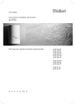
VRC 470f
GB, IE
Table of contents
Table of contents
1
1.1
1.2
1.3
1.4
1.5
1.6
Notes on the installation instructions ..............4
Observing other applicable documents ................4
Document storage ......................................................4
Symbols used ...............................................................4
Applicability of the instructions ..............................4
CE label .........................................................................4
Glossary.........................................................................4
8
8.1
8.1.1
8.1.2
8.2
8.2.1
8.2.2
2
2.1
2.1.1
2.1.2
2.2
2.3
2.4
2.5
Safety ............................................................................5
Safety and warning information .............................5
Classification of warnings .........................................5
Structure of warnings ................................................5
Intended use ................................................................5
Basic safety instructions...........................................5
Requirements for cables ...........................................6
Directives, laws and standards ................................6
8.2.3
8.2.4
8.2.5
8.2.6
8.2.7
8.2.8
8.2.9
3
3.1
3.2
3.3
3.4
3.5
System description .................................................. 7
System design.............................................................. 7
Functionality................................................................. 7
Appliance design .........................................................8
Identification plate .....................................................8
Accessories...................................................................8
4
4.1
4.2
4.2.1
4.2.2
4.2.3
4.3
4.4
4.4.1
4.6
Installation ..................................................................9
Checking the delivery ................................................9
Requirements for the installation site ...................9
Radio receiver unit .....................................................9
Controller ......................................................................9
Outside temperature sensor/transmitter..............9
Fitting the radio receiver unit in the boiler ..........9
Wall-mounting the radio receiver unit ................. 10
Removing the radio receiver unit from the
wall-mounting base .................................................. 10
Secure the wall-mounting base to the wall ..........11
Fitting the radio receiver unit..................................11
Fitting the outside temperature sensor/
transmitter ...................................................................11
Fitting the controller .................................................13
5
Electrical installation .............................................14
6
6.1
Start-up .......................................................................15
Overview of Installation assistant set-up
options ..........................................................................15
Making settings for the operator ...........................16
Setting other parameters for the heating
system ..........................................................................16
4.4.2
4.4.3
4.5
6.2
6.3
7
7.1
7.2
Operation ....................................................................17
Overview of menu structure ...................................18
Overview of Installer level ..................................... 20
8.2.10
8.2.11
8.2.12
8.3
8.3.1
8.3.2
8.3.3
8.4
8.4.1
8.4.2
8.4.3
8.4.4
8.4.5
8.4.6
8.4.7
8.4.8
8.4.9
8.4.10
8.4.11
8.4.12
8.4.13
8.4.14
8.4.15
8.4.16
8.5
8.5.1
8.5.2
8.5.3
2
Description of functions .......................................27
Service information ..................................................27
Entering contact details ..........................................27
Entering the service date .......................................27
System configuration: System ...............................27
Reading the system status .....................................27
Reading the water pressure of the heating
system .........................................................................27
Reading the DHW heating status ..........................27
Reading the collector temperature ......................27
Setting the frost protection delay ........................28
Setting the pump blocking time ...........................28
Setting the maximum preheating time ...............28
Setting the maximum pre-switch-off time..........28
Setting the temperature threshold for
constant heating .......................................................28
Setting the raising temperature............................29
Reading the software version ................................29
Configuring the heating circuit .............................29
System configuration: Heat generator ................29
Reading the status of the heat generator ..........29
Reading the value of the VF1 temperature
sensor ..........................................................................29
Activating the low loss header .............................29
System configuration: HEATING 1 and, if
relevant, HEATING 2.................................................29
Activating the heating circuits .............................29
Reading the end of the current time period ......29
Setting the target room temperature ................. 30
Reading the current room temperature............. 30
Setting the set-back temperature (set-back
temp.).......................................................................... 30
Reading the target flow temperature ................. 30
Reading the current flow temperature............... 30
Reading the status of the heating circuit
pump ........................................................................... 30
Reading the status of the heating circuit
mixer valve ................................................................ 30
Activating room temperature control ............... 30
Activating automatic summer time detection.. 30
Setting the heating curve ........................................31
Setting the minimum flow temperature for
heating circuits ...........................................................31
Setting the maximum flow temperature for
the mixing circuit .......................................................31
Reading the status of advanced functions ..........31
Specifying control modes outside time
periods ..........................................................................31
System configuration: Domestic hot water ........32
Setting the target temperature for domestic
hot water cylinder (desired hot water
temperature) ..............................................................32
Reading the current temperature of the
domestic hot water cylinder ..................................32
Reading the status of the cylinder charge
pump ............................................................................32
Installation instructions VRC 470f 0020124645_00
Table of contents
8.5.4
8.5.5
8.5.6
8.5.7
8.5.8
8.5.9
8.5.10
8.6
8.6.1
8.6.2
8.6.3
8.6.4
8.6.5
8.6.6
8.6.7
8.6.8
8.6.9
8.6.10
8.6.11
8.6.12
8.6.13
8.6.14
8.6.15
8.6.16
8.6.17
8.6.18
8.6.19
8.7
8.7.1
8.7.2
8.7.3
8.8
8.9
8.10
8.11
Reading the status of the circulation pump ......32
Defining the day for executing the
anti-legionella function ...........................................32
Defining the time for executing the antilegionella function ....................................................32
Defining the offset for charging the
domestic hot water cylinder ..................................32
Defining the run-on time for the cylinder
charge pump ..............................................................32
Activating parallel charging (domestic hot
water cylinder and mixing circuit) ........................33
Setting the relay output for the cylinder
charge pump and circulation pump .....................33
System configuration: Solar ...................................33
Reading the value of the SP2 cylinder sensor ..33
Reading the value of the solar gain sensor .......33
Reading the status of the solar pump .................33
Reading the value of the TD1 sensor ...................33
Reading the value of the TD2 sensor ..................34
Reading the status of the multi relay ..................34
Reading the runtime of the solar pump..............34
Resetting the runtime measurement of the
solar pump..................................................................34
Activating the solar pump on temperature
difference control .....................................................34
Defining the priority for charging the
domestic hot water cylinder ..................................34
Setting the flow volume of the solar circuit ......34
Defining the multi relay setting ............................34
Activating the solar pump kick..............................34
Setting the solar circuit protection ......................35
Defining the maximum temperature for the
solar cylinder .............................................................35
Defining the on temperature difference
value for solar charging ..........................................35
Defining the off temperature difference
value for solar charging ..........................................35
Defining the on temperature difference
value for second difference control .....................35
Defining the off temperature difference
value for second difference control .....................36
Radio communication system configuration......36
Checking radio communication between
controller and radio receiver unit.........................36
Checking radio communication between
outside temperature sensor/transmitter and
radio receiver unit ....................................................36
Commissioning a replacement radio controller
(teach-in) .....................................................................36
Selecting the expansion module for sensor/
actuator test ..............................................................36
Activating the screed drying function ................36
Changing the code for Installer level ...................37
Operator level functions .........................................37
Installation instructions VRC 470f 0020124645_00
9
Handing over to the operator .............................38
10
10.1
10.2
10.3
Fault detection and elimination .........................39
Error messages .........................................................39
List of errors ............................................................. 40
Restoring factory settings ..................................... 40
11
11.1
11.2
11.2.1
11.2.2
11.3
11.4
11.4.1
11.4.2
11.4.3
11.4.4
11.4.5
Replacing components ...........................................41
Recording radio controller settings.......................41
Replacing the radio receiver unit ..........................41
Removing the faulty radio receiver unit .............41
Fitting the new radio receiver unit ........................41
Replacing the outside temperature sensor/
transmitter .................................................................42
Removing the faulty outside temperature
sensor/transmitter ....................................................42
Activating and fitting the new outside
temperature sensor/transmitter .......................... 44
Replacing the radio controller .............................. 44
Removing the faulty radio controller.................. 44
Fitting the new radio controller ........................... 45
Radio receiver unit: starting teach-in ................. 45
Radio controller: activating teach-in................... 45
Radio controller: restoring recorded settings... 45
12
12.1
12.2
Warranty and customer service........................ 46
Vaillant warranty ...................................................... 46
Vaillant Service......................................................... 46
13
13.1
13.2
13.4.1
13.4.2
13.4.3
Decommissioning ....................................................47
Decommissioning the controller ...........................47
Decommissioning the outside temperature
sensor/transmitter ....................................................47
Decommissioning the radio receiver unit ...........47
Recycling and disposing of the controller,
radio receiver unit and outside temperature
sensor/transmitter ................................................... 48
Devices ....................................................................... 48
Packaging................................................................... 48
Batteries ..................................................................... 48
14
14.1
14.2
14.3
Technical data ......................................................... 49
VRC 470f controller ................................................ 49
Radio receiver unit .................................................. 49
Outside temperature sensor/transmitter........... 49
15
Glossary .................................................................... 50
11.3.1
11.3.2
13.3
13.4
Index ......................................................................................52
3
1
1
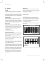
Notes on the installation instructions
Notes on the installation
instructions
The following instructions are intended to guide you
throughout the entire documentation. Further documents apply in combination with these installation
instructions.
We accept no liability for damage caused by failure to
observe these instructions.
1.1
Observing other applicable documents
> Always observe all installation instructions for parts
and components of the system when installing the
VRC 470f controller.
These installation instructions are enclosed with the various system components as well as additional components.
> Also observe all the operating instructions supplied
with the system components.
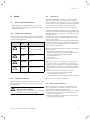
1.4
Applicability of the instructions
These installation instructions apply only to appliances
with the following article numbers:
Type designation
Article number
Countries
VRC 470f
0020108137
GB, IE
Tab. 1.1
Type designations and article numbers
The 10-digit article number can be found in the serial
number of your appliance.
The serial number is displayed when you press the left
function key under "Information/Serial number". It is in
the second line of the display (¬ Operating instructions).
1.5
CE label
> Pass these installation instructions and all other applicable documents and, if necessary, any required tools
to the system operator.
The system operator should retain those instructions
and tools so that they are available when required.
CE labelling shows that, based on the type overview, the
appliances comply with the basic requirements of the
following directives:
– Electromagnetic compatibility directive (Council Directive 2004/108/EC)
– Low voltage directive (Council Directive 2006/95/EC).
– Directive on radio and telecommunications terminal
equipment (R&TTE Directive 1999/5/EC)
– Directive on electromagnetic compatibility and radio
spectrum matters (Directive ETSI EN 300220-2)
1.3
1.6
1.2
Document storage
Symbols used
The symbols used in the text are explained below: Symbols for identifying dangers are also used in these operating instructions (¬ Section 2.1.1).
i
>
4
Glossary
Technical terms are explained in the Glossary (¬ Section 15) at the end of these operating instructions.
Symbol that denotes useful tips and
information
Symbol for a required action
Installation instructions VRC 470f 0020124645_00
Safety 2
2
Safety
2.1
2.2
Safety and warning information
> When installing the VRC 470f, take account of the
basic safety instructions and the warnings that may
appear before an action.
2.1.1
Classification of warnings
The warning notes are classified in accordance with the
severity of the possible danger using the following danger signs and signal words:
Danger sign
a
e
a
b
Signal
word
Danger!
Explanation
Immediate risk of death
or
risk of severe personal
injury
Danger!
Risk of death from electric shock
Warning!
Risk of minor personal
injury
Caution!
Risk of material or environmental damage
Tab. 2.1 Meaning of danger signs and signal words
2.1.2
Structure of warnings
Warning signs are identified by an upper and lower separating line and are laid out according to the following
basic principle:
a
Signal word!
Type and source of danger!
Explanation of the type and source of danger.
> Measures for averting the danger.
Installation instructions VRC 470f 0020124645_00
Intended use
The Vaillant VRC 470f controller is a state-of-the-art
appliance constructed in accordance with recognised
safety regulations. Nevertheless, there is a risk of death
or serious injury to the operator or others or of damage
to the appliances and other property in the event of
improper use or use for which they are not intended.
The Vaillant VRC 470f controller controls a heating system based on outside temperature and programmed timings. The controller is connected to a Vaillant boiler with
an eBUS interface.
The controller can also control the supply of domestic
hot water from a connected DHW cylinder with or without secondary return.
You should only remove the controller temporarily from
the wall-mounting base, e.g. to adjust the settings. Apart
from that, you should always operate it in conjunction
with the wall-mounting base.
Operation is permissible with the following components
and accessories:
– Domestic hot water cylinder (conventional)
– Vaillant stratified charge cylinder actoSTOR VIH RL
– Circulation pump for the hot water supply
– Second heating circuit
– Solar system
– Remote control unit
Any other use, or use beyond that specified, shall be
considered as improper use. Any direct commercial or
industrial use is also deemed to be improper. The manufacturer/supplier is not liable for any damage resulting
from improper use. In this case, the user alone bears the
liability.
It is also considered as intended use to observe:
– the operating and installation instructions
– all other applicable documents
– compliance with the care and maintenance conditions.
Improper use of any kind is prohibited!
2.3
Basic safety instructions
The device must be installed by a competent person,
who is responsible for compliance with the applicable
requirements, regulations and directives.
> Read through these installation instructions carefully.
> Carry out the activities that are described in these
installation instructions.
> During the installation, observe the following safety
instructions and regulations.
5
2 Safety
Protecting against legionella
The controller is furnished with an anti-legionella function to protect against infection by germs (legionella).
When the function is activated, the water in the domestic hot water cylinder is heated to over 60 °C for at least
one hour.
> Set the anti-legionella function when installing the
controller.
> Explain to the operator how the anti-legionella function works.
Preventing the risk of scalding
There is a danger of scalding at the hot water draw-off
points if the temperatures are greater than 60 °C. Young
children and elderly persons are particularly at risk from
scalding at lower temperatures.
> Select a moderate target temperature.
> Inform the owner about the risk of scalding when the
anti-legionella function is switched on.
2.4
Requirements for cables
> Use standard commercial cables for wiring.
Minimum cross-section of the cable:
– Supply cable 230 V (pumps or mixer supply cable):
1.5 mm2
– Low-voltage conductors(sensor or bus lines):
0.75 mm2
Maximum cable length:
– Sensor lines: 50 m
– Bus lines: 300m
> At lengths of over 10 m, 230V supply cables must be
laid separately from sensor or bus lines.
> Fasten the supply cables using the strain relief device
in the wall mount.
> Do not use the free terminals in the appliance as supports for other wiring.
> The controller should only be installed in dry rooms.
Protecting the controller from damage
> The controller should only be installed in dry rooms.
2.5
Preventing malfunction
> Ensure that the heating system is in a technically perfect condition.
> Ensure that no safety or monitoring devices have
been removed, bridged or disabled.
> Immediately rectify any faults and damage that may
affect safety.
> Inform the operator that he must not cover the controller with furniture, curtains or other objects.
> If thermostatic control is activated, advise the operator that, in the room where the controller is mounted,
all the radiator valves must be fully open.
6
Directives, laws and standards
> All wiring must be in accordance with Building Regulations Part P and BS 7671 (IEE Wiring Regulations), and
must be carried out by a suitably qualified person.
Installation instructions VRC 470f 0020124645_00
System description 3
3
System description
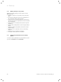
3.1
3.2
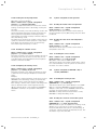
System design
The VRC 470f controller controls the Vaillant heating
and hot water systems.
You can fix the controller to a wall using the wall-mounting base.
You can mount the radio receiver unit on a wall using
the wall-mounting base or in the controller slot of a Vaillant boiler, without the wall-mounting base.
1
2
3
4
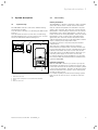
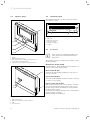
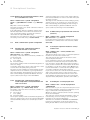
Fig. 3.1
1
2
3
4
System drawing
VRC 470f controller
VR 21 outside temperature sensor/transmitter (DCF77)
Boiler
Radio receiver unit
Installation instructions VRC 470f 0020124645_00
Functionality
Heating installation
The VRC 470f is a weather compensator with a separate
sensor. The VR 21 sensor is fitted outdoors and measures the outside temperature and transmits it by radio
signal to the controller. The controller controls the flow
temperature of the heating as a function of the outside
temperature. If the outside temperature is low, the controller increases the flow temperature, and if the outside
temperature is high, it reduces the flow temperature
again. Thus, the controller absorbs fluctuations in the
outside temperature and the room temperature remains
at the constant, preset temperature value.
Hot water production is not affected by the weather
compensation.
The controller is supplied with power by batteries.
Data transmission between the controller and the radio
receiver unit takes place via radio communication. Data
transmission between the radio receiver unit and the
boiler takes place via an eBUS interface, which also provides the power supply for the radio receiver unit.
For remote diagnosis and programming, you can equip
the controller with the Vaillant Internet communication
system vrnetDIALOG.
Hot water production
With the VRT 470f controller you can also specify the
temperature and timings for hot water production. The
boiler heats the water in the domestic hot water cylinder
to the preset temperature. The times at which hot water
should be available in the cylinder, can be defined with
the help of time periods.
If a circulation pump is installed in the heating system,
time periods can also be set for circulation of the hot
water.
7
3 System description
3.3
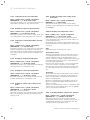
Appliance design
3.4
Identification plate
The identification plate is located on the rear panel of
the controller casing.
21110700201081340082005003N2
9 . . . 24V <50mA
1
VRC 470f
1
Fig. 3.4
1
2
3
4
5
5
4
3
2
3
4
5
Identification plate (example)
EAN code
Appliance designation
Operating voltage
Current consumption
CE label
3.5
Accessories
2
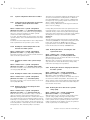
Fig. 3.2
1
2
3
4
5
i
Front view of VRC 470f radio controller
Display
Wall-mounting base cover
Right function key for "Mode" (soft key function)
Control knob (no button function)
Left function key for "Menu" (soft key function)
If the controller is supplemented with accessories, please note all relevant installation
instructions.
The following accessories can be used to expand controller functionalities:
Multi-function module VR 40
The multi-function model VR 40 can be used by the controller to control a circulation pump.
1
Mixer module VR 61/2
The mixer module VR 61/2 expands the controller to a
2-circuit controller.
Solar module VR 68/2
The solar module VR 68/2 can be used by the controller
to control a solar system.
4
2
3
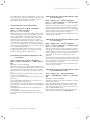
Fig. 3.3
1
2
3
4
8
Remote control unit VR 81/2
If the second heating circuit is to be satellite controlled,
you can use the VR 81/2 remote control unit. You can
use the remote control unit VR 81/2 to set the parameter "Room temp. target".
In addition, the controller displays service and fault messages by means of symbols.
Data interchange is via eBus line.
Front view of radio receiver unit
Wall-mounting base
Diagnosis socket for the heating engineer
LED
Teach-in button
Installation instructions VRC 470f 0020124645_00
Installation 4
4
Installation
You can either integrate the radio receiver unit in the
boiler or install it separately on a wall. If you are wallmounting the radio receiver unit, you connect it to the
boiler via a 2-core eBUS cable.
You can fix the controller to a wall in the living area.
4.1
Checking the delivery
Quantity Component
1
VRC 470f controller
1
Radio receiver unit
1
VR 21 outside temperature sensor/transmitter
1
Wall-mounting base for radio receiver unit
1
Wall-mounting base for VRC 470f
2
Fastening material (2 screws and 2 wall plugs)
1
Battery set (4 x AA)
1
3-pin pin header connector
1
Operating instructions
1
Installation instructions
Tab. 4.1 Scope of delivery
4.2
Requirements for the installation site
4.2.1
Radio receiver unit
4.2.3
Outside temperature sensor/transmitter
The installation site of the outside temperature sensor/
transmitter should be:
– not fully protected from wind
– not particularly draughty
– not in direct sunlight
– not affected by heat sources
– on a north or north-west facing wall
– easily accessible so that the solar cell can easily be
cleaned
– a short distance from the radio receiver unit
> During start-up, check whether radio communication
between the outside temperature sensor/transmitter
and the radio receiver unit can be established.
> If radio communication is adversely affected by electrical equipment or buildings, then choose a different
installation site for the outside temperature sensor/
transmitter.
4.3
Fitting the radio receiver unit in the boiler
e
Danger!
Risk of death from live connections!
When working in the control cabinet of the
boiler there is a risk of death from electric
shock. Continuous voltage is present on the
mains connection terminals, even if the main
switch is turned off!
> Switch the main switch off before working
on the control cabinet of the boiler.
> Disconnect the boiler from the mains
power by disconnecting the mains plug or
by de-energising the boiler via an isolating
device with a contact opening of at least
3 mm (e. g. fuses or power switches).
> Secure the power supply against being
switched on again.
> Open the control cabinet only when the
appliance is disconnected from the power
source.
i
When fitting the radio receiver unit in the
boiler's switch box, follow the instructions for
fitting a controller given in the boiler installation instructions.
> Install the radio receiver unit in the boiler.
> If radio communication cannot be established when
the radio receiver unit is installed in the boiler, then
install it in a suitable position on a wall.
4.2.2 Controller
> Position the controller so that proper detection of the
room temperature is possible; e.g. on an internal wall
of the main living room, at a height of approx. 1.5 m
> If room temperature control is activated, advise the
operator that, in the room where the controller is
mounted, all the radiator valves must be fully open.
Install the radio receiver unit in the boiler as follows:
> Switch off the boiler.
> Ensure that the boiler is disconnected from the power
source.
Installation instructions VRC 470f 0020124645_00
9
4 Installation
> If necessary, open the front cover on the boiler.
> Carefully lever the blind cover from the control cabinet.
> Carefully lever the radio receiver unit from the wallmounting base (¬ Section 4.4.1).
> Check which type of switch box the boiler has:.
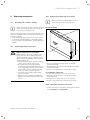
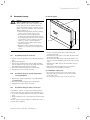
4.4
Wall-mounting the radio receiver unit
i
Wall-mounting the radio receiver unit is only
necessary if its position needs to be optimised
after start-up in order to ensure good radio
communication with the controller and the
outside temperature sensor/transmitter.
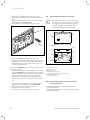
1
1
7
6
2
2
4
3
5
Fig. 4.1
Plugging in/removing pin header connector
3
3
If there are vertical plug connections with pins:
> If the 3-pin pin header connector (2) is pre-fitted on
the PCB (1) of the radio receiver unit, then remove it.
> Carefully press the radio receiver unit into the connection in the switch box.
If there are horizontal plug connections without pins on
the control cabinet:
> If the 3-pin pin header connector (2) is not pre-fitted,
plug the short pins of the 3-pin pin header connector
supplied with the controller into the horizontal row of
3 holes on the PCB (1) of the radio receiver unit.
> Carefully press the radio receiver unit with the pin
header connector into the connection in the switch
box.
4
Fig. 4.2 Mounting the radio receiver unit
1
2
3
4
5
6
7
Radio receiver unit
Wall-mounting base
Mounting holes
Openings for cable entry
Pin header with terminals for the eBUS cable
Wall-mounting base cover
Slot for screwdriver
4.4.1
> If you have not already done so, install the outside
temperature sensor/transmitter (¬ Section 4.5).
> Switch on the power supply to the boiler.
> Bring the boiler into operation.
> If necessary, close the front cover of the boiler.
10
Removing the radio receiver unit from the
wall-mounting base
> Insert a screwdriver into the slot (7) on the wallmounting base (2).
> Carefully lever the radio receiver unit (1) off the wallmounting base (2).
Installation instructions VRC 470f 0020124645_00
Installation 4
4.4.2
Secure the wall-mounting base to the wall
> Mark the position on the wall. Take the eBUS line
route into account when doing so.
> Drill two holes of 6 mm diameter in accordance with
the mounting holes (3).
> Insert the wall plugs supplied.
> Insert the eBUS cable through one of the cable opening (4).
> Use the screws supplied to secure the wall-mounting
base.
> Connect the eBUS cable to the terminals of the pin
header (¬ Section 5).
4.4.3
Fitting the radio receiver unit
> Carefully insert the radio receiver unit in the wallmounting base. Take care to ensure that the pin
header connector (5) on the wall-mounting base fits
in the connection provided on the radio receiver unit.
> Carefully press the radio receiver unit into the wallmounting base until the catches on the controller
audibly click into the sides of the wall-mounting base.
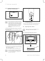
4.5
Fitting the outside temperature sensor/
transmitter
b
Caution!
Risk of material damage if fitted incorrectly!
Incorrect fitting can cause damage to the
device, e.g. caused by damp.
> Take care to fit the outside temperature
sensor/transmitter the right way up.
i
i
The outside temperature sensor/transmitter is
supplied with power by a solar cell. Therefore,
there is no need for battery replacement.
The outside temperature sensor/transmitter
should not be exposed to direct sunlight.
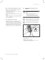
Fig. 4.3 Removing the wall-mounting base
Proceed as follows:
> Mark the position on the wall.
> Remove the wall-mounting base from the outside
temperature sensor/transmitter.
Installation instructions VRC 470f 0020124645_00
11
4 Installation
1
2
Fig. 4.4 Fitting the wall-mounting base
> Drill two holes of 6 mm diameter matching the positions of the fixing holes.
> Insert the wall plugs supplied.
> Fix the wall-mounting base to the wall using two
screws (1, 2).
Fig. 4.6 Attaching the outside temperature sensor/transmitter
> Slide the outside temperature sensor/transmitter onto
the wall-mounting base until it clicks into position.
1
2
Fig. 4.5 Starting up the outside temperature sensor/transmitter
1 LED
2 Button
> Activate the outside temperature sensor/transmitter
by pressing the red button (2) on the back of the unit
with a pointed implement.
The green LED (1) will flash for about 30 seconds.
i
12
Be certain to start up the outside temperature
sensor/transmitter as otherwise no data (e.g.
outside temperature) will be transmitted to
the radio receiver unit.
Installation instructions VRC 470f 0020124645_00
Installation 4
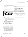
4.6
Fitting the controller
> Before mounting the controller on the wall, check
whether radio communication between the controller
and the radio receiver unit can be established (¬ Section 8.7).
> If radio communication is adversely affected by electrical equipment or buildings, then choose a different
installation site for the controller or the radio receiver
unit.
Fig. 4.8 Battery polarity
1
2
3
Fig. 4.7
Fitting the wall-mounting base
> Open the battery compartment on the underside of
the controller.
> Remove the two plastic strips between the batteries
and the contacts.
i
Make sure battery polarity is the right way
round (¬ Fig. 4.8).
Depending on usage, the batteries should last
approx. 1 to 1.5 years.
> Close the battery compartment.
> Hook the controller onto the wall-mounting base.
> Press the controller down onto the wall-mounting
base until it audibly clicks into position.
> Check the quality of radio communication (¬ Section 8.7).
1 Wall-mounting base
2 Mounting holes
3 Wall-mounting base finishing panel
Proceed as follows:
> Remove the wall-mounting base from the rear of the
controller by pulling the base downwards.
> Remove the finishing panel from the wall-mounting
base by pulling the top edge of the panel away from
the wall-mounting base with your fingers.
> Mark the position on the wall.
> Drill two holes of 6 mm diameter matching the positions of the fixing holes (2).
> Insert the wall plugs supplied.
> Fix the wall-mounting base (1) to the wall using the
screws supplied.
> Locate the two bottom lugs of the finishing panel (3)
in the holes in the wall-mounting base.
> Press the top edge of the finishing panel into the wallmounting base until it clicks into position.
Installation instructions VRC 470f 0020124645_00
13
5 Electrical installation
5
Electrical installation
e
Danger!
Risk of death from live connections!
When working in the control cabinet of the
boiler there is a risk of death from electric
shock. Continuous voltage is present on the
mains connection terminals, even if the main
switch is turned off!
> Switch the main switch off before working
on the control cabinet of the boiler.
> Disconnect the boiler from the mains
power by disconnecting the mains plug or
by de-energising the boiler via an isolating
device with a contact opening of at least
3 mm (e. g. fuses or power switches).
> Secure the power supply against being
switched on again.
> Open the control cabinet only when the
appliance is disconnected from the power
source.
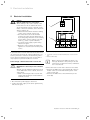
1
2
Fig. 5.1
If you fit the radio receiver unit in the boiler, the electrical connections are made by contact between the controller's pin header connector and the mating connection on the boiler. Wiring up the radio receiver unit is
only required if you have mounted it on a wall.
Connecting up a wall-mounted radio receiver unit
b
Caution!
Malfunctions caused by incorrect installation!
Without a bridge between terminals 3 and 4
on the PCB in the control cabinet, the boiler
cannot work.
> When connecting the radio receiver unit,
ensure that the jumper is fitted between
terminals 3 and 4.
Wiring up the radio receiver unit
1
Pin header connector in wall-mounting base of radio receiver
unit
2 Boiler terminal strip
i
When connecting the eBUS line, there is no
need pay attention to the polarity. If the two
connections are switched around, communication is not affected.
Connect the radio receiver unit to the boiler as follows:
> Connect the eBUS line to the terminals (1) of the pin
header connector in the wall-mounting base of the
radio receiver unit.
> Connect the eBUS line to the terminal strip of the
boiler (2).
> Disconnect the power supply to the boiler.
> Secure the power supply to the boiler against being
switched on again.
14
Installation instructions VRC 470f 0020124645_00
Start-up 6
6
Start-up
When you start the controller for the first time after
electrical installation or after replacement, the Installation assistant starts automatically. The installation
assistant helps you to enter the most important settings
for the heating system.
The operating concept, an example of operation and the
menu structure are described in the operating instructions of the controller (¬ Operating instructions).
All settings that you have made via the Installation
assistant can be changed again at a later date via the
"Installer level" menu.
The reading and setting options of the Installer level are
described in (¬ Section 7) and (¬ Section 8).
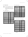
6.1
Overview of Installation assistant set-up
options
Setting
Values
Unit
Step size, select
Factory
reset
–
Languages available for selection
German
Heating circuit 1 3)
Generator circuit, inactive
Generator
circuit
Heating circuit 2 3)
Zone, mixing circuit, inactive
Mixing
circuit
LP/ZP relay connection 3)
Cylinder charge pump, circulation pump,
not connected
Not connected
0.5
17.5
Multi relay 1)
Difference control, 2nd cylinder
Difference
control
Solar pump kick 1)
OFF, ON
Off
1
130
Country of installation 2)
Country available for selection
Germany
Heating circuit conf.3)
HEATING 1, HEATING 2,
HEATING 1 & HEATING 2
HEATING 1
Low loss header 4)
On, Off
Off
Cylinder
Active, Inactive
Active
Language
Solar flow volume 1)
Solar circuit protection 1)
Tab. 6.1
1)
2)
3)
4)
min.
max.
–
–
0.0
Off, 110
99.5
150
l/min
°C
Own
setting
Overview of Installation assistant set-up options
Appears only if solar module VR 68/2 is connected.
Appears only if solar station VMS is connected.
Appears only if mixing module VR 61/2 is connected.
Appears only if cylinder actoSTOR VIH RL is connected.
Installation instructions VRC 470f 0020124645_00
15
6 Start-up
6.2
Making settings for the operator
Make the following settings for the operator via the
Operating level:
> If DCF77 reception is not possible, set the date and
time.
> If necessary, change the factory-set designations of
the components in the heating system.
> Set the mode for the heating function. The mode for
hot water production is dependent on this and cannot
be set separately.
> Set the target room temperature ("Desired day temperature").
> Set the set-back temperature ("Desired night temperature").
> Set the hot water temperature ("Desired hot water
temperature").
> Set the period for automatic mode of the heating
function.
> Set the period for hot water production.
> If relevant, set the period for circulation.
6.3
Setting other parameters for the heating
system
You can set other parameters via the "Installer" operating level, (¬ Section 7) and (¬ Section 8).
16
Installation instructions VRC 470f 0020124645_00
Operation 7
7
Operation
The menu structure, the operating concept and an
example of operation are described in the operating
instructions of the controller (¬ Operating instructions).
The controller has two operating levels, the Operator
level and the Installer level.
The options for reading information and entering settings on the Operator level are also described in the
operating instructions.
Below, you can find the reading and set-up options which
can be accessed via the left function key "Menu" and list
entry "Installer level".
i
Several consecutive displays indicate possible
additional heating circuits. Menu entries
shown in grey are only available if a corresponding expansion module is connected.
Installation instructions VRC 470f 0020124645_00
17
7 Operation
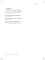
7.1
Overview of menu structure
Menu
Day at home scheduling
Basic settings
Installer level
Back
Select
Installer level
Service information
System configuration
Sensor/ actuator test
Enter code
000
Back
Ok
Back
Service information
Enter contact details
Service date
Select
Back
Select
Service information
Enter contact details
Service date
Back
Installer level
Service information
System configuration
Sensor/ actuator test
Back
System
Status
Water pressure
Domestic hot water
Select
Select
HEATING 1
Set-back temp.
Flow temp. target
Flow temp. current
OK
2,3bar
Charged
Back
System
Collector temp
Frost protect. delay
Pump Blocking Time
HEATING 1
Pump status
Room temp control
Summer mode offset
76°C
4h
15 min
Back
System
Max. pre-heat
Max. pre-switch-off
OT constant heating
Back
System
Raising temperature
Control modules
Heating circuit conf.
Back
0 min
0 min
Off
Change
0K
List
Ht crt. 1
Change
Back
Heat Generator
Off
Low loss header
HEATING 1-----------------------------------Circuit type
Active
HEATING 1
Auto day temp until
Room temp. target
Room temp. currant
Back
Back
Change
Change
22:10
20,0°C
20,0°C
Back
Back
18
Off
None
1K
1,2
15°C
Eco
Change
Change
HEATING 1
None
Advanced functions
HEATING 2
2----------------------------------Active
Circuit type
Back
Back
Domestic hot water
Domestic hot water----------------------Active
Cylinder
Cylinder temp. target.
60°C
Back
Domestic hot water
Cyl. temp. current
Cylinder charge pump
Circulation pump
59°C
Off
Off
Back
Domestic hot water
Anti-legionella day
Anti-legionella time
Cylinder boost offset
Back
Domestic hot water
Load pump
Paral. cyl. charge
LP/ZP relay connection
Back
Fig. 7.1
Change
Change
Back
Back
HEATING 1
Heat curve
Min. temperature
System off mode
Heat Generator
Heat Generator---------------------------Off
Status
40°C
VF1
Back
Back
Back
Back
15,0°C
0°C
22°C
Off
4:00
25K
Change
5 min
Off
no connect.
Change
Installer level menu structure Part 1
Installation instructions VRC 470f 0020124645_00
Operation 7
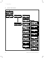
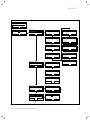
Menu
Day at home scheduling
Basic settings
Installer level
Back
Select
Enter code
Installer level
Service information
System configuration
Sensor/ actuator test
000
Back
Ok
Back
Solar
Solar-----------------------------------------20°C
Sensor cylinder 2
10°C
Sensor solar gain
Select
Back
Back
Solar
Status solar pump
Sensor TD1
Sensor TD2
On
64°C
54°C
Solar
Status multi relay
Solar pump runtime
Reset solar runtime
On
1963h
No
Solar
Pump control
Lead cylinder
Solar flow voume
Off
1
165l/min
VR 61
Actuator
Sensor
LP/ZP
VF2
65°C
Back
Back
Fig. 7.2
Select
10
10
Off
Back
ZP
T1
55°C
Back
Installer level
Screed drying function
Change code
-------------------------------------------------
RF connection
Control
Outside temp. sensor
Teach-in
Select
actoSTOR
Actuator
Sensor
Select
2nd Difference control
2nd Difference control-------------------7K
On temp. diff.
3K
Off temp. diff.
MA
KOL1
76°C
Back
Back
Change
Change
Select
VR 68
Actuator
Sensor
Installer level
Screed drying function
Change code
-------------------------------------------------
Solar cylinder 1
3K
Off temp. diff.
Solar cylinder 2---------------------------65°C
Max. temperature
Back
Back
Select
Change
Solar cylinder 1
Solar cylinder 1---------------------------65°C
Max. temperature
7K
On temp. diff.
Back
Back
Back
Back
diff. ctrl
Off
130°C
Back
Back
Back
Installer level
Service information
System configuration
Sensor/ actuator test
Solar
Multi relay
Solar pump kick
Solar circuit prot.
Select
Screed drying function
HEATING 1
Day
Temperature
Back
Back
00
0,0°C
Change
Change
Change code
New code
000
Back
Change
Installer level menu structure Part 2
Installation instructions VRC 470f 0020124645_00
19
7 Operation
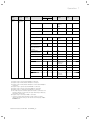
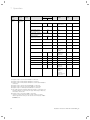
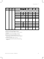
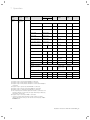
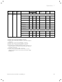
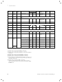
7.2
Overview of Installer level
Selection
level 1
Selection
level 2
Selection
level 3
Installer
level
Service
information
Enter
contact
details
Service
date
System
configuration
Setting level
Values
Step size,
select
Factory
reset
000
min.
max.
Enter code
000
999
–
1
Installer
1
11
Figures
A to Z,
0 to 9,
blank spaces
Phone
1
12
Numbers
0 to 9,
blank spaces,
hyphen
Next service on
Date
Own setting
01.01.11
System
Status
Current value*
–
Water pressure
Current value
bar
Domestic hot water
Current value
°C
Collector temp 1)
Current value
°C
Frost protect. delay
0
12
h
1
4
Pump Blocking Time
Off, 5
60
min
1
15
Max. pre-heat
0
300
min
10
0
Max. pre-switch-off
0
120
min
10
0
OT constant heating
Off, -25
10
°C
1
Off
Raising temperature 2)
0
15
K
Control modules
List
Heating circuit
conf. 2)
Tab. 7.1
Unit
0
Software version
Ht crt. 1, Ht
crt. 2,
Ht crt. 1&2
Ht crt. 1
Overview of Installer level
1) Appears only if solar module VR 68/2 is connected.
2) Appears only if mixing module VR 61/2 is connected.
3) Appears only if mixing module VR 61/2 or solar module VR 68/2 is
connected.
4) Appears only if cylinder actoSTOR VIH RL is connected.
5) Appears only if remote control unit VR 81/2 is connected.
6) Appears only if no mixing module VR 61/2 is connected.
7) This figure depends on which expansion module is connected. If no
expansion module is connected, the upper limit may be limited by
the setting on the boiler.
8) Appears only if solar station VMS is connected.
* If there is no fault, then the status is "OK". If there is a fault,
"Fault" appears here and you can read the error message (¬ Section 10.2) here.
20
Installation instructions VRC 470f 0020124645_00
Operation 7
Selection
level 1
Selection
level 2
Installer
level
System
configuration
Selection
level 3
Setting level
Values
min.
Unit
max.
Step size,
select
Factory
reset
Own setting
Heat generator
Status
Current value
Off,
Heating,
DHW
VF1
Current value
Low loss header 4)
Current value
On, Off
Off
Circuit type 2)
Inactive
Inactive,
Active
Active
Auto day temp until
Current value
h:min
Room temp. target
(Day temperature)
5
30
°C
0.5
20
Room temp. currant 5) (Room temperature)
Current value
°C
Set-back temp.
(Night temperature)
5
30
°C
0.5
15
Flow temp. target
Current value
°C
Flow temp. current
Current value
°C
HEATING 1
Pump status
2)
Active
Current value
On, Off
Room temp control
Summer mode offset
-3
30
Heat curve
0.20
4.0
Min. temperature
15
90
System off mode
Advanced functions
Tab. 7.1
Current value
K
°C
None,
Modulation,
Thermost.
None
1
1
0.05
1.2
1
15
Eco,
Set-back,
Frost prot.
Eco
None
Overview of Installer level
1) Appears only if solar module VR 68/2 is connected.
2) Appears only if mixing module VR 61/2 is connected.
3) Appears only if mixing module VR 61/2 or solar module VR 68/2 is
connected.
4) Appears only if cylinder actoSTOR VIH RL is connected.
5) Appears only if remote control unit VR 81/2 is connected.
6) Appears only if no mixing module VR 61/2 is connected.
7) This figure depends on which expansion module is connected. If no
expansion module is connected, the upper limit may be limited by
the setting on the boiler.
8) Appears only if solar station VMS is connected.
* If there is no fault, then the status is "OK". If there is a fault,
"Fault" appears here and you can read the error message (¬ Section 10.2) here.
Installation instructions VRC 470f 0020124645_00
21
7 Operation
Selection
level 1
Selection
level 2
Installer
level
System
configuration
Selection
level 3
Setting level
Values
Unit
Factory
reset
Inactive,
Active, Zone
Active
0.5
20
0.5
15
max.
Circuit type
Inactive
Active
Auto day temp until
Current value
hr:min
Room temp. target
(Day temperature)
5
30
°C
Room temp. currant
(Room temperature)
Current value
°C
Set-back temp.
(Night temperature)
5
30
°C
Flow temp. target
Current value
°C
Flow temp. current
Current value
°C
Pump status
Current value
On, Off
Mixer status
Current value
Opening,
Stationary,
Closing
Own setting
HEATING 2 2)
Room temp control
Summer mode offset
-3
30
None,
Modulation,
Thermost.
None
K
1
1
Heat curve
0.20
4.0
0.05
1.2
Min. temperature
15
90
°C
1
15
Max. temperature
15
90
°C
1
75
Eco,
Set-back,
Frost prot.
Frost prot.
None,
Away from
home,
At home,
Party function,
Cyl. boost
None
System off mode
Advanced functions
Tab. 7.1
Step size,
select
min.
Current value
Overview of Installer level
1) Appears only if solar module VR 68/2 is connected.
2) Appears only if mixing module VR 61/2 is connected.
3) Appears only if mixing module VR 61/2 or solar module VR 68/2 is
connected.
4) Appears only if cylinder actoSTOR VIH RL is connected.
5) Appears only if remote control unit VR 81/2 is connected.
6) Appears only if no mixing module VR 61/2 is connected.
7) This figure depends on which expansion module is connected. If no
expansion module is connected, the upper limit may be limited by
the setting on the boiler.
8) Appears only if solar station VMS is connected.
* If there is no fault, then the status is "OK". If there is a fault,
"Fault" appears here and you can read the error message (¬ Section 10.2) here.
22
Installation instructions VRC 470f 0020124645_00
Operation 7
Selection
level 1
Selection
level 2
Installer
level
System
configuration
Selection
level 3
Setting level
Values
Unit
min.
max.
Cylinder
Inactive
Active
Cylinder temp.
target.
35 7)
70
Cyl. temp. current
Current value
Cylinder charge
pump
Current value
Circulation pump
Current value
Factory
reset
Active,
Inactive
Active
1
60
Own setting
Domestic hot water
°C
°C
On, Off
On, Off
Anti-legionella day
Mon, Tue, Wed,
Thu, Fri, Sat,
Sun,
Off,
Mon-Sun
Off
Anti-legionella time
0:00
23:50
hr:min
10 min
4:00
Cylinder boost
offset 3)
15
40
K
1
25
Load pump 3)
0
10
min
1
5
Paral. cyl. charge 2)
Off
On
Off, On
Off
no connect.,
Circ. pump,
Charg.pump
no connect.
LP/ZP relay connection 2)
Tab. 7.1
Step size,
select
Overview of Installer level
1) Appears only if solar module VR 68/2 is connected.
2) Appears only if mixing module VR 61/2 is connected.
3) Appears only if mixing module VR 61/2 or solar module VR 68/2 is
connected.
4) Appears only if cylinder actoSTOR VIH RL is connected.
5) Appears only if remote control unit VR 81/2 is connected.
6) Appears only if no mixing module VR 61/2 is connected.
7) This figure depends on which expansion module is connected. If no
expansion module is connected, the upper limit may be limited by
the setting on the boiler.
8) Appears only if solar station VMS is connected.
* If there is no fault, then the status is "OK". If there is a fault,
"Fault" appears here and you can read the error message (¬ Section 10.2) here.
Installation instructions VRC 470f 0020124645_00
23
7 Operation
Selection
level 1
Selection
level 2
Installer
level
System
configuration
Selection
level 3
Setting level
Values
min.
Unit
max.
Step size,
select
Factory
reset
Own setting
Solar 1)
Cylinder sensor 2
Current value
°C
Sensor solar gain
Current value
°C
Status solar pump
Current value
Sensor TD1
Current value
°C
Sensor TD2
Current value
°C
Status multi relay
Current value
Solar pump runtime
Current value
Reset solar runtime
No
Yes
No, Yes
No
Pump control
Current value
Off, On
Off
Lead cylinder
1
2
1, 2
1
Solar flow voume
0.0
99.0
0.5
3.5
diff. ctrl,
Cylinder2
diff. ctrl
On, Off
Off
1
130
Country available for selection
Germany
On, Off
On, Off
h
l/min
Multi relay
Solar pump kick
On
Off
Solar circuit prot.
Off, 110
150
°C
VMS 8)
Country of installation
Solar cylinder 1 1)
Tab. 7.1
Max. temperature
20
90
°C
1
65
On temp. diff.
2
25
K
1
7
Off temp. diff.
1
20
K
1
3
Overview of Installer level
1) Appears only if solar module VR 68/2 is connected.
2) Appears only if mixing module VR 61/2 is connected.
3) Appears only if mixing module VR 61/2 or solar module VR 68/2 is
connected.
4) Appears only if cylinder actoSTOR VIH RL is connected.
5) Appears only if remote control unit VR 81/2 is connected.
6) Appears only if no mixing module VR 61/2 is connected.
7) This figure depends on which expansion module is connected. If no
expansion module is connected, the upper limit may be limited by
the setting on the boiler.
8) Appears only if solar station VMS is connected.
* If there is no fault, then the status is "OK". If there is a fault,
"Fault" appears here and you can read the error message (¬ Section 10.2) here.
24
Installation instructions VRC 470f 0020124645_00
Operation 7
Selection
level 1
Selection
level 2
Installer
level
System
configuration
Selection
level 3
Setting level
Values
Unit
Step size,
select
Factory
reset
90
°C
1
65
2
25
K
1
7
1
20
K
1
3
On temp. diff.
2
25
K
1
7
Off temp. diff.
1
20
K
1
3
Control
0
10
1
Outside temp.
sensor
0
10
1
Teach-in
On
Off
On, Off
min.
max.
Max. temperature
20
On temp. diff.
Off temp. diff.
Own setting
Solar cylinder 21)
2nd Difference control
RF connection
Tab. 7.1
Off
Overview of Installer level
1) Appears only if solar module VR 68/2 is connected.
2) Appears only if mixing module VR 61/2 is connected.
3) Appears only if mixing module VR 61/2 or solar module VR 68/2 is
connected.
4) Appears only if cylinder actoSTOR VIH RL is connected.
5) Appears only if remote control unit VR 81/2 is connected.
6) Appears only if no mixing module VR 61/2 is connected.
7) This figure depends on which expansion module is connected. If no
expansion module is connected, the upper limit may be limited by
the setting on the boiler.
8) Appears only if solar station VMS is connected.
* If there is no fault, then the status is "OK". If there is a fault,
"Fault" appears here and you can read the error message (¬ Section 10.2) here.
Installation instructions VRC 470f 0020124645_00
25
7 Operation
Selection
level 1
Selection
level 2
Selection
level 3
Sensor/
actuator
test
Setting level
Select module
Values
min.
max.
–
–
Unit
Step size,
select
–
Connected
expansion
modules
–
LP/ZP, HK1-P,
HK2 AUF, HK2
ZU, HK2-P
Factory
reset
Own setting
VR 61 2)
Actuator
Sensor
VF2
VF2
VR 68 1)
Actuator
–
–
–
MA, KOL1-P,
LEG-P
Sensor
KOL1, SP1, SP2,
Yield, TD1, TD2
actoSTOR 4)
Actuator
–
–
–
ZP, P1, P2, AL
Sensor
Installer
level
Screed
drying
function
Change
code
Tab. 7.1
T1, T2, T3, T4,
Anode
HEATING 1 Day 6)
00
29
Day
Temperature 6)
Curr.
value
45
°C
HEATING 2 Day 2)
00
29
Day
Temperature
Curr.
value
45
°C
New code
000
999
1
00
1
00
1
000
Overview of Installer level
1) Appears only if solar module VR 68/2 is connected.
2) Appears only if mixing module VR 61/2 is connected.
3) Appears only if mixing module VR 61/2 or solar module VR 68/2 is
connected.
4) Appears only if cylinder actoSTOR VIH RL is connected.
5) Appears only if remote control unit VR 81/2 is connected.
6) Appears only if no mixing module VR 61/2 is connected.
7) This figure depends on which expansion module is connected. If no
expansion module is connected, the upper limit may be limited by
the setting on the boiler.
8) Appears only if solar station VMS is connected.
* If there is no fault, then the status is "OK". If there is a fault,
"Fault" appears here and you can read the error message (¬ Section 10.2) here.
26
Installation instructions VRC 470f 0020124645_00
Description of functions 8
8
Description of functions
The list entry "Installer level" in selection level 1 of the
menu structure has five sub-entries with further selection levels:
– Service information
– System configuration
– Sensor/ actuator test
– Screed drying function
– Change code
Functions with read-out options and functions with setup options are grouped together here.
The list of the second selection level "System configuration" is structured by components of the heating system:
– System
– Heat generator
– HEATING 1
– Domestic hot water
– Radio communication
The message is switched off if:
– the date is in the future.
– the initial date 01.01.2011 is set.
8.2
System configuration: System
8.2.1
Reading the system status
Menu ¬ Installer level ¬ System configuration
[System ----] ¬ Status
This function allows you to read the status of the heating system. If there is no fault, the message "OK"
appears here. If there is a fault, the status "Fault" is displayed. If you press the right function key, the list of
error messages will be displayed.
Error messages are described in (¬ Section 10.2).
If an expansion module VR 61/2 is connected, also:
– HEATING 2
8.2.2 Reading the water pressure of the heating
system
If an expansion module VR 68/2 is connected, also:
– Solar
– Solar cylinder 1
– Solar cylinder 2
– 2nd Difference control
Menu ¬ Installer level ¬ System configuration
[System ----] ¬ Water pressure
With this function, you can read the water pressure of
the heating system, if the boiler provides this information.
8.1
8.2.3 Reading the DHW heating status
8.1.1
Service information
Entering contact details
Menu ¬ Installer level ¬ Service information ¬ Enter
contact details
You can enter your contact details (company name and
phone number) in the controller. When the date of the
next service appointment is reached, the operator can
view the data in the display of the controller.
You must run through each digit of the company name
and telephone number and set them separately.
8.1.2
Menu ¬ Installer level ¬ System configuration
[System ----] ¬ Domestic hot water
This function allows you to read the hot water production status (i.e. Charged, Not charged).
8.2.4 Reading the collector temperature
Only with a connected VR 68/2
Menu ¬ Installer level ¬ System configuration
[System ----] ¬ Collector temp
This function allows you to read the current temperature
at the collector sensor.
Entering the service date
Menu ¬ Installer level ¬ Service information ¬ Service date
In the controller, you can save a date (day, month, year)
for the next regular service.
When the date for the next service appointment is
reached, the message "Service" is displayed in the basic
display of the controller.
If a service appointment is saved in the boiler, the message "Service heat generator" appears on the boiler
when this date is reached.
Installation instructions VRC 470f 0020124645_00
27
8 Description of functions
8.2.5 Setting the frost protection delay
8.2.8 Setting the maximum pre-switch-off time
Menu ¬ Installer level ¬ System configuration
[System ----] ¬ Frost protect. delay
This function allows you to delay activation of the frost
protection function by setting a delay time.
The frost protection function guarantees frost protection in the heating system for all connected heating circuits in mode "Off" and "Eco" (outside the set period).
If the outside temperature falls below 3 °C, the set-back
temperature is applied as the target room temperature.
The heating circuit pump is switched on.
The frost protection function is also activated when the
measured room temperature falls below the preset setback temperature (regardless of the measured outside
temperature).
If you set a delay time, the frost protection function is
suppressed during this period.
This function is only effective if the "Eco" setting is
selected for the "System off mode" function.
Menu ¬ Installer level ¬ System configuration
[System ----] ¬ Max. pre-switch-off
You can avoid unnecessary heating in the heating system immediately before a defined switch-off time by setting a pre-switch-off time.
The controller calculates the actual period depending on
the outside temperature.
Set the maximum period desired by the owner here.
If the outside temperature is -20 °C, pre-switch-off does
not take place.
If the outside temperature is +20 °C, the set, maximum
pre-switch-off time comes into effect.
At outside temperatures between -20 and +20, the controller calculates a value corresponding to a linear progression between -20 °C and +20 °C.
i
8.2.6 Setting the pump blocking time
Menu ¬ Installer level ¬ System configuration
[System ----] ¬ Pump Blocking Time
To save energy, you can set the pump blocking time during which the heating circuit pump remains deactivated.
For each heating circuit, the controller checks if the
measured flow temperature is 2 K above the calculated
target value. If this is the case for 15 minutes, the pump
of the heating circuit in question is deactivated for the
set blocking time. The mixer remains in its current position.
The blocking time set is reduced as a function of the
outside temperature.
Example:
Blocking time set = 60 minutes
Outside temperature 20 °C = Blocking time 60 min.
Outside temperature 3 °C = Blocking time 5 min.
8.2.7
8.2.9
The calculation is made for the day already
started. The earliest start time is 0:00 hours.
If a pre-switch-off time of 120 minutes is set
and a period of 0:00 to 01:00 hours, the preswitch-off time does not start at 23:00 hours
on the previous day, but at 0:00 hours.
Setting the temperature threshold for
constant heating
Menu ¬ Installer level ¬ System configuration
[System ----] ¬ OT constant heating
"Outside temperature constant heating" is a configurable temperature value below which heating using the
target room temperature/heating curve assigned to the
heating circuit is constant outside the programmed
period.
The function allows you to define a value for the outside
temperature at which a set-back or total shut-down
should no longer occur.
Setting the maximum preheating time
Menu ¬ Installer level ¬ System configuration
[System ----] ¬ Max. pre-heat
This function allows you to start the heating function for
the heating circuits a set amount of time before the first
period of the day, so that the target room temperature
is already reached at the beginning of the first period.
The start of heating is determined as a function of the
outside temperature (OT):
OT –20 °C: preset duration of the pre-heat time
OT +20 °C: no pre-heat time
The duration of the pre-heat time is interpolated linearly
between these two values.
28
Installation instructions VRC 470f 0020124645_00
Description of functions 8
8.2.10 Setting the raising temperature
Only with a connected VR 61/2
Menu ¬ Installer level ¬ System configuration
[System ----] ¬ Raising temperature
The raising temperature function increases the current
heating circuit target value for the mixing circuit by the
set value.
This function allows you to heat the mixing circuit to the
target temperature during the morning pre-heat mode
(also at generator temperature in the target value),
although this fixed addition acutely lowers the temperature of the mixing circuit.
The function also allows for an optimal control range for
operation of the mixer. Stable operation is only possible
if the mixer only rarely has to move to the limit stop.
This ensures improved quality of control.
8.2.11 Reading the software version
Menu ¬ Installer level ¬ System configuration
[System ----] ¬ Control modules
This function allows you to read the software versions of
the display, the boiler, the radio receiver unit, the outside temperature sensor/transmitter and all expansion
modules connected via eBUS.
8.2.12 Configuring the heating circuit
Menu ¬ Installer level ¬ System configuration
[System ----] ¬ Heating circuit conf.
This function allows you to define the heating circuit(s)
to which the mode setting from Operator level should
apply.
Example:
There are two connected heating circuits and you select
HEATING 1. For both heating circuits, you activate the
"Automatic mode" via the left function key "Menu ¬
Basic settings ¬ Mode". If the operator now changes the
mode to "Comfort mode" via the right function key
"Mode", then the mode is only changed for HEATING 1.
HEATING 2 continues to be operated in "Automatic
mode".
8.3
System configuration: Heat generator
8.3.1
Reading the status of the heat generator
Menu ¬ Installer level ¬ System configuration
[Heat generator ----] ¬ Status
This function allows you to read the current status of
the heat generator (boiler). Off, heating mode, hot water
production.
8.3.2
Reading the value of the VF1 temperature
sensor
Menu ¬ Installer level ¬ System configuration
[Heat generator ----] ¬ VF1
This function allows you to read the current value of
temperature sensor VF1.
8.3.3
Activating the low loss header
Menu ¬ Installer level ¬ System configuration
[Heat generator ----] ¬ Low loss header
Only with a connected actoSTOR VIH RL
This function allows you to make a setting in the controller to define whether or not the cylinder is connected to
the boiler via a low loss header.
8.4
System configuration: HEATING 1 and, if
relevant, HEATING 2
8.4.1
Activating the heating circuits
Menu ¬ Installer level ¬ System configuration
[HEATING 1/2 ----] ¬ Circuit type
This function allows you to define whether or not HEATING 1 or, if relevant, HEATING 2 (if expansion module
VR 61/2 is connected) or zone (HEATING 2 without mixing valve) are each activated or deactivated.
HEATING 1 is always defined as the Generator circuit,
HEATING 2 is always the Mixing circuit.
8.4.2 Reading the end of the current time period
Menu ¬ Installer level ¬ System configuration
[HEATING 1/2 ----] ¬ Auto day temp until
With this function, you can stipulate for a heating circuit,
whether or not a set period is active for the "Auto"
mode and how much of the period is still remaining. To
do this, the controller must be in "Automatic mode". The
information is specified in hr:min.
Installation instructions VRC 470f 0020124645_00
29
8 Description of functions
8.4.3
Setting the target room temperature
Menu ¬ Installer level ¬ System configuration
[HEATING 1/2 ----] ¬ Room temp. target
This function allows you to set the desired target room
temperature separately for each heating circuit.
8.4.9
Reading the status of the heating circuit
mixer valve
Menu ¬ Installer level ¬ System configuration
[HEATING 2 ----] ¬ Mixer status
This function allows you to read the current status
(opening, closing, stationary) of the heating circuit mixer
for HEATING 2.
8.4.4 Reading the current room temperature
Menu ¬ Installer level ¬ System configuration
[HEATING 1 ----] ¬ Room temp. current
This function allows you to read the current value of the
room temperature sensor integrated in the controller.
8.4.5 Setting the set-back temperature (set-back
temp.)
Menu ¬ Installer level ¬ System configuration
[HEATING 1/2 ----] ¬ Set-back temp.
This function allows you to set the desired set-back temperature separately for each heating circuit. The setback temperature is the temperature to which the heating is to be reduced at times of low heat demand (e.g.
overnight).
8.4.6
Reading the target flow temperature
Menu ¬ Installer level ¬ System configuration
[HEATING 1/2 ----] ¬ Flow temp. target
This function allows you to set the target flow temperature separately for each heating circuit.
8.4.7
Menu ¬ Installer level ¬ System configuration
[HEATING 1/2 ----] ¬ Room temp control
This function allows you to define if the temperature
sensor integrated in the controller or in the remote control unit should be used.
Requirement: The controller is not installed in the boiler,
but is wall-mounted or the VR 81/2 remote control unit is
connected.
None:
Temperature sensor is not used for control.
Thermostatic control:
The built-in temperature sensor measures the current
room temperature in the reference room. This value is
compared with the target room temperature and, if
there is a difference, results in adjustment of the heating
flow temperature by means of the so-called "Effective
room set target temperature".
Effective room set target temp. = set room target temp.
+ (set room set temp. - measured room set temp.).
The effective room set target temperature is then used
for controlling instead of the set target room temperature.
Reading the current flow temperature
Menu ¬ Installer level ¬ System configuration
[HEATING 1/2 ----] ¬ Flow temp. current
This function allows you to read the current flow temperature separately for each heating circuit.
8.4.8 Reading the status of the heating circuit
pump
Menu ¬ Installer level ¬ System configuration
[HEATING 1/2 ----] ¬ Flow temp. current
Only with a connected VR 61/2
This function allows you to read the current status (On,
Off) of the heating circuit pump separately for each
heating circuit.
30
8.4.10 Activating room temperature control
Thermostat:
Works in the same way as temperature control, however
the heating circuit is also switched off when the measured room temperature is 2/16 K greater than the set
target room temperature.
When the room temperature falls 3/16 K below the set
target room temperature again, the heating circuit is
switched on again.
The use of room thermostat control, in combination with
careful selection of the heating curve, leads to optimum
control of the heating installation.
8.4.11 Activating automatic summer time detection
Menu ¬ Installer level ¬ System configuration
[HEATING 1/2 ----] ¬ Summer mode offset
This function allows you to define if the controller
should automatically activate "Summer mode" based on
a temperature calculation for all heating circuits. The
controller remains in automatic mode.
Installation instructions VRC 470f 0020124645_00
Description of functions 8
You activate this function by setting an offset (in K). The
controller activates summer mode when the outside
temperature is greater than or equal to the current target room temperature + the set offset value. The target
room temperature at night, for example, is the set-back
temperature. The controller deactivates summer mode
when the outside temperature is less than the target
room temperature + the set offset value - 1 K.
8.4.12 Setting the heating curve
Menu ¬ Installer level ¬ System configuration
[HEATING 1/2 ----] ¬ Heat curve
If the heating curve setting is not sufficient to control
the living room climate according to the operator's
wishes, you can adapt the heating curve setting made
during installation.
8.4.13 Setting the minimum flow temperature for
heating circuits
Menu ¬ Installer level ¬ System configuration
[HEATING 1/2 ----] ¬ Min. temperature
You can enter a minimum value for the flow temperature
for each heating circuit, which should not be undershot
during control. The controller compares the calculated
flow temperature with the value set for the minimum
temperature and, if there is a difference, adjusts to the
higher value.
8.4.14 Setting the maximum flow temperature for
the mixing circuit
Menu ¬ Installer level ¬ System configuration
[HEATING 2 ----] ¬ Max. temperature
Only with a connected VR 61/2
You can enter a maximum value for the flow temperature of HEATING 2, which should not be undershot during control. The controller compares the calculated flow
temperature with the value set for the maximum temperature and, if there is a difference, adjusts to the
lower value.
8.4.15 Reading the status of advanced functions
Menu ¬ Installer level ¬ System configuration
[HEATING 1/2 ----] ¬ Advanced functions
With this function, you can define if a special operating
mode (advanced function), such as Party function, Intermittent ventilation, etc. should be activated for a heating
circuit.
Installation instructions VRC 470f 0020124645_00
8.4.16 Specifying control modes outside time periods
Menu ¬ Installer level ¬ System configuration
[HEATING 1/2 ----] ¬ System off mode
This function enables you to specify, for each heating
circuit separately, the controller functions in Automatic
mode outside active time periods.
Factory reset: Eco
There are three control modes for selection, which you
can adapt further by using the Room temperature control:
– Frost protection: The heating function is switched off
and the frost protection function is active. The heating circuit pump is switched off.
If a second heating circuit is connected, the heating
circuit pump is switched off and the heating circuit
mixer is closed. The outside temperature is monitored. When the outside temperature falls below 3 °C,
the controller switches the heating pump on for
10 minutes after the end of the frost protection delay
time. If a second heating circuit is connected, the
heating circuit mixer remains closed. After the end of
the time, the controller checks if the flow temperature
is less than 13 °C. If the temperature is greater than
13 °C, the heating circuit pump is switched off.
If a second heating circuit is connected, the temperature of the VF2 temperature sensor is evaluated and
the heating circuit pump is switched off at a temperature greater than 13 °C. If the temperature is less than
13 °C, the controller switches the heating function on
and activates the heating circuit pump. The controller
sets the target room temperature to 5 °C and checks
again if the outside temperature has reached 4 °C. If
the outside temperature is greater than 4 °C, it
switches the heating function and the heating circuit
pump off.
– ECO: The heating function is switched off.
If a second heating circuit is connected, the heating
circuit pump is switched off and the heating circuit
mixer is closed. The outside temperature is monitored. If the outside temperature falls below 3 °C, the
controller switches the heating function on after the
end of the frost protection delay time. The heating
circuit pump is activated.
If a second heating circuit is connected, the heating
circuit pump and the heating circuit mixer are activated. The controller controls the target room temperature to the set "Night temperature". Despite the
heating function being activated, the burner is only
active on demand. The heating function remains
active until the outside temperature rises above 4 °C,
after which the controller switches the heating function off again, but the outside temperature monitoring remains active.
– Night temperature: The heating function is switched
on and the target room temperature is set to the set
"Night temperature" and adjusted to the "Night temperature".
31
8 Description of functions
8.5
System configuration: Domestic hot water
8.5.1
Setting the target temperature for domestic
hot water cylinder (desired hot water
temperature)
Menu ¬ Installer level ¬ System configuration
[Domestic hot water ----] ¬ Cylinder temp. target.
This function allows you to define the target temperature for a connected domestic hot water cylinder
("desired hot water temperature").
To do this, the temperature for the domestic hot water
cylinder must be set to the maximum value in the heat
generator.
You must select the temperature in such a way that the
heat requirement of the operator is just covered.
8.5.2
The function is terminated automatically when the cylinder sensor SP1 measures a temperature of 60 °C for
more than 60 minutes or after a period of 120 minutes
has elapsed (to avoid getting "stuck" in this function if
water is drawn simultaneously).
Factory setting = Off means no anti-legionella function
(due to risk of scalding)!
If "Days away from home" have been planned, the antilegionella function is not active during these days. It is
activated directly on the first day after the "Days away
from home" have elapsed and is executed on the defined
weekday/block of days at the defined time (¬ Section 8.5.6).
Example:
The anti-legionella function should be executed weekly
on Tuesday at 08:00 a.m. The planned "Days away from
home" end on Sunday at 24:00 hours. The antilegionella function is activated on Monday at 00:00
hours and executed on Tuesday at 08:00 hours.
Reading the current temperature of the
domestic hot water cylinder
8.5.6
Menu ¬ Installer level ¬ System configuration
[Domestic hot water ----] ¬ Cyl. temp. current
This function allows you to read the current measured
value of the SP1 cylinder sensor.
8.5.3
Reading the status of the cylinder charge
pump
Menu ¬ Installer level ¬ System configuration
[Domestic hot water ----] ¬ Cylinder charge pump
This function allows you to read the status of the cylinder charge pump (On, Off).
8.5.4
Reading the status of the circulation pump
Menu ¬ Installer level ¬ System configuration
[Domestic hot water ----] ¬ Circulation pump
This function allows you to read the status of the circulation pump (On, Off).
8.5.5
Defining the day for executing the antilegionella function
Menu ¬ Installer level ¬ System configuration
[Domestic hot water ----] ¬ Anti-legionella day
With this function, you can define a day or a block of
days for execution of the anti-legionella function.
When the anti-legionella function is enabled, the respective cylinder and the corresponding hot water pipes are
heated up to a temperature of over 60 °C on the set day
or block of days. To this end the value of the target cylinder temperature is automatically raised to 70 °C (with
5 K hysteresis). The circulation pump is activated.
32
Defining the time for executing the antilegionella function
Menu ¬ Installer level ¬ System configuration
[Domestic hot water ----] ¬ Anti-legionella time
With this function, you can define the time for executing
the anti-legionella function.
When the time is reached on the defined day or block of
days, the function starts automatically if "Days away
from home" (holidays) are not planned.
8.5.7
Defining the offset for charging the domestic
hot water cylinder
Menu ¬ Installer level ¬ System configuration
[Domestic hot water ----] ¬ Cylinder boost offset
Only with a connected VR 61/2 or VR 68/2
With this function, you can define an offset value ( K) for
the desired hot water temperature. The domestic hot
water cylinder is then charged with the temperature that
results from the total of the desired hot water temperature and this offset value.
8.5.8 Defining the run-on time for the cylinder
charge pump
Menu ¬ Installer level ¬ System configuration
[Domestic hot water ----] ¬ Load pump
With this function, you can define a run-on time for the
cylinder charge pump. The high flow temperature
required for cylinder charging continues to be delivered
to the cylinder as far as possible by means of the loadpump overrun before the heating circuits, the generator
circuit in particular, are enabled again.
Installation instructions VRC 470f 0020124645_00
Description of functions 8
When cylinder charging ends ("desired hot water temperature" reached), the controller switches the boiler
off. The run-on time for the cylinder charge pump starts.
The controller automatically deactivates the cylinder
charge pump after the run-on time has elapsed.
If a VIH RL cylinder is connected and if the cylinder is
connected directly to the boiler, the function has no
effect.
8.6
i
8.6.1
8.5.9
Activating parallel charging (domestic hot
water cylinder and mixing circuit)
Menu ¬ Installer level ¬ System configuration
[Domestic hot water ----] ¬ Paral. cyl. charge
With this function, you can define, for the connected
mixing circuit, that the mixing circuit should continue to
be heated during charging of the domestic hot water
cylinder.
When parallel charging is enabled, the mixing circuit
continues to be supplied while the cylinder is being
charged. Provided there is a demand for heat in the mixing circuit, the controller does not deactivate the heating circuit pump in the mixing circuit.
HEATING 1 is always deactivated during cylinder charging.
Menu ¬ Installer level ¬ System configuration
[Domestic hot water ----] ¬ LP/ZP relay connection
Only with a connected VR 61/2
This function allows you to configure the LP/ZP output
on the VR 61/2. You can set the controller to operate a
cylinder charge pump (LP) or a circulation pump (ZP) as
required for the system configuration implemented. The
setting "Not connected" means that the output on the
VR 61/2 is not used.
Installation instructions VRC 470f 0020124645_00
Does not apply in combination with a VMS
solar station.
Reading the value of the SP2 cylinder sensor
Menu ¬ Installer level ¬ System configuration
[Solar ----] ¬ Sensor cylinder 2
Only with a connected VR 68/2
This function allows you to read the current measured
value of the SP2 cylinder sensor.
8.6.2 Reading the value of the solar gain sensor
Menu ¬ Installer level ¬ System configuration
[Solar ----] ¬ Sensor solar gain
Only with a connected VR 68/2
This function allows you to read the current measured
value of the gain sensor.
8.6.3
8.5.10 Setting the relay output for the cylinder
charge pump and circulation pump
System configuration: Solar
Reading the status of the solar pump
Menu ¬ Installer level ¬ System configuration
[Solar ----] ¬ Status solar pump
Only with a connected VR 68/2
This function allows you to read the current status of
the solar pump (On, Off).
8.6.4 Reading the value of the TD1 sensor
Menu ¬ Installer level ¬ System configuration
[Solar ----] ¬ Sensor TD1
Only with a connected VR 68/2
This function allows you to read the current measured
value of the TD1 cylinder sensor.
33
8 Description of functions
8.6.5
Reading the value of the TD2 sensor
Menu ¬ Installer level ¬ System configuration
[Solar ----] ¬ Sensor TD2
Only with a connected VR 68/2
This function allows you to read the current measured
value of the TD2 cylinder sensor.
8.6.6
Reading the status of the multi relay
Menu ¬ Installer level ¬ System configuration
[Solar ----] ¬ Status multi relay
Only with a connected VR 68/2
This function allows you to read the current status of
the multi relay (On, Off).
8.6.10 Defining the priority for charging the
domestic hot water cylinder
Menu ¬ Installer level ¬ System configuration
[Solar ----] ¬ Lead cylinder
Only with a connected VR 68/2
In systems with more than one solar charged domestic
hot water cylinder, the lead cylinder is charged as a priority. With this function you can define a lead cylinder.
1 = Cylinder 1 is the cylinder with cylinder sensor SP1
2 = Cylinder 2 is the cylinder with cylinder sensor TD1
This function is only effective if you set "Cylinder 2" for
the multi relay when making the setting (¬ Section 8.6.12).
8.6.11 Setting the flow volume of the solar circuit
8.6.7
Reading the runtime of the solar pump
Menu ¬ Installer level ¬ System configuration
[Solar ----] ¬ Solar pump runtime
Only with a connected VR 68/2
This function allows you to read the measured operating
hours of the solar pump since start-up or since the last
reset.
Menu ¬ Installer level ¬ System configuration
[Solar ----] ¬ Solar flow voume
Only with a connected VR 68/2
This function allows you to set the flow volume for the
solar circuit. The correct setting of the flow volume is
required so that the solar gain can be determined correctly.
The setting of the flow rate depends on the setting of
the solar pump. An incorrect setting results in an inaccurate calculation of the solar gain.
8.6.8 Resetting the runtime measurement of the
solar pump
8.6.12 Defining the multi relay setting
Menu ¬ Installer level ¬ System configuration
[Solar ----] ¬ Reset solar runtime
Only with a connected VR 68/2
This function allows you to set the totalled operating
time in hours of the runtime measurement for the solar
pump back to 0.
8.6.9
Menu ¬ Installer level ¬ System configuration
[Solar ----] ¬ Multi relay
Only with a connected VR 68/2
This function allows you to define if, depending on the
installed hydraulic scheme, a difference control should
be performed or if the second cylinder should be
charged.
Activating the solar pump on temperature
difference control
8.6.13 Activating the solar pump kick
Menu ¬ Installer level ¬ System configuration
[Solar ----] ¬ Pump control
Only with a connected VR 68/2
This function allows you to keep the solar circuit at the
activation value, and thus in operation, for as long as
possible. For this purpose the pump is switched on and
off in periodical bursts depending on the collector temperature and "lower cylinder temperature".
On reaching the on temperature difference, the function
is started with an activation duration of 30 % - i.e. the
pump is switched on for 18 seconds and then switched
off for 42 seconds.
As the temperature difference increases, the activation
duration is increased (e.g. 45 seconds on, 15 seconds
off). As the temperature difference decreases, the activation duration is decreased (e.g. 20 seconds on, 40 seconds off). The period length is always a minute.
34
Menu ¬ Installer level ¬ System configuration
[Solar ----] ¬ Solar pump kick
Only with a connected VR 68/2
This function allows you to activate a pump kick for the
solar pump, in order to speed up the temperature
recording of the collector temperature.
Depending on the design, there is a time delay in some
collectors during calculation of the measured value for
temperature recording. With the solar pump kick function, you can reduce the time delay.
When the solar pump kick function is activated, the solar
pump is switched on for 15 s (solar pump kick), when the
temperature at the collector sensor has risen by 2 K/
hour. This transports the heated solar fluid to the point
of measurement more quickly.
Installation instructions VRC 470f 0020124645_00
Description of functions 8
If the temperature difference between the collector and
the cylinder exceeds the preset switch-on difference, the
solar pump runs for an appropriate length of time to
heat up the cylinder (difference control).
8.6.14 Setting the solar circuit protection
Menu ¬ Installer level ¬ System configuration
[Solar ----] ¬ Solar circuit prot.
Only with a connected VR 68/2
With this function, you can define a temperature threshold for the calculated collector temperature in the solar
circuit. If the available solar heat exceeds the current
heat requirement (e.g. all cylinders fully charged), the
temperature in the collector array may rise steeply.
If the protection temperature set at the collector sensor
is exceeded, the solar pump is switched off to protect
the solar circuit (pump, valves, etc.) against overheating.
The solar pump is switched back on once the system has
cooled down (30 K hysteresis).
In combination with a VMS solar station, the setting
parameters are hidden. The solar station has its own
protection function, which is always active.
8.6.15 Defining the maximum temperature for the
solar cylinder
Menu ¬ Installer level ¬ System configuration
[Solar ----] [Solar cylinder 1/2 ----] ¬ Max. temperature
Only with a connected VR 68/2
This function allows you to define a maximum value as a
limit for the solar cylinder temperature, in order to guarantee the highest possible gain from the solar cylinder
heating, but also to ensure protection against calcification.
The maximum value of cylinder sensors SP1 and SP2 is
used for the measurement.
For the second cylinder (swimming pool) cylinder sensor
TD1 is used.
If the set maximum temperature is exceeded, the controller switches the solar pump off.
Solar charging is only enabled again once the temperature at the active sensor drops 1.5 K below the maximum
temperature.
The maximum temperature can be set separately for
each cylinder.
The programmed maximum temperature must not
exceed the cylinder's maximum permissible water temperature!
Installation instructions VRC 470f 0020124645_00
8.6.16 Defining the on temperature difference value
for solar charging
Menu ¬ Installer level ¬ System configuration
[Solar ----] [Solar cylinder 1/2 ----] ¬ On temp. diff.
Only with a connected VR 68/2
This function allows you to define a difference value for
starting solar charging. If the temperature difference
between cylinder sensor SP2 and collector sensor KOL1
exceeds the set value, the controller switches the solar
pump on and the solar cylinder is charged.
The difference value can be defined separately for two
connected solar cylinders.
8.6.17 Defining the off temperature difference value
for solar charging
Menu ¬ Installer level ¬ System configuration
[Solar ----] [Solar cylinder 1/2 ----] ¬ Off temp. diff.
Only with a connected VR 68/2
This function allows you to define a difference value for
stopping solar charging. If the temperature difference
between cylinder sensor SP2 and collector sensor KOL1
falls below the set value, the controller switches the
solar pump off and the solar cylinder is no longer
charged.
The off temperature difference value must be at least 1 K
less than the set on temperature difference value. Therefore the value for the setting difference is automatically
adjusted when 1 K is exceeded.
You can define the difference value separately for two
connected solar cylinders.
8.6.18 Defining the on temperature difference value
for second difference control
Menu ¬ Installer level ¬ System configuration
[Solar ----] [2nd Difference control ----] ¬ On temp.
diff.
Only with a connected VR 68/2
This function allows you to define a difference value for
starting solar support.
If the temperature difference between cylinder sensor
TD1 and temperature sensor TD2 in the return of the
solar circuit exceeds the set value, the controller activates output MA (Multi relay).
This function is only effective if "diff. ctrl." is selected
when setting the multi relay (¬ Section 8.6.12).
35
8 Description of functions
8.6.19 Defining the off temperature difference value
for second difference control
Menu ¬ Installer level ¬ System configuration
[Solar ----] [2nd Difference control ----] ¬ Off temp.
diff.
Only with a connected VR 68/2
This function allows you to define a difference value for
stopping solar support.
If the temperature difference between cylinder sensor
TD1 and temperature sensor TD2 in the return of the
solar circuit falls below the set value, the controller
deactivates the output MA (Multi relay).
This function is only effective if "diff. ctrl." is selected as
the setting for the multi relay (¬ Section 8.6.12).
8.7
Radio communication system configuration
8.7.1
Checking radio communication between
controller and radio receiver unit
You should change the location of the outside temperature sensor/transmitter or radio receiver unit if the quality rating is below 3.
The range of radio transmission inside buildings greatly
depends on the local conditions (e.g. design and structure of the building). Consequently, an indoor range of
25 m cannot always be guaranteed. Outside enclosed
spaces (outdoors) the range is more than 100 m.
8.7.3
Menu ¬ Installer level ¬ System configuration
[RF connection ----] ¬ Teach-in
If you have replaced a defective controller, you can use
this function to commission the new controller (¬ Section 11.4.4).
8.8
Menu ¬ Installer level ¬ System configuration
[RF connection ----] ¬ Control
The quality of the radio link is indicated by a number on
a scale of 0 to 10.
0:
No reception
1:
Poor quality
10: Excellent quality
The reception quality indication automatically updates if
there is a change.
You should change the location of the controller or radio
receiver unit if the quality rating is below 3.
The range of radio transmission inside buildings greatly
depends on the local conditions (e.g. design and structure of the building). Consequently, an indoor range of
25 m cannot always be guaranteed. Outside enclosed
spaces (outdoors) the range is more than 100 m.
8.7.2
Checking radio communication between
outside temperature sensor/transmitter and
radio receiver unit
Menu ¬ Installer level ¬ System configuration
[RF connection ----] ¬ Outside temp. sensor
The quality of the radio link is indicated by a number on
a scale of 0 to 10.
0:
No reception
1:
Poor quality
10: Excellent quality
The reception quality indication automatically updates if
there is a change. In the case of the outside temperature
sensor/transmitter, that process can take up to 15 minutes.
36
Commissioning a replacement radio controller
(teach-in)
Selecting the expansion module for sensor/
actuator test
Menu ¬ Installer level ¬ Sensor/ actuator test
¬ [Select module]
This function allows you to select a connected expansion
module for the sensor and actuator test.
The controller lists the actuators and sensors of the
selected expansion module.
If you confirm the selection of an actuator with "Ok",
the controller activates the relay. The actuator's function can now be checked. Only the activated actuator is
active, all other actuators are "deactivated" at this time.
For example, you can drive a mixer in the "OPEN" direction and check that it is connected the right way round
or activate a pump and check that it starts up.
If you select a sensor, the controller shows the measured
value of the selected sensor. For the selected component, read the measured values from the sensors and
check whether the individual sensors are providing the
expected values (temperature, pressure, flow volume ...).
8.9
Activating the screed drying function
Menu ¬ Installer level ¬ Screed drying function
¬ HEATING 1/2
With this function, you can "dry heat" freshly laid screed
in accordance with the construction regulations, according to a defined time and temperature plan.
When floor drying is activated, all the selected operating
modes are interrupted.
The controller controls the flow temperature of the controlled heating circuit according to a pre-set program
regardless of the outside temperature.
The function is available for HEATING 1 and HEATING 2,
but not for both heating circuits at the same time. If
mixing module VR 61 is connected, the function is only
Installation instructions VRC 470f 0020124645_00
Description of functions 8
available for HEATING 2. The controller operates HEATING 1 in the set mode.
Target flow temperature on starting day 1: 25 °C.
Days after starting the function
Target flow temperature for
this day [°C]
1
25
2
30
3
35
4
40
5
45
6 - 12
45
13
40
14
35
15
30
16
25
17 - 23
10 (frost protection function,
pump in operation)
24
30
25
35
26
40
27
45
28
35
29
25
8.11
–
–
–
–
–
–
–
–
–
–
–
–
–
–
–
–
Operator level functions
Select language
Set date, time
Switch to summer time
Set display contrast
Set offset room temperature
Set offset outside temperature
Set modes for heating, hot water production and the
circulation pump
Changing heating circuit naming
Restoring factory settings
Activate advanced functions
Set desired temperature for HEATING 1/HEATING 2
Set desired temperatures for hot water production
Set up time programmes for HEATING 1/HEATING 2,
hot water production and the circulation pump
Days away from home scheduling (holiday function)
Days at home scheduling (bank holiday function)
Reset the solar gain
Tab. 8.1 Screed drying time and temperature profile
In the display, the mode is displayed with the current
day and the target flow temperature. You can set the
current day manually.
When the function is started, the current time of the
start is saved. The day is changed exactly at this time.
After a mains Off/On, floor drying starts with the last
active day.
The function ends automatically when the last day of
the temperature profile has elapsed (day = 29)
or
if you set the start day to 0 (day = 0).
8.10
Changing the code for Installer level
Menu ¬ Installer level ¬ Change code
This function allows you to change the access code for
"Installer level" operating level.
If the code is no longer available, you must reset the
controller to the factory setting in order to obtain access
to Installer level again.
Installation instructions VRC 470f 0020124645_00
37
9 Handing over to the operator
9
Handing over to the operator
You must inform the operator of the controller about
the handling and function of the controller.
> Pass on the instructions and documents for the appliance to the operator for safe keeping.
> Tell the operator the article number of the controller.
> Tell the operator to keep the instructions close to the
controller.
> Go through the operating instructions with the operator and answer any questions.
> To protect persons against scalding, inform the operator about
– whether the anti-legionella function is activated,
– when the anti-legionella function starts,
– if a cold water mixing valve is integrated as protection against scalding.
> To avoid malfunctions, provide information on which
rules the operator must observe:
– Only operate the heating system if it is in perfect
technical condition,
– Do not remove, bridge or disable any safety or
monitoring devices.
– Immediately rectify any faults and damage that
may affect safety,
– If the controller is installed in the living room,
ensure that the controller is not covered by furniture, curtains or other objects and that all radiator
valves in the room in which the controller is
mounted, are fully open.
> To avoid damage from frost, inform the operator at
the time of handover that
– the operator must ensure that the heating system
remains in operation and rooms are heated adequately during periods of absence during frost,
– the operator must observe the frost protection
instructions.
38
Installation instructions VRC 470f 0020124645_00
Fault detection and elimination 10
10 Fault detection and elimination
10.1
Error messages
If a fault occurs in your heating system, an error message will appear in the controller display instead of the
basic display. You can access the basic display again by
pressing function key "Back".
If the display remains dark or you cannot make any
change to the display by pressing the function keys or
control knob, there is a system error.
You can also read all current error messages under
menu option "Information/System status" (¬ Section 10.2).
Display
Meaning
Connected appliances
Cause
Heat generator
fault
Heat generator
communication
fault
Heat generator
communication
fault
Solar gain sensor
anode fault
Sensor T1 fault
Fault in boiler
Boiler
See boiler instructions
Boiler connection fault
Boiler
Cable defective, plug connection not correct
Cylinder connection fault
Cylinder
actoSTOR VIH RL
Cable defective, plug connection not correct
External current anode fault
Cylinder
Fault in temperature sensor 1
Cylinder
actoSTOR VIH RL
Temperature sensor 1
Sensor T2 fault
Fault in temperature sensor 2
Temperature sensor 2
Sensor T3 fault
Fault in temperature sensor 3
Temperature sensor 3
Sensor T4 fault
Fault in temperature sensor 4
Temperature sensor 4
VR 68/2
communication
fault
Sensor KOL fault
Sensor SP1 fault
Solar module VR 68/2 connection Solar module VR 68/2
fault
Cable defective, plug connection not correct, external
current anode defective
Cable defective, plug connection not correct, temperature sensor defective
Cable defective, plug connection not correct, temperature sensor defective
Cable defective, plug connection not correct, temperature sensor defective
Cable defective, plug connection not correct, temperature sensor defective
Cable defective, plug connection not correct
Sensor SP2 fault
Sensor TD1 fault
Sensor TD2 fault
Solar gain sensor
Solar gain sensor
VR 61/2
communication
fault
Sensor VF2 fault
Collector sensor fault
Fault in cylinder sensor 1, first cylinder
Fault in cylinder sensor 2, first
cylinder
Fault in cylinder sensor 1, second
cylinder
Fault in cylinder sensor 2, second
cylinder
Solar gain sensor fault
Solar module VR 68/2
Solar module VR 68/2
Solar module VR 68/2
Solar gain sensor
Mixer module VR 61/2 connection Mixer module VR 61/2
fault
Fault in flow sensor VF2
No radio communi- Radio communication fault
cation
between VRC 470f and radio
receiver unit
Clean outside tem- Fault on VR 21 outside temperaperature sensor
ture sensor/transmitter
Replace battery
Solar module VR 68/2
Solar module VR 68/2
Radio controller fault
Collector sensor defective
Cable defective, plug connection not correct, cylinder
sensor defective
Cable defective, plug connection not correct, cylinder
sensor defective
Cable defective, plug connection not correct, cylinder
sensor defective
Cable defective, plug connection not correct, cylinder
sensor defective
Cable defective, plug connection not correct, solar
gain sensor defective
Cable defective, plug connection not correct
Mixer module VR 61/2
Cable defective, plug connection not correct,
flow sensor defective
VRC 470f radio controller Installation site unsuitable, controller defective, radio
Radio receiver unit
receiver unit defective
VR 21 outside temperature sensor/transmitter
Solar cell of outside temp. sensor/transmitter dirty,
sensor/transmitter defective, installation site unsuitable
VRC 470f radio controller Batteries in radio controller almost out of power
Tab. 10.1 Error messages
Installation instructions VRC 470f 0020124645_00
39
10 Fault detection and elimination
10.2
List of errors
10.3
Menu ¬ Service information ¬ System status ¬ Status [Fault]
If there is a fault, the status "Fault" is displayed. In this
case, the right function key has the function "Display".
Press the right function key to view the list of error messages.
i
Restoring factory settings
You can reset your settings back to the factory settings
(¬ Operating instructions).
Not all error messages in the list appear automatically on the display.
Display
Meaning
Connected appliances
Heat generator fault
Fault in boiler
Boiler
See boiler instructions
Heat generator
communication fault
Boiler connection fault
Boiler
Cable defective, plug connection not correct
Communication fault
actoSTOR
External current
anode fault
Sensor T1 fault
Cylinder connection fault
Cable defective, plug connection not correct
External current anode fault
Cylinder
Fault in temperature sensor 1
Cylinder
actoSTOR VIH RL
Cylinder
actoSTOR VIH RL
Temperature sensor 1
Sensor T2 fault
Fault in temperature sensor 2
Temperature sensor 2
Sensor T3 fault
Fault in temperature sensor 3
Temperature sensor 3
Sensor T4 fault
Fault in temperature sensor 4
Temperature sensor 4
Heat exchanger calcified
VR 68/2 communication fault
Sensor KOL fault
Sensor SP1 fault
Heat exchanger of the boiler is
calcified
Solar module VR 68/2 connection
fault
Collector sensor
Fault in cylinder sensor 1, first cylinder
Fault in cylinder sensor 2, first
cylinder
Fault in cylinder sensor 1, second
cylinder
Fault in cylinder sensor 2, second
cylinder
Boiler
Cable defective, plug connection not correct,
external current anode defective
Cable defective, plug connection not correct, temperature sensor defective
Cable defective, plug connection not correct, temperature sensor defective
Cable defective, plug connection not correct, temperature sensor defective
Cable defective, plug connection not correct, temperature sensor defective
See boiler instructions
Solar module VR 68/2
Cable defective, plug connection not correct
Solar module VR 68/2
Solar module VR 68/2
Collector sensor defective
Cable defective, plug connection not correct, cylinder sensor defective
Cable defective, plug connection not correct, cylinder sensor defective
Cable defective, plug connection not correct, cylinder sensor defective
Cable defective, plug connection not correct, cylinder sensor defective
Sensor SP2 fault
Sensor TD1 fault
Sensor TD2 fault
Solar module VR 68/2
Solar module VR 68/2
Solar module VR 68/2
Solar gain sensor
Solar gain sensor fault
Solar gain sensor
VR 61/2 communication fault
Sensor VF2 fault
Mixer module VR
61/2 connection fault
Fault in flow sensor VF2
Mixer module VR 61/2
No radio communication
Radio communication fault
between VRC 470f and radio
receiver unit
Clean outside temper- Fault on VR 21 outside temperaature sensor
ture sensor/transmitter
Replace battery
Radio controller fault
Mixer module VR 61/2
Cause
Cable defective, plug connection not correct, solar
gain sensor defective
Cable defective, plug connection not correct
Cable defective, plug connection not correct, flow
sensor defective
VRC 470f radio controller Installation site unsuitable, controller defective,
Radio receiver unit
radio receiver unit defective
VR 21 outside temperature sensor/transmitter
Solar cell of outside temp. sensor/transmitter
dirty, sensor/transmitter defective, installation site
unsuitable
VRC 470f radio controller Batteries in radio controller almost spent
Tab. 10.2 List of error messages
40
Installation instructions VRC 470f 0020124645_00
Replacing components 11
11
11.1
Replacing components
Recording radio controller settings
i
When you replace the radio receiver unit and/
or the radio controller, the user settings will
be partially or completely lost.
11.2.1
Removing the faulty radio receiver unit
i
Before you start, you should make a note of
all the settings on the radio controller.
For wall-mounting:
1
Before replacing the radio receiver unit and/or the radio
controller, you should make a note of all the settings on
the radio controller.
> Scroll through all display pages on the radio controller and note down all manually configurable parameters (e.g. target room temperature, programmed time
period).
11.2
Replacing the radio receiver unit
e
Danger!
Risk of death from live connections!
When working in the control cabinet of the
boiler there is a risk of death from electric
shock. Continuous voltage is present on the
mains connection terminals, even if the main
switch is turned off!
> Switch the main switch off before working
on the control cabinet of the boiler.
> Disconnect the boiler from the mains
power by disconnecting the mains plug or
by de-energising the boiler via an isolating
device with a contact opening of at least
3 mm (e. g. fuses or power switches).
> Secure the power supply against being
switched on again.
> Open the control cabinet only when the
appliance is disconnected from the power
source.
2
3
Fig. 11.1
Removing radio receiver unit
> Insert a screwdriver into the slot (1) on the wallmounting base (2).
> Carefully lever the radio receiver unit (3) off the wallmounting base (2).
> Dispose of the faulty radio receiver unit correctly.
For installation in the boiler:
> If necessary, open the front cover on the boiler.
> Carefully remove the radio receiver unit from the
boiler switch box.
> If necessary, close the front cover on the boiler.
> Dispose of the faulty radio receiver unit correctly.
11.2.2 Fitting the new radio receiver unit
> Fit the new radio receiver unit to the wall as described
in (¬ Section 4.3)/ (¬ Section 4.4).
Installation instructions VRC 470f 0020124645_00
41
11 Replacing components
11.3
Replacing the outside temperature sensor/
transmitter
11.3.1
Removing the faulty outside temperature
sensor/transmitter
Fig. 11.2 Removing outside temperature sensor/transmitter
> Use a screwdriver to press in the catch at the bottom
of the wall-mounting base.
> Lift the outside temperature sensor/transmitter
upwards and off the wall-mounting base.
i
The outside temperature sensor/transmitter
has a reserve power supply and will continue
sending radio signals to the radio receiver
unit for approx. 30 days.
> You should destroy the defective outside temperature
sensor/transmitter to make sure it does not continue
sending data to the radio receiver unit. (¬ Fig. 11.3) to
(¬ Fig. 11.5) show how to do so.
42
Installation instructions VRC 470f 0020124645_00
Replacing components 11
Fig. 11.3 Remove the cover
Fig. 11.4 Remove capacitor 1
Fig. 11.5 Remove capacitor 2
Installation instructions VRC 470f 0020124645_00
43
11 Replacing components
11.3.2 Activating and fitting the new outside
temperature sensor/transmitter
1
2
Fig. 11.6 Radio receiver unit controls
i
Before you activate the outside temperature
sensor/transmitter, you must press the teach
button on the radio receiver unit to start the
teach-in function. The outside temperature
sensor/transmitter then has to be activated
within the next 15 minutes as the teach-in
function automatically terminates after
15 minutes.
> Press the teach button (1) on the radio receiver unit.
The teaching sequence starts. The LED (2) on the radio
receiver unit flashes.
1
2
Fig. 11.8 Attaching the outside temperature sensor/transmitter
to the wall-mounting base
> Slide the outside temperature sensor/transmitter onto
the wall-mounting base until it clicks into position.
11.4
Replacing the radio controller
i
11.4.1
Before you start, you should make a note of
the settings on the radio controller.
Removing the faulty radio controller
1
Fig. 11.7 Starting up the outside temperature sensor/transmitter
> Activate the outside temperature sensor/transmitter
by pressing the red button (2) on the back of the unit
with a pointed implement.
The green LED (1) will flash for about 30 seconds.
i
44
The outside temperature sensor/transmitter
has to be started up as otherwise no data
(e.g. outside temperature) is transmitted to
the radio receiver unit.
2
Fig. 11.9 Removing the radio controller
Installation instructions VRC 470f 0020124645_00
Replacing components 11
Proceed as follows:
> Pull the controller (1) upwards and off the wall-mounting base (2).
> Remove the batteries.
> Dispose of the batteries and the radio controller correctly.
11.4.2 Fitting the new radio controller
> Insert four new batteries of the same type in the controller.
11.4.4 Radio controller: activating teach-in
i
Operation of the radio controller is described
in the operating instructions for the radio
controller.
> On the controller, select Menu ¬ Installer level
¬ System configuration [RF connection ----]
¬ Teach-in
> Set the parameter Teach-in to ON.
As soon as radio signals area transmitted between the
components, the parameter Teach-in is automatically
reset to OFF. That can take less than a second in some
cases.
i
If the figure "0" or "--" is displayed, repeat
the teach process for the radio controller and/
or the outside temperature sensor/transmitter
(¬ Section 11.3.2). Make sure that the teach-in
function has been activated on the radio
receiver unit (¬ Section 11.4.3).
Fig. 11.10 Inserting batteries
11.4.5 Radio controller: restoring recorded settings
i
Make sure battery poles are the right way
round (¬ Fig. 11.10).
Always replace all the batteries at the same
time. Use only new batteries of the type Alkaline AA/LR6 Battery 1.5 V.
Do not use rechargeable batteries. Depending
on usage, the batteries should last approx. 1 to
1.5 years.
> Reinstate all the settings noted down at the start.
> Hook the controller onto the wall-mounting base.
> Press the controller down onto the wall-mounting
base until it audibly clicks into position.
11.4.3 Radio receiver unit: starting teach-in
The teaching process is started by pressing the teach
button on the radio receiver unit. The teaching process
is automatically terminated after approximately 15 minutes. If you also replaced the outside temperature sensor/transmitter before the radio controller, it may be
that the process you initiated for activating the outside
temperature sensor/transmitter is still active. If it is, the
green LED on the radio receiver unit will be flashing.
> If the green LED on the radio receiver unit is flashing, press the teach button to stop the teaching
process. The green LED should then stop flashing
but remain lit.
> Press the teach button to restart the teaching process. The green LED will start flashing.
Installation instructions VRC 470f 0020124645_00
45
12 Warranty and customer service
12 Warranty and customer service
12.1
Vaillant warranty
We only grant a Vaillant manufacturers warranty if a
suitably qualified engineer has installed the system in
accordance with Vaillant instructions. The system owner
will be granted a warranty in accordance with theVaillant
terms and conditions. All requests for work during the
guarantee period must be made to Vaillant Service Solutions (0870 6060 777).
12.2
Vaillant Service
To ensure regular servicing, it is strongly recommended
that arrangements are made for a Maintenance Agreement. Please contact Vaillant Service Solutions(0870
6060 777) for further details.
46
Installation instructions VRC 470f 0020124645_00
Decommissioning 13
13
Decommissioning
e
For wall-mounting:
1
Danger!
Risk of death from live connections!
When working in the control cabinet of the
boiler there is a risk of death from electric
shock. Continuous voltage is present on the
mains connection terminals, even if the main
switch is turned off!
> Switch the main switch off before working
on the control cabinet of the boiler.
> Disconnect the boiler from the mains
power by disconnecting the mains plug or
by de-energising the boiler via an isolating
device with a contact opening of at least
3 mm (e. g. fuses or power switches).
> Secure the power supply against being
switched on again.
> Open the control cabinet only when the
appliance is disconnected from the power
source.
3
2
Fig. 13.1 Removing radio receiver unit
13.1
Decommissioning the controller
> Pull the controller upwards and off the wall-mounting
base.
> Remove the batteries.
> Remove the finishing panel from the wall-mounting
base by pulling the top edge of the panel away from
the wall-mounting base with your fingers.
> Unscrew the wall-mounting base from the wall.
> Plug the holes in the wall if necessary.
13.2
Decommissioning the outside temperature
sensor/transmitter
> Insert a screwdriver into the slot (1) on the wallmounting base (2).
> Carefully lever the radio receiver unit (3) off the wallmounting base (2).
> Disconnect the eBUS cable from the pin header connector in the wall-mounting base of the radio receiver
unit.
> Unfasten the eBUS cable from the terminal strip on
the boiler.
> Unscrew the wall-mounting base from the wall.
> Plug the holes in the wall if necessary.
For installation in the boiler:
> If necessary, open the front cover on the boiler.
> Carefully remove the radio receiver unit from the
boiler switch box.
> If necessary, close the front cover on the boiler.
> Remove the outside temperature sensor/transmitter
(¬ Section 11.3.1).
> Unscrew the wall-mounting base from the wall.
> Plug the holes in the wall if necessary.
13.3
Decommissioning the radio receiver unit
If you want to replace or remove the heating system's
radio receiver unit, you must first shut down the boiler.
> To do this, follow the instructions in the boiler instructions.
> Ensure that the boiler is disconnected from the power
source.
The rest of the procedure depends on where the radio
receiver unit is installed.
Installation instructions VRC 470f 0020124645_00
47
13 Decommissioning
13.4
Recycling and disposing of the controller,
radio receiver unit and outside temperature
sensor/transmitter
The devices and their associated transport packaging
are made very mainly of recyclable raw materials.
13.4.1
Devices
Neither the devices nor any of their accessories should
be disposed of as normal household waste.
> Make sure that the old devices and any accessories
are disposed of correctly.
13.4.2 Packaging
> The recognised specialist company that installed the
appliance is responsible for disposing of the transport
packaging.
13.4.3 Batteries
Used batteries should not be disposed of as normal
household waste.
> When disposing of the batteries, make sure you follow
the applicable regulations.
48
Installation instructions VRC 470f 0020124645_00
Technical data 14
14 Technical data
i
14.1
14.2
The range of radio transmission inside buildings is heavily dependent on the local conditions (e.g. the design and structure of the
building). Consequently, an indoor range of
25 m cannot always be guaranteed. Outside
enclosed spaces (outdoors) the range is more
than 100 m.
VRC 470f controller
Designation
Unit
VRC 470f
Operating voltage Umax
V
4 x 1.5 V (AA)
Battery life (alkaline)
Years
Approx. 1.5
Protection type
-
IP 20
Protection class
-
III
Max. permissible
ambient temperature
°C
50
Transmission frequency
MHz
868
Transmission power
mW
< 10
Radio receiver unit
Designation
Unit
Radio receiver unit
Operating voltage Umax
V
24
Current consumption
mA
< 60
Protection type
-
IP 20
Protection class
-
III
Max. permissible
ambient temperature
°C
50
Transmission frequency
MHz
868
Transmission power
mW
< 10
Outdoors
m
> 100
Inside building
m
Approx. 25
Height
mm
115
Width
mm
147
Depth
mm
50
Range:
Tab. 14.2 Technical data of radio receiver unit
14.3
Range:
Outdoors
m
> 100
Inside building
m
Approx. 25
Height
mm
115
Width
mm
147
Depth
mm
50
Tab. 14.1 Technical data of VRC 470f radio controller
Outside temperature sensor/transmitter
Designation
Unit
Outside temperature sensor/transmitter VR 21
Power supply
-
From solar cell with
energy store
Reserve power supply
(with full energy store)
Days
Approx. 20
Protection type
-
IP 44
Protection class
-
III
Permissible operating temperature
°C
- 35 … + 60
Transmission frequency
MHz
868
Transmission power
mW
< 10
Outdoors
m
> 100
Inside building
m
Approx. 25
Height
mm
110
Width
mm
76
Depth
mm
41
Range:
Tab. 14.3 Technical data of VR 21 outside temperature sensor/
transmitter
Installation instructions VRC 470f 0020124645_00
49
15 Glossary
15 Glossary
Auto_Off
In the “Auto_Off mode” (Installer level), in Automatic
mode the control functions outside active time periods
can be specified separately for each heating circuit.
There are three control modes (frost protection, ECO,
set-back temp.) available for selection, which can be further adapted through the use of the room temperature
control.
Circulation pump
When you turn on the hot water tap it can take a few
moments - depending upon the length of the pipe before hot water comes out. A circulation pump pumps
hot water through the hot water pipe. This ensures that
hot water is immediately available when you turn on the
tap. Periods can be set for the circulation pump.
DCF77 receiver
A DCF77 receiver receives a remote time signal from
sender DCF77 (D-Germany C-Long-wave transmitter
F-Frankfurt 77). The time signal sets the time on the
controller automatically and provides automatic switching between summer time and winter time. The DCF77
time signal is not available in all countries.
Heating circuit
A heating circuit is a closed circulation system of pipes
and heat consumers (e. g. radiators). The heated water
from the boiler flows into the heating circuit and returns
to the boiler as cooled water.
A heating installation usually has at least one heating
circuit. However additional heating circuits can be connected, e.g. to supply several dwellings or additional
underfloor heating.
Heating curve
The heating curve represents the relationship between
external temperature and the flow temperature. The
selection of a heating curve allows you to influence the
flow temperature of the heating system and therefore
also the room temperature.
Fig. 1 shows the possible heating curves for a target
room temperature of 20 °C.
If, for example, heating curve 0.4 is selected, a flow temperature of 40 °C is maintained at an outside temperature of -15 °C.
Flow temperature in °C
4.0 3.5 3.0 2.5
70
2.0 1.8
1.5
Heat curves
1.2
1.0
0.8
60
50
Flow temperature
See Heating flow temperature.
Frost protection delay time
By setting a frost protection delay time (Installer level),
activation of the frost protection function (outside temperature < 3 °C) can be delayed by a certain period of
time (1 - 12 hours).
The frost protection delay setting also works in the
“ECO” function in the “Auto_Off” mode (see location).
The frost-protection delay time starts when the outside
temperature drops below 3 °C.
Frost protection function
The frost protection function protects the heating system and dwelling against frost damage. It remains active
in the operating mode “OFF”.
The frost protection function monitors the outside temperature. When the outside temperature drops below
3 °C, the heating pump is switched on for approx. 10 min.
and then off for 10 to 60 min. (depending on the outside
temperature). If the heating flow temperature is lower
than 13 °C, the boiler is switched on. The target room
temperature is regulated at 5 °C. If the outside temperature rises above 4 °C, the outside temperature monitoring remains active while the heating pump and boiler
are switched off.
When the outside temperature drops below -20 °C, the
boiler is switched on. The target room temperature is
regulated at 5 °C.
50
40
0.6
0.4
30
0.2
0.1
15
10
5
0
-5
-10
-15
-20
Outside temperature in °C
Fig. 15.1 Heating curve diagram
Flow temperature in °C
70
60
50
0.4
40
22 30
20
15
18 Axis a
Target
room temperature
10
5
0
-5
-10
-15
-20
Outside temperature in °C
Fig. 15.2 Parallel displacement of the heating curve
Installation instructions VRC 470f 0020124645_00
Glossary 15
If heating curve 0.4 is selected and 21 °C rather than
20 °C is specified as the target room temperature, the
heating curve is displaced as shown in Fig. 2. The heating curve is displaced according to the value of the room
target temperature along axis a which is angled at 45°.
This means that when the outside temperature is -15 °C,
the control provides a flow temperature of 45 °C.
Heating flow temperature
The boiler heats water which is then pumped through
the heating installation. The temperature of this hot
water as it leaves the boiler is referred to as the flow
temperature.
HK2
HK2 refers to heating circuit 2, which is additional to the
appliance’s internal circulation system, heating circuit 1.
In other words, it refers to the first heating circuit in the
heating system.
Hot water production
The boiler heats the water in the domestic hot water cylinder to the selected target temperature. If the temperature in the domestic hot water cylinder falls by specific
amount, the water is heated up again to the target temperature. You can set time periods for heating up the
contents of the cylinder.
Legionella
Legionella are water-borne bacteria which can quickly
propagate and cause serious lung diseases. They occur
wherever heated water provides the optimum conditions
for multiplication. Temporarily heating the water to
above 60 °C kills off the legionella.
Mode
With the modes, you determine how the heating system
or hot water production is controlled, e.g. in automatic
mode or manually.
Room temperature
The room temperature is the temperature actually
measured in the dwelling.
Soft key function
The function of the function keys switches depending on
the menu you are currently in.
The current functions of the function keys are
displayed in the bottom display lines.
Target room temperature (Desired temperature)
The target room temperature is the temperature that
you would like in the dwelling and which is specified to
the controller. The boiler continues to provide heat until
the room temperature is equal to the target room temperature. The target room temperature serves as a
guideline for regulating the flow temperature according
to the heating curve.
Target values
Target values are desired values that you specify in the
controller, e.g. the target room temperature or target
temperature for hot water production.
Time periods
Three time periods per day can be set for the heating,
hot water production and circulation pump.
Example:
Period 1: Mon 09.00 - 12.00 hrs.
Period 2: Mon 15.00 - 18.30 hrs.
In the heating, each period is allocated a target value,
which the heating system maintains during this time.
For hot water generation, the target hot water temperature prevails for all time periods.
In the case of the circulation pump the time periods
determine the operating times.
In automatic mode the system is controlled according to
the time period settings.
Weather-compensated
The outside temperature is measured by a separate sensor which is mounted in the open air, and the results are
transmitted to the controller. At low outside temperatures the controller provides increased heating output;
at higher outside temperatures the heating output is
reduced.
Room temperature control
In menu page C8 “HK1 Parameter” you define under
option “Room temp control” if you are going to use the
integrated temperature sensor in the controller or in the
remote control unit. A prerequisite is that the controller
is wall-mounted or the VR 81/2 remote control unit is
connected.
Set-back temperature
The set-back temperature is the temperature to which
your heating system reduces the room temperature outside set period.
Installation instructions VRC 470f 0020124645_00
51
Index
Index
A
F
Accessories............................................................................... 8
Activating the solar pump kick ......................................... 34
Advanced functions .............................................................. 31
Anti-legionella function ............................................ 6, 32, 38
Article number ........................................................................ 4
article numbers ....................................................................... 4
Automatic summer time detection .................................. 30
Factory reset .................................................................... 37, 40
Frost protection delay time .......................................... 31, 50
Frost protection function ............................................. 28, 50
B
Batteries................................................................................... 13
Disposing of batteries ..................................................... 48
Replace battery ................................................................ 39
C
Circulation pump.................................................. 8, 32, 37, 51
Code for Installer level ......................................................... 37
Configuring the heating circuit ......................................... 29
Customer service .................................................................. 46
Cylinder charge pump ...................................... 15, 23, 32, 33
D
Directives ................................................................................... 6
Display ....................................................................................... 8
Domestic hot water cylinder .............................................. 34
E
Entering contact details ....................................................... 27
Entering the service date .................................................... 27
Error history........................................................................... 40
Error messages ..................................................................... 39
External sensor ........................................................................ 7
Clean outside temperature sensor .............................. 39
Fitting the external sensor .............................................. 11
52
H
Heating circuit .......................... 8, 28, 29, 30, 31, 36, 37, 50
Activating........................................................................... 29
Hot water production............................................... 16, 27, 37
Hot water temperature......................................................... 16
I
Identification plate ............................................................. 4, 8
Installation assistant ............................................................. 15
Installer level............................................................... 15, 17, 27
Intended use ............................................................................. 5
L
Legionella .................................................................................. 6
Low loss header ..................................................................... 15
Activating........................................................................... 29
LP/ZP relay connection....................................................... 33
M
Maximum cable length ........................................................... 6
Maximum flow temperature for mixing circuit ............... 31
Menu structure ........................................................... 17, 18, 27
Minimum cross-section of the cable ................................... 6
Minimum flow temperature for heating circuits ............ 31
Mixer module VR 61/2............................................................ 8
Multi-function module VR 40 .............................................. 8
Multi relay ................................................................. 34, 35, 36
Installation instructions VRC 470f 0020124645_00
Index
O
S
Off temperature difference value ..................................... 35
On temperature difference control .................................. 34
On temperature difference value ..................................... 35
Operating levels ..................................................................... 17
Operating modes ............................................................. 37, 51
Operator level ................................................................... 17, 37
Outside temperature............................................................ 50
Outside temperature sensor/transmitter....................... 7, 9
Fitting the outside temperature
sensor/transmitter............................................................. 11
Removing outside temperature
sensor/transmitter........................................................... 42
Screed drying function ......................................................... 27
Activating........................................................................... 36
Set-back temperature ................................. 16, 28, 30, 31, 51
Settings for the operator ..................................................... 15
Setting the heating curve .................................................... 31
Setting the maximum preheating time ........................... 28
Setting the maximum pre-switch-off time...................... 28
Setting the raising temperature........................................ 29
Setting the solar circuit protection .................................. 35
Solar circuit ............................................................................ 34
Solar cylinder......................................................................... 35
Solar gain......................................................................... 34, 37
Solar gain sensor .................................................................. 33
Solar module VR 68/2 ........................................................... 8
Solar pump ...................................................................... 24, 34
Solar system ............................................................................ 8
Standards................................................................................... 6
System configuration ............................................................ 27
Domestic hot water ......................................................... 32
Heat generator ................................................................. 29
HEATING 1/2 ...................................................................... 29
Solar .................................................................................... 33
System ................................................................................. 27
P
Parallel charging (domestic hot water cylinder and
mixing circuit) ........................................................................ 33
Parameter ........................................................................... 8, 16
Pump Blocking Time ............................................................ 28
R
Radio communication .......................................................... 36
Reading the collector temperature ................................... 27
Reading the software version ............................................ 29
Reading the system status .................................................. 27
Remote control unit VR 81/2 ............................................... 8
Room temperature control ....................................... 9, 30, 31
Activating........................................................................... 30
T
Target room temperature ........................................ 8, 16, 30
Target temperature for domestic hot water
cylinder.................................................................................... 32
Teach-in ................................................................................... 36
Temperature threshold for constant heating ................ 28
Type designations ................................................................... 4
W
Warranty ................................................................................. 46
Water pressure of the heating system ............................. 27
Installation instructions VRC 470f 0020124645_00
53
Manufacturer
0020124645_00 GBIE 082011 – Subject to change
Supplier
*2702437_rev0*