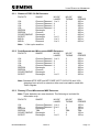
1
LOOP DETECTOR HANDBOOK
`
Siemens Mobility, Traffic Solutions
Sopers Lane
Poole
Dorset
BH17 7ER
LOOP DETECTOR AND CABLE TERMINATIONS
INSTALLATION AND COMMISSIONING
HANDBOOK
THIS DOCUMENT IS ELECTRONICALLY HELD AND APPROVED
PREPARED:
Roy Bowen / Dave Martin
FUNCTION:
Senior Group Leader
DATE:
13/03/2013
ISSUE:
13
Siemens plc 2013. All rights reserved.
The information contained herein is the property of Siemens plc and is supplied without liability for
errors or omissions. No part may be reproduced or used except as authorised by contract or other
written permission. The copyright and the foregoing restriction on reproduction and use extend to all
media in which the information may be embodied.
667/HE/20663/000
Issue 13
Page 1
LOOP DETECTOR HANDBOOK
SAFETY WARNING
HEALTH AND SAFETY AT WORK
Safety of Installation and Maintenance Personnel
In the interests of health and safety, when installing, using or servicing this
equipment the following instructions must be noted and adhered to:
(i)
Only skilled or instructed personnel with relevant technical knowledge and
experience, who are also familiar with the safety procedures required when
dealing with modern electrical/electronic equipment are to be allowed to use
and/or work on the equipment. All work shall be performed in accordance with
the Electricity at Work Regulations 1989.
(ii) Such personnel must take heed of all relevant notes, cautions and warnings in
this Handbook and any other Document or Handbook associated with the
equipment including, but not restricted to, the following:
(a) The equipment must be correctly connected to the specified incoming
power supply.
(b) The equipment must be disconnected/isolated from the incoming
power supply before removing any protective covers or working on any
part from which the protective covers have been removed.
(c) Any power tools and equipment must be regularly inspected and
tested.
(d) Any personnel working on site must wear the appropriate protective
clothing, e.g. reflective vests, etc.
Safety of Road Users
It is important that all personnel are aware of the dangers to road users that could
arise during installation, repair and maintenance of traffic control equipment.
Ensure that the junction area is coned and signed as necessary to warn motorists
and pedestrians of any dangers and to help protect the personnel working on the
site.
667/HE/20663/000
Issue 13
Page 2
LOOP DETECTOR HANDBOOK
TABLE OF CONTENTS
SAFETY WARNING ........................................................................................................ 2
1.
INTRODUCTION...................................................................................................... 5
1.1
Purpose ............................................................................................................ 5
1.2
Scope ................................................................................................................ 5
1.3
Related Documents .......................................................................................... 5
1.3.1
Other STC Traffic Installation Handbooks.................................................. 5
1.3.2
Peek/Sarasota Detector Handbooks .......................................................... 5
1.3.3
Maintenance Provision for Peek/Sarasota Detectors ................................. 5
1.3.4
Siemens Self-Tune Detectors .................................................................... 5
1.4
Issue State ........................................................................................................ 6
1.5
Glossary ............................................................................................................ 6
2.
INSTALLATION OF TRAFFIC LOOPS AND FEEDER CABLES IN SLOTS ............ 7
2.1
Loop Cable and Slot Dimensions ...................................................................... 7
2.2
Positioning of Loops and Loop Tails/Feeders ................................................... 7
2.2.1
Metal Reinforcing ....................................................................................... 7
2.2.2
Buried Metal Objects.................................................................................. 7
2.2.3
Buried Cables ............................................................................................ 8
2.2.4
Surface Objects ......................................................................................... 8
2.2.5
Blast Furnace Slag .................................................................................... 8
2.2.6
Loop Tails .................................................................................................. 8
2.2.7
Feeders...................................................................................................... 9
2.3
Loop Configurations .......................................................................................... 9
2.3.1
Replacement Controllers ........................................................................... 9
2.3.2
Replacement VA Loops ............................................................................. 9
2.3.3
Replacement SDE/SA Loops ..................................................................... 9
2.3.4
Use of Soundmark Test Sets ..................................................................... 9
2.3.5
Procedure for Marking Position of Diamond Loops Prior to Slot Cutting .. 10
2.3.6
Chevron type loops – marking of loops .................................................... 10
2.3.7
UD Loops – SDE/SA, SCOOT, Count and Queue ................................... 11
2.3.8
Turning Loops and SDE/SA Loops .......................................................... 12
2.3.9
MOVA Loops ........................................................................................... 12
2.3.10 Special Loops .......................................................................................... 13
2.4
Loop Slot Details ............................................................................................. 13
2.5
Loop Turns and Feeder Lengths ..................................................................... 13
2.5.1
Siemens ST4R / SLD4 Detectors ............................................................ 14
2.5.2
Peek/Sarasota and Microsense MXED Detectors ................................... 14
2.5.3
Plessey ST and Microsense MSE Detectors ........................................... 14
2.6
Cable Laying and Slot Backfilling Procedures................................................. 15
2.6.1
Loop Cable Laying ................................................................................... 15
2.6.2
Slots Containing Loop Cable ................................................................... 15
2.6.3
Suppliers for Resins and Compounds ..................................................... 15
2.7
Feeder Cables ................................................................................................ 16
2.8
Feeder Cable Slot Details and Backfilling ....................................................... 17
2.9
Joint Loop Tails to Feeder Cables .................................................................. 18
2.10 Cable Entry Through and Under the Kerb ....................................................... 18
2.11 Loop Detector Settings ................................................................................... 19
2.11.1 Sensitivity................................................................................................. 19
2.11.2 Presence Time ......................................................................................... 19
667/HE/20663/000
Issue 13
Page 3
LOOP DETECTOR HANDBOOK
3. CABLING ............................................................................................................... 41
3.1
Cabling and Preparation of Cables for Termination ........................................ 41
3.2
Cabling Jointing .............................................................................................. 41
3.2.1
Feeder Cable to Feeder Cable using the BICC MPJ Series Joint ............ 41
3.2.2
Feeder Cable to Loop Tails using the BICC MPJ Series Joint ................. 42
3.2.3
Preparation, Mixing and Pouring of BICC Bi-Cast Acrylic Resin .............. 43
3.2.4
Feeder Cable to Detector Loop Tails using the Heatshrink Joint ............. 44
3.3
Use of Crimp Tools in Jointing ........................................................................ 44
APPENDIX A - PRECAUTIONS TO BE TAKEN WHEN PLANNING THE
INSTALLATION AND MAINTENANCE OF TRAFFIC CONTROL EQUIPMENT IN
THE VICINITY OF LIGHT RAPID TRANSPORT SYSTEMS ........................................ 47
APPENDIX B - SETTING UP MICROSENSE / PEEK / SARASOTA DETECTOR
UNITS ........................................................................................................................... 49
INDEX ........................................................................................................................... 50
FIGURES
Figure 1 - Marking out Diamond Loops ...................................................................................... 20
Figure 2 - Table of Dimensions for Diamond Loops .................................................................. 20
Figure 3 - Marking Out Chevron Loops ...................................................................................... 22
Figure 4 - Typical Loop Configurations with UD Dimensions – Diamonds................................. 23
Figure 5 - Typical Loop Configurations with UD Dimensions – Chevrons ................................. 24
Figure 6 - Typical SCOOT Loop Leading Dimensions ............................................................... 25
Figure 7 - Typical Count Loop Leading Dimensions .................................................................. 25
Figure 8 - Rectangular SDE/SA Loops ...................................................................................... 26
Figure 9 - Rectangular Turning Loops ....................................................................................... 26
Figure 10 - Chevron SDE/SA Loops .......................................................................................... 27
Figure 11 - MOVA Loops One Way Street or Dual Carriageway ............................................... 28
Figure 12 - MOVA Loops Two Way Carriageway ...................................................................... 28
Figure 13 - Special Purpose Loops ............................................................................................ 29
Figure 14 - Slot Details .............................................................................................................. 30
Figure 15 - Maintaining 50 mm Covering at Crossovers ............................................................ 30
Figure 16 - Cutting Away Sharp Corners ................................................................................... 31
Figure 17 - Slot Corners Protected by Corner Pieces ................................................................ 31
Figure 18 - Standard Loop Configurations (a) ........................................................................... 32
Figure 19 - Standard Loop Configurations (b) ........................................................................... 33
Figure 20 - Standard Loop Configurations (c) ............................................................................ 34
Figure 21 - Distance X, Y and Z Loops to Stop Line .................................................................. 34
Figure 22 - Distance SDE-SA Loops to Stop Line ..................................................................... 35
Figure 23 - Dimensions – 1 Lane Counting Loop ...................................................................... 35
Figure 24 - Dimensions – 2 Lane N Counting Loops ................................................................. 36
Figure 25 - Dimensions – 3 Lane N Counting Loops ................................................................. 37
Figure 26 - Dimensions – 2 Lane N+1 Counting Loops ............................................................. 38
Figure 27 - Dimensions – 3 Lane N+1 Counting Loops ............................................................. 39
Figure 28 - Cabling Through the Kerb ....................................................................................... 39
Figure 29 - Cabling Under the Kerb ........................................................................................... 40
Figure 30 - Preparation of Armoured Cable End ....................................................................... 46
Figure 31 - Armoured Cable to Armoured Cable Joint ............................................................... 46
667/HE/20663/000
Issue 13
Page 4
LOOP DETECTOR HANDBOOK
1.
INTRODUCTION
1.1
Purpose
This handbook is one of a series of General Traffic handbooks that cover
common aspects of planning, installation and commissioning of STC traffic
controllers and associated street equipment.
1.2
Scope
This handbook describes the procedures for the installation and
commissioning of slots, loop detectors, cabling of loops and cable
terminations.
1.3
Related Documents
1.3.1 Other STC Traffic Installation Handbooks
General Principles Installation Handbook
667/HE/20661/000
Installation Testing Handbook
667/HE/20664/000
Above Ground Detectors Handbook
667/HE/20665/000
ST4R Loop Detector Handbook
667/HB/27663/000
SLD4 Loop Detector Handbook
667/HB/45200/000
Helios Signals and Poles Handbook
667/HB/30000/000
1.3.2 Peek/Sarasota Detector Handbooks
The handbooks for the Peek/Sarasota detectors can be obtained from Peek
Ltd., Kingsworthy, Hampshire SO23 7QA.
These handbooks contain full details and should be consulted when installing
and operating Peek/Sarasota detectors.
1.3.3 Maintenance Provision for Peek/Sarasota Detectors
The manufacturer’s MP documents for the relevant detector must be
consulted before any detector installation, commissioning or maintenance
work is carried out.
1.3.4 Siemens Self-Tune Detectors
667/1/27663/000 – Siemens ST4R Detector
667/1/45200/001 – Siemens SLD4 Detector
667/1/17180/etc - Note that these detectors are no longer available and the
handbook is only applicable where sites equipped with existing detectors are
to be maintained.
667/HE/20663/000
Issue 13
Page 5
LOOP DETECTOR HANDBOOK
1.4
1.5
Issue State
Pages
Current Issue
Type
Part ID
All
13
Meridian
667/HE/20663/000
Glossary
UD
LRT
SDE/SA
SCOOT
STS
VA
Uni-directional
Light Rapid Transport
Speed Discrimination Equipment/ Speed Assessment
Split, Cycle, Offset Optimisation Technique
Site to Scale (drawing)
Vehicle Actuation
667/HE/20663/000
Issue 13
Page 6
LOOP DETECTOR HANDBOOK
2.
INSTALLATION OF TRAFFIC LOOPS AND FEEDER CABLES IN SLOTS
Before the work is carried out, the tools listed in the General Principles
Installation handbook (see section 1.3.1) should be available.
2.1
Loop Cable and Slot Dimensions
Loop slots are cut into road surfaces for the installation of the following loop
cables:
998/4/70671/001
50/0.25 EPR insulated
998/4/85264/000
30/0.25 EPR insulated
998/4/82021/000
30/0.25 EPR/PCP insulated
The works specification specifies cable to be used.
Slots for the installation of cables must be of sufficient width to permit the free
entry of cables. Minimum slot widths are as listed:
998/4/85264/000
6 mm
998/4/82021/000
8.5 mm
998/4/70761/001
8.5 mm
Slot depths are dependent upon the number of turns in the loop or number of
conductors within a slot, as follows:
998/4/85264/000
998/4/82021/000
998/4/70671/001
4 mm x turns/conductors )
)
6.5 mm x turns/conductors )
)
6.5 mm x turns/conductors )
Plus 50 mm where
slots are cut in a black
top cover, or 25 mm
where slots are cut in
concrete.
Note: The number of turns is specified in Section 2.5.
2.2
Positioning of Loops and Loop Tails/Feeders
Loop locations containing the following obstructions should be dealt with as
indicated.
2.2.1 Metal Reinforcing
When installing loops in concrete roads containing a metallic reinforcing
mesh, there must be at least 50 mm of vertical spacing between the top of the
mesh and the bottom of the slot or loop cable. The same rule applies to metal
damp courses found in some elevated roadways.
2.2.2 Buried Metal Objects
Generally speaking, heavy metal objects such as girders and pipes have little
effect on System D and Turning Detector Loops, providing the nearest point is
50 mm or more below the loop.
667/HE/20663/000
Issue 13
Page 7
LOOP DETECTOR HANDBOOK
However, in the case of SDE/SA loops, the presence of an isolated heavy
metal object can distort the electromagnetic effect of one of the pair of loops
so that a false speed assessment is given. In these cases it is necessary to
re-site the loops 1 metre away from such objects.
Buried tramlines may present a problem as the metal tie rods sometimes
make an intermittent electrical connection with the running rails. Any
intermittent connection of this type placed under the loop can cause spurious
detector signals and it is advisable to remove the track from the area of the
loop leaving 305 mm clearance. (One metre clearance for SDE/SA loops).
2.2.3 Buried Cables
Buried Electrical Supply cables do not cause interference with Detectors.
However, SDE/SA Loops should be kept 1 metre away from heavier
armoured type of cable as the metal content could cause the distortion
mentioned in section 2.2.2.
2.2.4 Surface Objects
Loop slots should be kept one metre clear of manhole covers, drain covers,
expansion joints and similar disturbances in the road surface. Failure to
observe this can weaken the road surface and may cause subsequent
breaking up.
2.2.5 Blast Furnace Slag
Occasionally road surfaces incorporating blast furnace slag in their
construction will be encountered. This has a de-sensitising effect on detector
loops. It is not possible to detect the presence of slag from the road surface
appearance and it will usually be discovered only during commissioning in the
form of insensitive loops.
Commercial should make it clear that if this material is encountered the
customer will be responsible for work involved in overcoming the problem.
Avoiding multiple loops on a channel may increase working sensitivity. This
will involve some re-cutting and probably additional detector cards. However it
may be necessary to replace the material in the vicinity of the affected loops.
2.2.6 Loop Tails
It is advisable that loop tails are twisted with at least 10 twists per metre,
outside of the slot. See Figure 14.
However loop tails may be untwisted loop tails over a short distance where
they are taken across or along the carriageway to a connection point at the
roadside. The length of untwisted loop tails must not exceed 30 metres. No
more than 15 metres of tails from any other loop should be laid in a common
slot, and then only if the loops are driven from the same detector unit.
667/HE/20663/000
Issue 13
Page 8
LOOP DETECTOR HANDBOOK
2.2.7 Feeders
Sharing of a multi-pair feeder cable between different detectors is not
recommended. See section 2.7 for feeder types.
2.3
Loop Configurations
Loop positions will be marked prior to slot cutting, as per the positioning
instructions shown on the STS.
Loop configurations are normally of the following types:
Chevrons -
Vehicle actuation, SDE/SA
Diamonds -
Vehicle actuation (use for replacement or MOVA
only)
Rectangle -
Turning loops, SCOOT, COUNT, QUEUE and
special purpose (Required for SDE/SA for previous
detector types).
Special loops -
MOVA loops (diamonds are recommended)
2.3.1 Replacement Controllers
Replacement controllers should continue to use existing diamond Vehicle
Actuation loops where they are in good condition. Any existing SDE/SA loops
for replacement controllers should be re-cut to the new 3.6 m standard prior to
commissioning.
2.3.2 Replacement VA Loops
If a diamond loop needs re-cutting it should be re-cut as a diamond. However
if all the loops on an approach are to be re-cut then the chevron loop
configuration should be used. It is permitted to have all chevrons on one
approach and all diamonds on another subject to the following clause; where
two or more VA loops are connected to the same detector channel they must
all be to the same configuration, i.e. ALL Diamond or ALL Chevrons.
2.3.3 Replacement SDE/SA Loops
If a 3.05 m spacing SDE/SA loop needs re-cutting it should be re-cut to the
same spacing as the original unless every approach on that controller is recut. In that case the new 3.66 m spacing should be used and the controller set
up or reconfigured accordingly. Controllers cannot accept inputs from loops of
mixed spacing.
2.3.4 Use of Soundmark Test Sets
Care must be taken when selecting the loop pitch on Soundmark Test Sets.
Selecting PLE selects the old Plessey loop pitch of 3.05 m (10 ft). Selecting
GEC selects 3.6 m (12 ft) which is now common for GEC, Microsense and
NEW STC equipment.
667/HE/20663/000
Issue 13
Page 9
LOOP DETECTOR HANDBOOK
2.3.5 Procedure for Marking Position of Diamond Loops Prior to Slot Cutting
These notes are to be read in conjunction with Figure 1 and Figure 2 but
kerbs and distances from carriageway centre lines are subject to any standing
Local Authority instructions.
Refer to the STS drawing and mark the distance of the loop from the stop line,
at the road edge.
1) From this point, mark a datum line to the road centre at right angles to the
road edge.
2) Measure in from the road edge 0.3 metres and mark this point on the
datum line. This point is referred to as the datum point.
3) Measure in 1 metre from the road centre and mark this point on the datum
line. This point is referred to as the end point.
4) Measure the distance between the datum point and the end point.
Reference to Figure 2 will determine the appropriate loop configuration to
be constructed.
5) Determine the length of the loop diagonal as follows:
i)
For single loop configuration, the loop diagonal is the distance
between the datum point and end point.
ii)
For double loop configuration, the loop diagonal is the distance
between the datum point and the end point divided by 2.
iii)
For the triple loop configuration, the loop diagonal is the distance
between the datum point and the end point divided by 3.
iv)
For the quad loop configuration, the loop diagonal is the distance
between the datum point and the end point divided by 4.
6) Starting at the datum point, mark the length of the loop diagonal along the
datum line for as many diamonds as are required in the configuration.
Figure 1 shows a double loop configuration by way of example.
7) Refer to Figure 2 to determine the length of the loop side.
8) Anchor a measuring tape at the datum point and using the tape and chalk,
strike arcs either side of the datum line, whose radius equals the length of
the loop side.
9) Strike similar arcs from the point on the datum line indicating the length of
the loop diagonal. The intersection of these arcs on either side of the
datum line fixes the position of the loop corners.
10) Repeat this procedure along the datum line for the required number of
diamonds in the configuration.
11) Join up the points with chalk to form the loop configuration required.
2.3.6 Chevron type loops – marking of loops
These notes are to be read in conjunction with Figure 3 but distances from
kerbs and carriageway centre lines are subject to any local authority
instructions.
667/HE/20663/000
Issue 13
Page 10
1)
2)
3)
4)
5)
6)
7)
LOOP DETECTOR HANDBOOK
Refer to the STS drawing and mark the locations ax, bx, cz 1.1 metres
towards the top line for the loop approach distances X, Y, Z shown on
the STS drawing. (In Figure 3 loop ‘a’ is for a three lane configuration,
‘b’ is a two lane and ‘c’ is a one lane configuration loop.)
From the point ‘ax’ in loop ‘a’ mark the point ‘aa’ 1 (one) metre from the
centre line and at right angles to the kerb through point ‘ax’.
Measure the linear distance between points ‘ax’ and ‘aa’ and divide this
distance by the number of traffic lanes, which in this case is three.
Assuming S1 is 1/3 of total distance between ‘ax’ and ‘aa’, mark points
‘ax’ and ‘aa’. Mark points ‘ay’ and ‘az’ at distances D1 as shown.
At measurements D1 from points from ‘ay and ‘aa’ mark points ‘ay1’,
‘aa1’ as shown.
Loops b and c are marked out using identical techniques, but for two
and one lane respectively.
When all points referred have been marked, the points ‘xx’ can be
marked 1.1 metres from the marked points as illustrated.
When the marking of loop structure points have been completed, the
points can be joined together if necessary for slot cutting purposes.
2.3.7 UD Loops – SDE/SA, SCOOT, Count and Queue
Figure 4 illustrates a three-lane VA approach system D with diamond loops.
The UD loop overlays the actuating loop by 1/3 of the loop diagonal as shown.
Diamond UD loops can be used with Plessey ST, Microsense detectors and
Sarasota units.
Figure 5 illustrates a three-lane chevron loop approach.
This configuration can be used with Microsense, Plessey ST and Sarasota
detector units.
Note: In a two-lane approach the angle of the UD loops should be reversed to
line up with the Y and Z loops.
Figure 6 illustrates a SCOOT detector site with two carriageway loops.
The length of SCOOT Loops in the direction of travel is fixed as 2 m. This is a
compromise between a loop being short enough to detect gaps in the traffic
stream and long enough to detect stationary vehicles in a queue.
The width of the loop is dependent on site conditions and should not be less
than 1 m, or more than two lanes wide. Factors affecting the width are:
a)
The offside edge of the loop should be approximately 1 m from the
centre line of the road to reduce the probability of under-counting and
over-counting due to vehicles straddling the centre line. The centre line
is taken to be the line least occupied by vehicles in either direction and
may not coincide with the marked centre line.
b)
The loop should be sited where the risk of parking over it is minimal.
Experience has shown that double yellow lines are insufficient
safeguard and unless other physical deterrents to parking exist (e.g.
guard-rail) it is recommended the nearside edge of the loop to be
located 2 m from the kerb.
667/HE/20663/000
Issue 13
Page 11
c)
LOOP DETECTOR HANDBOOK
In the case of multi-lane links where more than one loop is provided,
the gap between two adjacent detectors on a link should be
approximately 2.5 m (based on the width of an average vehicle) so as
to balance under-counting and over-counting errors.
d)
Where carriageway width is restricted, the minimum 1m wide loop may
still be clipped by oncoming traffic. Where this problem is expected
unidirectional loops should be considered.
e)
The dimensions of the UD loop overlay are illustrated in Figure 6.
These SCOOT loop configurations can be used with Microsense,
Plessey ST, and Sarasota detector units.
Figure 7 illustrates a N+1 count loop configuration where N is the number of
traffic lanes. The length of count loops, in the direction of travel is fixed at 1.8
m. The width of loops and their spacing ‘B’ are dependent on site conditions,
these dimensions being shown on the appropriate site drawings. The distance
of the nearside loop to the kerb also varies with site conditions and should be
detailed on the site drawing.
The dimensions of the UD loop overlay are illustrated in Figure 7.
2.3.8 Turning Loops and SDE/SA Loops
Figure 8 to Figure 10 illustrate configurations for turning loops, and SDE/SA
loops. The turning loop Figure 9 can be connected to Siemens/Plessey,
Microsense and Sarasota detectors observing the calculation for loop turns
listed in section 2.5 of this document.
The rectangular loop SDE/SA configuration, Figure 8 is for connection to
Siemens/Plessey, Microsense or Sarasota detector units.
The chevron loop SDE/SA configuration Figure 10 should be used with
Sarasota MTS and Microsense MXE series detectors. This improves speed
measurement accuracy for motorcycles.
NOTE: Siemens controllers and Pelicans for new installations will be
configured for 3.66 metre speed measuring base in line with current GEC and
Microsense controllers. Earlier Plessey controllers may have been configured
for 3.05 metre speed measuring base and other manufacturers’ earlier
controllers for various different bases. When re-cutting an existing loop check
with the existing controller for the correct loop spacing.
With intersection controllers the configuration must be checked to verify the
loop spacing.
With T110 Pelicans Address 217 should be greater than 0 for 3.66 metre
speed measuring base.
2.3.9 MOVA Loops
Figure 11 and Figure 12 illustrate MOVA loops; it is recommended that
diamond loops should be used where lane width allows, with a minimum size
of 1 sq m and 1.6 m to 1.7 m in the direction of travel. Where lane width is
restricted, other loop configurations may be used. For example, where MOVA
667/HE/20663/000
Issue 13
Page 12
LOOP DETECTOR HANDBOOK
stopline is required, chevron loops away from the direction of traffic should be
used.
2.3.10 Special Loops
Figure 13 illustrates queue loops and special purpose loops whereby fixed
and limits of variable dimensions are shown. These loop configurations can
be connected to Siemens/Plessey, Microsense and Sarasota detectors
observing the calculations for loop turns as listed in section 2.5 of this
handbook.
2.4
Loop Slot Details
Loop and loop tail slots will be cut in the surface of the roadway with a motor
driven saw.
Prior to cutting the slots refer to section 2.1 to determine minimum slot widths,
and minimum slot depths. Refer to Figure 14 for typical examples.
When adjacent loops are connected to different detectors, their loop tails must
be laid in different slots spaced 150 mm apart and connected to separate
feeder cables to each detector unit.
When cutting loops, the saw blade should be lowered to form a dip in the floor
of the slots at the point where the slots cross. This will allow the extra bulk of
crossing cables to lie in the dip while still maintaining the 50 mm covering for
the top cable (See Figure 15). The same rule applies to all loops at the point
where the feeder cables join the loop.
The corners of slots should not be cut away at diamond loop crossovers but
must be cut away to ease the bend on loop cables turning through an angle of
less than 90 (See Figure 16). An alternative is to protect the cable from a
sharp corner by inserting a short length of 1 mm thick vinyl or plastic strip
formed by bending to fit the corner (Figure 17 refers).
Slots must be cleared of stones, loose material and free water before cable
laying. Drying out can be assisted by using a compressor and air line. It is not
acceptable to lay cables in a wet slot as backfilling materials do not bond to
wet surfaces although the slightly damp surface obtained after using the air
line is acceptable. (Definition of a wet slot is a slot that contains free-standing
water.)
NOTE: If the saw breaks through into the hardcore bed, work should be
stopped and the customer informed that loops cannot be installed
to this Siemens specification.
2.5
Loop Turns and Feeder Lengths
All loops shared on one detector channel are to be connected in series.
The maximum feeder length quoted below includes the total length of any
separate pairs fed back for series connection in the controller and the lengths
of loop tails.
667/HE/20663/000
Issue 13
Page 13
LOOP DETECTOR HANDBOOK
2.5.1 Siemens ST4R / SLD4 Detectors
FACILITY
SHAPE
NO.OF
LANES
NO.OF
TURNS
MAX
FEEDER
V/A
V/A
V/A
V/A
SDE/SA
SDE/SA
COUNT/QUEUE
SCOOT
MOVA
MOVA
Chevron/Diamond
Chevron/Diamond
Chevron/Diamond
Chevron/Diamond
Rectangle
Chevron
Rectangle
Rectangle
Diamond
Diamond
1 to 3
4
5
6
1
1
1
1 or 2
1 to 3
1 to 3
3
3
3
3
3
3
3
3
3
3
300 m
250 m
200 m
150 m
300 m
300 m
600 m*
600 m*
300 m
600 m*
Note: * = Not cycle sensitive
2.5.2 Peek/Sarasota and Microsense MXED Detectors
FACILITY
SHAPE
NO.OF
LANES
NO.OF
TURNS
MAX
FEEDER
V/A
V/A
V/A
V/A
SDE/SA
SDE/SA
COUNT/QUEUE
SCOOT
Chevron/Diamond
Chevron/Diamond
Chevron/Diamond
Chevron/Diamond
Rectangle
Chevron
Rectangle
Rectangle
1 to 3
4
5
6
1
1
1
1 or 2
3
3
3
3
3
3
3
3
300 m
250 m
200 m
150 m
300 m
300 m
300 m
300 m
Note: Sarasota MTS 36ZE and MTS 38ZE (667/7/21031/102 and /104)
detectors have a built-in extension timer and must not be used with
Traffic Signals.
2.5.3 Plessey ST and Microsense MSE Detectors
Note: These detectors are now obsolete. The following is included for
information only.
FACILITY
SHAPE
NO.OF
LANES
NO.OF
TURNS
MAX.
FEEDER
V/A
V/A
SDE/SA
SDE/SA
COUNT QUEUE
SCOOT
Chevron/Diamond
Chevron/Diamond
Rectangle
TBA
Rectangle
Rectangle
1 to 4
5 to 6
1
1
1
1 or 2
3
3
3
TBA
3
3
150 m
100 m
150 m
TBA
150 m
150 m
667/HE/20663/000
Issue 13
Page 14
LOOP DETECTOR HANDBOOK
2.6
Cable Laying and Slot Backfilling Procedures
2.6.1 Loop Cable Laying
The loop cable should be dry. Loops are laid starting at the kerb, running the
tails out winding the loop and returning via the same slot to the kerb. When
winding a multiple diamond loop, the cables must cross at the point where the
diamonds meet. When loops are connected to feeder cable in the crown of
the road, loops are laid starting at and returning to the crown of the road. It is
acceptable to run short lengths of loops cable pairs taped together in the soil
under the pavement or grass verge but the run should be kept as short as
possible and should not exceed 4.5 m. When longer runs are required, feeder
cables part no. 667/4/03082/etc must be used (See Section 2.7).
When a pair of tails run inside the detector pedestal or controller case they
should be taped or tied together at 100 mm spacing.
The free ends should be labelled with the loop identity using Hellerman HC7
sleeving.
2.6.2 Slots Containing Loop Cable
Slots must be backfilled immediately following the laying of cables. The
backfill of loops in the United Kingdom consists of two different techniques:
i)
Complete cover of the loop cable with dry sand to a depth of 6mm to
12mm and backfilling of the slot by hotpour bitumen.
ii)
A 10 mm cover of cables by a two-part epoxy resin, and remaining slot
backfill completed by hotpour bitumen. Note that the loop cable must
be dry as the resin will not bond to wet plastic.
Two part epoxy resins and approved hot pour bitumen are listed in section
2.6.3
Prior to backfill of slots, refer to customer’s instructions for preferred backfill.
2.6.3 Suppliers for Resins and Compounds
Epoxy Materials
1) PX212ZE
Robnorganic Systems Ltd.
Highworth Road,
South Marsten,
Swindon,
Wilts.
2) CALKTITE COLDPOUR LSM/3O
(new improved grade)
Sealocrete PLA Ltd.,
Greenfield Lane,
Rochdale,
OL11 2LD
667/HE/20663/000
Issue 13
Page 15
LOOP DETECTOR HANDBOOK
Joint Sealers for Road Expansion Joints
1) CALKTITE JOINT SEALERS
Polyurethane:
P J Sealant
or
Polysulphide:
Sealant 195
Sealocrete PLA Ltd.,
Greenfield Lane,
Rochdale,
OL11 2LD
2) CLARES BLACK JOINTING COMPOUND SM3
R.S. Clare & Co. Ltd.,
Stanhope Street,
Liverpool
L8 5RQ
Hot Pour Compounds
1) R85 or R95 -
Note that the number is the melting point in °C. To order
follow the temperature with the pack size, e.g. R85/25 for
85°C melting bitumen in 25-Kg blocks.
Colas Construction Ltd.,
Western Region
Gabriels Wharf
Water Lane
Exeter
Devon
EX2 8BZ
2) PLIASTIC 77 or 90 (Export Only)
Expandite Ltd
1 – 9 Chase Road
London
NW10 6PS
2.7
Feeder Cables
In areas where the customer has no special requirements the following
instructions are to be followed.
A polythene sheathed feeder cable must be used when more than 4.5 m (15
feet) of feeder is to be laid directly in the soil under the pavement or soft
verges.
667/HE/20663/000
Issue 13
Page 16
LOOP DETECTOR HANDBOOK
The feeder cable is supplied with 1.5 mm or 2.5 mm copper conductors and
may be manufactured with or without steel wire armour to meet customer
specification. The referred types are 1 or 2 pair non-armoured cables with 1.5
mm2 conductors and an orange coloured outer covering. Armoured cable, also
orange coloured and with 1.5 mm2 conductors, is recommended where the
joint between loop tails and feeder cable is made in the road, or where ducts
do not protect cables.
2
2
It is most important that the 2 cores of each pair are identified and correctly
connected. With 2 pair Quad cable, opposite cores always form a pair. (Red is
opposite blue and yellow is opposite black). With 3 and 4 pair cable the pairs
are twisted and it is not possible to identify pairs by colours alone.
The feeder must be joined to the loop ends using crimp connectors encased
in an appropriate joint box. The crimp connectors must be suitable for joining
1.5 mm2 / 2.5 mm2 solid copper feeder cable conductors to 1.5 mm2 / 2.5 mm2
stranded loop conductors.
The feeder cable codes are as follows:
1 pair
2 pairs
1.5 mm2 Plain cable
1.5 mm2 Armoured cable
998/4/85263/900
998/4/85263/901
998/4/85263/000
998/4/85263/001
The following 2.5 mm2 cables are no longer recommended but are listed here
for completeness:
1 pair
2 pairs
3 pairs
4 pairs
2.8
2.5 mm2 Plain cable
2.5 mm2 Armoured cable
667/4/03082/900
667/4/03082/901
667/4/03082/902
667/4/03082/903
667/4/03082/000
667/4/03082/001
667/4/03082/002
667/4/03082/003
Feeder Cable Slot Details and Backfilling
Feeder cable slots will be cut in the surface of the roadway using a motor
driven saw.
Slots must be cut at least 2 mm wider than the cable being installed and deep
enough to allow 65 mm of cover.
The minimum slot widths are as follows:
1.5 mm2 plain cable
1 pair
2 pairs
10mm
12mm
14mm
16mm
2.5 mm2 plain cable
1 pair
2 pairs
3 pairs
4 pairs
667/HE/20663/000
1.5 mm2 armoured cable
12mm
14mm
18mm
20mm
2.5 mm2 armoured cable
16mm
18mm
22mm
24mm
Issue 13
Page 17
LOOP DETECTOR HANDBOOK
Backfilling shall be with fine cold asphalt rammed into the slot and finished
with a surface layer of hotpour of 20 mm nominal depth.
2.9
Joint Loop Tails to Feeder Cables
STC approved joint is the acrylic joint to specification 915/4/03118/etc. These
joints can be used in underground chambers, soil and encapsulated in slots in
carriageways. When customers specify heat shrink joints, joints to
specification 667/4/15084/etc. will be used. These joints are only suitable for
encapsulation in slots in carriageways.
Where joints are installed in the road surface, the joint is to be made within
one metre of the loop, or the nearest loop to the feeder cable where a series
of loops are joined together by tails. Slot widths for the various joints are as
follows:
915/4/03118/000
40 mm
915/4/031188001
55 mm
When using heat shrink joints 667/4/15084/etc feeder slots to be widened by
10mm for insertion of joint.
Guidance for loop to feeder joint connections as follows:
915/4/03118/000 - Use with 3 pr and 4 pr cables, maximum loop conductor 8
915/4/03118/001 - Use with 3 pr and 4 pr cables, maximum loop conductor 12
667/4/15084/000 - 1, 2 or 3 loops to a 1 pair cable
667/4/15084/001 - 2 or 3 loops to a 1 pair cable, 2 loops to a 2 pair cable
667/4/15084/002 - 2 or 3 loops to a 1 pair cable, 3 loops to a 3 pair cable
667/4/15084/003 - 2 or 3 loops to a 1 pair cable, 4 loops to a 4 pair cable
The depth of slots for joints must be such that their cover of epoxy/asphalt/hot
pour is not less than 65 mm. Prior to commencing backfill, the joint shall be
laid evenly on the floor of the slot then covered with epoxy resin, and if
possible left for 30 minutes before commencing the next operation. Following
the application of epoxy resin, fine cold asphalt should be rammed into the
slot built up to approximately 10 mm below road level. Following this, the fine
cold asphalt must be covered with hot bitumen and allowed to cool.
2.10
Cable Entry Through and Under the Kerb
The feeder cable or, where permitted, short lengths of loop tails as described
in section 2.6.1, shall be through a duct laid through or under the kerb as
shown in Figure 28 and Figure 29. The concrete or cold asphalt shall be
compacted into a smooth bed between the floor of the slot and the duct. The
cable(s) shall be laid on this bed before backfilling to the road surface.
667/HE/20663/000
Issue 13
Page 18
LOOP DETECTOR HANDBOOK
2.11
Loop Detector Settings
2.11.1 Sensitivity
For normal VA purposes the detectors should be set to give bicycle detection.
This requires a sensitivity setting of 0.01% or 0.02%. If the setting is too
sensitive the detector will be unduly sensitive to vehicles in adjacent lanes.
This is most likely where a single small loop is installed on a detector channel
i.e. without sharing. If this is a problem on a particular site the sensitivity may
be reduced but not to below 0.04%.
For SDE/SA the two loops must be set to the same sensitivity.
For SCOOT, the sensitivity setting depends on the feeder length and loop size
(all SCOOT loops are 2 metres in the direction of travel and vary in width).
The diagram below may be used as a guide to sensitivity settings. However
the target response for a SCOOT detector is that a ‘detect’ output should start
as the first metal part of a normal 4-wheeled vehicle crosses the front of the
loop and no response should be obtained from vehicles in adjacent lanes.
This should be confirmed or the sensitivity altered to achieve this before
leaving the site.
MOVA loops should be set to medium sensitivity (~0.1%) with the exception of
stop line loops that should be high sensitivity (~0.1% - 0.5%).
6
0.02% - Not
recommended
5
Loop Width (metres)
4
0.04%
3
0.08%
2
1
0
0m
100m
200m
300m
Feeder Length
2.11.2 Presence Time
This is defined as the time for which a ‘detect’ output is held when a vehicle
enters and stops within a loop. After the presence time has expired the
detector retunes to the new value of loop inductance. For Road Traffic use it
is normally set to 4 minutes.
667/HE/20663/000
Issue 13
Page 19
LOOP DETECTOR HANDBOOK
Figure 1 - Marking out Diamond Loops
(Use for replacement or MOVA only)
See Figure 21 for distance from stop line.
Figure 2 - Table of Dimensions for Diamond Loops
(Use for replacement or MOVA only)
Distance between Datum
Point and End Point within
the range
Loop Configuration
1.2 – 3.6 metres
Single
3.7 – 7.2 metres
Double
7.3 – 10.8 metres
Triple
10.9 – 14.4 metres
Quad
667/HE/20663/000
Issue 13
Example
◊
◊◊
◊◊◊
◊◊◊◊
Page 20
LOOP DETECTOR HANDBOOK
Calculation of Loop Dimensions
Loop Diagonal
Feet
4.00
4.50
5.00
5.50
6.00
6.50
7.00
7.50
8.00
8.50
9.00
9.50
10.00
10.50
11.00
11.50
12.00
667/HE/20663/000
Length of Side
Metres
1.22
1.37
1.52
1.68
1.83
1.98
2.13
2.29
2.44
2.59
2.74
2.90
3.05
3.20
3.35
3.51
3.66
Feet
2.83
3.18
3.54
3.89
4.24
4.60
4.95
5.30
5.66
6.01
6.36
6.72
7.07
7.42
7.78
8.18
8.49
Issue 13
Metres
0.86
0.97
1.08
1.19
1.29
1.40
1.51
1.62
1.72
1.83
1.94
2.05
2.16
2.26
2.37
2.48
2.59
Page 21
Distance from stop line
LOOP DETECTOR HANDBOOK
Figure 3 - Marking Out Chevron Loops
ax
D1
D1
ay
D1
az
aa
1.1 m
0.3 m
xx
xx
aa1
ay1
1m
xx
Distance from stop line
xx
bx
by
bz
1m
1.1 m
0.3 m
xx
xx
Direction
of traffic
by1
Distance from stop line
xx
cx
cy
See Figure 21 for
distance from stop
line
1.1 m
0.3 m
xx
1m
xx
667/HE/20663/000
Issue 13
Page 22
LOOP DETECTOR HANDBOOK
Figure 4 - Typical Loop Configurations with UD Dimensions – Diamonds
1m
0.3 m to kerb edge
Loop tails
U/D
1/3 x
x
1m
Maximum length of
feeder cable = 150 m
(obsolescent, use for
replacement only)
667/HE/20663/000
Issue 13
Page 23
LOOP DETECTOR HANDBOOK
Figure 5 - Typical Loop Configurations with UD Dimensions – Chevrons
X
0.3 m to kerb edge
0.3 m
U/D
0.2 m
1m
U/D loop overlaps X loop
by 0.2 m (0.3 m in
direction of travel)
667/HE/20663/000
Issue 13
X = 1 m, subject
to local survey
Page 24
LOOP DETECTOR HANDBOOK
Figure 6 - Typical SCOOT Loop Leading Dimensions
U/D
NA
0.3 m
2m
0.15 m
1m
2.5 m
Figure 7 - Typical Count Loop Leading Dimensions
A
1.8 m
0.15 m
1m
B
Dimension A = 0.27m
Dimension B = Refer to Figure 23 to Figure 27.
Dimensions to be marked up on STS drawing after installation.
667/HE/20663/000
Issue 13
Page 25
LOOP DETECTOR HANDBOOK
Figure 8 - Rectangular SDE/SA Loops
Refer also to section 2.3.8 and Figure 10 for SDE/SA loop options.
1.2 m – 3.6 m
0.3 m
Distance from
stop line
1m
x
Road
centre
1m
1.8 m
Direction of
travel
x = Refer to note in section 2.3.8 for dimensions.
Note that on dual carriageways the loops should be 0.3 metres from the central
reservation.
Distance from stop line – See Figure 22.
All loops to be 3 turns.
Figure 9 - Rectangular Turning Loops
Length 1.8 m – 3.6 m
Width 1.8 m – 7.6 m
Maximum of 150 m
feeder cable
667/HE/20663/000
Issue 13
Page 26
LOOP DETECTOR HANDBOOK
Distance from stop line
Figure 10 - Chevron SDE/SA Loops
Armoured
feeder cable
Direction
of traffic
1.1 m
1m
1m *
3.66 m
Joint
Joint
0.3 m
* On dual carriageways the loops should be 0.3 metres from the central reservation.
Distance from stop line – See Figure 22.
All loops to be 3 turns.
667/HE/20663/000
Issue 13
Page 27
LOOP DETECTOR HANDBOOK
Figure 11 - MOVA Loops One Way Street or Dual Carriageway
0.4 m
Lane 1
0.8 m
0.8 m
Lane 2
0.8 m
0.8 m
Lane 3
0.4 m
1.6 m to 1.7 m
Figure 12 - MOVA Loops Two Way Carriageway
0.6 m
0.8 m
0.8 m
0.4 m
1.6 m to 1.7 m
667/HE/20663/000
Issue 13
Page 28
LOOP DETECTOR HANDBOOK
Figure 13 - Special Purpose Loops
1.4 m – 15.0 m
1.2 m
(a) Call and Extend loops
Non-bicycle sensitive. Not approved for use on roads in UK.
1.4 m – 15.0 m
1.2 m
(b) Call and Extend loop
Non-bicycle sensitive. Not approved for use on roads in UK.
1.8 m – 3.0 m
4.8 m
(c) Queue loop
667/HE/20663/000
Issue 13
Page 29
LOOP DETECTOR HANDBOOK
Figure 14 - Slot Details
Road surface
Hot pour compound
8.5mm min
50mm covering
(25mm in concrete)
Epoxy material or sand
Loop cables
Figure 15 - Maintaining 50 mm Covering at Crossovers
Floor of both slots dipped at
crossover
Loop cables in crossing slot
Note: Not to be carried out at diamond crossovers
667/HE/20663/000
Issue 13
Page 30
LOOP DETECTOR HANDBOOK
Figure 16 - Cutting Away Sharp Corners
Figure 17 - Slot Corners Protected by Corner Pieces
SLOT WIDTH
998/4/85264/000 8mm
998/4/82021/000 10mm
998/4/70671/001
1mm Vinyl/Plastic corner
protection pieces
SLOT WIDTH to be
widened to
998/4/85264/000 10mm
998/4/82021/000 12mm
998/4/70671/001
to accept 2 off corner
protection pieces
667/HE/20663/000
Issue 13
Page 31
LOOP DETECTOR HANDBOOK
Figure 18 - Standard Loop Configurations (a)
(Diamonds are largely obsolescent, use for replacement or MOVA only)
667/HE/20663/000
Issue 13
Page 32
LOOP DETECTOR HANDBOOK
Figure 19 - Standard Loop Configurations (b)
(Diamonds are largely obsolescent, use for replacement or MOVA only)
667/HE/20663/000
Issue 13
Page 33
LOOP DETECTOR HANDBOOK
Figure 20 - Standard Loop Configurations (c)
(Diamonds are largely obsolescent, use for replacement or MOVA only)
THIS CONFIGURATION TO COVER 6 LANES MAXIMUM AS SHOWN
Figure 21 - Distance X, Y and Z Loops to Stop Line
Distance from Stop
Line to X loop
Number of Loops
Distance from Stop
Line to Y loop
Distance from Stop
line to Z loop
39 m
3
25 m
12 m
30 m
3
18 m
7m
18 m
2
-
6m
667/HE/20663/000
Issue 13
Page 34
LOOP DETECTOR HANDBOOK
Figure 22 - Distance SDE-SA Loops to Stop Line
Traffic Signal and Pelican Extension
Distance
Double SDE
79 metres
Triple SDE – Inner
91 metres
Triple SDE – Outer
159 metres
Speed Assessment
151 metres
Note: For full details refer to HA Specification MCE 0108B.
Figure 23 - Dimensions – 1 Lane Counting Loop
For full details, refer to HA specification MCE 0115A
Distance across Road (metres)
5
4.5
4
3.5
Centre of Road
3
2.5
2
1.5
A Loop
1
0.5
0
2
2.5
3
3.5
4
4.5
Width of Road (metres)
667/HE/20663/000
Issue 13
Page 35
LOOP DETECTOR HANDBOOK
Figure 24 - Dimensions – 2 Lane N Counting Loops
For full details, refer to HA specification MCE 0115A
8
7.5
7
6.5
6
Centre of Road
Distance across Road (metres)
5.5
5
4.5
A Loop
4
3.5
3
B Loop
2.5
2
B Loop
1.5
1
0.5
0
3
4
5
6
7
8
Width of Road (metres)
667/HE/20663/000
Issue 13
Page 36
LOOP DETECTOR HANDBOOK
Figure 25 - Dimensions – 3 Lane N Counting Loops
For full details, refer to HA specification MCE 0115A
14
13
Distance across Road (metres)
12
11
10
Centre of Road
A Loop
9
8
A Loop
7
6
B Loop
5
B Loop
4
3
2
C Loop
1
0
7
8
9
10
11
12
Width of Road (metres)
667/HE/20663/000
Issue 13
Page 37
LOOP DETECTOR HANDBOOK
Figure 26 - Dimensions – 2 Lane N+1 Counting Loops
For full details, refer to HA specification MCE 0115A
Centre of Road
8
7.5
Not
recommended
below this width
7
6.5
6
Distance across Road (metres)
5.5
A Loop
5
4.5
4
3.5
B Loop
3
B Loop
2.5
2
1.5
C Loop
1
0.5
0
3
667/HE/20663/000
4
5
6
Width of Road (metres)
Issue 13
7
8
Page 38
LOOP DETECTOR HANDBOOK
Figure 27 - Dimensions – 3 Lane N+1 Counting Loops
For full details, refer to HA specification MCE 0115A
Distance across Road (metres)
12
11
Not
recommended
below this width
10
Centre of Road
A Loop
9
A Loop
8
7
6
B Loop
B Loop
5
4
C Loop
3
2
D Loop
1
0
7
8
9
10
11
12
Width of Road (metres)
Figure 28 - Cabling Through the Kerb
Footway
Kerb
Bitumen
Asphalt backfill
Slot
Cable
Bottom of slot
Duct through kerb
Concrete or asphalt
backfill
667/HE/20663/000
Issue 13
Page 39
LOOP DETECTOR HANDBOOK
Figure 29 - Cabling Under the Kerb
Footway
Kerb
Bitumen
Asphalt backfill
Slot
Cable
Bottom of slot
Concrete or asphalt
backfill
Duct under kerb
667/HE/20663/000
Issue 13
Page 40
LOOP DETECTOR HANDBOOK
3.
CABLING
This section applies to paired loop feeder cable and multicore cable to
Detector Pole Boxes and Signals Heads.
3.1
Cabling and Preparation of Cables for Termination
1. Traffic intersections are cabled in accordance with the schedule shown on
the STS drawing.
2. Prior to commencing cabling, the operation should be planned so that, as
far as possible, cable drums are handled as little as possible and the
number of cable drums transported to site reduced to a minimum. During
the laying of cable, cable jacks or drum rollers should be used to
advantage, especially on long cable runs.
3.2
Cabling Jointing
In traffic signal installation work there are two types of cable joints that have to
be made. These are feeder cable to feeder cable and feeder cable to detector
loop tails. The feeder cable may be armoured or un-armoured.
All jointing of feeder cable to feeder cable should use the BICC MPJ series
(MPJ1 or MPJ2) resin filled torpedo joint unless the customer specifies other
jointing systems.
Jointing of feeder cable to detector loop tails will use the same joint unless the
Authority specifies a heatshrink or other type of joint. Refer to section 2.7 for
identification of pairs.
Some Authorities are specifying joints based on short lengths of cable duct
with cable duct plugs. The manufacturers’ instructions must be followed in
particular in ensuring good contact and joint sealing. Any instructions
regarding moisture-removing precautions must be strictly adhered to.
3.2.1 Feeder Cable to Feeder Cable using the BICC MPJ Series Joint
Ignore instructions marked * referring to armour where not applicable.
Assumes MPJ1or MPJ2 jointing kit used. See Figure 30 and Figure 31.
The following additional items are also required if armoured feeder is to be
joined:
PVC insulated wire - green/yellow 6 sq. mm.
Earthing bands – 2 off.
Worm drive clips – 2 off.
*
Cut the earth wire to length and bare the ends.
*
Using the hacksaw provided in the installation tool kit cut through the
outer insulation of one cable approximately 120 mm from the end ensuring
that the armour is well scored.
667/HE/20663/000
Issue 13
Page 41
LOOP DETECTOR HANDBOOK
*
Remove the outer insulation and break off the armour by repeated
bending.
*
Cut through the outer insulation 50 mm from the end of the armour
without cutting into the armour.
*
Remove outer insulation.
*
Terminate the bedding so that 10 mm projects beyond the armour.
*
Slide a worm drive hose clip over the cable. Open the armour and
position the earthing band underneath. Lay the earthing wire end with the
armour and bring the worm drive hose clip forward to secure the earthing wire
and armour down onto the earthing band. Tighten the clip to achieve a good
mechanical and electrical joint.
For non-armoured cable cut through the outer insulation of one cable
approximately 120 mm from the end to reveal the inner cores with their
insulation.
Repeat for the other cable end.
Cut cable cores to length ensuring that the joints will be staggered and crimp
using blue crimps.
Insulate each crimped joint as required.
Cut the stepped ends of the shell halves so that they fit over the outer
insulation of the cable without interference, but at the same time, giving
minimum clearance in order to avoid eccentricity.
Check, and adjust as necessary, the clearances between the joint
components and the joint components and the shell.
Clean the outer insulation at the box entry positions with a dry cloth. Position
the box shells centrally round the joint and secure them together by hand,
tightening the cable ties provided, ensuring that the tightening does not distort
the half shells and thus destroy the resin seal. Remove the backing tape from
the sealing tape provided and wrap the sealing tape round each stepped end
and stretching it sufficiently to form a seal between shells and outer insulation.
Mix the resin in accordance with the instructions given in section 3.2.3 and
pour resin into the box through the central opening until the box is full.
Fit the central filling cover plate by bending it slightly along its length and
snapping it into position.
If the joint is not positioned at its final location prior to pouring the resin it must
be left to cure before being placed in its final location.
3.2.2 Feeder Cable to Loop Tails using the BICC MPJ Series Joint
Assumes MPJ1 and MPJ2 jointing kit used.
Prepare feeder cable as described in section 3.2.1.
Cut cable cores and detector loop tails to length ensuring that the joints will be
staggered and crimp using blue crimps.
Insulate each crimped joint as required.
667/HE/20663/000
Issue 13
Page 42
LOOP DETECTOR HANDBOOK
Cut the stepped ends of the shell halves so that they fit over the outer
insulation of the cable and the bundle of detector loop tails without
interference but, at the same time, giving minimum clearance in order to avoid
eccentricity.
Continue as described in section 3.2.1.
3.2.3 Preparation, Mixing and Pouring of BICC Bi-Cast Acrylic Resin
The resin is provided as a two-part mix. The powder component is in a plastic
bag and the liquid component in a tin.
Check the last two digits of the style reference numbers are identical, e.g.
BC 73190 - 57 (Powder)
BC 73195 – 57 (Liquid)
If the last two digits are not the same, on no account should they be mixed
together.
Check that the use-by date printed in the powder label has not been
exceeded.
Mixing must take place away from naked lights. Avoid exposure of the tin to
hot sun as heat could cause a pressure build-up in the tin. In the event of
such exposure the tin of liquid should be pierced at arms length to guard
against a jet of wet vapour onto the face.
Carefully unfasten the bag, unroll the free end and remove the clip.
Allow air into the bag and re-roll the open end several times round the clip to
effect a seal and entrap air.
Grip the bag securely at each end and up-end it 4 or 5 times to disturb the
powder settlement, paying particular attention to the bag corners.
Open the tin of liquid, unroll and open the bag. Pour all the contents of the tin
into the bag ensuring spillage of liquid does not occur.
Fold the corners of the bag to the middle and roll around the clip several times
to effect a seal and entrap air.
Grip the bag securely at each end and thoroughly mix the liquid and powder.
This is best achieved by holding the bag vertically for ¼ minute to allow the
powder to settle into the liquid, shaking the bag top to dislodge powder from
the corners and repeatedly oscillating the bag through 180 degrees with a
tumbling action (speeding up as mixing progresses) for ½ minute. Finish off
with a more vigorous end to end shaking of the bag for a further ¼ minute.
Remove the clip and re-wrap it diagonally across the corner of the open end
of the bag to provide a convenient sized pouring hold and handle to assist the
pouring operation. The resin should be poured through the filling port
immediately after mixing. Top up if necessary.
Fit the cover plate.
Adequately support the joint both underneath at each end before backfilling
the joint hole. Backfilling may take place immediately or be delayed until the
resin has set hard.
667/HE/20663/000
Issue 13
Page 43
LOOP DETECTOR HANDBOOK
CAUTION: Certain individuals are susceptible to sensitisation and if a
skin rash develops medical advice should be sought. Any resin
splashes on the skin should be removes before the resin hardens.
3.2.4 Feeder Cable to Detector Loop Tails using the Heatshrink Joint
The part number of the kit to be used is 667/4/15084/etc.
There are 4 variants. Their uses and the length of armour to be stripped
(where applicable) are given below:
000
-
1 pair to 1, 2 or 3 loops
(80 mm)
001
-
2 pair to 2 loops or
1 pair to 2 or 3 loops
(100 mm)
3 pair to 3 loops or
1 pair to 2 or 3 loops
(120 mm)
4 pair to 4 loops or
1 pair to 2 or 3 loops
(135 mm)
002
003
-
Feed the outer sleeves onto the feeder cable.
For armoured cable:
Using the hacksaw provided in the installation tool kit cut through the
outer insulation of the cable at the dimension given above from the end
ensuring that the armour is well scored.
Remove the outer insulation.
Break off the armour by repeated bending.
Terminate bedding so that 10 mm projects beyond the armour.
For un-armoured cable:
Remove the outer insulation at the dimension given above for stripping
armour.
Cut cable cores to length ensuring that the joints will be staggered and crimp
as described in section 3.3.
Wrap black mastic tape around the end of the armoured cable, in and around
the connectors and loop tails and squeeze.
Centre up the outer sleeve allowing 75 mm overlap on the armour cable and
clean cable ends with cleaning pads.
Starting up at the centre of the joint and using a heating torch shrink evenly to
both ends until mastic sealant is visible.
Allow the joint to cool before applying any mechanical strain.
3.3
Use of Crimp Tools in Jointing
The following procedure is to be adopted when preparing cables for jointing in
BICC or similar joint kits.
667/HE/20663/000
Issue 13
Page 44
LOOP DETECTOR HANDBOOK
Prepare the feeder cable as detailed for the type of joints and the joint kit to
be used.
Cut the conductors to length ensuring that the joints will be staggered within
the joint shell. The outer sheath must project at least 50 mm into the joint shell
in the finished joint and no crimp joint should be closer than 75 mm to the end
of the shell.
Remove 12 mm of insulation from each core.
Slide a rubber grommet over the core.
Prepare loop tail ends as in section 3.2.4. If one tail end only is to be crimped
in a crimp sleeve, remove 24 mm of insulation from the tail and double the
end back prior to crimping. This will ensure that a secure crimp is made.
Insert the prepared core and tail end(s) into opposite ends of the crimp
sleeve, allowing a 2 mm protrusion at each end and crimp both ends of the
sleeves using the correct crimping tool. The crimps must be made in the same
plane.
Position the rubber grommet in the centre of the crimped sleeve and visually
inspect the completed crimp to ensure that no loose strands are present.
Apply a pull test to each crimp joint.
Complete the assembly of the joint in accordance with the appropriate
section.
667/HE/20663/000
Issue 13
Page 45
LOOP DETECTOR HANDBOOK
Figure 30 - Preparation of Armoured Cable End
Figure 31 - Armoured Cable to Armoured Cable Joint
667/HE/20663/000
Issue 13
Page 46
LOOP DETECTOR HANDBOOK
APPENDIX A - PRECAUTIONS TO BE TAKEN WHEN PLANNING
THE INSTALLATION AND MAINTENANCE OF TRAFFIC CONTROL
EQUIPMENT IN THE VICINITY OF LIGHT RAPID TRANSPORT
SYSTEMS
Introduction
The details given in this Appendix are designed to assist in the planning of
installation and maintenance of traffic control equipment in the vicinity of LRT
systems. Advice is given on the prevention of accidental contact between LRT
track or vehicles and street furniture, which would permit traction current to
return through the Traffic control equipment earthing system.
Reference Documents
The following documents were consulted in the preparation of this Appendix:
GEC Alsthom Transportation Projects Limited report no. TPL25/S/026 –
Earthing and Bonding Policy for Manchester Metrolink.
GEC Alsthom Transmission and Distribution Projects Limited report no. S/Sdq
856 – Metrolink Report on Touch Voltages for Phase 1 dated 19th October
1990. Reference 732/XREP27.
Background
LRT track and the vehicles running on it may be at a potential other than the
local earth potential. This is due to track resistance and the return traction
current flowing through it.
In the Manchester Metrolink system the highest track/vehicle potential, known
as the “touch voltage” is estimated to be 34.9 V for trains crush loaded on
minimum headway and 109 V under short circuit fault conditions. The fault is
said to persist for a maximum of 100 ms.
The traction current is DC and the resulting track/vehicle potential is said to be
safe for humans from the touch voltage point of view.
However, the source impedance could be low and it is desirable to prevent
the touch voltage coming into contact with traffic control equipment street
furniture and cables that are bonded to the electricity supply earth.
Any contact could cause heavy currents to flow, which would give rise to
excessive temperatures in the earth conductors of the traffic control
equipment, with resultant fire and explosion risk.
The recommendations that follow are aimed at preventing this.
Spacing of Street Furniture from LRT Track and Vehicles
It is recommended that 3 metres separation should always be maintained
between the nearest points on street furniture and LRT track and vehicles.
This nearest point should take into account that the separation can be
reduced when vehicle and equipment doors are open.
667/HE/20663/000
Issue 13
Page 47
LOOP DETECTOR HANDBOOK
The installation manuals for all street furniture including cabinets, poles,
signals, detectors, key switches and push buttons should be amended where
necessary to include this information.
Spacing of Cables from LRT Track
Vehicle detector loops and feeder cables may have to be laid under LRT
tracks to detect the passage of light rail vehicles.
The insulation of the cables should be adequate to withstand the maximum
touch voltage and the installation procedure should ensure adequate
separation to prevent chafing due to track movements.
Avoiding Accidental Contact with Tools and Test Equipment
It is common practice to connect power tools and test equipment to the
controller maintenance socket. The case of the tools or test equipment will
therefore be connected to the controller earth and should not come into
contact with the LRT track or vehicles.
Neither the RCD if fitted nor the mains supply fuse will provide protection
against the possible heavy current resulting from accidental contact.
Care must be taken when using metal ladders to gain access to above ground
detectors and signals heads to prevent making contact between the street
furniture and LRT track or vehicles. Installation and maintenance manuals
should be amended where necessary to include this information.
Isolation of Interface between LRT and Traffic Control Equipment
The design of the interface between remote LRT outstations and traffic control
equipment should be isolated so that it is not affected by different earth
potentials at the two sites. The isolation should apply to the signals
conductors and any cable armour or screen, so that earth leakage current
cannot flow between the cabinets.
667/HE/20663/000
Issue 13
Page 48
LOOP DETECTOR HANDBOOK
APPENDIX B - SETTING UP MICROSENSE / PEEK / SARASOTA
DETECTOR UNITS
APPLICATION
MICROSENSE
MSED/MXED
Detectors
PEEK/SARASOTA DETECTORS
Front Panel binary switches
Setting for front
panel rotary
switch
Setting of
sensitivity
switches
1
Setting of
presence
switch
2
4
Link 28
on PCB
Peek
/Sarasota
Mode
VA
7
OFF
ON
ON
ON
0V
1
Queue,
presence
call/cancel
14
ON
OFF
ON
OFF
5V
2
SDE/SCOOT/
MOVA
5
OFF
OFF
ON
ON
0V
3
OTHER
667/HE/20663/000
4
Issue 13
Page 49
LOOP DETECTOR HANDBOOK
INDEX
Backfilling slots ................................................ 15
Cable ................................................................. 7
Cable jointing .................................................. 41
Cable terminations .......................................... 41
Cabling ...................................................... 39, 41
Chevron loops ................................................... 9
Configurations ............................................. 24
marking ................................................. 10, 22
Compound suppliers ....................................... 15
Corners............................................................ 31
Count loops ....................................................... 9
configuration ............................................... 11
Dimensions ........................................... 25, 35
Crimp tools ...................................................... 44
Crossovers ...................................................... 30
Diamond loops .................................................. 9
Configurations ............................................. 23
Dimensions ................................................. 20
marking ................................................. 10, 20
replacement .................................................. 9
Distance to stop line ........................................ 34
Feeder cable ......................................... 9, 16, 18
joint ............................................................. 41
length .......................................................... 13
slots............................................................. 17
Health and Safety .............................................. 2
Jointing
feeder to feeder cable ................................. 41
loop tails to feeder cable ....................... 18, 42
Joints ............................................................... 41
Loop cable laying ............................................ 15
Loop configurations ........................................... 9
Loop detector
667/HE/20663/000
Issue 13
sensitivity setting ......................................... 19
Loop slot details ............................................... 13
Loop tails ............................................................ 8
joint .............................................................. 42
LRT
Precautions .................................................. 47
MOVA loops ................................................. 9, 28
configuration ................................................ 12
Presence time .................................................. 19
Queue loops....................................................... 9
configuration ................................................ 11
Rectangular loops ........................................ 9, 26
Resin suppliers ................................................ 15
Safety Warning .................................................. 2
SCOOT loops..................................................... 9
configuration ................................................ 11
Dimensions .................................................. 25
SDE/SA loops .................................................... 9
configuration .......................................... 11, 12
replacement ................................................... 9
Slot depth ........................................................... 7
Slot width ........................................................... 7
Slots ................................................................. 30
Soundmark Test Sets ........................................ 9
Special loops
configuration ................................................ 13
Special purpose loops ..................................... 29
Standard loops
Configurations ............................................. 32
Turning loops ..................................................... 9
configuration ................................................ 12
VA ...................................................................... 9
Page 50