1
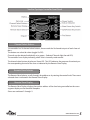
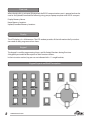
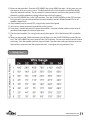
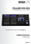
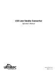
SureFire Pyrologic Digital Controller
Operations Manual
www.ultratecfx.com
VER. 11.07.10
Please Read Carefully Before Operating
Table of Contents
Page 1
Introduction & Warranty
Page 2
Pyro Safety
Page 3Warning
Page 4
Technical Specifications
Page 5
Surefire Pyrologic Controller Front Panel
Page 10
Surefire Pyrologic Controller Rear Panel
Page 11
Channel Select Buttons & Encoder
Page 27 Surefire Digital 16 Channel Slave Module
Page 28
Surefire Digital Airburst Slave Module
Page 29
Surefire Digital Slave Module Addressing
Page 30
Surefire Digital Airburst Slave Module Addressing
Page 30
Pyrologic Controller Surefire Slave Module Safe Field Operation Procedure
Introduction
The Pyrologic Programmable Controller is designed to give the user the ultimate in control flexibility. It is capable of selecting multiple module outputs and fire them simultaneously. You can build a
chase sequence from any module output and vary the speed of the chase. The Pyrologic has 8 Memory Locations, 4 manual shows and 4 time code shows. The programming of this controller is user
friendly. Within minutes you will be programming complex cues and chases.
Warranty
Warranty:
All warranty is one year parts and labour unless specified and is on manufacturer defect only. Abuse, normal wear and tear or poor maintenance is
not accepted. Proof of purchase or proof of sale must always accompany
any warranty returns. A RA (return authorization) number must be noted
on the outside of any box returned to our facilities. Any packages without
a clearly marked RA number will not be accepted by our receiving department. Freight on warranty items are freight prepaid to our facility and we
will prepay freight back to your facility after repair, by the most economical means available. Should you require the item express-returned, then
you are responsible for any difference in freight cost.
Return Policy:
Return of any product must be done within 30 days of purchase. The
package must be returned freight prepaid and the RA number clearly
marked on the outside of the box. A restocking charge of up to 25% may
be levied. Only credits are issued to the dealers account. Any product not
returned within 30 days is considered purchased.
Warning:
Ultratec Special Effects Inc. considers all its product to be safe for use in
the application it was intended. Ultratec Special Effects takes no responsibility for misuse or incorrect use. Always refer to equipment owners
manual for proper use.
**Important Note**:
All defective Pyro Controllers/ Receivers must be returned with an R.M.A.
to Ultratec Special Effects Inc. for corrective actions. Any evidence of
equipment tampering could cause a serious accident and will void the
company warranty.
www.ultratecfx.com
1
Pyro Safety
Safety must be given priority over every other consideration. We recommend that a strict ‘Code of
Practice’ be followed when using pyrotechnics for any purpose. An example ‘Code’ is shown below this is intended as a guide only.
Pyrotechnic special effects can be extremely dangerous and should only be used by competent
adults. Following the manufacturers instructions fully and with extreme care.
1. Eye protection should be used at all times.
2. Always remove the ‘arming’ key and keep it in your pocket at all times. Only put it in the controller
when you are ready to fire the devices.
3. Ensure that suitable fire fighting equipment is at hand and that personnel are trained in its correct
use.
4. Ensure that a suitable first aid kit is available and that personnel are trained in its use.
5. There must be no smoking, exposed flames or any other sources of ignition in the vicinity of pyrotechnic material at any time.
6. All pyrotechnic devices must be located so there is no possibility of injury to people.
7. All pyrotechnic devices must be located so that they cannot set fire to adjacent materials, fabrics,
costumes and scenery etc.
8. The pyrotechnic operator must locate the controller unit, so that he has a direct view of all devices
at all times.
9. Only take sufficient pyrotechnic devices for each performance from the main storage. Do not store
excess material on the stage.
10. One person should be responsible for the setting up of, and the firing of pyrotechnics.
11. Only use the smallest device available to achieve the desired effect. If there are any doubts about
the effect produced, contact the manufacturer for advice before use.
2
www.ultratecfx.com
12. Always consider powering up equipment and continuity testing as actual firing and employ identical safety zones.
13. The use of any pyrotechnics, indoors or outdoors is solely at the discretion of the operator who
will have taken full note of the prevailing situation. Operators are warned that pyrotechnic devices
can sometimes vary in their performance and no guarantee is given by Ultratec that every device will
perform identically - this must be considered when locating devices.
14. Ultratec Pyrotechnics must only be used in conjunction with Ultratec Firing Systems, or Ultratec
approved devices.
No liability of any sort will be entertained by Ultratec where Pyrotechnics are used with unapproved
Firing systems.
Warning
READ THESE IMPORTANT SAFETY INSTRUCTIONS
Do not attempt to operate this unit until the operations manual has been read and fully
understood.
If you have any questions please call Ultratec at 1-800-388-0617
WARNING
READ THESE IMPORTANT SAFETY INSTRUCTIONS
Do not remove the outer case until power has been
disconnected from the machine
www.ultratecfx.com
3
Technical Specifications:
Model:
SureFire Pyrologic Programmable Controller
Type:
Micro-Processor Controlled Low Voltage Firing System
Weight:17 Lbs.
Power Rating:
110 Volt A.C. 50/60 Hz
0.75 Amps
240 Volt A.C.
50/60 Hz
0.35 Amps
SureFire Pyrologic Controller
4
www.ultratecfx.com
SureFire Pyrologic Controller Front Panel
Channel Select Buttons
The controller has 16 channel select buttons, these match the 16 channel outputs of each slave address.
The buttons are select/de-select (toggle On/Off ).
Channels can be selected individually or in groups. (Selected Channels light the red LED).
The controller has a display indicating which slave is currently under control.
The channel select buttons also have a Green LED. This LED indicates the presence of continuity on
the corresponding channel of the slave as indicated by the Remote Slave Display.
Remote Slave Selector
The Remote Slave Selector, scrolls through slave addresses by rotating the control knob. The current
selected slave is indicated in the Remote Slave Display
Remote Slave Display
The Remote Slave Display, displays the number address of the slave being controlled on the seven
segment display on the controller faceplate.
Slaves are numbered 1 through 9.
www.ultratecfx.com
5
Power Switch
Turns On/Off main power.
Safe/Test (Update) /Arm Key Switch
This switch locks out the ability of the controller to fire any slave channels.
The SAFE feature has the dual function of physically disconnecting the FIRE button and disabling the
software command that instructs the slaves to Fire.
When the controller is in the SAFE position. It updates all slave and match continuity in real time.
The ARMED position is indicated by the Red LED ‘On’ in the
Indicator section. This position allows the FIRE button to communicate and disables the status update feature.
Slave Power Key Switch
This switch controls the Firing voltage in all slave modules.
When Slave Power is OFF, the firing voltage is disconnected from the slave modules via an internal
relay. All power available to fire matches is removed.
Since power must be present to test for continuity updates the continuity update feature is disabled
when the Slave Power is OFF.
Slave Power On is indicated by the Green LED ‘On’ in the Status Indicator section.
When Slave Power is ON, the firing current is available to the slave channel outputs.
Fault Indicator Led
The yellow fault LED notifies of a failed output channel on a slave module or a communications error.
Fault status is also indications of the channel firing voltage has been turned OFF. If this is done by
the slave power key switch, the Green LED on the Pyro Logic controller will be OFF.
When the slave power is turned off at the controller, ALL Red LEDs on ALL slave modules will be ON.
If any of the Red LEDs fail to light with the group, the module should be removed from service.
NOTE:Each slave module is equipped with 16 Red fault indicator LEDs. Three sets of 16 in the case of the 48 channel slave.
With the slave power on, a Red LED on the remote slave module will indicate that a channel has
failed and should not be connected to any device. The device may ignite immediately on power up.
6
www.ultratecfx.com
The slave module has a yellow LED indicating ACTIVE FAULT monitoring. This yellow LED is OFF
when a fault is detected and a red channel LED will be on (if it is a short circuit, any device connected
to this channel output will explode immediately).
Slave Power Off
The slave power is required to run the diagnostic routine, therefore when the SLAVE POWER keyswitch is OFF, the system will indicate a FAULT.
Note that when the SLAVE POWER is OFF, all 16 fault indicator (Red) LEDs are ON at all slaves and the
Yellow (Fault Scan) LED is OFF at all slaves.
Slave Power LED
Indicates that slave power is turned on at the controller
Zone Selector
Armed Led
Indicates that the unit is armed at the controller.
Fire Button
Initiates the firing command when depressed.
www.ultratecfx.com
7
Data Link
When the data link is activated (illuminated) the RS232 communications port is opened and can be
used to Set/Upload/Download the following using your pc/laptop computer with RS232 com port.
Display Memory Names
Name Memory Locations
Upload,Download Memory Locations.
Display
The LCD display is 4 x 40 characters. The LCD readout provides all the information the Pyro-technician needs to edit, program and run shows.
Keypad
The keypad is used for programming shows, and for limited functions during Run time.
A Keypad layout and brief description of their functions follows.
In the instruction section, key presses are indicated with >**< angle brackets.
Keypad Layout and Brief Description
8
www.ultratecfx.com
MEM 1 to MEM 4
Memory locations for operator controlled shows
TC 1 to TC 4
Memory locations for operator programmable/Time Code controlled shows. (see MIDI Show Control).
HOME
Returns to the HOME screen. Operator will be prompted to confirm this action. The HOME key functions at the MEMORY SHOW COMPLETE (end of show) screen in Run Mode, and returns to the previous Menu in Edit Mode.
START
Initializes the Mode selection from the HOME screen.
ENTER
Is a command key to enter data or instructions from LCD screen prompts. Save and Exit in Edit Mode.
Starts Edit Mode when prompted at the
Screen..
END CUE
Inserts an ‘E’ to indicate the end of Channel selections for the Cue. Adds next numerical Cue # in
order.
DELETE
Will Delete cue information in reverse order or cancel certain LCD screen prompts. Exit without saving in Edit Mode. Erases memory location when prompted at the
Screen.
CHASE
Inserts the ‘+’ symbol to indicate that a Channel selection, or Groups of Channels, (stages) will be followed by a Delay Time.
DELAY
Calls the Delay Time select screen where the time value of the ‘+’ symbol is determined. (Chase
speed).
VIEW
Flashes the bottom line of the LCD at the current Chase Speed. Review programmed show when
prompted at the
Screen.
UP ARROW
Scrolls LCD display UP Cue to Cue. (9, 8, 7, 6 etc.).Also used at some prompt screens.
www.ultratecfx.com
9
DOWN ARROW
Scrolls LCD display DOWN Cue to Cue. (1, 2, 3, 4, 5, 6...etc.). Also used at some prompt screens.
RIGHT ARROW
Scrolls LCD displayed information Left to Right. For review of Cue data only.
LEFT ARROW
Scrolls LCD displayed information Right to Left. For review of Cue data only.
Match Test/Continuity Update
The Green LED on the channel select buttons of the controller indicates there is continuity at the
channel indicated. Matches on all slaves can be displayed by selecting the slave address on the
module select encoder. This feature will also determine if the expected slave module is On Line. If
the operator expects to see matches on the selected slave and none appear, the slave is not ON Line
or the SAFE/ARMED key is not in SAFE position.
In ARMED mode, match and remote status are not updated, the controller holds the last up date.
To update status, the controller must be switched into SAFE mode (Red control LED OFF) and SLAVE
POWER ‘ON’. (yellow control LED ON).
SureFire Pyrologic Controller Rear Panel
Data Out
The system is connected via a 5-pin XLR communications cable. The communication chain is started
from the 5-pin XLR connector on the rear panel of the SUREFIRE DIGITAL controller.
Pickle Input
There is an XLR connector for an external firing device. (ie. pyro pickle) Pins 1 and 2 are used.
MIDI Pickle Input
There is an XLR connector for an external enabling device. (ie. pyro pickle) Pins 1 and 2 are used.
Used with MIDI Controlled shows
MIDI In
5 Pin Din Connector. Pin Out:
10
www.ultratecfx.com
Little Lite Connector
3 Pin XLR for Little Lite (included) Pins 1 and 3 are used
RS232 Port
Used for Data Transfer form pc or Laptop computer.Female DB9 Connector
Channel Select Buttons and Encoder (Remote Slave Selector).
The Pyrologic Controller has aRotary Slave Selector Knob and two rows of eight select buttons. The
Selector Knob determines the remote slave module address. The 16 channel buttons refer to the 16
remote channels available at each slave address. The following tables show how a channel may appear on the LCD display.
Module Encoder Set to Module 1
101102103104105106107108
109110111112113114115116
Module Encoder Set to Module 2
201202203204205206207208
209210211212213214215216
Module Encoder Set to Module 3
301302303304305306307308
309310311312313314315316
This system of the first digit representing the slave module address and the second 2 digits representing the channel on that slave continues up to the Encoder limit of 9.
Each 16 channel slave address has channels numbered 01 thru 16 on their channel outputs. The
push button encoder on the slave module determines the slave’s current address (first digit of the
channel number).
Note that the standard 48 channel modules are in fact 3 groups of 16 channels and therefore occupy
3 slave module addresses. Each of the 3 addresses are selectable by the user using the push button
encoders on the module.
www.ultratecfx.com
11
Start Up Operation
When the Pyro Logic Controller is powered on, the operator will see the Start up screen.
Start Up Screen
SureFire Pyro Contoller
Press ‘Start’ key to begin
VX.XX
Where X.XX is the code version
The start key is used to continue to the HOME SCREEN.
Home Screen.
*PROGRAM OPERATOR SHOW*
RUN OPERATOR SHOW
PROGRAM TIME CODE SHOW
RUN TIME CODE SHOW
The arrow keys move the * Asterisk * that highlights the current selection.
To chose the * highlighted * function, press >START< (Capitalized words surrounded by the > < refer
to keys on the keypad.).
Programming Operator Shows
To program an Operator Show the SAFE/ARMED switch must be in SAFE position and the Data Link
switch must be off (not illuminated).
At the Home Screen highlight
*PROGRAM OPERATOR SHOW*
press >START< to continue to the Program Operator Show Menu.
Program Operator Show Menu
> OP-1< --- empty --OP-3 --- empty--View-review
OP-2 --- empty --OP-4 --- empty ---
Enter-edit
Delete- erase
OP-1 through OP-4 correspond to Mem.1 through Mem.4 memory locations.
12
www.ultratecfx.com
Using the arrow keys navigate to the memory location (OP-1 through OP-4) to be programmed.
>ENTER< starts edit/program mode. In an empty memory location the screen looks like:
1 -end --- End of Show ---
A cue is the active line in a program. These range from 1-99.
Programming A Single Fire Cue
A Single Fire is defined as a cue where one channel is selected to be Fired.
To select a channel for a Single Fire Cue, turn the numerical encoder (1 to 9) and press a channel button.
The matching numerical channel number is displayed on the LCD in the current cue line.
An -end is automatically inserted to indicate an end to the cue.
To enter this line as Cue # 1 press the down arrow.
Programming A Group Fire Cue
A Group Fire is defined as a cue where all of the channels selected Fire at once.
1.) To select a channel for a Group Fire, turn the numerical encoder (1 to 9) and press a channel button.
The matching Numerical channel number is displayed on the LCD followed by -end.
2.) To accept the channel as part of the Group Fire Cue, press >ENTER< and -end will commence
flashing.
3.) Select another channel for a Group Fire, turn the numerical encoder (1 to 9) and press a channel
button. A > symbol will be displayed as a separator for each channel selected.
Repeat above steps to complete the channel group.
Notes
The Program will only accept 1 channel number at a time.
A channel selection must be followed by >ENTER< .
Channel numbers can be entered in any order (out of sequence).
A sample group channel selection appears as follows
1 208>109>415>211>115>102>711>206E-end
To enter this line as Cue # 1 press the down arrow. The LCD now displays
1 208>109>415>211>115>102>711>206E
2 -end --- End of Show --www.ultratecfx.com
13
If the channel selections are not correct, press the arrow keys to highlight the incorrect entry. Then
press the >DELETE< key. The >DELETE< key will erase a channel number and the symbol (> + or E)
that follows .
Note that channel selections can be duplicated in the same Cue.
If channel selections are repeated in subsequent Cues, the controller will attempt to Fire the repeated channels again as they occur in the show.
Programming A Chase Fire Cue
A Chase Fire Cue is defined as a single channel, or Group of channels, called a ‘Stage’, separated by a
programmed Delay time.
Chase ‘Stages’ are displayed the same as a group fire cue, with the channel numbers separated by
the > symbol.
The DELAY locations are indicated by the the ‘+’ symbol.
The programmed Delay time is inserted at each ‘+’ symbol when the cue program has been completed.
In Run Time, the channel(s) in the first stage of the Chase are Fired at once, (ALL channels preceding
the first ‘+’ symbol).
The program then pauses for the Delay time. (Delay time is selected during programming).
The next Stage of the Chase is Fired after the pause. The sequence continues until the -end symbol
(end of Cue).
During RUN, the FIRE button must be held down for the duration of the chase.
Channel selection is the same as for a Group Fire Cue.
Channels are selected for the first stage of the Chase followed by >ENTER<.
As many channels as desired can be selected for each stage of the Chase and in any order.
To end the first stage of the Chase select the first channel from the second stage and press the
>CHASE< key. The + symbol will appear between the two stages denoting a delay.
Please note that the >CHASE< key will only function after a channel number and Not after the >ENTER< key.
The controller will insert the ‘+’ symbol to indicate that a Delay time will be inserted later in the program.
·
A sample stage selection appears as follows
1__108>609+114>316E-end
·
A multi-stage Chase may appears as in the following example,
1__108>609+114>316>109+101+102+501>116>403+911E-end.
14
www.ultratecfx.com
The programmer is now ready to select the delay time which is inserted at ALL ‘+’ symbols
Press the >DELAY< key.
The Delay screen appears for the previous example as:
1 11 150
Number Cue Steps /
2 -end --- End of Show --- Delay msec
The numbers 1 and 2 signify the cue number. 11signifies the number of channels selected and the
delay time defaults to the minimum Delay time of 150 milliseconds.
The > key will increase the Delay time in 10 millisecond steps.
The < key will decease the Delay time by 10 millisecond steps.
For a real time display of the current chase speed, press the >VIEW< key.
Character blocks flash along the bottom line of the LCD at the current chase speed.
To return to the Cue program screen press >VIEW< again.
To accept the displayed Delay time press >DELAYMS< key.
The Delay time is now inserted at ALL ‘+’ symbol locations.
1__108>609+114>316>109+101+102+501>116>403+911E
The above cue will fire as follows:
108 and 109 will fire, delay, 114 and 316 and 109 will fire, delay, 101 will fire, delay, 102 will fire, delay,
501and 116 and 403 will fire, delay, 911 will fire end cue.
Storing Shows and Editing
A completed show must be stored in memory to be recalled in RUN mode to be fired.
To store an operator show, press the >HOME< key, then the Program Exit Menu appears.
Program Exit Menu:
Halting Edit of Show: OP_1
Enter - Save and Exit
Delete - Exit without saving
Home - Continue Edit
Press >ENTER< key to Save and Exit. (Bring up the Program Operator Show Menu)
Press >DELETE< key to Exit without saving. (Bring up the Program Operator Show Menu)
Press >HOME< Continue edit. (Returns to the show memory location being programmed)
www.ultratecfx.com
15
Editing a programmed memory location can be done at the Program Operator Show Menu by highlighting the memory location and pressing the >ENTER< key to bring up the contents of that memory location.
Use the arrow keys to highlght the cues to be edited. Use the >DELETE< key to remove incorrect
channel.
To add a channel, use the arrow keys to highlight the channel following the channel to be inserted.
Select the channel to be inserted as you normally would using the encoder and channel select buttons.
Run Mode
To recall and run a programmed show,
At the Main Menu select:
*RUN OPERATOR SHOW*
Press >START<
This prompt appears
RUN A PREVIOUSLY PROGRAMMED SHOW
BY RECALLING ANY OF THE OP PROGRAMS
Select the programmed memory keys to be loaded by selecting a key from Mem.1 through Mem.4.
Note that the >TC MEM< keys will not respond in Run Operator Show.
This prompt appears
RUN OPERATOR X MEMORY SHOW
ARE YOU SURE?
PRESS >DELETE< TO CANCEL
PRESS >ENTER< TO CONFIRM
16
www.ultratecfx.com
Pressing >ENTER< will load the selected Show from memory.
The LCD displays Cues 1 to 4 in descending order.
Note that recalling a blank memory location will return the MEMORY SHOW COMPLETE message.
The Operator can return to HOME only from the MEMORY SHOW COMPLETE screen. To return HOME
the operator must use the Arrow key to get to the end of the show before returning HOME. This
feature prevents the unintended aborting of a show by way of an errant or mistaken key press during Run time.
Show Operation
The Cue displayed on the TOP LINE of the LCD screen is always the Cue that will fire when the FIRE
button is pressed.
A Group Fire Cue will Fire all selected channels on the Cue Line at once.
The LCD will scroll all Cues up 1 position. The TOP LINE Cue is uploaded to the slaves.
A Chase Fire Cue will fire the first Stage of channels at once (ALL channels prior to the ‘+’ symbol).
Pause for the programmed Delay Time, then Fire the next Stage of the Chase.
The Chase sequence will continue ONLY if the FIRE button is held down.
Release of the FIRE button during a Chase will halt the Cue
Re-pressing the FIRE button will begin where the Chase halted.
To skip the balance of a Chase Cue in progress, use the ARROW keys to skip the cue.
If the balance of a Chase Cue is skipped and subsequently reloaded to the TOP LINE by the >ARROW< keys, the Chase will Fire from the Beginning of the Cue, NOT from where it was last halted.
Skip a Cue or Review a Show
The UP ARROW and DOWN ARROW keys will scroll through the Cue List in numerical sequence.
*****VERY IMPORTANT*******
The controller will FIRE the CUE displayed on the TOP LINE of the LCD screen.
If using the ARROW keys, be sure that the TOP LINE cue is the correct Cue to be Fired.
The controller will attempt to Fire the TOP LINE Cue even if it has already been Fired
*****VERY IMPORTANT*******
The LEFT and RIGHT ARROW keys will scroll any off-screen channels along the Cue Line.
The LEFT and RIGHT ARROW keys are for review information only. They DO NOT alter the Firing information.
The Controller will Fire a Cue from the Beginning of the Cue, NOT from the LEFT/RIGHT arrow position of the LCD screen.
www.ultratecfx.com
17
Programming Time Code Shows
Time Code Shows are to be recalled in RUN TIME CODE SHOW mode from the Main Menu.
The TIME CODE SHOWs are to be controlled through an external Show Control System.
The Controller has been fitted with a MIDI control circuit board to function with Time Code.
See the section on MIDI Show Control for further details of show control operation.
To program a Time Code Show, the SAFE/ARMED key must be in SAFE position and the Data Link
switch must be off (not illuminated).
When the Pyro Logic Controller is powered on, the operator will see the Start up screen.
Start Up Screen
SureFire Pyro Contoller
Press ‘Start’ key to begin
VX.XX
Where X.XX is the code version
The >START< key is used to continue to the HOME SCREEN.
Home Screen.
PROGRAM OPERATOR SHOW
RUN OPERATOR SHOW
*PROGRAM TIME CODE SHOW*
RUN TIME CODE SHOW
The UP/DOWN arrow keys move the * Asterisk * that highlights the current selection.
To chose the * highlighted * function, press >START< (Capitalized words surrounded by the > < refer
to keys on the keypad.).
At the Home Screen, select
*PROGRAM TIME CODE SHOW*
Press >START< to continue to the Program Operator Show Menu.
18
www.ultratecfx.com
Program Operator Show Menu
> TC-1< --- empty --TC-3 --- empty--View-review
TC-2 --- empty --TC-4 --- empty ---
Enter-edit
Delete- erase
TC-1 through TC-4 correspond to T.C.1 through T.C.4 memory locations.
Using the arrow keys navigate to the memory location (TC-1 through TC-4) to be programmed.
>ENTER< starts edit/program mode. In an empty memory location the screen looks like:
1 -end --- End of Show ---
A Time Code Show is made up of Group Fire Cues ONLY.
A Chase Fire Cue can NOT be activated by MIDI and will NOT be allowed in program time code.
The MIDI Show control will activate and Fire cues in succession to simulate a Chase.
See the MIDI Show Control section for further explanation.
Channel Selection for a Group Fire MIDI Cue
A Group Fire is defined as a cue where all of the channels selected Fire at once.
1.) To select a channel for a Group Fire, turn the numerical encoder (1 to 9) and press a channel button.
The matching Numerical channel number is displayed on the LCD followed by -end.
2.) To accept the channel as part of the Group Fire Cue, press >ENTER< and -end will commence
flashing.
3.) Select another channel for a Group Fire, turn the numerical encoder (1 to 9) and press a channel
button. A > symbol will be displayed as a separator for each channel selected.
Repeat above steps to complete the channel group.
www.ultratecfx.com
19
Notes
The Program will only accept 1 channel number at a time.
A channel selection must be followed by >ENTER< .
Channel numbers can be entered in any order (out of sequence).
A sample group channel selection appears as follows
1 208>109>415>211>115>102>711>206E-end
To enter this line as Cue # 1 press the down arrow. The LCD now displays
1 208>109>415>211>115>102>711>206E
2 -end --- End of Show --If the channel selections are not correct, press the arrow keys to highlight the incorrect entry. Then
press the >DELETE< key. The >DELETE< key will erase a channel number and the symbol (> + or E)
that follows .
Note that channel selections can be duplicated in the same Cue. The program will assemble the
channel list properly during storage.
If channel selections are repeated in subsequent Cues, the controller will attempt to Fire the repeated channels in RUN Mode.
Storing Shows and Editing
A completed show must be stored in memory to be recalled in RUN mode to be fired.
To store an operator show, press the >HOME< key, then the Program Exit Menu appears.
Program Exit Menu:
Halting Edit of Show: TC_1
Enter - Save and Exit
Delete - Exit without saving
Home - Continue Edit
Press >ENTER< key to Save and Exit. (Bring up the Program Operator Show Menu)
Press >DELETE< key to Exit without saving. (Bring up the Program Operator Show Menu)
Press >HOME< Continue edit. (Returns to the show memory location being programmed)
20
www.ultratecfx.com
Editing a programmed memory location can be done at the Program Operator Show Menu by highlighting the memory location and pressing the >ENTER< key to bring up the contents of that memory location.
Use the arrow keys to highlght the cues to be edited. Use the >DELETE< key to remove incorrect
channel.
To add a channel, use the arrow keys to highlight the channel following the channel to be inserted.
Select the channel to be inserted as you normally would using the encoder and channel select buttons.
Time Code Run Mode
To recall and run a programmed show,
At the Main Menu select:
*RUN TIME CODE SHOW*
Press >START<
This prompt appears
RUN A PREVIOUSLY PROGRAMMED SHOW
BY RECALLING ANY OF THE OP PROGRAMS
Select the programmed memory keys to be loaded by selecting a key from T.C.1 through T.C.4.
Note that the >Mem.1< keys will not respond in Run Time Code Show.
This prompt appears
RUN OPERATOR X MEMORY SHOW
ARE YOU SURE?
PRESS >DELETE< TO CANCEL
PRESS >ENTER< TO CONFIRM
Pressing >ENTER< will load the selected Show from memory.
The LCD displays READY FOR TIME CODE.
The Operator can return to HOME only from the MEMORY SHOW COMPLETE screen. To return HOME
the operator must use the Arrow DOWN key to get to the end of the show before returning HOME.
This feature prevents the unintended aborting of a show by way of an errant or mistaken key press
during Run time.
www.ultratecfx.com
21
MIDI Show Control - Time Code Operation
A controller equipped with the MIDI circuit board will respond to the command of an external Show
Control synchronization system. Any system that will generate standard MIDI commands will operate the controller.
A Time Code Show can ONLY be stored to, and recalled from, the four TC MEM location.
The numerical sequence of the Cues is pre-mapped to standard MIDI commands. (NOTE ON).
The MIDI channel commands out of the Show Control System must match the Controller MIDI channel.
MIDI Standards
Since MIDI standards vary from different manufacturers and documentation, the Airburst Controller
MIDI code uses the following conventions;
• There are 128 MIDI notes, lowest to highest.
• The Airburst MIDI control module will number the notes 1 to 128, lowest to highest.
• The 99 available Cues are mapped 1 to 99 to the first 99 MIDI notes, lowest to highest
• There are 16 MIDI channels
• The MIDI controller numbers the channels 1 to 16.
• When synced to an external MIDI Show Control system, MIDI Note On 1 (lowest note) plus the
correct MIDI channel will upload Cue 1 from the Airburst controller to the slaves.
• Cues can be loaded and fired in any order (out of sequence) by sending the corresponding MIDI
Note On command.
• MIDI Notes must include a velocity of Hex 7F
• MIDI note On 127 (second highest) plus the correct MIDI channel, will FIRE the most recent uploaded Cue, displayed on the TOP LINE of the LCD display.
The Cue on the TOP LINE of the LCD is ALWAYS the Cue that will be Fired.
The FIRE command is routed through an external Positive Enable device (Pickle) which must be activated.
Manufacturer Standards
• Some manufacturers use 0 to 127 as the 128 note numbers.
• Some manufacturers use C-2 as the lowest note in music notation
• Some manufacturers use C-0 as the lowest note in musical notation.
• Some manufacturers use 0 to 15 as MIDI channel numbers.
• Be certain of the manufacturer’s standards when programming an external MIDI control device.
The commands must match the Airburst conventions.
Midi Input Data for Firing Control
The MIDI data input consists of a string of serial bits. For Ultratec equipment only basic control data
is required. The unit comes preset to MIDI channel 2. Internal dip switched can be changed to select
channels 2-16. MIDI channel 1 is not available. Typical MIDI devices generate notes from C-2 through
G8. The assignment of the octave designations is not fixed only middle C is defined as data 60 but
could be any octave number.
22
www.ultratecfx.com
The 91 represents a “note on” command on channel 2. The 00 would call for note “C-2” with a velocity
of 7F. Ultratec equipment required the velocity data of (hex 7F) 127. If the data sent was “91 00 7F” a
controller set to channel 2 would load “cue 1”. The cue requested = the decimal value of the note + 1.
Cues 1 - 99 = (hex) 00 - 62.
The fire command is sent as note F# 8 this is hex 7E (126). For a controller on channel 2 the sequence
would be “91 7E 7F”. The fire command fires the active cue and causes the next sequential cue to
load. This would allow the user to fire the show without issuing “load cue” commands if the cues
were suquential. By using sequential firing; cues can be fired at a faster rate than the load - fire method.
Load & FireSequential Fire
91 00 7F
load cue 1
91 07 7F
91 7E 7F
fire cue 1
91 7E 7F
91 4F 7F
load cue 80
91 7E 7F
91 7E 7F
fire cue 80
91 7E 7F
91 2C 7F
load cue 45
91 7E 7F
91 7E 7F
fire cue 45
-2
Octave
load cue 8
fire cue 8
fire cue 9
fire cue 10
fire cue 11
-1
0
1
2
3
4
5
6
7
8
Dec hex
Dec hex
Dec hex
Dec hex
Dec hex
Dec hex
Dec hex
Dec hex
Dec hex
Dec hex
Data
Dec
hex
C
0
0
12
0C
24
18
36
24
48
30
60
3C
72
48
84
54
96
60
108
6C
120
78
C#
1
1
13
0D
25
19
37
25
49
31
61
3D
73
49
85
55
97
61
109
6D
121
79
D
2
2
14
0E
26
1A
38
26
50
32
62
3E
74
4A
86
56
98
62
110
6E
122
7A
D#
3
3
15
0F
27
1B
39
27
51
33
63
3F
75
4B
87
57
99
63
111
6F
123
7B
E
4
4
16
10
28
1C
40
28
52
34
64
40
76
4C
88
58
100
64
112
70
124
7C
F
5
5
17
11
29
1D
41
29
53
35
65
41
77
4D
89
59
101
65
113
71
125
7D
F#
6
9
18
12
30
1E
42
2A
54
36
66
42
78
4E
90
5A
102
66
114
72
126
7E
G
7
6
19
13
31
1F
43
2B
55
37
67
43
79
4F
91
5B
103
67
115
73
127
7F
G#
8
8
20
14
32
20
44
2C
56
38
68
44
80
50
92
5C
104
68
116
74
A
9
9
21
15
33
21
45
2D
57
39
69
45
81
51
93
5D
105
69
117
75
A#
10
0A
22
16
34
22
46
2E
58
3A
70
46
82
52
94
5E
106
6A
118
76
B
11
0B
23
17
35
23
47
2F
59
3B
71
47
83
53
95
5F
107
6B
119
77
www.ultratecfx.com
23
Run a Time Code Show with External MIDI Control
At the Home Screen select
*RUN TIME CODE SHOW*
Press >START<
This prompt appears
RECALL A PRE PROGRAMMED SHOW BY
SELECTING ANY OF THE MEMORY LOCATIONS
When one of the >T.C. MEM< keys is pressed the operator will be prompted to confirm the
choice.
Note that the >MEM< keys will not respond in Run Time Code Show.
RUN TIME CODE SHOW # ?
PRESS >ENTER< TO CONFIRM
PRESS >DELETE< TO CANCEL
Pressing >ENTER< will load the selected Show from memory.
The LCD displays READY FOR TIME CODE
Note that recalling a blank memory location will return the END OF MEMORY SHOW message.
Use the ARROW keys to review the cue information before the Time code is received. The cues
will be displayed One cue per line on all 4 lines.
*****VERY IMPORTANT*******
The controller will FIRE the CUE displayed on the TOP LINE of the LCD screen.
The FIRE button will be LIVE if all the safety features are disengaged. Make certain the controller
is in SAFE mode while reviewing cue information.
The external MIDI Show Control system sends MIDI commands to the Controller through a standard MIDI cable (5-pin DIN).
The controller responds to standard MIDI commands as follows.
MIDI Note On
Note On 1 (lowest MIDI note) will upload Time Code Show Cue#1 to the slaves.
The LCD display will show Cue 1 on the Top Line, followed by the next 3 Cues in numerical order.
Note On 2 (second lowest MIDI note) will upload Cue # 2 etc, with the next three cues in numerical order.
The Cue numbers are directly mapped to MIDI Note On numbers.
The Airburst controller will respond to the MIDI Note On commands in any order.
24
www.ultratecfx.com
The LCD displays the Cue number called for by the show control on the TOP Line, followed by the
next 3 cues in numerical sequence.
The TOP LINE of the LCD will always be the Cue that will be fired.
MIDI Note On 127 (second Highest) is the Fire Command.
This Fire Command is routed through an external Positive Enable switch.
Should the operator release the positive enable and abort the Fire command, the FIRE button on the
controller will still be live and available for manual fire if desired.
·Example
Live performers have not cleared their marks. The Cue is aborted. (not fired by show control).
The performers are then cleared and the Operator wants to Fire the Cue Manually.
He must do so before a new Cue command (MIDI note on #) is received by the controller.
The Cue on the TOP LINE of the LCD is ALWAYS the Cue that will Fire.
An uploaded Cue (TOP LINE of LCD) is replaced by a new Cue whenever a new MIDI Note On command is received, regardless of the previous Cue being Fired or not.
For example - The controller receives MIDI note on 2 and uploads Cue # 2.(TOP LINE of LCD).
The operator releases the Positive Enable after Cue 2 has been uploaded to the remotes.
When the FIRE command is received (MIDI note on 127) Cue 2 will NOT Fire.
10 seconds later the controller receives MIDI Note On 4.
The controller will replace Cue 2 with Cue 4 (TOP LINE of LCD) and upload Cue 4 data to the
remotes.
When the Fire command (Note On 127) is received, (positive enable ON), Cue 4 Fires.
MIDI Channel
The Airburst controller can be set to respond to any ONE of the 16 MIDI channels.
Be sure the MIDI channel of the controller matches the MIDI channel sent by the external MIDI show
control device.
If the channels do not match, the Airburst controller will not respond.
Multiple Airburst controllers can be used in the same production by addressing the controllers to different MIDI channels.
ALL other MIDI commands are ignored by the Airburst controller.
SMPTE and MIDI Timing
SMPTE
Many Show Control systems derive their timing from SMPTE time code information. This information
is then translated into MIDI commands. SMPTE time code is divided into Hours-Minutes-SecondsFrames
The Frame rate is selectable. The two most common frames rates are described below.
Frames is the smallest unit of time in SMPTE code and concerns the Airburst controller communication timing as follows.
www.ultratecfx.com
25
The Airburst controller needs a certain (Very short) amount of time to communicate with the slaves.
Therefore the controller needs to have time to upload firing information to the slaves before they can
be fired. The minimum timing set out in the Airburst system is 150 milliseconds.
If SMPTE time code is used as the source and the rate of the SMPTE code is 30 frames per second, one
frame is equal to 33 milliseconds. It will be necessary to upload a cue to the slaves a minimum of 25
frames prior to the Fire command being engaged. Sequential firing can occur with 5 frames between
events.
If SMPTE time code is used as the source and the rate of the SMPTE code is 24 frames per second, one
frame is equal to 41 milliseconds.
It will be necessary to upload a cue to the slaves a minimum of 20 frames prior to the Fire command
being engaged. Sequential firing can occur with 4 frames between events.
MIDI
The time code set out by a MIDI controller is dependant on the tempo of the music. Since the tempo
can be varied greatly from passage to passage, there is no simple formula to calculate the timing
requirements as with SMPTE.
The Show Control programmer will have to be responsible for ensuring that the minimum real time
required by the Airburst controller between Cue upload and Fire (150 milliseconds) is not compromised.
26
www.ultratecfx.com
SureFire Digital 16 Channel Slave Module
The SureFire Digital Slave Module has 16 channel output connections, a status monitor section, a
soft-power On/Off keyswitch, an Address Encoder and two 5 pin XLR data connectors on the front
panel.
Channel Outputs
The SureFire Digital 16 Channel Slave Module
is equipped with standard 3 pin XLR connectors. Alternate connectors and configurations
can be specially
ordered.
Power Keyswitch
The keyswitch shuts down all operating power from the slave unit without the need to access the
main power switch on the rear panel. The key can be removed in the ‘Off’ position for safety.
Slave Address Encoder
This push button encoder is used to set the address of the slave from 1 to 9 (‘0’ is an invalid slave address and does NOT correspond to ‘0’ on the controller display).
The slave must be powered Off then On for the encoder change to be in effect (power On / Off key).
The slave address corresponds to the Slave Select Encoder on the controller.
(See the Slave Module Addressing section for further details).
Status Monitor LEDs
The Green LED indicates power is ‘On’.
The Yellow LED indicates That the fault scan is active and there are no faults.
The 16 Red LED’s indicate a channel at fault. Remove slave from service until repaired.
Notes
1. Since Firing a channel is similar to a short circuit, the Red LED will flash as it’s channel is fired. This
is a normal condition and can be used to test show configuration and channel activity without
connecting a match or other indicator.
Since an open circuit is also a fault, in the case where the slave power has been turned ‘Off’ at the
controller, all 16 Red LED’s will be ‘On’ since they will all report open circuit (no power).
www.ultratecfx.com
27
Data In / Data Out
These are the communications connectors (5 pin XLR). Data In is Male, Data Out is Female.
Slaves can be daisy chained in any order on the data line, however the connections must run Out to
In to Out to In etc. The data signal is rebroadcast at each remote to improve performance and distance.
SureFire Digital Airburst Slave Module
The 48 channel Digital Airburst Slave has 16 output connections, a status monitor section, a softpower On/Off keyswitch and two 5 pin XLR data connectors on the front panel.
Channel Outputs
The Digital Airburst Slave is equipped with standard RJ style phone connectors (6 pin). Each connector has 3 circuits grouped (1&2), (3&4), (5&6).
Power Keyswitch
The keyswitch shuts down all operating power from the slave unit without the need to access the
main power switch on the rear panel. The key can be removed in the ‘Off’ position for safety.
Slave Address Encoder
48 Channel Slave Modules have encoders mounted on the back panel. The encoders should be set
to occupy 3 consecutive numbers (ie. 123 or 234, etc).
Status Monitor LEDs
The Digital Airburst Slave integrates 3 separate DS-16 circuit boards and monitors the status of each
board on a separate LED section.
The 3 Green LED indicates power is ‘On’ for each board..
The 3 Yellow LED indicates that the fault scan is active and there are no faults at each board.
The 48 Red LED’s indicate a channel at fault. Ensure that nothing is connected to this channel output
until the fault has been corrected.
Notes
1. Since Firing a channel is similar to a short circuit, the Red LED will flash as it’s channel is fired. This
is a normal condition and can be used to test show configuration and channel activity without
connecting a match or other indicator.
2. Since an open circuit is also a fault, in the case where the slave power has been turned ‘Off’ at the
controller, all 48 Red LED’s will be ‘On’ since they will all report open circuit (no power).
28
www.ultratecfx.com
Data In / Data Out
These are the communications connectors (5 pin XLR). Data In is Male, Data Out is Female.
Slaves can be daisy chained in any order on the data line, however the connections must run Out to
In to Out to In etc. The data signal is rebroadcast at each remote to improve performance and distance.
SureFire Digital Slave Module Addressing
16 channel Slave modules have a push-button Encoder on the front panel.
The Encoder sets the slave module address
from 1 to 9.
The zero ‘0’ address is invalid.
The 16 channel slave Encoder/Channel number tables are the same as the channel select
numbers on the controller.
For Example
A 16-channel slave with the Encoder set to
address ‘5’, co-responds directly to the Digital Controller Encoder setting ‘5’.
Channel select buttons 1 to 16 and slave channel outputs 1 to 16 will then correspond.
Important Note
CAUTION!!!
The slave must be powered down for a change to the Encoder address to take effect.
If it is not powered OFF it will remain at it’s old address regardless of Encoder setting.
Important Note
Slave Modules CANNOT share the same address.
For Example
Two slaves with the same address will NOT operate in symmetry, they will return an error.
www.ultratecfx.com
29
SureFire Digital Airburst Slave Module Addressing
Important Note
Airburst 48 channel slave modules should occupy 3 consecutive Encoder numbers. This is selectable
by the encoders.
48-channel Airburst slaves and 16-channel slaves can be configured to run from the same controller
so long as there is no address conflict.
Pyro Logic Controller SureFire Slave Module Safe Field Operation Procedure
Read and familiarize yourself with the operators manuals for these products. If there is something
you do not understand about the addressing and operation of the SureFire system, consult qualified
personnel.
DO NOT connect ANY pyro devices to the system prior to running the following steps. You run the
risk of injury or death to yourself and your co-workers.
1. Place all slave modules in position. The system is designed for modules to be placed in close
proximity to the pyrotechnic effects to avoid long runs of cable from the channel outputs to the
pyro effects or matches.
2. In the case of regular effects, keep the modules at least six feet from the effect. Dust and debris
from these effects may effect the operation of the slave modules over the long term.
3. In the case of ‘concussion’ effects, place the modules at least 15 feet from the concussion pots.
The shock from the concussions can damage the electronics of the module and/or shake the
communication or AC connections loose.
4. Run all communication and AC cables to the modules.
5. Set up the PyroLogic controller.
6. Plug all communication cables into the controller.
7. With the SAFE/ARM key in the SAFE position and the SLAVE POWER key in the OFF position, recall
the show you intend to run.
8. All slaves should be powered on and all 16 Red channel LEDs should be lit. The Green Power LED
should be lit. The Yellow scan LED should NOT be lit. (See Trouble Shooting).
9. From the controller, identify all on line modules by turning the encoder. On-line modules will
show all 16 green match LEDs lit when the module select knob is turned to the address of the
module.
10.Turn the SLAVE POWER key switch ‘ON’. Firing and match test current is now applied to all module
output channels. This test confirms communication between the controller and all slave modules.
11.Investigate each slave for faults. All 16 Red channel LEDs should be off. (If there are any Red
channel LEDs still lit, see trouble shooting). The Green Power LED and the Yellow scan LED should
be lit. (See Trouble Shooting).
30
www.ultratecfx.com
12.Return to the controller. Place the SAFE/ARMED key in the ARMED position. At this point you can
fire some or all of your cues as a test. The Red channel LEDs of the modules should flash briefly
when the modules are fired. This test confirms communications and shows the operator which
channels on which modules are firing without the use of test matches.
13.Turn the SAFE/ARMED key to the SAFE position. Turn the SLAVE POWER key to the ‘OFF’ position.
Firing current is now disconnected from the slave modules and all 16 Red channel LEDs on all
modules should be lit.
14.Slave modules can be turned ‘OFF’ using the key on the front panel.
15.You are now ready to connect pyro devices to the system.
16.Once pyro is connected you must restart the modules. Sound an all clear and be certain that all
personnel and property are clear of pyro areas.
17.Turn the slave modules ‘On’ using the key on the front panel. All 16 Red channel LEDs should be
lit.
18.Return to the console. While maintaining the all clear, turn the SLAVE POWER key to the ON position. The SAFE/ARMED key must remain in the SAFE position. You are now ready to test for match
continuity. Turn the encoder (and use the port select if you have the multi-port option) to ensure
that matches are present on their proper channels. Investigate missing matches if any.
Wiring Chart
www.ultratecfx.com
31