1
Training Guide
DVR-65H-S / DVR-520H-S
DVR-320-S / DVR-225-S
DVR-220-S
Technical Training Department
1925 East Dominguez Street
Long Beach, CA 90810
Contents
Overview
4
Model Number Setting
26
Block Diagrams
5~9
Disc Download Procedure
27~28
Recording Block
6~7
Service Modes
29~51
Preview Block
8~9
Service Mode Screens
29~35
Overall Board Layout
10
Error Codes
36~39
Main Board
11~12
Key Codes
40~42
HDD Unit
13
Simple DV Diagnosis
43
Overall Block Diagrams
14~17
Error Rate Measurements
44~45
System Configuration
15
Channel Setting Mode
46~49
Complete Block
16~17
Aging Modes
50~51
Adjustments & Data Setting Modes
18~52
Start-Up Sequence
52
Tuner & Main PCB Adjustments
19~20
Disassembly Section
53~58
Service Diagnosis List
21
LSI_NG & Flash_NG Diagnosis
60~66
CPRM ID Number & Data Setting
22~25
HDD Diagnosis Method
68~74
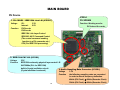
Overview
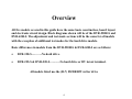
All five models covered in this guide have the same basic construction, board layout
and electronic circuit design. Block diagrams shown will be of the DVR-520H-S and
DVR-65H-S. The adjustment and test mode sections will be the same for all models
with the exception of additional test modes for the hard drive models.
Basic differences in models from the DVR-520H-S & DVR-65H-S are as follows:
•
DVR-320-S………..No hard drive.
•
DVR-225-S & DVR-220-S………..No hard drive or DV in/out terminal.
All models listed use the (R-7) DVDR/RW writer drive
4
Block Diagrams
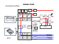
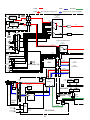
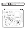
SIGNAL FLOW
DEC
SDRAM
64Mb
ENC
SDRAM
128Mb
ATA
SDRAM
256Mb
Tuner & Line Input Recording
1394 Link
DV-codec
1394
Phy.
SRC
Frame
TBC
3D Y/C
Video
ADC
DVD-R/RW Drive
Stereo
Decoder
Video
AV-Enc.
DNR
(REC)
PAL/NTSC
Decoder
Input
Selector
Audio
A/D
ATA I/F
AV-codec
LSI
M65672WG
TV
Tuner
Audio
Line-In
Select
CPU
SDRAM
128Mb
32bit RISC
CPU
Hard Disk Drive
FLASH
64Mb
Tuner/FL
Control CPU
Backup
SRAM
4Mb
AV-Dec.
3D DNR
(PB)
Video
DAC
Y/C/CVBS Video Out
Y/Cb/Cr Video Out
INPUT
OUTPUT
Graphics
Engine
Progressive
Converter
PAL/NTSC
Encoder
Audio
D/A
Audio Analog Out
DIF Out (Opt.)
6
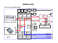
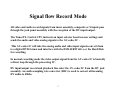
Signal flow Record Mode
All video and audio record signals from tuner assembly, composite or S inputs pass
through the jack panel assembly with the exception of the DV input/output.
The Tuner/FL Control CPU instructs an input selector based on user settings and
sends the audio and video analog signals to the AV-codec IC .
This AV-codec IC will take the analog audio and video input signals convert them
to a digital DVD format and interface with the DVD-R/RW drive or the Hard Disk
for recording.
In normal recording mode the video output signal from the AV-codec IC is basically
a direct loop through the processing IC.
DV input/output record and playback line enter the AV-codec IC from the DV jack
assembly. An audio sampling rate converter (SRC) is used to convert all incoming
DV audio to 48khz.
7
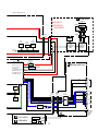
SIGNAL FLOW
DEC
SDRAM
64Mb
ENC
SDRAM
128Mb
ATA
SDRAM
256Mb
Recording Preview Mode
1394 Link
DV-codec
1394
Phy.
SRC
Frame
TBC
3D Y/C
Video
ADC
DVD-R/RW Drive
Stereo
Decoder
Video
AV-Enc.
DNR
(REC)
PAL/NTSC
Decoder
Input
Selector
Audio
A/D
ATA I/F
AV-codec
LSI
M65672WG
TV
Tuner
Audio
Line-In
Select
CPU
SDRAM
128Mb
32bit RISC
CPU
Hard Disk Drive
FLASH
64Mb
Tuner/FL
Control CPU
Backup
SRAM
4Mb
AV-Dec.
3D DNR
(PB)
Video
DAC
Y/C/CVBS Video Out
Y/Cb/Cr Video Out
INPUT
OUTPUT
Graphics
Engine
Progressive
Converter
PAL/NTSC
Encoder
Audio
D/A
Audio Analog Out
DIF Out (Opt.)
8
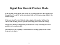
Signal flow Record Preview Mode
In the normal viewing mode (non record) or recording modes the video signal passes
through the AV-codec IC on the main board with very little processing visible at the
monitor output.
If the user selects Preview Mode the video output at the monitor will show the
effects of all encoding, 3D Y/C separation, decoding and record mode settings.
This preview mode was designed to provide the user a way of viewing the record
quality prior to making a disc.
All models have the capability to select different recording quality based on time
from one to six hours.
9
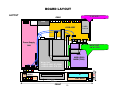
BOARD LAYOUT
LAYOUT
TUNB ASSY
REAR
FAN
TUNER
FrontFront-end
JCKB ASSY
Power Supply
Unit
MAIN ASSY
(under HDD)
HDD
80GB (520H)
160GB (720H)
FL
FRJB ASSY
FLKY ASSY
8mm space
420mm
FRONT
10
59mm
mm
69 Æ 59
Writer Unit
ÆDRIVE ASSY R7 (520H)
ÆDRIVE ASSY R7R (320)
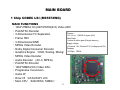
MAIN BOARD
1 Chip CODEC LSI (M65672WG)
MAIN FUNCTIONS
・ 10bit*27MHz(1ch),8bit*27MHz(3ch) Video ADC
・ PAL/NTSC Decoder
Process
・ 3-Dimensional YC Separation
Æ 0.13μm、CMOS 6 Layers (6Cu)
Gate Scale
・ Frame TBC
Æ about 4 million gate (Except memory)
・ 3-Dimensional DNR
Supply voltage
・ MPEG Video Encoder
Æ Internal 1.2V, External 3.3V (Voltage-proof 5V)
Package
・ Dolby Digital Consumer Encoder
Æ 576pin PBGA
・ Graphics Engine (OSD, Scaling, Mixing)
・ MPEG Video Decoder
・ Audio Decoder (AC-3, MPEG)
・ PAL/NTSC Encoder
・ 10bit*54MHz(5ch) Video DAC
・ Progressive Conversion
・ Audio I/F
・ Drive I/F(ATA/ATAPI, 2ch)
・ Main CPU (32bit RISC, 54MHz)
11
MAIN BOARD
DV Device
1. DV CODEC / IEEE1394 Link LSI (IC5202)
Voltage
I/O:
3.3V
Internal:
2.5V
Function
DV Decode
DV Encode
IEEE1394 Link Layer Control
IEC61883 AV/C Command Control
(The control command sending
function to a DV camcorder etc.)
CPU (For IEEE1394 processing)
IC5204
DV SDRAM
Function: Working area for
DV link and the codec
2. IEEE1394 PHY LSI (IC5101)
Voltage
3.3V
Function
IEEE1394 conformity physical layer control LSI
24.576MHz (PLL for IEEE1394)
built-in Crystal oscillation circuit
3. Audio Sampling Rate Converter (IC3301)
(Crystal oscillator is external)
Voltage
3.3V
Function
the following sampling rates are converted
in order to absorb frequency deflection.
48kHz (DV Clock) Æ 48kHz (Recorder Clock)
32kHz (DV Clock) Æ 48kHz (Recorder Clock)
12
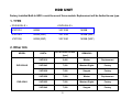
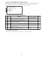
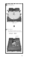
HDD UNIT
Factory Installed Built-In HDD’s could be one of three models. Replacement will be limited to one type.
1. TYPE
< DVR-520H-S >
< DVR-65H-S >
VXF1010
80GB
VXF1028
160GB
VXF1043
80GB (NSP)
VXF1055
160GB (NSP)
VXF1036
80GB (NSP)
VXF1040
160GB (NSP)
2. Other Info
MODEL
DVR-520H-S
DVR-65H-S
PART#
ROTATIONAL SPEED
[rpm]
REMARKS
VXF1010
5,400
Maxtor
Replacement
VXF1043
7,200
Western Digital
Factory
VXF1036
7,200
Seagate
Factory
VXF1028
7,200
Maxtor
Replacement
VXF1055
7,200
Western Digital
Factory
VXF1040
7,200
Seagate
Factory
13
Overall Block
Diagrams
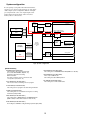
System configuration
In each signal-processing LSI of the main function blocks,
various processes have been integrated into one chip, which
enables simpler system configuration. With the AV-signalprocessing LSI at the center, video inputs/outputs, audio
inputs/outputs, DV inputs/outputs, writer and various
memory cells are connected to it.
UPD72893BGD-LML
UPD72852AGB-8EU
IC5202
1394 Link /
DV Codec
1394 (DV)
IC5101
1394 Phy
IC3301
SRC
IC1102
Flash
DVR-520H-S , DVR-320-S & DVR-65H-S
IC1103
SRAM
IC3101
Audio A/D
AK5357VT
IC1101, IC1201, IC1301
IC1401 SDRAM
Record
HDD
FL
CVBS/YC/YCbCr
IC3201
Audio D/A
Playback
Tuner / Line
Select
IC202
Tuner / FL
Control
CPU
IC1001
AV Signal
Processing
LSI
Playback
Drive Assy
(DVD-R/RW)
Video : IC701 LA73033
Audio : IC601 LC75342M
Analog Audio
PCM1742KE
Record
DIF
DVR-520H-S
Fig2. System configuration
[Memorized Data]
• EEPROM (IC204 JCKB ASSY)
The information about Tuner is backed up.
(Pre-set CH, AFT ON/OFF, Skip CH, etc)
Information about timed recording
Other information
(The state of Volume, remote control mode and
last positions (Line/Tuner, etc)
• CPU SDRAM (IC1101 MAIN ASSY)
The execution area and working area of a program
• ATA SDRAM (IC1401 MAIN ASSY)
The working area of ATA/OSD2/Audio TBC (OSD2 is for all GUI.)
• ATA SDRAM (IC1421 MAIN ASSY)
This is only for HDD model.
The working area about HDD operation.
• DV SDRAM (IC5204 MAIN ASSY)
The working area of Link and DV Codec
• FLASH ROM (IC1102 MAIN ASSY)
The storing area of a program code and setting information
• SRAM (IC1103 MAIN ASSY)
The working area for record and the storing area of setting
information (backup RAM)
• DEC SDRAM (IC1201 MAIN ASSY)
The working area of MPEG playback and OSD/Thumbnail
(OSD is mainly for Disc Menu creation in Video mode)
• ENC SDRAM (IC1301 MAIN ASSY)
The working area of MPEG recording and analog input and output (AVIO)
15
Audio
Video
U301 VXF1022
TV FRONT-END
ANT
RF IN
RF AOUT VOUT
19
OUT 16
A
TUNB
ASSY
17
3
MPX
Decoder
Video Selector
Video Driver
IC701
LA73033(1/2)
UVV
(19P)
(19P)
UVV
2V
UVL
L
LPF
OUT 21
7 MPX Audio
IN
7
7
UVL
1V
3V
CN451
CN402
(13P)
(13P)
1Y
2Y
17
15
13
6 CIN2 8
LPF
77
75
7
1C
(15P)
V/Y
V/Y
79
3C
CN1301 CN705
F
19
27
3Y
ATT WIDEBAND SPECTRAL
(15P)
: Playback system signal route Video
: Recording system signal route
CN401
CN301
IC451 CXA2020M
CD Audio
Audio
5
2C
C
25
C
LPF
3
FRJB
ASSY
JA1301
4
Y
YIN2
10
Audio Selector with Electirc ATT
IC601
LC75342M
Y/C
C
JA1302
LIN4
VIDEO
8
L
VIN2
11
6
13
R
12
LIN2
14
2
L
5
12
INPUT3
INPUT1 JA601
VIDEO
LIN2
LIN1
LIN3
VIN1
VIN3
Y
CN4501
Y/C
L
YIN1
R
YIN3
B 1/3
INPUT3
VIDEO
Y/C
[ATA]
HDD
IC1001
M65673WG
JCKB ASSY(1/3)
CIN1
Y
(40P)
DVR-520H-S
C
1 Chip
System Codec
CIN3
C
[ATAPI]
1
LIN1
L
LIN3
R
DVD-VR
DVD-Video
8
IC202
SDRAM
16Mbit
CN101
4
B
C
D
S4
S3
S2
S1
PICKUP
ASSY
201
Writer
CPU
C
48
MAIN ASSY
33
34
35
38
PB DVD/CD
37
40
7-10
13-16
STEPPIONG
MOTOR
M
CPU SDRAM
128Mbit
IC1101
ASSY
B 2/3 JCKB
(2/3)
76
CD Digital
13
39
IC101
UPC3330GC
2
CN703 (2P)
2
(12P)
CD Digital
CN201
IC501
BD7907FS
DRIVE ASSY
16
13
(21P)
(21P)
CN501
CN502
CN3001
(1/2)
CN702
(1/2)
RF IC
(2P)
M
Flash
64Mbit
IC1102
36
6CH
Driver
LOADING
MOTOR
SRAM
4Mbit
IC1401 ATA SDRAM
256Mbit ×2
IC1421
IC301
M30700FKLGP
2
A
(40P)
IC201
UPD63630GM
3
LD
DRIVE
(40P)
IC1103
5
Pickup
CN401 CN4401
DSP
(45P)
SPDL
MOTOR
DVD-VR
DVD-Video
• R ch is same as L ch.
J
DVJB ASSY
TPB
XTPA
TPA
JA1401
XTPB
DV TERMINAL
DVR-65H-S
DVR-520H-S
DVR-320-S
1
2
3
4
1,3 2
6
7
CN5102 1,3 2
CN701(1/2)
(32P)
SEL.V/Y
9
IC202
PEG034A
IC204
BR24L32F-W
Tuner
U-com
EEPROM
9
SEL.C
7
IC203
RS5C372A
Real
Time
Clock
IC5204
DV SDRAM
16Mbit
(7P)
6
XTPB
TPB
XTPA
(7P)
TPA
CN1401
7
7
38 39 37 36
IC5202
UPD72893BGD-LML
IEEE1394
Link IC
IC5101
UPD72852AGB-8EU
IEEE1394
Physical IC
Control
Data
L
SEL.L
5
5
CN2001
(32P)
IC3101
AK5357VT
Master Clock Freerun
B 3/3 JCKB ASSY(3/3)
Sampling Rate IC3301
SM5950AM
Converter
C IN
CVBS IN
JA701
AG24
AF23
AD21
AG25
AE24
Y(G)
Y(G)
Cb
F5
Cb
D2
IC1301
ENC
SDRAM
128Mbit
Cr
Cr
JA702
VIDEO
VOUT
CN2001
(2/2)
(32P)
Cr/R
DEC
SDRAM
128Mbit
IC1201
Cb/B
Y/G
Y
C
CN701
(2/2)
21
21
23
23
25
25
29
29
27
27
Cr OUT
Cb OUT
Y(G) OUT
Y OUT
C OUT
51
60
53
56
45
58
43
63
41
65
IC3201
PCM1742KE
1-3
2
Audio 7
D/A Conv.
1
3
17
17
1
KIRB ASSY
FL
Y
C
CN1001
(19P)
17
R
COUT
VIDEO
LOUT
Y
C
LINE
OUT 2
R
1
(19P)
Key
SW
Cr
JA651
CN201
FL Driver
V1001
Cb
L
Tuner U-com
IC1001 PT6315
LINE
OUT 1
L
L OUT
(21P) (21P)
FLKY ASSY
Y
C
Y(G)
68 V
IC3251-1/2 CN3001(2/2) CN702(2/2)
UPC4570G2
SPDIF
D
E
YOUT
IC701
LA73033(2/2)
(32P)
COMPONENT
VIDEO OUT
• MPEG2 PS Encode
• AC-3/Linear PCM
Audio Encode
• 2ch ATA/ATAPI Interface
• MPEG2 PS Decode
T26
• AC-3/MPEG1/Linear
V27
PCM Audio Decode
9 Audio
10
A/D 2
12 48KHz
20Bit
OPTICAL
AC-3/PCM
DIGITAL
AUDIO
OUT
Adjustments
Test Modes
&
Service Modes
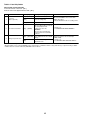
No.
* It is not necessary to adjust the ASSY normaly when exchanging the ASSY. But the adjustment is
necessary when exchanging the Tuner Module and IC451 stereo decoder IC.
Adjustment Name
Adj. Point Measurement Point Adjustment Value
Adjustment State
Input a signal of Mono 1kHz/100% modulation
to terrestrial tuner input. /through output.
1
Stereo Decoder ATT adjustment
(Input system adjustment)
VR453
Audio ouput (L)
(Rear panel)
2
Stereo Decoder Wideband
adjustment (Input system adjustment)
VR451
Audio ouputs (L/R)
(Rear panel)
Input a signal of Stereo 300Hz/30% modulation
Best point of separation
(NR-ON/L ch only) to terrestrial tuner input.
≥30dB Note 1
Note 2
3
Stereo Decoder Spectral adjustment
(Input system adjustment).
VR452
Audio ouputs (L/R)
(Rear panel)
Best point of separation Input a signal of Stereo 3kHz/30% modulation
(NR-ON) to terrestrial wave input. /through output
≥25dB Note 1
Note 2
370mVrms ± 18.5mV
Note 1 : The values for channel separation is defined as those having passed through the following filters :
100Hz – 10kHz : +0/–0.5dB
15.75kHz – 100kHz : -40dB or more
Note 2 : The adjustment No.2 and No.3 should be repeated 2 times for good adjustment.
(Steps : No.1 → No.2 →No.3 →No.2 →No.3)
TUNB ASSY
TUNB
VR451
VR453
C451
VR452
C453
VNP1963-A
G-Link
U301
C467
V+9
KN300
C462
SEPA
R328
LF
VWV
L303
C461
Q451
E B C2
1 1
Fig.1 Adjustment Points (TUNB ASSY)
CN451
R467
R466
C465
ICT FC
R468
C473
C456
19
19
C474
R471
C472
R307
R306
NP
L306
CN301
C326
C327
V+9
C471
D301
19
C B2 E2
C458
R463
C460
GND
Q304
C303
R326
1
VR453
R318
R324
R312
V+5TU
R301
C304
Q302
C468
C459
R455
PYKC F4X
C318
PC
R453
R454
R
GND
Q306
C313
Q301
R317
R316
JA301
C328 or R325
C302
C309
D302
2
C301
C319
1
4
C316
3
R315
5
C306
C305
C329
SEPA
ADJAST
ADJAST
VR452
VR451
SPECTRUM WIDE
NP
INPUT
LAVEL
ADJAST
13
13
* It is not necessary to adjust the ASSY normaly when exchanging the ASSY, but confirm the data.
Adj. Point Measurement Point
Master clock free-running adjustment
(Clock system adjustment)
MAIN ASSY
IC3402 Pin8 (XTO)
(SM8707KV)
VC4201
CN4401
8
2
8
2
R5219
8
2
R5221
8
1
7
R4407
7 1
R4408
2
7 R4406 1 7 R4405 1
8
2
8
2
8 2
8 2
7 1
1
2
1
7
8
2
2 8
8
L5507
C5206
TP5204
R5244
R5239
2
8
1
R4507
R4508
7
2
1 7
C4020
R4501 R4503
8
CN4501
IC3301
2
R4509
8
R5240
C5329
C5205
C5208
R5241
R5243
R5246
C4401
R4504
C5223
12
13
1
2
R1008
R4436
156 157
1
7
1 7
TP3303
C5230
R5294
7 1
L1006
1
CN4001
C4029
R4018
8
TP4005
C4023
R4014
C4024
F4001
8 R4538 2
R4017
R4020
C3406
R4001
C4018
C4006
R2017
R2019
TP4002
Q2001
C4021
TP4009
TP41
TP3003 TP3001 TP3014
TP3012
TP3002
TP42
TP3004
R4004
R4008
R4015
R4009
F3102
TP3006
TP3005
C4010
R4541
TP4001
TP4010
C4027
C4005
TP4012
IC4005
8
7
1
7
TP3401
C3405
C3407
F3403
R3410
R3408
R3202
TP3402
C4004
Q3202
R3205
TP3007
C4028
R3411
F3401
C3301
10
C3004
TP3008
1
TP3010
TP3009
R4534
D4501
R4010
3
TP4011
Q3201
IC3001
11
C3403
R3405
R3406
C3408
C3404
8
C3101
C3105
1
TP2017
IC4008
TP4201
R3203 R3204
IC4003
TP3403
IC3402 Pin8
IC4004
1
C3102
20
TP3013
TP3011
C3001
R3002
TP2025
R2015
R2026
R2014
TP2014 TP2024
R2013
R4019
D4001
8
F3402
C4013
C3002
1
4
5
D3002
R4530
R4537
C3402
C4014
TP4008
R3103
D3104
D3102
D3101
C3106
9
16
IC3402
4
R4531
C5221
R5297
5
IC3403
1
D3001
R5298
R3407
C5224
R3409
R3001
20
L5508
C5229
C3303
R3403
C5231
1
24
C1040
9
IC3101
R3104
D3103
R3025
R3024
R3023
R3022
R3003
C3251
TP2023
R2012
R5293
C5222
C3302
L3301
16
1
R3105
TP2013
TP2016
R3271
R2011
7
C5321
C1059
C1058
C1053
3
R4201
4
R4204
C4210
R3108
R3107
L4202
TP2012
TP2011
R3270
TP2008
R2047
1
8
C3255
TP2009
TP2006
TP2005
TP2004 R2027
7
R4510
R3309
R3102
R2254
Q2241
R2253
R2255
R5250
R5255
1
R4432
R4435
R3304
R3313
R3305
R3106
C2405
TP2021
Q2402
TP2001 R2412
TP2019
TP2002
R2405
TP2022
8
2
7
C5211
7 1
2 8
R5248
R5258
R5245
R5242
8
C5213
R5295
R5261
R5296
1
C3108
TP2007
C2243
7
2
8
C5218
8
8 2
C5225
2
8
2
52
C1050
1
1
R1003
L1001
C1042
R1074
TP1013
TP1012
X4201
R4210
C4202
C4201
F4201
IC4205
8
1
104
2
R5259
C3107
5
D4202
4
C4208
D4201
105
53
R3311
R3312
R3306
2 C4211
TP1029
R5275
2
1
R5273
7
2 8
1
8
7
7 R5274 1
R5132
R5131
TP5106
C1060
L1007
C1036
C1038
R1004
L1003
R1005 C1035
L1004
R4205
L4201
C4209
C4203
R4209
C2406
R2025
R2040
C5209
7 R5220 1 7 R5218 1
C5120
R1009
C1041
C1037
L1005
C1055
C1030
C1029
C1056
C1026
C1024
TP1028
R4207 R4208
TP2020
C5210
R5121
R5123
C5119
C5118
C1003
C1510
C1004
C1034
R1006
Q2102
Q2103
TP1027
TP1032
R4202
C4206
5
4
8
4
R2404
R2411
C5123
R5124
R5112
R5113
C1509
C1028 C1002
C1014
R1090
C1016
C1025
C1001
TP1060
VR1001
VR1002
R1011 TP1051
Q2104
C1027 C1508
L1009
R1012
R2112
R2109
C2105
Q2105
R2102
8
C2210
IC4206
C4207
5
IC2302
1
TP2505
TP2503
TP2504
TP2502
1
3
R5283
R4428
R4429
R5313
R5314
R3307
TP4202
7
R5230
C2241
R2406
TP2506
R2407
Q2403
7 C2311
1
R2306
8
R2502
R2408
TP2501
2
C2407
R2409
7 1
71
TP1030
8
R1045
R5281
R5282
IC5204
VC4201
VC4201
R5225
R3310
C1039
R5222
R5224
R1031
C1049
R2227
R5236
R5227
R5228
R5229
R3303
C1006
R5234
R5235
C5228
R5278
R5279
R5280
R1066 C1051
R5223
R4211
R4206 R4212
C2302
C2305
8
1
R2308
C2308
IC2301
TP48
Q2101
C1013
R1080
C2220
C2223
R1905
C1047
R5217
R5238
R5284
R5285
5
1
4
1
TP2018
4
5
TP50
C2103 R2103
C2104
C2102
C2331
R2334
C2332
R2214
R1043
R1048
R4213
3
R2331
R2332 R2208
R2305
1
4
IC2331
C2334
7
6
C2333
R2333
R1904
R1901
R1903
R1902
C2206
C2221
C2208
R2204
C2201
Q2204
8 2
82
2
R5289
C1045
C1048
R5215
C5227
C1044
TP1033
TP1024
R2209
R5232
R5214
R5237
R5286
R5277
R5287
R5288
TP38
TP31
TP5201 R5216
C5226
R5276
C1052
C1021
TP1026
TP1031
IC5202
C5217
C1057
C1005
R2239
C2205
Q2203
CN1901
R5265
R2221
R2205
TP4301 TP4303
TP49
C1012
TP2003
C2202
R2203
TP4302
C1019
C2101
TP32
C5207
R5231
R5233
C5215
R5290
R1034
Q2222
IC2211
2
R4304
R5127
C5113
C1022
C2222
R2210
R5130
64
C1018
R2111
L5504
R5272
1
C1023
R2207
1
2 8
R2304
R2206
1 7
2 8
R2301
Q2301
R2307
Q2202
1 7
TP15
C2306
2
TP5202
C5126
C1017
C2209
C2204
R4303
R2302
R2303
7
Q2201
R4302
C2106
Q2311
R2312
C2301
1
2 8
C5216
TP1002
R2106
R2105
1 7
8
R5128
R5129
16
48
R2233
R2235
TP4307
TP4306
TP4305
TP4304
R2313
CN4301
8
R2252
Q2302
R4306
7 1
C2246
Q2312
R2202 R2201
7
R2266
R2311
R2314
R4307
TP14
1
R2115
7
2
IC5101
C1031
C1032 R1021 R1022
TP1050
R1023
TP1041
R2116 R2114 R1024
R2113
C2319
C2317
8
C5111
R5104
1
2 8
1
C5103
C5127
17
49
R2107
8
C4104
C4103
R4101
TP28
C2265
2
R5105
R1071
VR2105
L1102
8
R4110
IC4101
5
4
R4103
R4107
R4305
R5106
C1054
VR2104
R4104
R4106
C5105
C5110
C1011
C4102
3
2
L1008
R4108
C4105
R4102
X4102
4
C4106
1
R4109 C4107
R1052
R5126
C5125
R4105 R1111 C1114
Q1102
R5125
33
TP2015
D1111
C1061
R5107
R5247
1 7
8
C5104
7
C5138
X5101
32
R5103
R5249
7
208
7
C5137
C5204
C5214
L5502
C5212
C5124
C5122
F4003
R5108
C5136
L5106
R5115
R5117
R5110
IC4007
L5105
C5112
L5104
L5101
L5102
L5501
C5102
C4033
C5132
L5103
R5109
7
C5101
C4032
C4034
1
TP1067
No signal input
R5251
R5252
C5121
R5263
R5262
R5260
R5257
R5256
R5253
R5254
F5101
TP4015
C1104
27.000000MHZ
± 130Hz
SIDE A
D4002
2
Adjustment State
MAIN ASSY
CN5102
1
Adjustment Value
C4031
C
1
1
Adjustment Name
R5114
R5116
R5120
R5122
No.
TP40
Service Diagnosis List
CPRM ID NUMBER AND DATA SETTING
The Setting is necessary
• " CPRM ERR" is displayed on the FL display immediately after the power is turned on or in Stop mode.
• When the MAIN ASSY , DRIVE ASSY or the FLASH ROM is exchanged.
MODEL SETTING
DOWNLOAD METHOD
The Setting is necessary
• When the MAIN ASSY is replaced.
• When the JCKB ASSY is replaced.
• When the MAIN ASSY and JCKB ASSY is replaced.
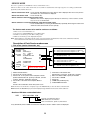
SERVICE MODE
[First Screeen] (Version information, etc)
[Sub Screen 1] (Result of error-rate measurement : Video mode/VR mode)
[Sub Screen 2] (HDD information)
[Second Screen] (ATA/ATAPI debug screen)
[Sub Screen 3] (writer maintenance information of ATA/ATAPI DEBUG OSD)
[Sub Screen 4] (ATA/ATAPI DEBUG OSD_LD degradation judgement)
[Fourth Screen] (VR-recording error log)
[Sub Screen 4] (Error log for VR recording)
[Fifth Screen] (Error log for VR playback)
[Sub Screen 2] (Error log for VR playback)
DV DEBUG MODE
[Third Screeen] (DV debug information)
ERROR RATE MEASUREMENT
Only Video mode measurement
VIDEO ADJUSTMENT FOR SPECIFIC AREA
Purposes:
Depending on the area, jitter may appear in a picture received by the tuner, as conditions of signals received by
the tuner are different from area to area. To correct this kind of problem, the function of the System Codec AVIO
control section for adjusting signals received by the tuner can be used.
AGING MODE
21
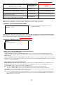
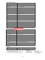
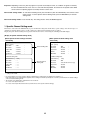
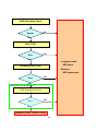
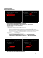
CPRM ID NUMBER AND DATA SETTING
Entering the ID Number and ID Data for DVD Recorder
For the DVD recorder,it is necessary with the recoding/playback of DVD–RW disc to set an individual number (ID number) and ID data to
each recorder. If the number and data are not set correctly with the following procedure, operations in the future may not be guaranteed.
You will find the ID number to be set on the ID label on the rear panel.
Important: If no ID label is found on the rear panel, write down the specified ID number by checking it according to "How to
confirm the ID number" shown below.
The Input is Necessary When:
• " CPRM ERR" is displayed on the FL display immediately after the power is turned on or in Stop mode.
• When the MAIN ASSY , DRIVE ASSY or the HDD is exchanged.
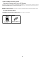
JIGS AND MEASURING INSTRUMENTS
Service Remote Control
Unit (GGF1381)
DVD Recorder Data Disc
(GGV1179) (*) Refer to P138.
22
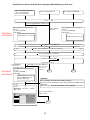
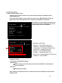
Input Flow of the ID No. and ID data when exchanging HDD, MAIN Assy or Drive Assy
• When exchanging HDD or MAIN
Assy, or both exchanged
• When exchanging HDD
When displayed "CPRM ERR"
When exchanging Drive Assy
Power →
ON
Also exchanging DRIVE Assy simultaneously
DVR-65H-S
DVR-520H-S
When displayed following message at
Power on
FL Tube : [HDD ERR]
CRT display :
Only exchanging
Drive Assy
When displayed following message at
Power on
FL Tube : [CPRM ERR]
CRT display :
HDD information is not correct.
CPRM information is not correct.
Confirmation of the CPRM ID No.
Deletion of the CPRM ID No.(when ID No. is registered.)
Input of the CPRM ID No. and ID data
Power →
OFF →
ON
Normal operation mode
New HDD/when
there is error
on recorded contents
DVR-65H-S
DVR-520H-S
Exchanging to the original HDD(when
there is no error on
the recorded
When displayed following message at
contents.)
End
Power on
FL Tube : [HDD ERR]
CRT display :
HDD information is not correct.
Execute HDD Initialize from
the Disc Setup menu.
*Use Remote Control of
the model
Execute
HOME MENU → Disc Setup → Intialize
HDD → Start
Basic
Initialize
Finalize
Initialize HDD
[CAUTION]
All recorded data are deleted if the HDD is intialized.
Take care that restoration of the user's data recorded on the HDD is totally
impossible.
Before servicing, OBTAIN THE USER'S PRIOR CONSENT to that effect.
*Goes to normal operation
with no caution
Disc Setup
Initialize
End
Start
End
23
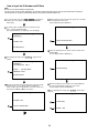
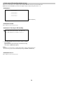
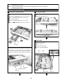
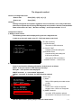
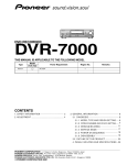
How to Input the ID Number and ID Data
Note:
Be sure to enter the ID number in Stop mode.
Use the service remote control (GGF1381) for operations. Only opening/closing of the tray are performed from the player.
The ID data disc is swept out automatically after the recorder has read the data from it.
1 To enter the input mode, press ESC + STEREO sequentially in
a status with no ID number set, such as after FLASH-ROM
downloading.
5 While the data are being read, the message shown in the figure
at left is displayed on the screen.
(The FL display indicates "LOAD ID.")
[Recorder's ID Data Setting]
2 As number input is enabled when the unit enters the input
mode, input the 9-digit ID number.
(The entered number is also displayed on the FL display.)
2
[Recorder's ID Number Setting]
ID Number ?
>--------<CLEAR> Exit
5
Loading The ID Data Disc !
Input ID Number !
6 When the ID data have been read, the data are written to the
FLASH-ROM.
(The FL display indicates "WRITE ID.")
3 After inputting the number, press SEARCH to register the ID
number.
[Recorder's ID Data Setting]
[Recorder's ID Number Setting]
ID Number ?
> 0 0 0 0 0 0 0 0 1 OK ?
3
6
<PLAY>
Compare Mode
<SEARCH> Enter
Wait Rom Writing !
Input ID Number !
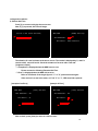
4 When the ID number has been registered, the unit enters the ID
data input mode. (The FL display indicates "INSERT ID.")
In this condition, place the ID data disc on the tray and close the
tray using the CLOSE key "7/0" on the player.
[Recorder's ID Data Setting]
7 When the ID data have been written to the FLASH-ROM, the
message "Rom Write OK" is displayed on the screen.
(The FL display indicates "ID DATA OK.")
8 After confirming this message, press CLEAR to exit the input
mode.
[Recorder's ID Data Setting]
<CLEAR> Exit
4
7
Rom Write OK !
8
<CLEAR> Exit
Insert The ID Data Disc !
24
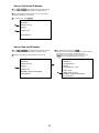
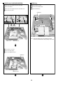
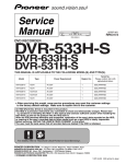
How to Confirm the ID Number
1 Press ESC + STEREO sequentially with an ID number already
set, and the unit enters the ID number confirmation mode.
2 The set ID number is displayed on the screen (and on the FL
display), permitting you to confirm it.
3 To exit this mode, press CLEAR .
2
3
[Recorder's ID Number Setting]
ID Number ?
[ 0 0 0 0 0 0 0 0 1]
Compare
>*********
<CLEAR> Exit
Input ID Number !
How to Clear the ID Number
1 Press ESC + STEREO sequentially with an ID number already
set, and the unit enters the ID number confirmation mode.
2 Input the same number as the ID number you have set.
2
[Recorder's ID Number Setting]
ID Number ?
[ 0 0 0 0 0 0 0 0 1]
Compare
>*********
<CLEAR> Exit
<STEREO> ID Data Setting Mode
Input ID Number !
3 After inputting the number, press STOP .
Only when the entered number matches the set ID number, the
ID number is cleared and the unit exits this mode.
If the numbers do not match, you must return to step 2.
( STOP is not accepted until 9 digits are entered.)
[Recorder's ID Number Setting]
ID Number ?
[ 0 0 0 0 0 0 0 0 1]
Compare
> 0 0 0 0 0 0 0 0 1 OK ?
3
25
<PLAY> Enter
<STOP> Memory Clear
<STEREO> ID Data Setting Mode
Input ID Number !
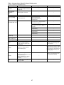
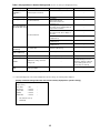
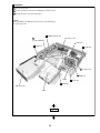
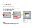
MODEL SETTING
• The Setup is Necessary When :
a) When the MAIN Assy is replaced
b) When the JCKB Assy is replaced
c) When the MAIN Assy and JCKB Assy are replaced
Note : Make sure of setting the correct number.
• How to Setup the Model
1) After power on, the following screen is displayed on TV monitor.
Press " 22 " by using the remote control unit for service(GGF1381).
[ Recorder 's Model Setting]
Input the number by using the remote for Service.
Note: Press '29" for DVR-220-S
Press "26" for DVR-225-S
> -Input No.
[
22
[
23
Model
: DVR-520H-S
: DVR-65H-S
Press "21" for DVR-320-S
]
]
2) After 1), the following screen is displayed on TV monitor.
Press " 011 " by using the remote control unit for service.
[ Recorder 's Type Setting]
Input the number by using the remote for Service.
> ---
(Type -- , Region No. -)
Input No.
[
01
:
Type
KU/CA
<US>
]
The setting complete when OSD is disappeared.
3) Unplug the power cable.
4) Reset the recorder to all its factory settings.
1. Make sure that the recorder is on.
2. Press and hold [STOP] and press [STANDBY/ON] key on the front panel.
The recorder turns off with all settings reset.
5) Enter the Service Mode and then confirm the Model Name " DVR-520H/KU/CA ".
1. Make sure that the recorder is on.
2. Press [ESC] then [DISP] keys by using the remote control unit for Service.
DVR-520H/KU/CA
VERSION : 0.60
SYSCON : RELEASE_45
Rev
:1.3685 $
TUFLCON : 1.22 MASK
DRIVE : DVD-RW DVR-107X
1.10K
CKT0000353WL
HDD
DEVICE
REGION
C
FLASH
:
:
:
:
:
ST380012ACE
PRISM-PLUS
1
∗∗∗∗∗∗∗∗∗
64M
OK
OK
OK
OK
80
Notes :
1) After the setting complete, you can NOT CLEAR the seting data.
Make sure the pressing number.
2) " NG " is appeared on TV when unsuitable number is pressed.
In such a case, please unplug the power cable and plug it again. Then restart the model setting.
26
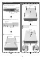
DOWNLOAD METHOD
• The Download is Necessary When :
a) After model setting
b) When "NG" is displayed at First screen (version information, etc)
[Notes]
Be sure NOT to turn off the unit during downloading.
If the unit is turned off during downloading, the SYSCON, TUFLCON, and DRIVE programs may not be properly rewritten, in
which case the unit may not be able to initialize itself normally when turned on again. If that happens, repair the unit, as
described below, then perform downloading again:
• In a case where the power to the unit was shut off during rewriting of the SYSCON program:
The SYSCON program will not function properly if the power to the unit is forcibly shut off while the message "DOWNLOAD1" is displayed on the FL display during downloading. If downloading of the programs from the disc or through serial
communication becomes impossible, replace the FLASH ROM.
• In a case where the power to the unit was shut off during rewriting of the DRIVE program:
The DRIVE program will not function properly if the power to the unit is forcibly shut off while the message "DOWNLOAD-2" is
displayed on the FL display during downloading. If downloading of the programs from the disc or through serial
communication becomes impossible, replace the DRIVE ASSY.
• In a case where the power to the unit was shut off during rewriting of the TUFLCON program (only for the flash-type
TUFLCON microcomputers):
The TUFLCON program will not function properly if the power to the unit is forcibly shut off while the message "DOWNLOAD3" is displayed on the FL display during downloading. If downloading of the programs from the disc or through serial
communication becomes impossible, replace the TUFLCON microcomputer.
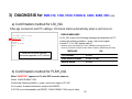
1. DISC DOWNLOAD METHOD
• How to Download
This is disc download method to save the initial setting data and user setting data.
However, the following data is deleted after downloading by this method.
* Disc history data
* REC mode
* Last channel (Before turn unit off)
1) Open a disc tray in the " DVD " function.
2) Put the download disc on the tray.
3) Press and hold a " STOP " button for playback,
then press a " DISC NAVIGATOR " button on a front panel.
- The disc tray closes automatically and the disc is loaded.
- The disc tray opens automatically after loading.
4) Take out the Download Disc.
- " DISC DWLD " is displayed on FL and download is started.
- The display on FL changes to " DOWNLOAD-1 "
- The display on FL changes to " DOWNLOAD-2 "
- The display on FL changes to " DOWNLOAD-3 " (*)
- After download is completed, the power turns off, and turns on and a disc tray closes automatically.
* It takes for about 5 minutes until download is completed.
5) Press and hold a " ESC ", then press " DISP " on a test mode remote control unit for the release version confirmation.
6) Confirm a firmware release version.
7) Press " ESC " on a test mode remote control unit in order to exit the test mode.
(*) : " DOWNLOAD-3" is displayed only when the TuFL u-com is FLASH type.
27
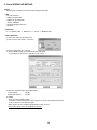
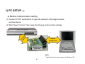
2. Serial DOWNLOAD METHOD
[Notes]
This method is secondary way when the disc loading is impossible.
• JIGS
* PC with serial port
* RS232C straight cable
* RS232C I/F jig (GGF1348)
* 7P FFC (VDA1681)
* Download program (UFU.exe)
* Firmware
• Connection
PC ⇔ RS232C cable ⇔ RS232C I/F ⇔ 7P FFC ⇔ DVD Recorder
• How to Download
1) Connect the 232C I/F JIGS above way.
2) Turn on the PC and start the " UFU.exe ".
.
3) Select the Firmware file. ("sz0" file)
4) Turn the DVD recorder on and start the download program.
" Target Device is connected" is appeared on the screen.
.
5) Select the Communication Speed (Baud Rate)
a) Base Speed
38,400
b) Data Send Speed
115,200
6) START
* Even if you click "START" button,
sometimes "Communication Error" may come out one to twice, and download may fail.
In this case, please click "START" again.
* Other factors can be considerd if download fails 3 times or more.
* And it takes about an hour for updating the firmware.
28
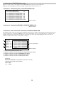
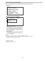
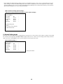
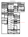
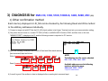
SERVICE MODE
For service operations, use the GGF1381 remote control unit for service.
The Service-mode screens consist of nine mode screens, which are classified into such rough categories as recording system and VR
playback system, and their subscreens.
• How to enter Service mode : Press the ESC then DISP keys in turn while no GUI is displayed. The first screen (version
information, etc.) shown below is displayed.
• How to exit Service mode : Press the ESC key.
• How to advance to the next Service-mode screen
: While the first screen is displayed, press directly one of the keys 1-9. For service, use the
keys 2, 4 or 5, as shown below.
• How to advance to a subscreen within the same Service-mode screen
: Press the DIG/ANA key. Pressing the DIG/ANA key repeatedly will change the subscreens
within the same Service-mode screen cyclically.
The Service-mode screens to be used for service are as follows:
1 = First screen: Version information, etc.
2 = Second screen: ATA/ATAPI debug screen (Writer data)
4 = Fourth screen: Error log for the VR recording system
5 = Fifth screen: Error log for the VR playback system
Note: After entering one of the Service-mode screens, if you wish to shift to another Service-mode screen, exit Service mode first,
then reenter Service mode and select your desired Service-mode screen.
Description of Each Service-mode screen
1. First screen (version information, etc.)
1
2
3
4
5
6
7
8
9
10
DVR-520H/KU/CA
VERSION : 0.60
SYSCON : RELEASE_45
Rev
:1.3685 $
TUFLCON : 1.22 MASK
DRIVE : DVD-RW DVR-107X
1.10K
CKT0000353WL
HDD
DEVICE
REGION
C
FLASH
:
:
:
:
:
ST380012ACE
PRISM-PLUS
1
∗∗∗∗∗∗∗∗∗
64M
OK : OK (proper combination)
NG+ : Version of the tuner microcomputer too advanced
(*1)
NG– : Version of the tuner microcomputer too old
OK
NG
OK
OK
OK
OK
: OK (proper drive)
: NG (improper drive) (*2)
OK : OK (proper combination)
NG+ : Version of the drive too advanced
(*3)
NG– : Version of the drive too old
80
OK
NG
: Serial No. of the drive already registered
: Serial No. of the drive not registered (*4)
32M For all other models
(*1–*4 : Refer to two pages after.)
1 Model name/destination
2 Version of the recorder software
3 Revision No. of the system-control computer software
(Edition administration No. [from top to bottom, common
software, firmware, application software])
4 Version No. of the tuner microcomputer, Mask or
Flash
Result of the combination ckeck with system u-com
5 Information on the built-in drive
(Model name, version No., model type, serial No.)
6 Data of the built-in HDD, capacity of the HDD
7 Version No. of PRISM
8 Region No.
9 CPRM data (CPRM key No.)
0 FLASH ROM information
While the first screen shown above is displayed, press the DIG/ANA key to enter the subscreen shown below.
Note: Each time the DIG/ANA key is pressed, the display changes between the first screen and its subscreen.
• Details on HDD data are described below:
HDD
:
WDC10234564 # 80
Capacity of the HDD (unit: Gbytes)
HDD identification error indication
Name of manufacturer, part No. by manufacturer
If any abnormality exists in HDD connection, the indications shown in Table 1 below are displayed.
29
Table 1: HDD data indications according to various HDD connection statuses
HDD identification conditions
DVR-65H-S & DVR-520H-S
Example of HDD data
to be displayed
Remarks
Failure in physical identification of HDD
(no connection, defective HDD, interface error)
Blank space
Physical identification of HDD possible, but not identified
WDC 10234564 # 80
"#" is displayed as HDD identification error
Physical identification of HDD possible, HDD identified,
but failure in logical formatting
WDC 10234564 ! 80
"!" is displayed as HDD identification error
Physical identification of HDD possible, HDD identified,
and correct logical formatting (HDD correctly identified)
WDC 10234564 80
While the first screen shown above is displayed, press the DIG/ANA key to enter the subscreen shown below.
Note: Each time the DIG/ANA key is pressed, the display changes between the first screen and its subscreen.
• Subscreen 1: Result of error-rate measurement
ERR RATE
: x.xe-x/
Note: Be sure to start playback after displaying this subscreen
to calculate the error rate.
During playback in VR mode, the average error rate of the past 10 VOBUs is displayed, and during playback in DVD-Video or
Video mode, the average error rate of the past 256 sectors is displayed. During playback in VR mode, the rotation rate of the
drive (/: normal speed, no display = double speed) is also displayed.
• Subscreen 2: HDD information DVR-65H-S & DVR-520H-S
HDD Info
Life Time: 87599h 09m 05s
Cumulative HDD-on time
• How the data on cumulative HDD-on time are processed in memory
Storage place: Backup SRAM, Flash ROM
Timing of referring to the data on cumulative HDD-on time: When the power is turned on, the backup SRAM is referred to
regarding the data on cumulative HDD-on time, and the data are stored in the RAM. If referring to the backup SRAM fails, the flash
ROM is referred to.
Timing of updating the data on cumulative HDD-on time: While the HDD is on, the data on cumulative HDD-on time in the RAM
is updated every 3 seconds, and every time updating is executed the data are stored in the backup SRAM. When the power is turned off,
the data are stored in the flash ROM.
How to clear the data on cumulative HDD-on time
Backup SRAM: When the HDD Identification Setting is performed, the data on cumulative HDD-on time are automatically cleared.
The HDD Identification Setting is automatically performed when the CPRM setting is performed on the CPRM setting screen (to
display the CPRM setting screen, press the ESC then the STEREO keys).
Notes: The data on cumulative HDD-on time are not cleared when resetting to factory-preset values is performed.
The data on cumulative HDD-on time are not cleared when the system-control computer software is downloaded.
Flash ROM: The data on cumulative HDD-on time cannot be cleared (they are not cleared even if resetting to factory-preset values is
performed or if the system-control computer software is downloaded).
Note: The data on cumulative HDD-on time in the flash ROM can be cleared if you clear the data in the backup SRAM following the
above-mentioned procedures then turn off the power of the unit, because the data in the backup SRAM are stored in the flash
ROM when the power is turned off.
30
• When "NG" is displayed at First screen (version information, etc)
(*1) NG+ : Version of the tuner microcomputer too advanced
NG- : Version of the tuner microcomputer too old
1. When TUFL µ-com is MASK type
NG+ : Download the firmware.
NG- : Replace the TUFL µ-com or JCKB ASSY.
2. When TuFL µ-com is FLASH type
NG+ : Download the firmware.
NG- : Download the firmware.
(*2) NG : NG (improper drive)
Replace the correct Drive Assy.
(*3) NG+ : Version of the drive too advanced
NG- : Version of the drive too old
NG+ : Download the firmware.
NG- : Download the firmware.
(*4) NG : Serial No. of the drive not registered
Check the part No. and replace the correct Drive Assy.
31
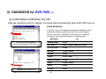
2. Second screen (ATA/ATAPI debug screen)
Subscreen 1 of the second screen is displayed when the ESC, DISP, then "2" keys are pressed, in that order.
Note: Each time the DIG/ANA key is pressed, the display changes cyclically among subscreens 1 to 4.
• Subscreen 1: Command log (ALL) of ATA/ATAPI DEBUG OSD
A T A / A T A P I History - ALL
32 010000000000A000
OK
32 2A00000DEBB000063000
OK
32 2A00000DF1E000063000
OK
32 2A00000DF81000063000
OK
32 2A00000DFE4000062000
OK
32 2A00000E046000063000
OK
32 2A00000E0A9000063000
OK
32 2A00000E10C000063000
OK
>32 2A00000E16F00006200023A00
(Not for Service)
• Subscreen 2: Command log (ERROR) of ATA/ATAPI DEBUG OSD
(Not for Service)
• Subscreen 3: Writer mentenance information of ATA/ATAPI DEBUG OSD
The cumulative power-on time and error log that are administered by the writer are displayed. Such information is obtained when the power
is turned on. Thereafter, each time the SEARCH key on the remote control unit for service is pressed while subscreen 3 is displayed, the
updating command is sent, and the data on the subscreen are updated. Care must be taken when updating this subscreen, because an
undesired command is inserted if it is executed while recording, etc.
1
2
3
4
5
1
2
3
4
5
ATA/ATAPI
Power ON
0102:56
DVD
R0053:48
W0022:16
CD
R0034:04
W0000:00
Writer MaintenanceInfo
00 00 00 0000 00000000
01 00 00 0000 00000000
02 00 00 0000 00000000
03 00 00 0000 00000000
04 00 00 0000 00000000
05 00 00 0000 00000000
06 00 00 0000 00000000
07 00 00 0000 00000000
0 0- 0 0
Error log for the Writer
(Not for Service)
Power-on time/cumulative power-on time
Duration of emission of the laser diode (LD) for DVD-R/DVD while reading
Duration of emission of the LD for DVD-W/DVD while writing
Duration of emission of the LD for CD-R/CD while reading
Duration of emission of the LD for CD-W/CD while writing
(Reference)
MTTF time of each LD (as the guideline of life span of each LD)
R7R Drive Assy (Read + Write total time)
DVD : 4700h
CD : 11000h
32
• Subscreen 4: ATA/ATAPI DEBUG OSD_LD degradation judgment
The degrees of degradation of the LD (laser diode) for the writer (LDs for CD and DVD separately), temperature, and RF level are
displayed. To update the data on the subscreen, press the SEARCH key on the remote control unit for service while subscreen 4 is
displayed. See Table 1 below for a description of each item and the conditions for updating data.
A T A / A T A P I - LD Degrade
CD
DVD
TMP
ADJ
RF
TLT
1
2
3
4
5
6
:0070
:0068
:00A3
: 0 0 67
:3D70
:FFD5
104%
96%
4 1 °C
2 6 °C
OK
OK
Table 1: Description of each item and conditions for updating data
No.
Item
Conditions for updating by
pressing the SEARCH key
Description
Remarks
1
CD
Degradation judgment of LD for CD. Regarded as NG when the value
No disc inserted in the disc tray
is 120% or higher (same standard as for the PC drive)
∗1
2
DVD
Degradation judgment of LD for DVD. Regarded as NG when the
value is 120% or higher (same standard as for the PC drive)
No disc inserted in the disc tray
∗1
3
TMP
Current temperature inside the Writer
No disc inserted in the disc tray
∗1
4
ADJ
Temperature (approx. 25°C) inside the Writer during adjustment
No disc inserted in the disc tray
∗1
5
RF
RF level (16-bit data, proportional calculation performed using the
actual RF level value with 2.5 V = 0xFFFF as the maximum value,
displayed in 4-digit hexadecimal)
During playback of disc medium
∗2
6
TLT
Writer adjustment data for straight (non-HDD) model
(FFFF is diplayed when the writer is not adjusted.)
No condition
∗1 : For correct judgment, after leaving the unit at a normal temperature (25°C typ.) for some time, judgment must be performed immediately
after the unit is turned on with no disc loaded.
∗2 : Use this item only for confirmation before and after lens cleaning, as the lens becomes dirty with dust.
33
3. Fouth screen (VR-recording-related error log)
Subscreen 1 of the fourth screen is displayed when the ESC, DISP, then "4" keys are pressed, in that order.
Note: Each time the DIG/ANA key is pressed, the display changes cyclically among subscreens 1 to 11.
• Subscreen 1:
RunFnc : ---- Ecl : **** Rate : **
-------------------------------------------------------------------------------------------------------------------------------
(Not for Service)
• Subscreens 2 and 3:
These subscreens are not for service use.
• Subscreen 4: Error log for VR recording
1
Recording Error History Display
01–06–01 20:05:30 No SysHdr IN
01–06–02 00:22:10 Write Error
1 Recording-related error log for the last 18 errors, divided
into 2 screens
(generation time [year-month-day, hour:minute:second],
error data in simplified description)
Notes:
• For details on error messages, see Table 2 "Description of VR-recording-related errors".
• The two error-log screens can be switched by pressing the SPEED+ or SPEED- key.
• Subscreens 5 to 11:
These subscreens are not for service use.
34
4. Fifth screen (Error log for VR playback)
Subscreen 1 of the fifth screen is displayed when the ESC, DISP, then "5" keys are pressed, in that order.
Note: Each time the DIG/ANA key is pressed, the display changes cyclically among subscreens 1 to 4.
• Subscreen 1:
G : 001–01 00h00m00s00# –. – e – – 00 . 00M
Tgt : STOP Now : STOP Spd : 0
Man : STOP Sub : 0 VBF : 000 ABF : 00
TrMd : STOP TrSt : 0 TNo : Ver : 00
RvMd : STOP RvSt : 0 DNo : Aer : 00
CcSt : STOP
ld : 00000000
Stc : 00000000 Tpp-Av1 : +-0 V-A : +-0
MPEG2 720x480 A0 AC-3 2ch 0256k
NT ASP : 43 CGMS : 0 APS : 0 Src : 0
END : 00h00m00s00
Cell : 000
• Subscreen 2: Error log for VR playback
1
2
G : 01–01 00m00s# –. – e – – 00000000
h m s Message
h m s Err
G001 : 000000 Tr : N u l l b l k
L002 : 001230 Tr : S c h L a t e
L002 : 004103 Tp : V o b D i f +
L002 : 004104 Tp : V o b D o f –
1 Data on location of the display
Original(G)/play list (L), title No., chapter No. (X:XX-XX),
time of the display (min, sec, frame [XXmXXsXX]), busy
mark of the virtual mechanical-control computer (#),
error rate of the transfer data (X.XeXX), playback logical
address (ID [XXXXXXXX])
2 Error message log
Original(G)/play list (L), title No., time of generation (min,
sec [XXX:XXXX]), playback-related error log for the last
13 errors (XX:XXXXXXX)
Notes:
• For details on error messages, see Table 1 "Description of VR-playback-related errors".
• If a VR-playback-related error is generated, a problem in data reading from the disc may be suspected.
(The possibility of a problem on the drive side is high.)
• Subscreens 3 and 4:
These subscreens are not for service use.
35
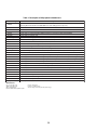
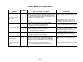
Table 1: Description of VR-playback-related errors
Error Message
Tr : NullBlk
Description
Transfer task: NULL at the top block
(Detecting NG stream made at the DVR-1000 series and starting protection process.)
Tr : ReadErr
Transfer task: ATA read error
Tr : SchLate
Transfer task: ATA search late
Tr : SemTOvr
Transfer task: Timeout for gaining semaphore (no synchronization with the display)
Tr : NaviErr
Transfer task: Inconsistency between NAVI (navigator) of management data and actual NAVI
Tr : OrderEr
Transfer task: Inconsistent order
Mn : Av1Hang
Main task: Detects hang-up of AV decoder and starts recovery
ERR_RCV!
TPP task: Detects hang-up of AV decoder and starts recovery
Tp : VobDif+
TPP task: The decoder STC advances by 1 VOBU hour.
Tp : VobDif-
TPP task: The STC of the management information advances
Tp : midNULL
TPP task: The management information pointer designated was NULL.
Tp : ScanNg
TPP task: Failure to set the TPP memory when scanning was canceled.
Tp : RStepEr
TPP task: Although the reverse step had failed, the operation was forcibly terminated because the top cell was located.
Tp : tppErr
TPP task: Inconsistency occurred.
Rv : 1stTOvr
Reverse playback task: Timeout for waiting for interruption to the top VOBU immediately after starting decoding
Rv : OpnTOvr
Reverse playback task: Timeout for waiting for B-picture of the open GOP immediately after starting decoding
Rv : OplTOvr
Reverse playback task: Timeout for waiting for I-picture of the open GOP immediately after starting decoding
Rv : LnkTOvr
Reverse playback task: Timeout for waiting for link
Rv : LnkFail
Reverse playback task: Starts compensation by detecting link failure
Rv : R2FTOvr
Reverse playback task: Starts retrial after detecting timeout from reverse pause to forward pause
Rv : TopVbEr
Reverse playback task: Forced termination because of a possible error of the top data during reverse normal playback
Rv : OrderEr
Reverse playback task: Inconsistent order
Av : B/CTOvr
AV1: Buffer-clear timeout
Av : StrmOvr
AV1: Timeout for waiting for stream ready
Av : TpmTOvr
AV1: Timeout for TP mode change
Av : SpmTOvr
AV1: Timeout for a step command
CC_OS_ERR
Closed caption task: OS error
Abbreviations:
STC = System Time Clock
VOBU = Video Object Unit
GOP = Group Of Picture
B-picture = Bidirectionally predictive-picture
I-picture = Intra-picture
P-picture = Predictive-picture
TP mode change = AV1 term (Trick Play mode change)
36
Table 2: Description of VR-recording-related errors
Error related to MPEG Encoder
Error Message
Description
Stream NG
Inappropriate input stream data
Stm Start NG
Failure to start encoding (reasons not clear)
AVEnc Hang
Inappropriate MPEG encoder
No SysHdr IN
System packet is not input periodically
Strm Start NG
Timeout waiting for system packet input at the beginning
IN Encode *
Changes cannot be made in the process of encoding
EncModul Hang
Encoder routine is hung up.
Error related to Drive system
Error Message
Description
BUF Overflow
Overflow of the Stream Buffer
Drive Hang
The Drive is hung up.
Write Err
The Drive failed to write and could not be recovered.
Read Err
Reading failed, ECC failed, etc.
Drv Hard Err
Abnormality in the drive hardware or firmware
Mech No Res
No response from the mechanical-control computer
Drv Timeout
Timeout waiting for drive operation
NWA Exhaust
NWA surpassed and impossible to use
MKB Invalid
MKB reading error
Drv Err
General error of the drive
Fail Repair
Repair failed
ReadOnly DISC *
Because some data are invalid, data cannot be written
May Be V mode
AlthoughTMP_VMGI is not written, it may be Video Mode disc.
Rzn Rsv NG
Reserve RZone failed
Rzn Cls NG
Close RZone failed
Rzn Rpr NG
Repair RZone failed
Bdr Opn NG
Open Border failed
Bdr Cls NG
Close Border failed
Format NG
Format failed
OPC NG
OPC failed
PCA Full
PCA has been used up.
RMA Full
RMA has been used up.
VTSI_B Wr Err
Video Mode VTSI BUP Write Error
VTSI Wr Err
Video Mode VTSI Write Error
TMP-VMG WrErr
Video Mode TMP VMGI Write Error
CLS Rzon Fail
Video Mode Close Rzone failure
Error related to Dubbing DVR-65H-S DVR-520H-S
Error Message
Description
Mem get NG
Video Mode Copy Memory has not ensured.
V Rsv RzoneNG
Video Mode Copy Reserve Rzone failed
VCHDD Info NG
Obtaining Video Mode Copy HDD Cell information failed
VC Pck Anl NG
Analizing Video Mode Copy Pack failed
VC VOBU SizeE
Video Mode Copy VOBU Size NG
Tracon Trn NG
Video Mode Copy Tracon tranfer has not been completed.
37
Error related to Dubbing (continued)
Error Message
Description
Strm TransfNG
Video Mode Copy Stream Transfer NG
VC FlushC NG
Video Mode Copy Flush Cache NG
VC Transf Stp
Video Mode Copy Transfer Stop
VC CopyCancel
Video Mode Copy Copy Cancel
VC Idling NG
Video Mode Copy idling NG
VC TSO BLK NG
Video Mode Copy TSO Block transfer has not been completed.
VC Cell Max
Maximum number for Video Mode copy Cells exceeded
VC HDD Inf NG
No information on Video Mode Copy HDD
VC HDD C Err
Inappropriate Video Mode Copy HDD content
V2H SRC Prot
VR →HDD copy prohibitted material
V2H Aud Ch NG
VR →HDD Audio Channel NG
V2H Aud Stm N
VR →HDD Audio Stream number NG
V2H Aud Md NG
VR →HDD Audio Mode NG
V2H V Reso NG
VR →HDD Video resolution NG
V2H Unknown
VR →HDD other NG
H2D CP SomeNG
VR →HDD copy and other NG
Other Errors
Error Message
Description
DRAM NG
Abnormality in access to the Work DRAM
SRAM NG
Abnormality in access to the backup work SRAM
CPRM IC NG
Inappropriate CPRM IC
Drive Destroy
The drive has crashed.
MKB REVOKED
Error in gaining data
WM Cracked
WM Cracked
VBR-SRAM NG
Abnormality in VBR SRAM
BK BATT Down
Backup RAM data has been erased.
BK FSYS Dirty
Backup RAM data has not been wrtten on the File Sys.
VOBU Info NG
Inappropriate VOBU information
Ourob Strm NG
Inappropriate stream data to the Ouroboros input
WaterMark Det
Watermark detected
No Video
No video input (not locked)
Disc Full
No further data can be written because the disc is full.
No More Info *
No more space in the internal work-management area
No Permission *
No permission to write to the disc
Limit Over *
Standard maximum limit exceeded
Rec Pause *
No operation permitted during recording pause
Invalid Param *
Invalid parameter
Protect Src *
Source to be recorded is copy-protected.
Now Busy *
In the process of the emergency processing
Invalid Disc *
The disc cannot be recognized.
Invalid UDF *
Invalid UDF content
Invalid VMG *
Invalid VMG content
Invalid TMVMG
Invalid TMP_VMGI content
Unmatch Stamp *
Impossible to modify because of nonmatching time stamp
Virgin DISC
Virgin Disc
38
Other Errors (continued)
Error Message
Description
SW Vpb mode *
Switching to video playback routine is required.
SW Vrec mode *
Switching to video recording routine is required.
NV Pck MK Err
Error in creating NaviPack
NV Pck DMA Er
Inappropriate NaviPack DMA
Cell Close NG
Cell Close NG
Relocation Do
VR-recording data was relocated
Something *
undetermined error
Status NG *
Abnormality in change of statuses
Irr Action *
Incorrect action
Abort *
Cancellation
BusReset Done
Bus Reset has been excecuted.
Repair Excec
Repairing has been executed.
Format Excec
Formatting has been executed.
BUG
Some bugs
PARAM NO ACCP
Recording parameter is not matched.
DRAM CLR Err
Video Mode DRAM (Stream Buffer) Clear failure
V Categ ID NG
Inappropriate Category ID
V Cate Inf NG
Inappropriate Category information
V Ext TY NG
Type NG
V Ext MAX Ovr
Count Max exceeded
V ExtToo Big
The extension file is too large.
Over Heat
Abnormal temperatute
Error related to HDD DVR-65H-S & DVR-520H-S
Error Message
Description
HDD unauthor
Inconsistent HDD serial No.
HDD Destroy
HDD is not recognized on the bus.
TT Rec Over
Title recording time full
HDDReset Done
HDD Reset executed
Task No Activ
Task has not been activated.
HDD Buff High
High-level process executed for the HDD Buffer
HDD Trans Err
DMA error in HDD copy transfer
HDD Zero WR
MBR readout generated
HDD Initialize
HDD initialized
HDD MBR NG
Inconsistent MBR data
HDD SIG NG
Inconsistent HDD Management Data Magic
HDD INFO BAD
Incorrect HDD Management Data
HDD IRRG POFF
Abnormal power off
HDD SMART NG
Inappropriate HDD SMART
No Error
Error Message
Non Err *
Description
Normal
Notes;
• Any error message marked with ∗ is displayed "RecErr : ---------"
on the Subscreen 1 of the fourth screen.
• In a case of an error in the drive system, scratches or dirt on a disc,
or a problem of the drive itself (dirty pickup) may be suspected.
39
Abbreviations:
ECC = 4 byte Code for Error Correction
UDF = Universal Disc Format
PCA = Power Calibration Area
OPC = Optical Power Control
NWA = Next Writable Address
VMG = Video Manager
RMA = Recording Management Area
MKB = Media Key Block
TMP_VMGI = Temporary Video Manager
Information
Border = from Lead-in to Lead-out
Table 3: List of Key Codes
How to enter each check mode
Test mode remote control unit : [A8**]
Remote control unit supplied with the DVR : [AB**]
No.
1
2
Check Item
EE system
(same as preview)
Error-rate measurement
Key Input
Remarks
Turns on/off EE mode cyclically
[PLAY]
Starts the EE system in EE mode
(main-unit setting rate)
[STOP]
Stops the EE system in EE mode
[ESC] → [SIDEB]
V-mode recording:
After recording for 10 seconds, the
unit starts playback while
For details, see
displaying the error rate.
" 7.1.4 ERROR RATE MEASUREMENT ".
DVD-Video:
The error rate is automatically
measured, then the result will be
displayed.
[ESC] → [CHP/TIM]
3
Operation / purpose
[ESC] → [A.MON]
Settings for specific areas
[ESC]
Make sure that CGMS = 11 becomes when
CGMS = 10 is input.
EE mode: Simulation mode for recording status
Enters Adjustment mode for AVIO Settings are made for the selected input
settings
(TUNER, LINE).
Determines the settings, then exits For details, see
" 7.1.5 SETTINGS FOR SPECIFIC AREAS ".
Adjustment mode
How the ESC code is processed
• When the ESC code is received, ESCAPE mode is entered, but in combination with the code(s) that follow(s), a specific meaning is added.
• If ESC codes are received continuously, ESCAPE mode is retained.
40
Press the ESC, DISP, then "3" keys, in that order.
1
(DV/1394) Init:OK AV:01 DV:01
2
3
4
5
6
7
8
9
10
11
12
13
14
[Recoder] GUID:00E036000160001 IRM
iPCR:C03F0000 oPCR:0000007A
[DV]
GUID:0080880303480E96
VN:VICTOR MN:GR-D50K
TM:C3 TS:75 CT:32 WP:01 PS:FF OS:00
CA:A000002020 CV:FF MD:VTR
[DVdecoder:Yes]
TC:00h20m35s02f RD:02/02/05 RT:10h34m50s
ASPECT:4:3
CGMS:000000 APSTB:00 DEC:525-60
SF:32kHz QU:12bit AMODE:4) Stereo
[DVencode:No]
TC:--h--m--s--f RD:--/--/--/-- RT:--h--m--s
ASPECT:-------- CGMS:-- APSTB:--
No.
Item
INT4:02
Description
Boldface alphanumerics
: Fixed indications
Nonboldface alphanumerics : Variable indications
Remarks
Init
Whether the initialization of uPD72893B
(1394LINK & DVcodec IC) has been completed
(OK) or not (NG)
AV
Number of AV devices on the local bus
DV
Number of DV devices on the local bus
INT4
Number of executing INT4(PIO) interrupt
processing routines until a POWER ON
notification arrives from uPD72893B (normally, 02)
2
GUID
GUID set in ConfigROM of the unit
3
iPCR
oPCR
iPCR value of the unit
oPCR value of the unit
4
GUID
GUID set in ConfigROM of the connected DV
device
Data are displayed only if one DV device is identified. If the
connected DV device is ROOT (IRM), IRM is displayed at the
rightmost of the GUID indication
VN
Vendor name set in ConfigROM of the connected
DV device
Data are displayed only if one DV device is identified.
(Depending on the device, the vendor name may not be set in
ConfigROM.)
MN
Model name set in ConfigROM of the connected
DV device
Data are displayed only if one DV device is identified.
(Depending on the device, the vendor name may not be set in
ConfigROM.)
TM
Transport Mode data obtained from the DV device
TS
Transport State data obtained from the DV device
CT
Cassette Type data obtained from the DV device
WP
Copy-protection data obtained from the DV device
PS
Power-state data obtained from the DV device
OS
Output signal mode data obtained from the DV
device
CA
Connect AV data obtained from the DV device
CV
Camera/VTR data obtained from the DV device
MD
DV device mode
Camera or VTR is displayed only if one DV device is identified.
[DVdecode:XXX]
Whether Yes (in the process of requesting DV
input) or No is indicated in XXX
Normally, Yes is indicated only when CH is set to DV
1
6
8
If the number does not become 01 even if a DV device is
connected, identification of that device fails.
In a case of ROOT (IRM), IRM is displayed at the rightmost of
the GUID indication
5
7
In a case of NG, communication with uPD72893B may have
failed.
Data are displayed only if one DV device is identified.
41
Data are displayed only if one DV device is identified.
No.
Item
-
=
~
!
Remarks
Stream time-code data are obtained when playback in
the forward direction is performed. Otherwise, time-code
data are obtained through an AV/C command.
TC
Time-code data of the DVdecode Stream, or
response data of the Time Code command
RD
RT
ASPECT
Rec Date of DVdecode Stream
Rec Time of DVdecode Stream
Aspect Ratio of DVdecode Stream
CGMS
CGMS of DVdecode Stream (from left to right,
Recording of DV input cannot be performed unless the
CGMS data of bits 5-4: Audio ch2, bits 3-2:
value of CGMS is 00.
Audio ch1, and bits 1-0: Video)
APSTB
APS trigger bit of DVdecode stream
DEC
With/without DVdecode stream input
With input: Signal type (525-60, 625-50, 1125-60, 125050, or Invalid) is indicated, Without input: "No" is
indicated.
SF
Sampling Frequency of DVdecode Stream
If SF is 44 kHz, it is considered that 44.1-kHz audio is
input, and sound is muted on the unit.
QU
AMODE
QUANTIZATION of DVdecode Stream
AUDIO MODE of DVdecode Stream
[DVencode:XXX]
Whether Yes (in the process of requesting DV Normally, Yes is indicated only with HDD or DVD
playback
output) or No is indicated in XXX
TC
RD
RT
ASPECT
TIME CODE of DVencode stream
REC DATE of DVencode stream
REC TIME of DVencode stream
Aspect Ratio of DVencode stream
CGMS
CGMS of DVencode stream (common to
video, audio ch1 and audio ch2)
APSTB
APS trigger bit of DVencode stream
9
0
Description
Normally, sources other than CGMS=00 are not output.
42
Simple Diagnosis For DV Input Problems
Symptoms
No operation for either DV
input or output
Location in the
Debug Screen
1
No sound for DV input
No picture nor sound for DV
output
Possible causes
Check the init indication:
OK: Initialization of DV-related LSIs (IC5101, IC5202) appropriately completed
Defective IC, defective soldering, defective power supply,
NG: Communication failure between DV-related LSIs (IC5101, IC5202) and
etc.
HOST microcomputer (IC1001). Initialization of DV-related LSIs (IC5101,
IC5202) has not been completed properly.
Check the number of DV devices when one DV device is connected to the
recorder:
01:
The connected DV device is correctly identified.
Other than 01: The connected DV device is not correctly identified.
Defective DV terminals, improper connection of the
DV-terminal board, defective IC, defective cables, an
IEEE 1394 device other than the DV device connected
7
Check of DV decoding when the recorder channel is set to DV:
Yes: The recorder is in the process of a DV input operation
No: The recorder is not executing a DV input operation
Defective IC, defective soldering, defective power supply,
etc.
9
Check DEC:
525-60: An NTSC DV signal is input from the DV device.
625-50: A PAL DV signal is input from the DV device.
No:
No DV signal is input from the DV device.
Defective DV terminals, improper connection of the
DV-terminal board, defective IC, defective source device
Note: As to a model having the Input Line System
setting, if the setting and the actual input signal
system do not match, no picture appears.
9
Check CGMS:
00:
A copy-permitted source is being input.
Other than 00: A copy-protected source is being input.
Recording cannot be performed for a copy-protected
source.
0
Check SF:
32 khz: An audio signal with 32-kHz sampling frequency is being input.
48 khz: An audio signal with 48-kHz sampling frequency is being input.
44 khz: An audio signal with 44.1-kHz sampling frequency is being input.
An audio signal with 44.1-kHz sampling frequency is
muted.
-
Check DVencode during DVD/HDD playback:
Yes: The recorder is in the process of a DV output operation
No: The recorder is not executing a DV output operation
(No is also displayed during playback of copy-prohibited sources or
simultaneous-recording/playback.)
Defective IC, defective soldering, defective power supply,
etc.
No picture nor sound for DV
input
DV input recording impossible
Items to be Checked, and Conditions
43
How to enter Error-Rate Measurement mode
Press the ESC key then the SIDE-B key of the remote control unit for service to enter Error-Rate Measurement mode. During playback of
DVD-VIDEO, Error-Rate Measurement mode can also be entered by pressing the ESC key then the PLAY key.
How to exit Error-Rate Measurement mode
Press the ESC key. The error-rate display disappears, and Error-Rate Measurement mode is exited.
Note: The error rate cannot be measured in VR mode or during CD playback.
Functions
1 Video-mode recording (recording medium)
In this mode, DVD recording is automatically performed for 10 seconds, the recorded DVD title is played back while the error rate is
being measured, then as soon as playback of the recorded DVD title is finished, playback stops.*1 After error-rate measurement is
finished, the average error rate will be displayed on the FL display and OSD. Only in a case in which the calculation of the average error
rate fails, the tray will open.
2 DVD-VIDEO (playback medium)
Only during playback, when the ESC key then the SIDE-B key (or the ESC key then the PLAY key) are pressed, the error rate is
calculated and displayed on the FL display and OSD.(∗2) Only in a case in which the calculation of the average error rate fails, the tray
will open.
Changes of display
Table 1: Video mode (recording medium)
Display
Operation
FL Display
OSD (On Screen Display)
"ERROR RATE" is displayed on the FL display for an instant.
ERROR
RATE
DVD recording starts.
ERROR
RATE
DVD recording is performed for 10 seconds.
x x x x x
The recorded DVD title is played back while the error rate is being measured,
then as soon as playback is finished it stops.
ER
x . x E - x
ERR RATE : x.xE-x -
After error-rate measurement is finished (∗1), the average error rate, the
measurement-finish mark (∗), and the OK/NG-judgment result (∗3) will be
displayed on the FL display and OSD.
(If the tray opens as a result of NG judgment, the display on the FL display
and OSD will be retained.)
ER
x . x E - x
ERR RATE : x.xE-x * OK
Table 2: DVD-Video (playback medium)
Display
Operation
FL Display
OSD (On Screen Display)
Only during playback, when the corresponding keys are pressed, the error rate
is calculated and displayed on the FL display and OSD. (∗2)
ER
x . x E - x
ERR RATE : x.xE-x -
After error-rate measurement is finished (∗1), the average error rate, the
measurement-finish mark (∗), and the OK/NG-judgment result (∗3) will be
displayed on the FL display and OSD.
(If the tray opens as a result of NG judgment, the display on the FL display and
OSD will be retained.)
ER
x . x E - x
ERR RATE : x.xE-x - OK
44
∗1 : Whether error-rate measurement is finished or not is judged, as shown in Table 3 below.
Table 3: On judgment whether error-rate measurement is finished or not
Judgment whether error-rate
measurement is finished or not
Recording Mode
Video mode
After playback of a certain amount (∗) of data
Measurement of the 16 ECC blocks is performed 16 times,
then the grand sum is used for calculation of the error rate.
The capacity is as follows:
16 ECC blocks × 16 sectors × 2048 bytes × 16 times
= 8388608 bytes
= 67108864 bits
Recording/playback duration required
for error-rate measurement
The time required for completion of error-rate
measurement varies, depending on the input video
signal to be recorded.
(The more the motion in the input video signal to be
recorded is animated, the shorter the playback time
required for completion of error-rate measurement
becomes.)
∗2 : During DVD-VIDEO error-rate measurement, even after error-rate measurement is finished, playback continues, and the display of the
error rate results is retained. In this playback mode, if Error-Rate Measurement mode is exited by pressing the ESC key, then it is
reentered by pressing the ESC and SIDE-B keys (or ESC and PLAY keys), the error rate will not be updated, and the previous value is
displayed. To reset the previous error rate, stop disc playback.
∗3 : OK/NG judgment
In DVD/VIDEO and Video Mode recording, OK/NG judgment is displayed under the following conditions:
Table 4: List of OK/NG threshold values
Disc Type
Recording Mode
Finalized or not finalized
8.0 × 10
DVD-RW
Video mode
Video mode
Display
–4
OK / NG
Finalized
1.0 × 10 – 3
OK / NG
Not finalized
1.0 × 10 – 3
OK / NG
Finalized
1.0 × 10 – 3
OK / NG
Not finalized
1.0 × 10 – 3
OK / NG
DVD-VIDEO
DVD-R
Reference Value
45
Purposes: Depending on the area, jitter may appear in a picture received by the tuner, as conditions of signals received by
the tuner are different from area to area. To correct this kind of problem, the function of the System Codec AVIO
control section for adjusting signals received by the tuner can be used.
How to enter setting modes: To enter General Setting mode, press the ESC key then the CHP/TIM key of the remote control
unit for service. To enter Specific Channel Setting mode, press the DIG/ANA key in General
Setting mode.
How to exit setting modes: Press the ESC key. The setting mode is exited, the OSD disappears.
1. Specific Channel Setting mode
This mode is entered when the DIG/ANA key is pressed in General Setting mode. In this mode, specific settings can be made for up to 12
channels. For channels that do not have specific settings, the settings of General Setting mode are applied.
Display in Specific Channel Setting mode (A picture from the tuner can be viewed using the semitransparent OSD display.)
[Display in Specific Channel Setting mode]
[When specific channel settings have NOT
been made]
AVIO Specific Area Mode Ver *.**
Input - [ tuner ]
Sync AGC
: ON
Threshold
: Normal
V-Sync Det
: Normal
Std Det
: Normal
HD Err Det
: Normal
Individual setting state
Input Channel - [
1CH]
Sync AGC
: --Threshold
: -----V-Sync Det
: -----Std Det
: -----HD Err Det
: ------
*
*
*
*
*
[When specific channel settings have
been made]
General Setting data
Specific Channel
Setting data
AVIO Specific Area Mode Ver *.**
Input - [ tuner ]
Sync AGC
: ON
Threshold
: Normal
V-Sync Det
: Normal
Std Det
: Normal
HD Err Det
: Normal
*
*
*
*
*
Individual setting state
Input Channel - [
1CH]
Sync AGC
: ON
Threshold
: Auto Threshold Level---[3]
V-Sync Det
: Normal
Std Det
: Normal
HD Err Det
: Normal
∗ : setting is the default.
• If a channel that does not have specific settings is displayed, the setting figures are displayed as hyphens (--).
If the setting figures are not displayed as hyphens, those settings have been specifically set even if they are identical to the default settings
or those of General Setting mode.
• The channels to be displayed in "Input Channel" are as follows:
• In a case of line input: L1-L3, DV
• In a case of tuner input: Received channel (a channel to be set in specific channel settings)
46
Table 1: Key operations in Specific Channel Setting mode
(effective only during recording/playback stop)
Key
Operation
Setting (∗: Default)
Remarks
DIG/ANA
Switches cyclically between General
Setting mode and Specific Channel
Setting mode.
–
–
INPUT SELECT,
CHANNEL +/–
(∗R)
Switches inputs or channels.
–
–
[SIDE A], [SIDE B]
Sets Sync AGC.
[Rev ×3], [×3 Fwd]
Sets Threshold level.
ON (∗) / OFF
(∗) Normal
Auto Threshold Level
Manual Threshold Level
Pedestal Level
According to the setting of Threshold,
the values can be changed within the
range mentioned below.
[Rev CHAPTER SKIP] Sets Threshold level.
[CHAPTER SKIP Fwd]
–
–
–
• Normal:
The value is fixed, with no display of
the value.
–
• Auto Threshold Level:
0-8 (Default: 0)
–
• Manual Threshold Level:
0-8 (Default: 0)
• Pedestal Level:
0-8 (Default: 0)
–
–
[Rev SCAN],
[SCAN Fwd]
Sets V-Sync Det.
Normal (∗) / Short / Long
–
[Rev STILL STEP],
[STILL STEP Fwd]
Sets Std Det.
Normal (∗) / Non STD
–
Normal (∗) / Fast / Stop
–
[SPEED +], [SPEED -] HD Err Det
PLAY
All channels assigned to have specific
settings are canceled, and the
specific settings are reset to their
default values.
CLEAR
Initializes the setting of Specific
Channel Setting mode.
PAUSE
The specific-setting data for the
currently selected channel are reset
to their default values.
(But the assignment of a channel
having specific settings is not
canceled.)
–
ESC
Exits AVIO setting for specific areas,
clearing the OSD.
–
–
Settings of General Setting mode
are not affected.
–
Pressing the key resets the settings
of Specific Channel Setting mode
for that channel to the initial values.
Settings of General Setting mode
are not affected.
Settings of General Setting mode
are not affected (retained).
–
∗R: Refers to keys on the remote control unit supplied with this unit. The keys without "R" refer to the remote control unit for service.
47
• Screen display when Specific Channel settings are made on 12 (maximum) channels: In such a case. If a channel which does not have
specific settings is selected, the individual setting state for that channel is not displayed, as shown in the figure below, and the settings
cannot be modified. In such a case, if you wish to make Specific Channel Settings for the currently selected channel, you must clear the
Specific Channel Settings for one or more channels beforehand.
[With 12 channels having specific settings,
when the currently selected channel does not have specific settings]
AVIO Specific Area Mode
Input - [ TUNER ]
Sync AGC
: ON
Threshold
: Normal
V-Sync Det
: Normal
Std Det
: Normal
HD Err Det
: Normal
*
*
*
*
*
Individual setting state
Sorry !
You can store only 12 channels
for Specific Area mode.
2. General Setting mode
This mode can be entered only during recording/playback stop. In this mode, each item and its current settings are displayed on the OSD.
The currently selected input mode (TUNER or LINE) is displayed. If L1, L2, L3 or DV is selected for input, general settings for the line
input can be made, and if TUNER is selected, general settings for the tuner input can be made.
[General Setting mode] (∗2)
AVIO Specific Area Mode
Input - [ tuner ]
Sync AGC
: ON
Threshold
: Normal
V-Sync Det
: Normal
Std Det
: Normal
HD Err Det
: Normal
∗
*
*
*
∗
∗ : setting is the default.
48
Table 2: Key operations in General Setting mode (effective only during recording/playback stop)
Key
Operation
INPUT SELECT,
CHANNEL +/–
(∗R)
Switches inputs or channels.
[SIDE A], [SIDE B]
Sets Sync AGC.
[Rev ×3], [×3 Fwd]
Sets Threshold level.
[Rev CHAPTER SKIP]
[CHAPTER SKIP Fwd]
Sets Threshold level.
Setting (∗: Default)
Remarks
–
–
ON (∗) / OFF
(∗) Normal
Auto Threshold Level
Manual Threshold Level
Pedestal Level
According to the setting of Threshold,
the values can be changed within the
range mentioned below.
–
–
–
• Normal:
The value is fixed, with no display of
the value.
–
• Auto Threshold Level:
0-8 (Default: 0)
–
• Manual Threshold Level:
0-8 (Default: 0)
• Pedestal Level:
0-8 (Default: 0)
–
–
[Rev SCAN],
[SCAN Fwd]
Sets V-Sync Det.
Normal (∗) /Short/Long
–
[Rev STILL STEP],
[STILL STEP Fwd]
Sets Std Det.
Normal (∗) /Non STD
–
Normal (∗) /Fast/Stop
[SPEED +], [SPEED -] HD Err Det
CLEAR
Initializes the setting of General
Setting mode.
–
ESC
Exits AVIO setting for specific areas,
clearing the OSD.
–
Pressing the key resets all settings
of General Setting mode to the
initial values. Settings of Specific
Channel Setting mode are not
affected (they are retained).
–
∗R: Refers to keys on the remote control unit supplied with this unit. The keys without "R" refer to the remote control unit for service.
∗1 : In General Setting mode, if the channel displayed has specific settings, the following will be displayed.
[Display in General Setting mode when the channel currently displayed has specific settings]
AVIO Specific Area Mode Ver*.**
Input - [tuner ]
Sync AGC
: ON
Threshold
: Normal
V-Sync Det
: Normal
Std Det
: Normal
HD Err Det
: Normal
*
*
*
*
*
This channel is set up
individually.
49
Notes:
Commands from the remote control unit are accepted during Aging mode.
If Aging mode is quit using the ESC key, indications on the FL display will return to normal display.
Cancel timer settings before entering Aging mode.
Set the recording rate beforehand. It cannot be changed during Aging mode.
* Be aware that all recorded data are deleted when the aging for the DVD-RW and HDD is executed.
Table 1: Aging for the DVD-RW and DVD-R
To enter
Aging mode
To quit
Aging mode
Function
Aging for the DVD-RW
Aging for the DVD-R
Press the DVD key to switch to DVD. Install a recordable
DVD-RW disc. After disc detection, press the ESC key then
the REP.B key on the remote control unit for servicing to enter
Aging mode.
Press the DVD key to switch to DVD. Install a recordable
DVD-R disc. After disc detection, press the ESC key then the
REP.B key on the remote control unit for servicing to enter
Aging mode.
Press the ESC key on the remote control unit for servicing to
quit Aging mode and return to Normal mode. This also results
in the following:
• If during recording: Recording is stopped.
• If during playback: Playback is paused.
• If during initialization: The unit stops after initialization is
finished.
• If the tray is being opened/closed: The unit stops after the
tray is opened/closed.
Press the ESC key on the remote control unit for servicing to
quit Aging mode and return to Normal mode. This also results
in the following:
• If during recording: Recording is stopped.
• If during playback: Playback is paused.
During Aging mode, the following operations are repeated in
the order shown below.
1 The tray opens.
2 The tray closes.
3 Initialization
4 Recording for 60 minutes
5 Playback for 45 minutes
During Aging mode, the following operations are repeated in
the order shown below.
1 The tray opens.
2 The tray closes.
3 Recording for 1 minute
4 Recording pause for 6 minutes
5 Recording stops.
6 Playback for 1 minute
7 Playback pause for 6 minutes
8 Playback stops.
Note:
A continuous test of the above operations is possible for
approximately 23 hours.
3 Initialization is performed according to the setting specified After 2 the tray closes, disc detection is performed, and if 99
in "DVD-RW automatic initialization" (accessed by selecting
titles have already been registered, the unit stops there. The
"Unit Setting" then "Option").
number of loops is retained and indicated on the FL display.
An error indication is retained as an OSD.
During Aging, the number of loops is indicated on the FL
display, as shown below.
[AGING 0001]
During Aging, the number of loops is indicated on the FL
display, as shown below.
[AGING 0001]
If an error is generated, the aging operation stops.
Note:
Indications on the FL display are retained, and this
information is also retained as an OSD.
If an error is generated, the aging operation stops.
Note:
Indications on the FL display are retained, and this
information is also retained as an OSD.
Note:
Recording time depends on the recording rate set. For
example, if the recording rate is MN32, only up to 60 titles can
be registered. Check the setting for recording rate before
performing aging.
50
DVR-65H-S & DVR-520H-S
Table 2: Aging for the HDD
Aging for the HDD
To enter
Aging mode
Press the HDD key to switch to HDD. Press the ESC key then
the REP.B key on the remote control unit for servicing to enter
Aging mode.
To quit
Aging mode
Press the ESC key on the remote control unit for servicing to
quit Aging mode and return to Normal mode. This also results
in the following:
• If during recording: Recording is stopped.
• If during playback: Playback is paused.
• If during erasure of all memory data from the HDD, the unit
stops after all memory data have been erased.
During Aging mode, the following operations are repeated in
the order shown below.
1 Erasure of all the memory data from the HDD
2 Recording for 60 minutes
3 Playback for 60 minutes
Function
During Aging, the number of loops is indicated on the FL
display, as shown below.
[AGING 0001]
If an error is generated, the aging operation stops.
Note:
Indications on the FL display are retained, and this
information is also retained as an OSD.
51
Start-Up Sequence
System Codec IC (Inital Program Loader)
Tuner/FL U-com
DVD-R/RW Drive
Connect power cord.
System microcomputer starts up.
Drive microcomputer starts up.
Tuner/FL microcomputer starts up.
LSI Check
Initialization of peripheral-circuit
register, RAM, etc.
LSI NG displayed
on FL display
OK
"POWER ON" displayed
on FL display
FLASH Check
NG
OK
Clock indication on FL display
Firmware stored in Flash memory
is developed in SD-RAM expanding
the compressed data.
Power ON ?
Initialization of peripheral-circuit
register, RAM, etc.
NG
No
Downloading through
RS232C required.
"MONITOR" displayed
on FL display
Has command arrived?
Yes
ATA/ATAPI command processing
No
Jumping to developed firmware
Yes
System Codec IC (Firmware)
Power ON, cancellation of reset
"POWER ON" displayed
on FL display
Initialization of peripheral-circuit
register, RAM, etc.
Starting communication
with Tuner/FL microcomputer
Obtaining LD
temperature data from drive.
Is temperature below
59°C?
NG
Waiting
for communication to be
established
OK
Key-input and channel data
transmitted to the system-control
computer, and responding to
instructions from it,
indication displayed on FL
display and channel switching
performed
Is ID check of drive OK?
Request for power off of
system-control computer made to
Tuner/FL microcomputer
No
System-control computer is turned off
(entering standby) following request
from Tuner/FL microcomputer
No
(∗1)
Yes
Is starting/ID check of
HDD OK?
"CPRM ERR" displayed on FL display
No
(∗1)
Yes
Is disc in?
"HDD ERR" displayed on FL display
No
Yes
Is disc valid?
∗1: If both the drive ID check and
starting/ID check of HDD failed,
"CPRM ERR" is first displayed
on FL display.
No
Yes
Repair required?
No
Yes
Repair process
Playback requested?
Tray Open
No
Yes
Playback
Stop
52
DVR-65H-S & DVR-520 H-S
Disassembly Section
Note 1 : Even if the unit shown in the photos and illustrations in this manual may differ from your product, the procedures
described here are common.
Note 2 : For performing the diagnosis shown below, the following jig cable for service is required:
• GGD1370 (Flexible cable)
Diagnosis of the MAIN Assy
1 Bonnet Case S and Tray panel
1
2
3
4
5
6
2 Front panel section
Remove the bonnet case S by removing the eight screws.
Press the
STANDBY/ON button to turn on the power.
1
2
Unhook the four hooks.
Remove the front panel section.
Press the 0 OPEN/CLOSE button to open the tray.
Remove the tray panel.
Press the
1
1
Press the 0 OPEN/CLOSE button to close the tray.
STANDBY/ON button to turn off the power.
Front panel section
2
2 6
1
1
Bottom view
4
3
3 5
5
3 HDD Section
Tray
Tray panel
How to open the tray when the power cannot be on
1
2
3
4
Remove the four screws.
Remove the binder.
Remove the aluminum tape.
Remove the HDD with HDD stay.
When the player cannot eject disc tray due to power failure or
any other reasons, open the jack door, and use a long thin pole
and push the emergency eject hole under the tray panel to eject.
Binder
1
HDD
Front side
2
1
1
4
1
3
Long thin pole
Emergency eject hole
Jack door
Aluminum tape
54
HDD stay
4 DRIVE Assy R7 (DVD-R/RW WRITER)
1
2
3
4
5 MAIN Assy
Remove the some jumper wires from the clamp.
Remove the binder.
Remove the some jumper wires from the SYPS cover.
1
2
3
Remove the four screws.
Disconnect the flexible cable.
Stand the MAIN Assy.
Remove the six screws.
DVJB Assy
1
4
4
4
4
2
4
1
4
2
CN5102
1
1
Binder Clamp
3
MAIN Assy.
1
3
Note : This photograph may show a different model.
However, the method for disassembly is the same.
DRIVE Assy R7
SYPS cover
5
6
7
Disconnect the connector.
Remove the three tapes.
Remove the DRIVE Assy R7.
JCKB Assy
6
Tape
5
CN703
7
6
Tape
6
Tape
DRIVE Assy R7
55
6 Diagnosis
1
2
3
Connect the jig cable.
Insert the insulation sheet between the MAIN Assy and base chassis.
Arrange the unit as shown in the photo below.
Caution :
Main IC (IC1001) on the MAIN Assy generate heat to arround 80 degrees.
Be careful when works.
I
POWER SUPPLY Unit
Front panel section
1
Jig cable (GGD1370)
B
F
JCKB Assy
FRJB Assy
A
TUNB Assy
1
1
2
C
IC1001
H
DRIVE Assy R7
HDD
Diagnosis
56
ATHB Assy
J
Insulation sheet
MAIN Assy
DVJB Assy
Cleaning the pickup lens
1
Remove the writer stay L by removing the three screws
with the bonnet angle and the SYPS cover.
4
Remove the bottom cover by removing the four screws.
Bottom cover
4
4
SYPS cover
Bonnet angle
1
1
1
4
Front side
2
4
4
Writer stay L
Remove the writer stay R by removing the three screws
with the bonnet angle.
Bottom view
Bonnet angle
2
2
Front side
5
6
7
2
Writer stay R
Remove the front bezel by unhooking the two hooks.
Remove the one screw.
Remove the top cover.
Top cover
6
3
Remove the four aluminum tapes.
3
3
Aluminum tape
Aluminum tape
7
3
Aluminum tape
3
Aluminum tape
Front bezel
Bottom view
57
5
5
5
Hook
Hook
8
9
Remove the four screws.
Remove the clamper section.
8
8
9
8
8
Clamper section
10
Clean the pickup lens.
Before shipping out the product, be sure to clean the
following positions by using the prescribed cleaning tools :
Cleaning liquid
Cleaning paper
: GEM1004
: GED-008
Pickup lens
58
Blank Page
“LSI_NG” & “FLASH_NG”
DIAGNOSIS METHOD
When “LSI_NG” has appeared on FL after a unit turns on,
each IC on a main board might be faulty.
You can find the faulty blocks with this method.
DVR-7000 / 310-S / 510H-S
320-S / 520H-S / 65H-S
60
1) PC SETUP (1/2)
a) Before communication setting
(1) Connect 7P-FFC and RS232C I/F jigs with serial port of the target recorder
as shown below.
(2) Start “Hyper Terminal”, then setup the following communication settings.
(V PD FF
A1
68 C
1)
Target DVD recorder
7
RS232C
Straight cable
RS232C I/F jigs
(GGF1348)
PC with serial port
NOTE
* Hyper Terminal is in an accessory for Windows OS.
61
1) PC SETUP (2/2)
b) Communication settings
(1)
(2)
(3)
Input any names after Hyper terminal starts up.
Set up the connection settings.
Set up the port settings.
(3)
(2)
(1)
BIT/SEC 19200
DATA BIT 8
NAME;
DVR-7000
PARITY NONE
STOP BIT 1
FLOW CONT NONE
COM1 DIRECT
Input any name
Select a connection port
Select each port settings as follows;
BIT/SEC
: 19,200 or 38,400
DATA BIT : 8
PARITY
: NONE
STOP BIT : 1
FLOW CONT
: NONE
NOTE
Communication speeds to be set depend on the model number.
DVR-7000
: 19,200 bps
DVR-310, 3100, 510H, 5100H
: 38,400 bps
62
2) DIAGNOSIS for DVR-7000 (1/2)
a) Confirmation method for LSI_NG
After jigs connection and PC settings, LSI check starts automatically when DVR-7000 turns on.
ERROR MESSAGES
In LSI_NG, some of the following messages are displayed on PC,
confirm the soldering condition, a power, and a clock signal of
each LSI. And there is possibility of the memory IC connected
to each LSI, also confirm the memory IC simultaneously.
MESSAGE
When all LSI works normally,
this screen appears on PC monitor
Example in the case of NG
IC#
backup SRAM
IC1011
AV1-Chip
IC4007, IC4001, 4002, 4003, 4004
CPU SD-RAM
IC1004
By-Chip
IC2004, IC2002
George
IC8008
Slalom
IC3003 (BGA)
Slalom SD-RAM
IC3008
Vaikilt
IC4006, IC4005
aprilia
IC6003
ceLynx
IC9001
63
2) DIAGNOSIS for DVR-7000 (2/2)
b) Other check method
(1) When nothing is displayed on PC via RS232C;
SYSTEM-CPU does not work.
Confirm the IC connected to SYSTEM-CPU.
EX) IC1001, 1002, 1003, 1004, 1005, 1006, 1007, 1008, 1009, 1010, 1011, 1013
(2) When “FLASH_NG” appears on FL after DVR-7000 turns on;
The check of FLASH ROM(IC1008).
Confirm the soldering condition, power, and a clock signal of IC1008.
If it is normal, firmware download is required via RS232C.
If IC1008 is not downloadable via RS232C, FLASH ROM(IC1008) may be faulty.
64
3) DIAGNOSIS for DVR-310, 3100, 510H, 5100H-S, 320H, 520H, 65H (1/2)
a) Confirmation method for LSI_NG
After jigs connection and PC settings, LSI check starts automatically when a unit turns on.
ERROR MESSAGES
In LSI_NG, some of the following messages are displayed on PC,
confirm the soldering condition, power, and a clock signal
of each IC. If it is OK, replace each IC.
* However, there is possibility of IC1001 (PRISM) connected to each IC,
when LSI_NG does not improve after each IC replace, PRISM may be faulty.
MESSAGE
When all LSI works normally,
this screen appears on PC monitor
IC#
CPU SDRAM
IC1101
Giant Slalom SDRAM
IC1401, IC1421
Backup SRAM
IC1103
b) Confirmation method for FLSH_NG
When “MONITOR” appears on FL after DVD recorder turns on;
Check FLASH ROM(IC1102).
Confirm the soldering condition, power, and a clock signal of IC1102.
If it is normal, firmware download is required via RS232C.
If IC1102 is not downloadable via RS232C, FLASH ROM(IC1102) may be faulty.
65
3) DIAGNOSIS for DVR-310, 3100, 510H, 5100H-S, 320H, 520H, 65H (2/2)
c) Other confirmation method
Each memory displayed in LSI_NG can be checked by the following Read and Write method
to the arbitrary addresses individually.
1) Connect a target unit with PC like the LSI_NG check method, start Hyper Terminal, and set up a communication setting.
2) Only when the unit turns on, connect TP1065 (XCHK) on a MAIN ASSY B side to GND, and then turn on the unit,
"MEMORYTEST" is displayed on FL and the following screen is outputted to PC monitor.
3) Input the following commands and check to Read and Write each memory.
ex.
[test command] Input as follows.
Write; ( memory test command _ IC# _ write _ address _ data )
MTEST
1101
write
0000
Read; ( memory test command _ IC# _ read _ address )
MTEST
1101
read
0000
FFFF
NOTE
The following four ICs can be checked.
IC# : 1101, 1103, 1401, 1421
Available addresses are the following
numbers within the range.
Address# : 0000 ~ FFFF
* Only even number address
4) A result is good if the written-in data is displayed after a reading test command input.
66
Blank Page
The HDD diagnostic method
- Hard disk drive (HDD) quality diagnosis << Model for >>
DVR-520H-S, DVR-65H-S
<<Purpose>>
This is the method for judging the physical error and the logical error on HDD
by using the HDD diagnostic tool in the unit. When you face the following HDD
condition, please use this method as a judgment tool of HDD.
<<fault case>>
1) HDD error
2) HDD recording or playback fault
3) HDD recognition error.
<< Index >>
1) The flow of an HDD diagnosis
2) Preparation
3) The diagnostic method
68
HDD Information Check
Normal
NO
YES
SELF TEST
Error
YES
NO
- Judgment result;
HDD failure
EXTENTED SELF TEST
- Measure;
HDD replacement
Error
YES
NO
<<If a write-in test is required >>
HDD Read/Write Check
Error
YES
NO
Judgment result : Good no errors
69
<<Outline of each diagnostic item>>
HDD Information
It is a screen for checking the information on HDD. The part number of HDD, the resistance
welding time, an attestation state, a life judging result, etc. can be checked.
Æ Test time: About 30 seconds
SELF TEST
It is simple diagnosis of HDD. In the case of serious HDD fault, an error is detectable by this
test.
Æ Test time: About 90 seconds
EXTENTED SELF TEST
It is a reading test in all the areas (sector) of HDD.
Since write-in operation is not carried out, the data which recorded in HDD is not eliminated.
Æ Test time: About 40 minutes per 80GB
HDD Read/Write Check
This is the writing, reading, and the collation test in all the areas (sector) of HDD. By this test, in
order to overwrite all data, all data recorded on HDD are eliminated. Please obtain approval of a
customer before this test.
Æ Test time: About 7 hours per 80GB
70
The diagnostic method
<<How to use diagnostic tool>>
- How to enter
: Press [ESC] + [CX] + [0] + [1]
- How to exit
: Press [ESC]
<<Notes>>
Although a diagnostic tool operates regardless of the unit function, since it may malfunction,
please do not operate the unit during HDD diagnostic tool operation. And the recommendation
states of the unit are all "stop”, “No timer recording”, and an input selection "L1~L3"
<<diagnostic method>>
1) Display a menu screen.
The following screens will be displayed if it goes into a diagnostic tool.
In order to go into each mode, press [1] ~ [4] of test remote control unit.
HDD CHECK MODE
1
2
3
4
[1-4]
HDD Information
S.M.A.R.T. Attribute Information
S.M.A.R.T. DST
HDD R/W Check
[The test to perform]
(1) HDD Information
The check of HDD information
(2) S.M.A.R.T.DST
A simple test and all reading test
(3) HDD R/W Check
Complete writing and reading test
If this test is performed,
all the data in HDD is eliminated.
* "2.SMART Attribute ..." does not use.
2) Check HDD information.
Press [1] and check the following information. A check item is as follows.
Model: Is the part number of HDD displayed correctly?
Recog.No: Is the positive value displayed?
SMART threshold: Is “not exceeded” displayed?
Æ When "exceeded" is displayed, the HDD should be replaced.
HDD Information
Cylinders:0x3FFF
Heads:0x0010
Sec/Track:0x003F
Model
:Maxtor 4R080L0
Firmware :RAMC1TUO
SN
:R22RRL2SE
Major No :ATA/ATAPI-7
Life Time:33h 10m 30s
Recog. No:-1
SMART threshold: not exceeded
[Check item]
(1) Model
Refer to S/M regarding the model number
of HDD.
(2) Recog.No
Positive value : HDD is recognized.
Negative value : HDD is not recognized.
(3) SMART threshold
exceeded : HDD should be replaced
not exceeded : Normal (it is not a life yet)
After the above checks, press [Clear] to return to a menu screen.
71
<<diagnostic method>>
3) Perform Self Test.
Press [3] on a menu to display the next screen.
Next, if [1] is pressed, Self Test will begin.
S.M.A.R.T. DST (Drive Self Test)
SELF TEST
[PAUSE]:Test Stop
Test Remainder : 70%
1. Exe Self Test
2. Exe Ext Self Test
Test Result : Under execution
The situation of a test is shown as the above screen. The remain is displayed by %, and if it
results to 00%, a test will end it. Check the existence of an error after a test end.
[Judgment criteria]
- "--Completed" is displayed when the HDD have no error
Please execute the following Extended Self Test.
- "--Error" is displayed when the HDD with an error
Refer to Test Result. If the single figure is "1" or "2", perform this test again.
If the result of a re-test is the same, or if it is "3" or “7”, HDD should be replaced.
[example of no Error]
SELF TEST
[example of Error]
[clear]:Test End
Test Remainder : 00%
Test Result : 00
SELF TEST
[clear]:Test End
Test Remainder : 60%
Test Result : 7 6
...Completed
...Error
After a check, press [Clear] to return to a menu screen.
72
<<diagnostic method>>
4) Perform Extended Self Test.
S.M.A.R.T. DST (Drive Self Test)
EXT SELF TEST
1. Exe Self Test
2. Exe Ext Self Test
[PAUSE]:Test Stop
Test Remainder : 70%
Test Result : Under execution
Press [3] and then press [2], Extended Self Test will begin.
The remain of a test is displayed by %, and if it results to 00%, a test will end it.
Check the existence of an error after a test end.
[Judgment criteria]
- "--Completed" is displayed when the HDD have no error
When no error in the test so far, all operation except the writing of HDD is normal.
When there is fault of an HDD playback system, there is possibility of faults except HDD.
However, it is necessary to test by HDD Read/Write Check when there is fault of a
record system
in HDD operation.
- "--Error" is displayed when the HDD with an error
Refer to Test Result. If the single figure is "1" or "2", perform this test again.
If the result of a re-test is the same, or if it is "3" or “7”, HDD should be replaced.
[example of no Error]
SELF TEST
[example of Error]
[clear]:Test End
Test Remainder : 00%
Test Result : 00
EXT SELF TEST
[clear]:Test End
Test Remainder : 40%
Test Result : 7 4
...Completed
...Error
After a check, press [Clear] to return to a menu screen.
73
<<diagnostic method>>
5) Perform HDD Read/Write Check.
Please be sure to obtain consent from a customer about elimination of HDD data before
performing this test.
If [4] is pressed and [SKIP >>|] is pressed from a menu screen, HDD Read/Write Check will
begin. And, it can be interrupted even if it is under test, when [SKIP |<<] is pressed.
HDD R/W CHECK
OFF | ON
The situation of a test is shown as the left screen.
The progress of a test is displayed by % and if it
results to 100%, the test is completed.
Caution! This
Write Error
Read Error
Compare Error
Current LBA
Max LBA
Progress
test overwrites all sectors.
:
0
:
0
:
0
:
0
: 160086528
:
0 %
Remain Time
: -----h --m --s
HDD R/W CHECK
OFF | ON
Caution! This
Write Error
Read Error
Compare Error
Current LBA
Max LBA
Progress
test overwrites all sectors.
:
0
:
0
:
0
: 17940484
: 160086528
:
11 %
Remain Time
:
5h 59m 11s
[Information on the screen]
- Write Error: The number of write errors
- Read Error: The number of reading errors
- Compare Error: The number of compare errors
- Current LBA: The address under test
- Max LBA: The total address of HDD
- Progress: Test progress situation [%]
- Remain Time : Estimate Remain time for test done
Standard Æ 7 hours per 80GB
[Judgment criteria]
In all the items of Write/Read/Compare;
- With NO Error
Æ HDD is normal, it is not necessary to replace the tested HDD. It is the fault by the
block except HDD.
- With Error
Æ HDD should be replaced.
After checking, press [Clear] to return to a menu screen then press [ESC] to escape from the
diagnostic tool.
74