1
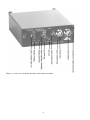
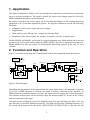
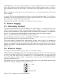
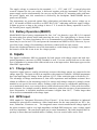
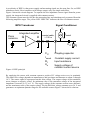
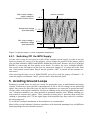
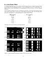
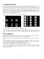
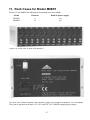
Instruction Manual
Charge
Amplifiers
M68 Series
Manfred Weber
Metra Mess- und Frequenztechnik in Radebeul e.K.
Meissner Str. 58 - D-01445 Radebeul
Phone +49-351-836 2191 Fax +49-351-836 2940
Email: [email protected] Internet: www.MMF.de
The latest version of this document can be downloaded from:
http://www.mmf.de/product_literature.htm
© Manfred Weber
Metra Mess- und Frequenztechnik in Radebeul e.K.
Aug. 10
#162
Contents
1.Application................................................................................................................................5
2.Function and Operation.............................................................................................................5
3.Power Supply............................................................................................................................6
3.1.Grounding Concept............................................................................................................6
3.2.External Supply .................................................................................................................6
3.3.Battery Operation (M68D1)...............................................................................................7
4.Inputs........................................................................................................................................7
4.1.Charge Input ......................................................................................................................7
4.2.IEPE Input .........................................................................................................................7
4.2.1.Switching Off the IEPE Supply .................................................................................9
5.Avoiding Ground Loops............................................................................................................9
6.Amplifier ...............................................................................................................................10
7.Level Indicators.......................................................................................................................10
8.Low Pass Filter .......................................................................................................................11
9.High Pass Filter.......................................................................................................................12
10.Integrators.............................................................................................................................12
11.Rack Cases for Model M68R1..............................................................................................15
12.Technical Data......................................................................................................................16
Appendix:
Limited Warranty
Declaration of Conformity
Figure 1: Front view of Model M68D1 with control elements
4
1. Application
The Signal Conditioners of M68 series are intended for connection of piezoelectric acceleration,
force or pressure transducers. The input is suitable for sensors with charge output as well as for
IEPE compatible transducers or microphones.
By means of the M68 the sensor signal can be best possibly adapted to the existing measuring
equipment or PC-based data acquisition systems. The Signal Conditioners provide the following
functions:
• Adaptation of the sensor signal and sensor supply
•
Amplification
•
High- and low-pass filtering (for example anti-aliasing filter)
•
Integration of the sensor signal, for instance, to measure velocity or displacement.
Models M68D1 and M68D3 are housed in a rugged aluminum case. Both models can be used in
laboratory as well as under field conditions. Model M68D1 may also be operated from batteries.
Model M68R1 has been developed for multichannel measuring systems. It fits into 19”-rack
systems.
2. Function and Operation
Figure 2 shows the block diagram of Model M68 with its most important functional groups.
IEPE
supply
IEPE
J1 (ICPon/off)
Gain
Frequency
0.1Hz
a
Gain
3Hz
Input
U
Q/10
Q
Q1
U
Q/10
Q
V1
High
pass
Low pass
v
d
V2
1. Int.
2. Int.
Q2
+
Output
V=1
Comparator
>5%
Comparator
Overload
Figure 2: Block diagram
Depending on the position of the input switch, the input signal passes the impedance converter
Q1 or Q2. If IEPE operation is selected, the signal is directly connected to the amplifier. At
IEPE operation a constant current is fed into the input socket to supply the sensor electronics.
The constant current source can be switched off by the internal jumper J1, in case an AC voltage
shall be connected to the input.
The input circuit is followed by the first amplifier stage, low pass and high pass filters. The low
pass filter has 6 selectable limiting frequencies. The high pass filter has a limiting frequency of 3
Hz, which can be bypassed by the switch “HIGH PASS / INTEGRATOR”. In this case the full
5
bandwidth down to 0.1 Hz comes into effect. The filters are followed by the second amplifier
stage. The divided gain before and after filtering provides sufficient dynamic range, even for signal components outside the filter range. At the same time a high signal-to-noise ratio is achie ved.
Before reaching the output driver the signal may pass one or two integrating stages. The output
is DC coupled.
A control LED for the output modulation indicates an output signal higher than 5 % of full-scale
modulation. An overload LED shows if the output signal exceeds 90 % of full-scale modulation.
It also indicates overload before the filter stages.
Models M68D1, M68D3, and M68R1 have identical electronic circuits.
3. Power Supply
3.1. Grounding Concept
The inputs and outputs of the signal conditioners are single ended, i.e. asymmetrical. In case an
additional signal ground connection is required, ground is available via a separate connector at
the rear of the instruments. For the Models M68D1 and M68D3 this connector is a 4 mm banana jack. The signal ground of Model M68R1 can be found at the 4-pole frame connector.
The case of the instruments is internally connected to ground.
If model M68R1 is used with the rack cases M68B6 and M68B12 a connection is made between
signal ground and protective earth potential via the case.
The power supply is separated from signal ground. In some cases it may be of advantage to
connect the minus pole of the power supply to signal ground, to avoid ground loops. For this
purpose you can plug in the 4 mm jumper (delivered with the instruments) at the rear of Models
M68D1 and M68D3. At Model M68R1 the terminals of the power supply socket can be connec ted by a wire.
3.2. External Supply
The Signal Conditioners M68 are powered by an external DC voltage
Models M68D1 and M68D3 come with a mains plug adapter for 115/230 VAC. The power supply socket according to DIN 45323 is located at the rear of the instruments. Any other voltage of
5 V to 15 V DC and about 300 mA (for M68D1) or 1 A (for M68D3) may be connected to this
socket. The positive supply terminal is connected to center pin (tip). The POWER ON/OFF
switch is located at the rear.
The M68R1 also has its power supply connector at the rear. It is a 4-pole frame connector type
WAGO 232. The pin designation is shown in Figure 3.
+ 5 .. 15 V
0V
0V
Signal ground
Figure 3: Power supply socket of Model M68R1
6
The supply voltage is connected to the terminals “+ 5 .. 15 V“ and “0 V”. A special plug with
screwed contacts for the rear socket is delivered together with the instrument. This way the
power supply can be wired manually. In case you use the offered 19”-mounting racks with internal power supply unit, this connection is realized by the backplane. Model M68R1 has no
power on/off switch.
The instruments are protected against false polarization and short-time excess voltage up to
60 V. All models of M68 series have an LED “BAT O.K.” indicating sufficient supply voltage.
It lights up green, as long as the voltage is above 5 V. It works for battery operation as well as
for external power supply (M68D1).
3.3. Battery Operation (M68D1)
Model M68D1 has a battery compartment for four “AA” size batteries (type LR 6). It is opened
by unscrewing four plastic knobs and removing the cover. The right polarity is shown on the
battery holder. To ensure long battery life it is recommended to use alkaline batteries. Accumulators may be used as well. You can operate the instrument on NiMH or NiCd. However, by rea son of the lower voltage of accumulators, the battery control will not work exactly.
Please take discharged batteries out of the instrument to avoid damage by leakage. Also, remove
the batteries if the unit is not in use for a longer period.
4. Inputs
The Signal Conditioners M68 are designed for both sensors with charge output and with inte grated impedance converters to IEPE standard as well. You can switch from one to the other
type of transducer by means of the slide switch next to the input socket. Both input types use the
same BNC input socket.
4.1. Charge Input
Capacitive signal sources, usually piezoelectric sensors with charge output, are connected to the
charge input (Q). The input is fed to an amplifier with capacitive feedback. All M68 instruments
have two input stages for charge. In the position “Q/10” of the switch the gain is divided by 10.
The advantage of charge measurement is, that cable capacitance and insulation resistance have
almost no influence to the measuring result. For sensors with charge output it is strongly recommended to use special low-noise cables. Ordinary cable will cause a considerable measuring error at mechanical stress, as a result of the so-called triboelectrical effect. Cables with low insula tion resistance, for example caused by humid connectors, reduce the accuracy of measurement at
lower frequencies. A desirable insulation resistance is higher than 10 GΩ. Cables longer than
10 m are not recommended at the charge input.
4.2. IEPE Input
IEPE stands for "Integrated Electronics Piezo Electric". It has been established as industrial
standard for piezoelectric transducers. Other brand names for the same principle are ICP ®, Isotron®, Deltatron®, Piezotron® etc. The integrated sensor circuit transforms the charge signal of
the piezo-ceramics, with its very high impedance and high EMI sensitivity, into a voltage signal
with low impedance. The converted signal can be easier transmitted. The cable length at this input may be more than one hundred meters. Ordinary low cost coaxial cable can be used.
7
A peculiarity of IEPE is, that power supply and measuring signal use the same line. So, an IEPE
transducer needs, like a transducer with charge output, only one single-ended line.
Figure 4 shows the circuit diagram. To separate the low impedance sensor signal from the power
supply, the integrated circuit is supplied with constant current.
This constant current must be fed into the measuring line and simultaneously separated from the
following amplifier stages. The yellow LED “IEPE ON” indicates the flow of constant current.
IEPE Transducer
Signal Conditioner
Us
Integrated amplifier
Piezo
ceramics
Q
U
coaxial cable,
> 100 m
I const
CC
CC
I const
Coupling capacitor
RI
U
Input resistance
s
RI
Constant supply current
Supply voltage of
constant current source
Figure 4: IEPE principle
By supplying the sensor with constant current a positive DC voltage arises over its terminals.
This static bias voltage depends on manufacturer and specimen and amounts to about 5 through
14 V. The sensor signal is superposed on this bias voltage. The output voltage of the transducer
never changes to negative values. Its minimum value is the saturation voltage of the integrated
impedance converter (0.5 V to 1 V). The supply voltage of the constant current source determines the maximum value of the output voltage. For the M68 this voltage amounts up to 24 V and
guarantees an optimum dynamic range for all available sensors.Figure 5 shows these relations.
8
Max. output voltage =
supply voltage of
constant current source
positive overload
24 V
Sensor bias voltage 5 .. 14 V
(see data sheet)
Min. output voltage =
saturation voltage
(see data sheet)
0.5..1 V
0V
negative overload
Figure 5: Dynamic range of IEPE compatible transducers
4.2.1. Switching Off the IEPE Supply
In some cases it may be necessary to switch off the constant current supply, in order to use the
input for normal AC sources. For this purpose, please change the position of the jumper, which
you will find at Models M68D1 and M68R1 behind the front panel. Remove the cover of Model
M68D1 by unscrewing the four plastic screw heads. To remove the cover of Model M68R1,
four screws at the side and two at the back are unscrewed. Jumper J1 is located left at the front
side of the printed circuit board. Plug it into the position “OFF” to switch off the constant cur rent source.
After removing the front cover of Model M68D3 you will see only the jumper of channel 1. To
reach the jumpers of channels 2 and 3, please remove front and rear panel.
5. Avoiding Ground Loops
Earthing or ground loops are often the reason for measuring errors in multichannel measuring
systems. In most cases you will find a superimposed 50 Hz or 100 Hz voltage on the measuring
signal. One reason for this effect may be, that the transducers are connected to ground not only
via their cable at the signal conditioner, but also in addition at the measuring point through their
case. Vibration transducers are often mounted at grounded machine parts. Within earthing systems transient currents may appear. These transient currents cause a potential drop across the
earthing or grounding wires. Via the signal input of the amplifier they may result in a considerable measuring error.
To avoid this, insulated attachment of the transducers is recommended.
Metra offers several industrial vibration transducers with insulated mounting base and different
insulating flanges for non-insulated sensors.
9
A star-shaped grounding network is the ideal solution to avoid ground loops. Star-shaped means
that all grounding wires of the sensors and the amplifier outputs are tied to ground at the signal
conditioners, without any transverse connections. In many cases this is more difficult to realize
for the outputs than for the inputs, because the following measuring equipment may have singleended, inputs. If you have the choice to use differential inputs, which can be found on many
data acquisition boards, you should preferably use them.
6. Amplifier
The instruments of M68 Series have the following measuring ranges:
Charge mode:
0.1 / 1 / 10 / 100 / 1000 mV/pC
IEPE mode:
1 / 10 / 100 / 1000 times
The gain selection switch ”GAIN” has four positions. In position “Q/10” of the input selection
slide switch the measuring range of all charge ranges is divided by 10. This may be advanta geous for measurement with high sensitivity transducers or for shock measurement.
After connecting a sensor and occasionally after changing the measuring range, the amplifier
needs a certain settling time because of a short term overload. Therefore it may take up to 30 s,
until the output voltage is free of DC components.
The amplifier output is buffered and DC-coupled. Therefore, possible offset currents fed into the
amplifier output by the following equipment (for instance a PC data acquisition board), do not
cause a DC offset.
7. Level Indicators
LEDs indicate minimum modulation and overload condition.
The LED “>5%” lights up at an output voltage higher than 0.7 V. The LED “OVL” lights up if
the output voltage exceeds 9 V.
The optimum gain range is selected, if the LED “>5%” lights up and the LED “OVL” remains
dark. If both LEDs remain dark, the gain should be increased. If both LEDs light up the gain
should be reduced.
The overload detector monitors both the amplifier output and the filter input (see Figure 2). By
that means overload condition will also be indicated when high signal components beyond the
filter pass band occur.
An overload detector at the integrator input is not provided. In some cases high level components at higher frequencies may overload the amplifier stage before the integrator while at the
integrator output no overload condition can be detected. To avoid this, make sure to check the
signal level in the switch position “ACC” (integrator off) before switching on the integrators.
When the LED indicates overload you can use the low pass filter to attenuate high frequencies.
10
8. Low Pass Filter
To eliminate disturbing noise or to comply with the Shannon theorem: “Signal frequency should
be less than half of the sampling frequency”, it can be advantageous, to use a low pass filter. For
higher accuracy in the time domain it is recommended to set the low pass at 1/10 the sampling
frequency.
The instruments of M68 series have 6 internal low pass filters. The scale at the positions of the
filter switch “LOW PASS” is shows the 3 dB limiting frequencies in kHz. The following table
shows the 3 dB and the 10 % limiting frequencies of the low pass filters:
3 dB Frequency
100 Hz
300 Hz
10 % Frequency
70 Hz
200 Hz
1 kHz
10 kHz
700 Hz
7 kHz
20 kHz
50 kHz
14 kHz
35 kHz
The slope of the low pass filters is 40 dB per decade.
0 dB
50 kHz
180°
90°
1 kHz
10 kHz
20 kHz
0
-20 dB
-90°
-40 dB
0,1
1
kHz
10
-180°
0,1
100
0 dB
50 kHz
20 kHz
10 kHz
1 kHz
1
kHz
10
100
180°
90°
100 Hz
300 Hz
0
-20 dB
-90°
300 Hz
100 Hz
-40 dB
10
100
Hz
1000
10000
-180°
10
100
Figure 6: Typical frequency and phase response of the low pass filters
11
Hz
1000
10000
9. High Pass Filter
The M68 signal conditioners have a high pass filter with a lower limiting frequency of 3 Hz (3 dB). By means of this filter low frequency noise can be removed. Low frequency noise may
occur, for example, by the influence of temperature transients to piezoelectric compression type
accelerometers. The slope of the 3 Hz high pass filter is 40 dB / frequency decade. The 3 Hz
high-pass filter is switched on by turning the “INTEGRATOR HIGH PASS” switch into positi on “ACC 3 Hz”. If the high pass filter is switched off (switch position “0.1 Hz ACC”), the lower
limiting frequency of the amplifier is 0.1 Hz.
With the integrators the high pass filter is always switched on.
180°
0 dB
90°
0
-20 dB
-90°
-40 dB
0,1
-180°
1
Hz
10
100
0,1
1
Hz
10
100
Figure 7: Frequency and phase response of the high pass filter
As the filters are located between the amplifier stages (see Figure 2) the instrument does not become overloaded, even if the measured signal has higher spectral components outside the filter
range.
10. Integrators
The M68 can integrate the measuring signal one or two times. Integration can be useful for vi bration measurement by means of accelerometers on rotating machinery.
Single integration of vibration acceleration results in velocity, double integration in displacement.
The „INTEGRATOR HIGH PASS“ switch activates the integrators. In position “ACC“ (acceleration) the measuring signal passes without integration. At the position “VEL” (velocity) the signal is integrated once, in position “DISP” (displacement) twice.
With switched on integrators the 3 Hz high pass filter is always activated.
The following calculations show how the M68 output uout corresponds to the three vibration
quantities. The selected gain range of the M68 is G and the accelerometer sensitivity (see transducer data sheet) is Bua.
12
Vibration acceleration a (without integration):
a=
uout
G⋅Bua
(a in m/s²; uout in mV; G in mV/mV; Bua in mV/ms-2)
Vibration velocity v (single integration):
v=
uout
⋅10
G⋅Bua
(v in mm/s; uout in mV; G in mV/mV; Bua in mV/ms-2)
Vibration displacement d (double integration):
d=
u out
⋅100
G⋅Bua
(d in µm; uout in mV; G in mV/mV; Bua in mV/ms-2)
The equations above apply for IEPE compatible accelerometers. For accelerometers with charge output,
G is replaced by the selected charge amplifier range in pC/g and B ua is replaced by the transducer’s charge sensitivity Bqa.
Example:
Vibration velocity is measured using an accelerometer with a sensitivity of B qa= 5 pC/ms-2. The M68 is
operated in the range G=100 mV/pC. Its output voltage is 300 mVrms. What is the corresponding vibration velocity?
Solution:
v=
300
⋅10=6 mm/ s RMS
100⋅5
Often a direct connection between the output voltage of the M68 and the measured physical
quantity (for example “1 mV corresponds to 1 mm/s”) is desired.
This can be achieved by adjusting the connected measuring equipment or by typing in a correction factor
in a PC based data acquisition system. In the example given above this correction factor would be 0.02.
At higher frequencies the output voltage will have only small amplitudes after integration. The dynamic
range and the signal-to-noise ratio therefore become lower in the kHz-range (Figure 8).
13
dB
20
Max.
modulation
%
Modulation limits
Sin
gle
0
100
int
eg
rat
i
l
ub
Do
on
e
10
n
io
at
gr
te
in
-20
-40
1
0.1
1
10
Hz
100
1000
Figure 8: Frequency response of the integrators
180°
90°
0
-90°
-180°
0.1
1
10
100
1000
Figure 9: Pase response of the integrators
In some cases signal components with high frequency and magnitude may overload the amplifier although no overload can be detected at the M68 output. The overload LED remains dark.
This can occur due to the attenuation of higher frequencies by the integrator (compare Figure 8).
To avoid possible overload, make sure to check the signal level in the switch position “ACC”
(integrator off) before using the integrator. If an overload condition should be indicated, reduce
high frequency components by an appropriate low pass frequency.
14
11. Rack Cases for Model M68R1
For the 19” unit M68R1 the following rack mounting cases are available:
Model
M68B6
M68B12
Channels
6
12
Built-in power supply
yes
yes
Figure 10: Front view of rack case M68B12
Figure 11: Rear view of rack case Model M68B6
The rack cases Models M68B6 and M68B12 supply the plugged-in modules via a backplane.
They can be operated with both 115 VAC and 230 VAC without changing any settings.
15
The fuse holder of the rack cases M68B6 and M68B12 with mains power supply is located inside the mains socket at the rear. It can be pulled out using a screw driver. The fuse facing to the
back of the drawer is a spare fuse. The rear one is the mains fuse.
Important:
Unplug the device from the mains voltage before replacing the fuse.
Make sure that the fuse to be replaced has the rating T 800 mA.
12. Technical Data
Measuring inputs
Charge and IEPE compatible, RI > 5 MΩ
BNC socket, single-ended
IEPE sensor supply
3.8 .. 5.6 mA constant current,
compliance voltage 24 V,
switched off by internal jumper,
LED indicator
Gain
0.1 / 1 / 10 / 100 / 1000 mV/pC (charge)
1 / 10 / 100 / 1000 (IEPE)
Accuracy
± 1 % typical, referred to full scale output
± 2 % maximum, referred to full scale output
Low pass filter (-3 dB)
0.1 / 0.3 / 1 / 10 / 20 / 50 kHz, two poles, 40 dB/decade
High pass filter (-3 dB)
3 Hz, two poles, 40 dB/decade, can be switched off
Frequency range
of integrators
Single integration:
Double integration:
Output
± 10 VPEAK, DC coupled, DC offset < 10 mV,
ROUT = 100 Ω, BNC socket, single-ended
Cross-talk attenuation
> 60 dB (M68D3 at 1 kHz / V=1000)
Output noise with
charge input
< 15 mVrms (0.1 Hz .. 50 kHz bandwidth) and
< 8 mVrms (3 Hz .. 20 kHz bandwidth)
Output noise with
IEPE input
< 10 mVrms (0.1 Hz .. 50 kHz bandwidth) and
< 6 mVrms (3 Hz .. 20 kHz bandwidth)
LED indicators
Minimum modulation: > 0.7 VPEAK
Overload: > 90 % of full-scale output
Battery: supply voltage > 5 V
16
3 .. 1000 Hz
3 .. 100 Hz
External supply
5 .. 15 VDC
< 300 mA (M68D1, M68R1)
< 1 A (M68D3)
connector to DIN 45323 (M68D1 / M68D3)
4 pin frame connector (M68R1)
Battery supply
(only M68D1)
4 x “AA” size (LR6)
> 10 h lifetime with alkaline cells
Wide range input 85 .. 264 VAC
Mains supply
(only M68B6 / M68B12) Socket for IEC 320 mains cord
Grounding required
Power consumption: < 40 W
Fuse: 800 mA (slow) in mains socket
Mains plug adapter
(only M68D1 / M68D3)
Wide range input 100 .. 240 VAC, 50 / 60 Hz
with two pole Euro plug
Output: 12 VDC / 0.5 A (M68D1) / 1 A (M68D3)
Warm-up time
15 minutes
Operating temperature
-10 .. 50 °C, 95 % rel. humidity without condensation
Dimensions
(width x height x
depth)
105 x 40 x 150 mm³ (M68D1)
105 x 90 x 140 mm³ (M68D3)
7 width units x 3 height units x 190 mm (M68R1)
17
Limited Warranty
Metra warrants for a period of
24 months
that its products will be free from defects in material or workmanship
and shall conform to the specifications current at the time of shipment.
The warranty period starts with the date of invoice.
The customer must provide the dated bill of sale as evidence.
The warranty period ends after 24 months.
Repairs do not extend the warranty period.
This limited warranty covers only defects which arise as a result
of normal use according to the instruction manual.
Metra’s responsibility under this warranty does not apply to any
improper or inadequate maintenance or modification
and operation outside the product’s specifications.
Shipment to Metra will be paid by the customer.
The repaired or replaced product will be sent back at Metra’s expense.
18
Declaration of Conformity
Products: Charge Amplifiers
Models: M68D1, M68D3, M68R1, M68B6, M68B12
It is hereby certified that
the above mentioned products
comply with the demands
pursuant to the following standards:
•
EN 50081-1
•
EN 50082-1
•
EN 61000-3
•
EN 60950
Responsible for this declaration is the producer
Metra Mess- und Frequenztechnik
Meißner Str. 58
D-01445 Radebeul
Declared by
Manfred Weber
Radebeul, 29th of May, 2001
19