1
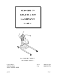
OPERATOR/SERVICE MANUAL MODEL: 75D WALK BEHIND ROLLER Stone Construction Equipment, Inc. P.O. Box 150, Honeoye, New York 14471 Phone: (800) 888-9926 Fax: 716-229-2363 A 100% employee-owned American manufacturer © 1996 Stone Construction Equipment, Inc. Printed in U.S.A. REVISION: A 1/96 P/N 56233 Contents 75-D ROLLER LIMITED WARRANTY .................................................................................................................................. SPECIFICATIONS ...................................................................................................................................... 1 SERVICE CHECK LIST .............................................................................................................................. 2 SAFETY PRECAUTIONS ........................................................................................................................ 3,4 OPERATIONAL SAFFETY PRECAUTIONS ................................................................................................ 5 Always ........................................................................................................................................................ 5 Never .......................................................................................................................................................... 5 Before Using the Machine ........................................................................................................................... 6 Conditon of Decals ...................................................................................................................................... 6 Gradient Working ......................................................................................................................................... 6 Maintenance Safety .................................................................................................................................... 6 Hazardous Materials ................................................................................................................................... 7 PARTS DIAGRAM ............................................................................................................................... 18-49 Left Hand Side Assembly .................................................................................................................... 18,19 Roll Assembly ...................................................................................................................................... 20,21 Drum Brake Assembly ......................................................................................................................... 22,23 Transmission Drive Assembly .............................................................................................................. 24,25 Vibrator Drive Assembly ...................................................................................................................... 26,27 Chassis Crossmember, Engine Platform and Scraper Bars .................................................................. 28,29 Hydraulic Pump and Vibrator Clutch Drive ............................................................................................ 30,31 Engine and Accessories - Hatz Only .................................................................................................... 32,33 Hydraulic System - Valve, Motor and Pump ......................................................................................... 34,35 Hydraulic System - Tank and Filters ..................................................................................................... 36,37 Water Tanks, Drive Guard and Spray Equipment .................................................................................. 38,39 Steering Arm Controls .......................................................................................................................... 40,41 Steering Arm ........................................................................................................................................ 42,43 Decal Identification .............................................................................................................................. 44,45 LIMITED WARRANTY The Manufacturer warrants that products manufactured shall be free from defects in material and workmanship that develop under normal use for a period of 90 days for concrete vibrators and electric pumps, one year for Rhino®, Bulldog®, Wolfpac Rollers, trowels, Stompers®, saws, plates, engine powered pumps, and 6 months for all other products from the date of shipment. The foregoing shall be the exclusive remedy of the buyer and the exclusive liability of the Manufacturer. Our warranty excludes normal replaceable wear items, i.e. gaskets, wear plates, seals, O-rings, V-belts, drive chains, clutches, etc. Any equipment, part or product which is furnished by the Manufacturer but manufactured by another, bears only the warranty given by such other manufacturer. (The Manufacturer extends the warranty period to "Lifetime" for the drum bearings and seals for the mortar mixers, and agrees to furnish, free of charge, the bearings and seals only upon receipt of the defective parts and a Warranty Evaluation Form. The eccentric bearings are warrantied for two years on the plate compactors and five years on the Bulldog line, the trowel gearboxes are warrantied for two years, plus a Warranty Evaluation Form must accompany the defective parts.) Warranty is voided by product abuse, alterations, and use of equipment in applications for which it was not intended, use of non-manufacturer parts, or failure to follow documented service instructions. The foregoing warranty is exclusive of all other warranties whether written or oral, expressed or implied. No warranty of merchantability or fitness for a particular purpose shall apply. The agents, dealer and employees of Manufacturer are not authorized to make modification to this warranty, or additional warranties binding on Manufacturer. Therefore, additional statements, whether oral or written, do not constitute warranty and should not be relied upon. The Manufacturer's sole responsibility for any breach of the foregoing provision of this contract, with respect to any product or part not conforming to the Warranty or the description herein contained, is at its option (a) to repair, replace or refund such product or parts upon the prepaid return thereof to location designated specifically by the Manufacturer. Product returns not shipped prepaid or on an economical transportation basis will be refused (b) as an alternative to the foregoing modes of settlement - the Manufacturer's dealer to repair defective units with reimbursement for expenses, except labor, and be reviewed with the Manufacturer prior to repair. A Warranty Evaluation Form must accompany all warranty claims. Except as set forth hereinabove and without limitation of the above, there are no warranties or other affirmations which extends beyond the description of the products and the fact hereof, or as to operational efficiency, product reliability or maintainability or compatibility with products furnished by others. In no event whether as a result of breach of contract or warranty or alleged negligence, shall the Manufacturer be liable for special or consequential damages including but not limited to: Loss of profits or revenues, loss of use of the product or any associated product, cost of capital, cost of substitute products, facilities or services or claims of customers. No claim will be allowed for products lost or damaged in transit. Such claims should be filed with the carrier within fifteen days. Effective December 1, 1995. MODEL NUMBER ___________________ Serial No.__________________________ Stone Construction Equipment, Inc. Corporate Offices/Northern Mfg. Plant 32 East Main Street, P.O. Box 150 Honeoye, NY 14471-0150 Phone: 1-800-888-9926 Phone: (716) 229-5141 FAX: (716) 229-2363 75H 75H Drum Type Dual Dual Dimensions Operating Wt. 2120 lbs. 960 kg Shipping Wt. 2205 lbs 1000 kg 109"x35"x46" 2780 x 892 x 1170 mm Operating Length 109" 2780 mm Drum Width 30" 760 mm Drum Dia. 19" 485 mm Curb Clearance 9.5" 242 mm Wall Clearance 1.0 / 4.2" 26 / 106 mm Hydrostatic Hydrostatic 11.3 hp Hatz 8.4 kw Hatz 2500 rpm 2500 rpm 2.2 gallons 8.25 Liters 3.6 gallons 13.5 Liters non-corrosive dual spray bars non-corrosive dual spray 12 / 10 gallons 45 / 38 Liters Performance Max. Travel Speed 0-2 mph 0-3.2 km/h Eccentric Force 5400 lbs. 24 kn Frequency 3900 vpm 65 hz Macimum Lift .02" .5 mm Gradability w/vibration w/o vibration 33% 50% 33% 50% Safety Features Deadman's Handle Deadman's Handle Standards Freewheel System Parking Brake Adjustable Scrapers Freewheel System Parking Brake Adjustable Scrapers MODEL LXWXH Operating System Drive System Engine Options Engine RPM's Fuel Capacity Hydraulic Capacity Water System Water Tank Capacity REVISION: PAGE 1 SERVICE CHECK LIST USEFUL INFORMATION Model/Capacity ________________________ Service VIN ________________________ 1 Purchase Date ________________________ 2 Engine Make/No. ________________________ 3 ________________________ 4 ________________________ 5 Oil Specifications & Quantity 6 Engine ________________________ 7 Hydraulic ________________________ 8 ________________________ 9 Date Safety It is recommended the driver is adequately trained in the safe operation of this machine, has been authorized to operate it and has sufficient knowledge of the machine to assure himself that it is in full working order before use. Stone Construction Equipment, Inc. 32 East Main Street Honeoye, NY 14471 USA PAGE 2 For Service/Spare Parts: 1-800-888-9926 1-716-229-5141 Fax: 1-716-229-2363 REVISION: HEALTH & SAFETY SAFETY These machines are designed to carry out the function of compacting material of the non-cohesive, bituminous and granular varieties. If used correctly they will provide an effective and safe means of compaction and meet the appropriate performance standards. It is essential that the drive/operator of the machine is adequately trained in its safe operation, be authorized to drive it, and have sufficient knowledge of the machine to ensure that it is in full working order, before being pout to use. SAFETY PRECAUTIONS Before using this equipment, study this entire manual to become familiar with its operation. Do not allow untrained or unauthorized personnel, especially children, to operate this equipment. Use only factory authorized parts for service. When warning decals are destroyed or missing, contact the Manufacturer immediately at 1-800-888-9926 for replacement. For the safety of yourself and others, it is imperative that the following rules are observed. Failure to do so may result in serious injury or death. This notation appears before warnings in the text. It means that the step which follows must be carried out to avoid the possibility of personal injury or death. These warnings are intended to help the technician avoid any potential hazards encountered in the normal service procedures. We strongly recommend that the reader takes advantage of the information provided to prevent personal injury or injury to others. USE COMMON SENSE WHEN HANDLING FUELS Transport and handle fuel only when contained in approved safety container. Do not smoke when refueling or during any other fuel handling operation. Do not refuel while the engine is running or while it is still hot. If fuel is spilled during refueling, wipe it off from the engine immediately and discard the rag in a safe place. Do not operate the equipment if fuel or oil leaks exist - repair immediately. Never operate this equipment in an explosive atmosphere. Ear protection required when operating this equipment. REVISION: PAGE 3 Avoid contact with hot exhaust systems and engines. Allow engine to cool before performing any repairs. Never operate unit in a poorly ventilated or enclosed area. Avoid prolonged breathing of exhaust gases. Keep feet clear of all drums. Keep work area free of bystanders For foot protection, wear steel toe shoes or toe pads. Caution: Escaping hydraulic fluid under pressure can have sufficient force to penetrate the skin, causing serious personal injury. Hydraulic fluid escaping under pressure from a very small hole can be almost invisible. Use a piece of cardboard or wood to search for possible leaks. Never use your hands to detect pressure leaks. Hydraulic tank temperature can reach 180 degrees F maximum. PAGE 4 REVISION: Operational Safety Precautions When using this machine the following list of basic Do ‘ s and Don'ts should be applied. This list is not necessarily a complete list, but applying these rules will greatly reduce the possibility of an accident occurring. Always • Carry out a daily pre-check of the machine, see Care and Maintenance section. • Look around the machine before starting the engine - children could be out of sight. • Before starting the engine, ensure the transmission control lever is in the NEUTRAL position. • Examine working area for possible dangers such as trenches, confined areas and people working. • Clear away obvious hazards and always operate with caution. • Ensure you have a clear view when driving. • Exercise great care when working on gradients - especially when crossing. • Refuel the roller when the engine is stopped. • Winch or lift the roller from any situation where it cannot extricate itself. • Wear appropriate protective clothing, headgear and noise protectors, where necessary. Never • Attempt to ‘jump’ obstacles such as curbs and manholes. • Drive at speed over rough ground - drive slowly. • Leave the roller unattended with the engine running. • Carry out maintenance unless the engine is stopped and the drums are blocked. • Tamper with any of the safety devices on the machine. • Tighten or disconnect any hose while the engine is running. REVISION: PAGE 5 Safe Operation Decals The machine has a number of special decals fitted which draw the users attention to various points of operation or safety. Before Using the Machine Read all the decals attached to the machine and fully understand their meaning. If you don't understand their meaning contact your supervisor for clarification. Condition of Decals Ensure the decals are always clean and readable, replace when necessary. Spare decals are obtainable from the Manufacturers Customer Service Department. Gradient Working In the General Specification section of this handbook, details are given of the recommended gradient capability of the machine. The gradients quoted give a general guide as to performance, but conditions existing on site in terms of ground conditions and vehicle speed will have an effect on machine stability, an allowance for which must be made by the driver. Maintenance Safety When carrying out routine or scheduled servicing insure: The machine cannot be inadvertently started All fluids are handled with care and protective gloves and eye protectors are used where necessary. Always service the engine as detailed in the Engine Manufacturers Handbook. PAGE 6 REVISION: HAZARDOUS MATERIALS 'VITON' Seals and 'O' Rings WARNING Seals and 'O' rings are made from 'Viton' - Fluorocarbon Elastomer - which is combustible and can be dangerous if handled incorrectly. Under extreme conditions, the burning of 'Viton' material may produce Hydrofluoric Acid and Hydrogen Fluoride. If 'Viton' seals and O'rings burn, precautions must be taken to prevent the 'Viton' from coming into contact with the SKIN. Handle ALL burnt seals and 'O' rings only when wearing Neoprene gloves. Any part of the gloves which have been in contact with 'Viton' should be washed well with Limewater - Calcium Hydroxide solution immediately after use. As it is difficult to identify which seals are made from 'Viton' and which are not, we recommend the above instructions be adhered to when handling ANY burnt seals or 'O' rings. ASBESTOS WARNING It is possible that some proprietary parts used on this machine use gaskets which have an asbestos content. This asbestos will be of the 'white' (chrysotile) type which is a lower risk material. However, risk does occur if the joint is damaged, therefore when undertaking engine maintenance ensure: REVISION: • Protective gloves are used. • The joint is wet to help contain loose fibers. • Gasket is not ground off - use a scraper. • Material is disposed of safely. PAGE 7 ROLLER GENERAL SPECIFICATION Engine Options Hatz Diesel ES786 8.4kW (11.2 hp) at 2500 rpm (DIN 6270"B”) Weights Total Operating Weight per meter of drum width 960 kg / 2117 lbs 631 kg / 1391 lbs Vibrator Type Total Centrifugal Force Frequency Random Circular Path 2400 kg / 5292 lbs 65Hz / 3900 rpm Travel Speed Infinitely Variable 0 3.2 km/h (2 mph) Gradient Performance Without Vibration With Vibration 50% 33% Water Tank Capacity Front Rear 45 liters / 12 gal 38 liters / 10 gal Hydraulic Tank Capacity 13.5 liters / 3.5 gal Fuel Tank Capacity 8.25 liters / 2 gal 46 in 6 in 9.76 in 4.2 in PAGE 8 30 in 1.02 in REVISION: Working Principle and Main Features Introduction The 75D roller is powered by a single or twin cylinder engine running at a constant 2500 rpm. Forward and reverse drive to the roller drums is by means of a hydrostatic transmission. A hydraulic pump, belt driven at constant speed from the engine, supplies oil to a hydraulic motor driving each drum through spur reduction gears. Rubber mountings at each end of the drums isolate the transmission and the operator from the effects of vibration. An eccentric shaft mounted on grease packed ball bearings, is contained within each drum to generate vibration. Drive to each shaft is at constant speed from the engine via a drive shaft, flexible couplings, dry plate clutch and re-tensioned 'Vee' belt running on machined pulleys. Each vibrator shaft, rotating at 3900 rpm to give a frequency of 65 cycles per second, develops a centrifugal force of 1200 kg (2646 lbs). Depending on ground conditions being rolled, this results in each drum striking the surface with a force up to 8.128 kg. Each roller drum is of heavy duty steel construction with seam welded plates to prevent ingress of water. A removable cast aluminum side shield protects and provides access to the drive chain, clutch and vibrator drive belt. Two water tanks, front 45 liters (12 gals) and rear 38 liters (10 gals), are supplied with brass water taps, noncorrosive spray bars and large diameter filling caps for easy cleaning. Front and rear adjustable scraper bars are provided and a parking brake is fitted in the transmission as an added safety precaution. Additionally, when rolling in a confined space, the speed can be regulated to give the degree of control necessary for safety under these conditions. Importance of the Deadmans Safety Lever The vibrating roller will not move forward or in reverse until the deadmans safety lever is pressed home and held by the operator. The action of pressing the lever opens the hydraulic circuits and when the forward/reverse speed lever is engaged enables the roller to move off in either direction and at the required speed. Immediately after, the operator releases the deadmans safety handle the hydraulic circuits are automatically closed and instantly stop the roller--either on the level or on an incline and regardless of the position of the forward/reverse speed lever. The importance of this built-in deadmans safety measure will be instantly recognized and understood by all existing owners, hirers, operators and drivers of vibrating rollers. REVISION: PAGE 9 Operating Controls Direction Lever The direction lever selects forward, reverse or neutral. Speed in either direction is increased as the lever moves away from neutral and is decreased as it moves back. For a smooth, progressive acceleration or deceleration always move the lever gently and slowly. The lever is spring loaded to positively locate in a notched control plate so that neutral position is easily found and also to stop the lever creeping. Vibrator Lever The vibratory lever is of the spring loaded 'over center' type and controls the clutch which starts and stops the vibrator. Move the lever forward to start the vibrator and backward to stop it. Never operate the vibrator when the roller is standing on a hard surface. Deadmans Safety Lever The deadmans safety lever is a quick acting device designed to protect the operator and anyone nearby in the event of involuntary release of the steering controls. All the time the lever is held in against the handgrip, the roller can be driven. Immediately the lever is released, the hydraulic motor drive locks and stops the roller instantly. Parking Brake A parking brake is provided in the drum transmission for additional safety when the roller is left unattended. Starting the Engine Before starting the engine make sure the hydraulic and diesel fuel tanks are full, the direction lever is in neutral, the vibrator lever is in the disengaged position and the parking brake is on. Follow the instructions given in the engine manufactures handbook supplied with the roller. If this is not immediately available, or has gone astray, make certain the sump oil is to the top dipstick mark and the air cleaner is in good condition and correctly fitted and proceed as follows: Set the start/stop control to the 'start' position, i.e. lever almost vertical, and set the speed control lever to the full speed position, i.e. lever pulled fully towards starting handle. PAGE 10 REVISION: Operating Controls cont'd Lift and hold the decompressor levers and use the starting handle to crank the engine as fast as possible. Push decompressor to the horizontal and carry on cranking until the engine fires. When the engine runs evenly turn the start/stop control to the 'run' position. Driving the Roller With the engine running release the parking brake and check again the direction lever is in neutral, take a firm hold of the handlebar and squeeze the deadmans safety lever in flush with the handgrip and hold. Slowly move the direction lever in the direction you wish to travel. To increase speed, move the lever gradually towards the full extent of travel until the required speed has been attained. When constantly rolling forwards and backwards, move the direction lever forward into neutral, pause for a moment, then move into reverse, gradually increasing speed as the drive is gently taken up. Apply the same procedure when changing from forward to reverse drive. Gentle movement of the control lever between forward and reverse minimizes any strain on the transmission and prevents skidding on the ground each time the direction of travel is changed. Stopping or Parking the Roller Disengage the vibrator if it has been used and move the direction lever to neutral. Release pressure on the deadmans handle. Move the engine speed control lever to the slow position to allow the engine to tick over. Do not leave the roller unattended with the engine running. If you are going to leave the roller then stop the engine and engage the parking brake. In an emergency, the roller stops immediately by releasing pressure on the deadmans lever. This locks the hydraulic motor drive and stops the roller. Immediately after stopping, disengage the vibrator to avoid indentations in the surface being rolled, and move the direction lever into neutral. To stop the engine turn the stop/start lever to the stop position. When Work is Finished, stop the roller and park as described. If temperatures are likely to fall below freezing point, drain the water tanks and spray bars. Water Tank and Spray Bars Spraying the drums with water during rolling is essential to prevent tarmacadam picking up on the drums surface. REVISION: PAGE 11 For this purposes 45 liter (12 gal) front and 38 liter (10 gal) rear water tanks mounted above each drum discharge water thorugh brass spraybars. A tap in each feed pipe varies the water flow rate as required, or cuts it off where hardcore and similar non-sticky surfaces are being rolled. Bearing Lubrication The vibrator shaft bearins are grease packed on assembly and require no periodic lubrication. When bearings are repacked or replaced, fill the bearing but not the cavities on either side of the bearing with ALVANIA R3 grease. All other bearings are sealed for life. Hydraulic System At all times take great care to prevent diret, grit and similar foreeign mater from entering the hydraulic system. They are its enemies. Always use a clean fluid container and be especially careful when checking the level of fluid in the tank, when topping up, and carrying out the annual drainage, cleaning and refilling operation. Daily Check Level of hydraulic fluid. Correct level is shown on sight glass on the side of the tank. Use Shell 'Tellus 37' or an equivalent. If ambient temperatures are outside -15 degrees Celsius (-5 degrees Fahrenheit) or +40 degrees Celsius (104 degrees Fahrenheit), consult manufacturer for further details. Clean down roller. At end of working day, remembering to drain the water and spray bars when low temperatures are expected. First Week and then Monthly Vibrator Clutch. Check movement on clutch plate. The plate should lift off approximately 2 mm (0.078 in) when disengaged and when in the engaged position the operators lever should be free from the stop by approximately 10 mm (0.393 in). If adjustment is needed this should be done on the cable at the operators end. Monthly Check hydraulic system for leaks and all bolts, nuts etc. for tightness. Check Pump Belt Tightness. Remove belt guard and check belt for tightness. Tension is corrrect when a maximum of 6 mm (236 in) play at center of belt is achieved. If adjustment is necessary slacken the three bolts on the pump mounting bracket and slide bracket on its slotted holes until corerectly adjusted. Tighten bolts and refit belt guard. PAGE 12 REVISION: Annually Hydraulic System Drain the Hydraulic System. Remove the drain plug in the side of the tank. Disconnect return hose from the elbow on tank lid and suction hose from cast filter head. Remove hydraulic tank from roller by undoing 12 mm bolts at each end of the tank. Disconnect and discard filter cartridge from filter head on side of hydraulic tank. Remove the twelve 8 mm bolts securing lid and carefully lift off lid cover. Discard sealing gasket and sealing washers. Unscrew the six screws holding the breather/filler cap assembly to the tank lid. Discard the complete assembly complete with gasket. Thoroughly clean out the interior of the tank, flushing through with clean solvent until the interior is clean. Fit a new filter body and sealing ring to the filter head. Reassemble the tank and lid using a new gasket, renew the sealing washers on the 8 mm bolts. Refit the hydraulic tank to front and rear water tanks using existing 12 mm bolts, replace the 12 mm spring and flat washers. Refit the suction hose to outlet on filter head and the return hose to elbow on the tank lid. Fit a new breather/filler cap assembly to the tank lid using the new gasket and screws supplied with the assembly. Carefully clean and replace the magnetic drain plug using new sealing washer. Fill the hydraulic tank to the correct level on the sight gauge with clean, fresh Shell Tellus 37 hydraulic oil. Before starting the engine, the hydraulic system must be 'bled' to remove trapped air. See Bleeding Hydraulic System procedure in the maintenance section. The engine may now be started and left running for 10 minutes. Check the hydraulic system and tanks for leaks and check oil level. Top up as necessary. REVISION: PAGE 13 Gear Drive Remove the side cover and check there is sufficient lubricant on the drive gears. If necessary, lightly regrease the gears with Rocol Grease Type MG. Diesel Power Unit For routine maintenance oil changes, adjustments etc., refer to the engine manufactures handbook supplied with each roller. Check Daily Engine sump oil level Fuel tank level Tightness of engine mounting bolts. Air Cleaner Maximum engine protection against dust is possible only if the air cleaner is serviced at regular intervals. No hard and fast rules apply to the regularity of servicing because operating conditions vary so much. The following is a guide, but users should ensure a regular service schedule is maintained consistent with the usage and working conditions of the roller. A dust cap helps remove dirt from the air before the air is filtered. Depending on site conditions, the dust cap should be removed and emptied at regular intervals. In Severe Conditions, this May be Necessary Daily When the dust cap is removed, clean the filter element using low pressure compressed air to blow the dust out taking care not to damage the element. The filter should be changed annually or after six cleanings. Bleeding Hydraulic System Remove the top allen screw plug from the pump body. Operate the engine decompressor and crank the engine slowly until a continuous stream of hydraulic oil pours from the hole with no air bubbles. Replace the allen screw plug securely. Top up the hydraulic tank to the correct level on the sight gauge and replace the filler/breather cap securely. Deadmans Safety Lever Check for correct operation. A slack cable means sluggish drive or no drive at all. Adjust by slackening off the locknut at the control arm end of the cable. The retaining block is fixed to a plate with three adjustment holes. If cable stretch is more than range of adjustment obtained by screwing the outer cable out of the retaining block, all adjustment should be re- PAGE 14 REVISION: moved by screwing the outer cable fully home into the retaining block. The block should than be unbolted from the retaining plate and moved to the next hole. Normal adjustment may now be obtained by screwing the outer cable through the remaining block. Adjust the cable for the following conditions: With the deadmans control released, the hydrostatic transmission is fully locked and the roller will not move if the direction control lever is moved into either forward or reverse. With the deadmans control in midway position the roller transmission can freewheel allowing the roller to be pushed forward or backwards. With the deadmans control fully degressed, the transmission transmits full drive when the direction control lever is operated. Forward and Reverse Control Lever This is connected to the pump control lever by a "teleflex" stretchless cable. If the roller creeps in either direction when the control lever is in the neutral notch on the control gate, make the following adjustment. Slacken off one of the locknuts holding the outer cable through the swivel joint, either at the machine of the cable, or at the control arm end of the cable. Adjust the outer cable in or out of the swivel until the creep stops and then retighten the locknut. The lever is held in the desired position by means of a friction washer. Friction washer tension is adjusted by means of a hexagonal nut and may be tightened or slackened. Parking Brake Adjustment Brake shoe wear or cable stretch will affect handbrake efficiency. To adjust the cable: Remove the molded plastic top of the handbrake lever to reveal a hexagonal adjuster which should be turned clockwise to take up any slack. Take care not to over adjust the brake as this may cause a permanent application of the brake, leading to overheating, excessive drag on the engine and damage to the brake shoes. REVISION: PAGE 15 'Vee' Belt Adjustment Remove side cover and inspect belt for signs of a loose cover, cover swell, excessive wear or damage and that the belt is running correctly in the pulley grooves. Adjusting Belt Tension Check tension by measuring deflection of the belt midway between the two vibrator shaft pulleys. When correct this deflection should measure 9.5 mm (.374 in) when a deflecting force of between 2-2.75 kg (4.5 - 6.0 lbs) is applied. This may be adjusted by moving the jockey pulley position. PAGE 16 REVISION: EXPLODED DIAGRAMS & PARTS LIST Left Hand Side Assembly .................................................................................................................... 18,19 Roll Assembly ...................................................................................................................................... 20,21 Drum Brake Assembly ......................................................................................................................... 22,23 Transmission Drive Assembly .............................................................................................................. 24,25 Vibrator Drive Assembly ...................................................................................................................... 26,27 Chassis Crossmember, Engine Platform and Scraper Bars .................................................................. 28,29 Hydraulic Pump and Vibrator Clutch Drive ............................................................................................ 30,31 Engine and Accessories - Hatz Only .................................................................................................... 32,33 Hydraulic System - Valve, Motor and Pump ......................................................................................... 34,35 Hydraulic System - Tank and Filters ..................................................................................................... 36,37 Water Tanks, Drive Guard and Spray Equipment .................................................................................. 38,39 Steering Arm Controls .......................................................................................................................... 40,41 Steering Arm ........................................................................................................................................ 42,43 Decal Identification .............................................................................................................................. 44,45 Left Hand Side Plate Assembly - 18 - Left Hand Side Plate Assembly Item Part No. 1 2 3* 4 5 6 7 8 9 10 11** 12*** 70318 70315 70726 70128 70197 70321 70207 70208 70316 70431 70219 70117 Description L.H. Sideplate Bearing Hub Capscrew Washer Bearing Spacer Nilos Ring Nilos Ring A.V. Mounting Plate A.V. Mount Drive Pin Nut Qty. Item Part No. Description Qty. 1 2 8 8 4 2 2 2 2 16 16 16 - 19 - REMARK: * Bearing Hub to Side Plate ** A.V. Mounts to Mounting *** Plate Roll Assembly - 20 - Roll Assembly Item Part No. Description Qty. 1 2 3 4 5 6 7 8 9 10 11 70270 70273 70189 70113 70428 70177 70179 70196 70190 70579 70516 70517 70188 Roll Vibrator Shaft Housing Bolt Tab Washer Bearing Circlip 'V' Ring Seal End Cap Circlip Seal Retainer 'O' Ring End Cap 2 2 2 12 12 2 1 3 3 2. 3 3 1 12 Item Part No. Description Qty. - 21 - REMARK: Drum Brake Assembly - 22 - Drum Brake Assembly Item Part No. 70228 1 2 3 4 70657 70469 70658 70659 70685 5 6 7 8 9 10 11 12 13 14 15 16 17 70660 70661 70662 70663 70664 70665 70666 70667 70668 70669 70670 70671 70672 18 19 20 21 70733 70674 70734 70676 Description Brake Assembly Comprising: Backplate Brake Shoes Return Spring Return Spring Expander Assembly Comprising: Housing Plunger Plunger Pin Drawlink Locknut Barrel Nut Roller Tappet Retaining Clip Dust Cover Spring Plate Locking Plate Adjuster Assembly Comprising: Washer Locknut Tappet Wedge Cone Qty. Item Part No. Description Qty. 1 1 1pr 1 1 1 1 1 1 1 1 1 1 1 1 1 1 1 1 2 2 2 2 - 23 - REMARK: Transmission Drive Assembly - 24 - Transmission Drive Assembly Item Part No. Description Qty. Item Part No. Description Qty. 1 2 3 4 5 6 7 8 9 10 11* 12** 13 14 15 16 17 18 19 20 21 22 23 24 25 26 27 28 29 30 31 32 33 34 70320 70113 70678 70130 70319 70680 70681 70130 70264 70294 70228 70580 70578 70305 70528 70292 70727 70538 70143 70144 70291 70587 70306 70284 70131 70276 70645 70116 70129 70116 70303 70299 70131 70257 70724 Buffer Bolt Bolt Washer R.H. Side Cover Bolt Bolt Washer Washer Gear Brake Assy Complete Circlip Bearing Spacer Circlip Shaft Capscrew Nut Nut Washer Gear Bearing Spacer Housing Key Pinion Capscrew Washer Setscrew Washer Retaining Plate Pinion Key Hydraulic Motor Seal Kit 2 2 2 4 1 4 2 6 6 1 1 1 2 1 1 1 4 4 2 2 2 4 2 2 2 2 12 12 1 1 1 1 1 1 1 35 36 37 38 39 40 41 42 43 44 45 46 47 48 49 50 51 52*** 53 54 55 70683 70684 70159 70128 70212 70207 70197 70304 70208 70297 70302 70686 70250 70300 70687 70128 70431 70219 70117 70433 70251 Setscrew Nut Setscrew Washer Hub Nilos Ring Bearing Spacer Nilos Ring Gear Sealing Plate Capscrew Seal Ring Drive Plate Bolt Washer A.V. Mount Drive Pin Nut Brake Cable Sealing Washer 2 2 8 8 2 2 4 2 2 2 2 16 2 2 12 12 16 16 16 1 1 REMARK: *See Details pg. 7 **Was 1702-79 ***Loctite (638) to 70431 - 25 - Vibrator Drive Assembly - 26 - Vibrator Drive Assembly Item Part No. Description Qty. Item Part No. Description Qty. 1 2 3 4 5 6 7 8 9 9A 10 11 12 13 14 15 16 17 18 19 20 21 22 23 24 25 26 27 28 29 30 31 32 33 34 70307 70274 70221 70173 70688 70308 70689 70683 70130 70690 70222 70198 70205 70570 70176 70280 70531 70277 70181 70691 70408 70137 70216 70625 70538 70172 70278 70220 70204 70153 70695 70269 70430 70429 70283 R.H. Side Plate Lever Screw Bush Dowel Pivot Block Grub Screw Bolt Washer Washer Housing Bearing Circlip Circlip Clutch Pulley Circlip Bearing Spacer Capscrew Nilos Ring Circlip Hub Bolt Nut Circlip Bearing Spacer Circlip Bearing Key Spring Compressor Spring Spring Locator Pulley 1 1 2 2 1 1 1 2 2 2 1 1 1 1 1 1 1 2 1 1 1 1 1 4 4 1 2 1 1 1 1 1 1 1 2 35 36 37 38 39 40 41 42 43 44 45 46 47 48 49 70692 70288 70693 70263 70285 70684 70427 70253 70252 70282 70395 70240 70690 70286 70287 70728 Key Drive Belt-Toothed Bolt Washer Mounting Plate Nut Spacer Circlip Bearing Pulley Bolt Cable Washer Spacer Bush Packing Washer 2 1 2 4 1 3 1 2 2 1 1 1 3 2 2 16 REMARK: - 27 - Chassis Crossmember, Engine Platform and Scraper Bars - 28 - Chassis Crossmember, Engine Platform and Scraper Bars Item Part No. Description Qty. 1 2 70311 70312 70312A 70683 70130 70231 70696 70683 70263 70684 70281 70328 70555 70128 70568 70573 70123 70301 70620 70227 70247 70698 70130 70699 70130 70225 70700 Crossmember Crossmember Clamp Bolt Washer Scraper Bar Bolt Bolt Washer Nut Washer Bracket Setscrew Washer Clip Clip Setscrew Washer Nut Bulkhead Swivel Assembly Bracket Setscrew Washer Setscrew Washer Cable Ball Joint 1 1 2 4 4 2 4 4 8 8 8 1 2 1 1 1 4 4 4 2 1 1 1 11 11 1 1 3 4 5 6 7 8 9 10 11 12 13 14 15 16 17 18 19 21 22 23 24 25 26 27 Item Part No. Description Qty. - 29 - REMARK: Hydraulic Pump and Vibrator Clutch Drive - 30 - Hydraulic Pump and Vibrator Clutch Drive Item Part No. 1 2 3 4 5 6 7 8 9 10 11 12 13 14 15* 16 17 18 19* 20* 21* 22* 23* 24* 25* 26* 27* 28 29 30 31 70180 70730 70265 70266 70122 70538 70271 70702 70629 70681 70263 70272 70432 70201 70695 70255 70322 70703 70174 70325 70704 70116 70275 70705 70116 70324 70707 70310 70597 70696 70130 70690 Description Hydraulic Pump Seal Kit Lever Bolt Washer Nut Bracket Setscrew Nut Bolt Washer Spacer Pulley Bush Key Pulley Bush Key Belt Coupling Capscrew Washer Coupling Bolt Washer Drive Shaft Key Coupling Setscrew Bolt Washer Washer Qty. Item Part No. Description Qty. 1 1 1 1 1 1 1 2 2 3 3 3 1 1 1 1 1 1 1 1 1 1 2 8 8 1 1 1 1 10 21 10 - 31 - REMARK: *Lister ST1 and Hatz Only Engine and Accessories - Hatz ES786 Only - 32 - Engine and Accessories - Hatz ES786 Only Item Part No. Description Qty. 1 2 3 4 5 6 7 8 9 10 11 12 13 14 15 16 17 18 19 20 21 22 23 24 25 26 27 28 29 30 31 32 70322 70255 70325 70703 70704 70116 70275 70705 70116 70324 70310 70707 70597 70120 70116 70323 70242 70243 70708 70538 70638 70128 70293 70289 70261 70683 70113 70684 70130 70241 70281 70684 Bush Pulley Coupling Key Capscrew Washer Coupling Bolt Washer Drive Shaft Coupling Key Setscrew Bolt Washer Coupling Guard Guard Setscrew Nut Setscrew Washer Engine Platform Steady Bar Bolt Bolt Nut Washer Stud Washer Nut 1 1 1 1 1 1 2 8 8 1 1 1 1 3 3 1 1 1 2 2 4 4 1 1 1 4 2 4 6 4 4 4 Item Part No. Description Qty. - 33 - REMARK: Hydraulic System - Valve, Motor and Pump - 34 - Hydraulic System - Valve, Motor and Pump Item Part No. 1 2 3 4 5 6 7 8 9 10 11 12 13 14 15 16 17 18 19 20 21 22 23 24 25 26 27 28 29 70389 70650 70257 70724 70238 70709 70129 70598 70116 70577 70590 70529 70236 70576 70569 70529 70234 70162 70180 70730 70260 70258 70268 70581 70526 70259 70267 70590 70577 70235 70246 70239 Description Hydraulic Valve Seal Kit Hydraulic Motor Seal Kit Bracket Screw Setscrew Screw Washer Seal Adaptor Hose Hose Bulkhead Fitting Backnut Hose Adaptor Adaptor Hydraulic Pump Seal Kit Union Body Hose Union Body Seal Socket Tube Hose Union Body Seal Hose Hydraulic Tank Cable Qty. 1 1 1 1 1 3 5 2 2 1 1 1 1 1 1 1 3 1 1 1 1 1 1 1 1 1 1 1 1 1 1 1 Item Part No. Description Qty. 30 31 32 33 34 35 70583 70256 70151 70710 70538 70129 Grommet Clip 'O' Ring 'O' Ring Nut Setscrew 1 1 4 2 1 1 - 35 - REMARK: Hydraulic System - Tank and Filters - 36 - Hydraulic System - Tank and Filters Item Part No. Description Qty. 1 2 3 4 5 6 7 8 9 10 11 70215 70329 70711 70725 70152 70163 70596 70538 70145 70577 70233 70251 70235 70584 70585 70232 70645 70116 70187 70164 70698 70130 70731 70714 70715 70178 Gasket Lid Setscrew Setscrew Seloc Washer Filler Cap Assembly Setscrew Nut Magnetic Drain Plug Seal Gauge Grommet Hose Union Seal 'O' Ring Capscrew Washer Filter Element Filter Head Setscrew Washer Washer Screw Washer Locking Collar 1 1 7 5 12 1 1 1 1 1 1 2 1 1 1 1 3 3 1 1 4 4 4 6 6 1 12 13 14 15 16 17 18 19 20 21 22 23 24 25 Item Part No. Description Qty. - 37 - REMARK: Water Tanks, Drive Guard and Spray Equipment - 38 - Water Tanks, Drive Guard and Spray Equipment Item Part No. 1 2 3 4 5 6 7 8 9 10 11 12 13 14 15 16 17 18 19 20 21 22 23 24 25 26 27 28 70313 70229 70314 70229 70113 70281 70684 70326 70327 70716 70123 70620 70523 70524 70192 70279 70514 70525 70530 70717 70309 70718 70128 70117 70433 70254 70183 70631 70426 70538 Description Qty. Front Water Tank Filler Cap Rear Water Tank Filler Cap Bolt Washer Nut Rear Spray Bar Front Spray Bar Bolt Setscrew Nut Elbow Bush Water Tap Hose Hose Clip Plug Handbrake Handgrip Washer Bolt Washer Nut Cable Guard Setscrew Washer Starting Handle Clamp Nut 1 1 1 1 8 8 8 1 1 1 1 2 1 2 2 1 4 2 1 1 6 3 3 3 1 1 9 9 2 4 Item Part No. Description Qty. - 39 - REMARK: Steering Arm Controls - 40 - Steering Arm Controls Part Numbers Item Part No. Description Qty. Item Part No. Description Qty. 1 2 3 4 5 6 7 8 9 10 11 12 13 14 15 16 17 18 19 20 21 22 23 24 25 26 27 28 29 30 31 32 33 70148 70330 70622 70166 70572 70160 70156 70158 70240 70245 70244 70538 70122 70239 70148 70170 70622 70169 70720 70173 70719 70230 70165 70168 70572 70206 70224 70622 70684 70281 70225 70226 70227 Knob Rod Pin Pivot Bush Lever Link Link Bolt Cable Deadmans Lever Shoulder Bolt Nut Washer Cable Knob Lever Pin Pivot Block Setscrew Bush Dowel Pin Spring Pivot Friction Plate Bush Disc Springs Lever Pin Nut Washer Cable Clevis with Pin Bulkhead Swivel Assembly 1 1 2 1 1 1 1 1 1 1 1 1 1 1 1 1 1 1 1 1 1 1 1 1 1 2 1 1 1 1 1 1 1 34 35 36 37 70237 70123 70620 70301 Bracket Bolt Nut Washer 1 6 6 6 REMARK: - 41 - Steering Arm - 42 - Steering Arm Part Numbers Item Part No. 1 2 3 4 5 6 7 70721 70249 70726 70128 70534 70540 70644 Description Steering Control Box Steering Arm Capscrew Washer For/Rev Legend Plate Vibratory On/Off Legend Plate Hammer Drive Screws Qty. Item Part No. Description Qty. 1 1 6 6 1 1 8 - 43 - REMARK: Decal Identification 55201 - 44 70732 Decal Identification Item Part No. Description Qty. 1 2 3 4 5 6 7 8 9 10 11 12 13 14 15 16 17 70534 70644 70540 70644 70553 70554 70561 70541 70722 55201 70732 70558 70152 70532 70546 70544 70547 Forward/Reverse Screw Vibrator On/Off Screw White Arrow Hydraulic Oil Refer to Handbook Diesel Oil Only Rivet Stone Instruction Stone Seloc Washer Warning Lifting Point Ear Protection Water On 1 4 1 4 1 1 1 1 4 1 1 1 2 1 2 1 1 Item Part No. Description Qty. - 45 - REMARK: CALIFORNIA PROPOSITION 65 WARNING: Engine exhaust from this product contains chemicals known to the State of California to cause cancer, birth defects, or other reproductive harm.