1
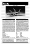
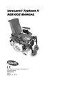
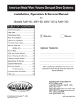
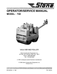
WHEN RE·ORDERING QUOTE
5110/2
LOCKHEED HYDRAULIC
BRAKE COMPANY LTD.
HYDRAULIC BRAKES
(PRIOR TO TWO LEADING SHOE)
FOR
CARS AND LIGHT
COMMERCIAL VEHICLES
SERVICE
MANUAL
One of (he Aucomotillt Producu Group
AUTOMOTIVE PRODUCTS COMPANY LTD.
SERVICE. SPARE PARTS DIVISION
P.O . BOX 14, SOUTHAM ROAD, BANBURY
Te/t:phone ~
Banbury ....21
Telecroms ' "Autoducu" Banbury. Telex
rt/.. No. 83106
London Office
AUTOMOTIVE HOUSE, LANGHAM STREET, LONDON, WIN 'AT
rt/.""o"., 01
sao 2527
rt'" No.
23+46
SERVICE
MANUAL
.;:;:h
~
•
19 6 6
C
CENUINE
HYDRAULIC BRAKES
(PRIOR TO TWO LEADING SHOE)
FOR
CARS AND LIGHT COMMERCIAL VEHICLES
INDEX
Page
SECTION
I.
DESCRIPTION AND OPERATION
I
SECTION
2.
ROUTINE ATIENTION ._.
3
SECTION
3.
ADJUSTMENTS _.•
S
SECTION
4.
OVERHAUL INSTRUCTIONS
9
SECTION
5.
BLEEDING AND FLUSHING
21
SECTION
6.
FAULT FINDING
23
ilP
One of the Automotive Products Group
SECTION I
DESCRIPTION
AND
OPERATION
SECTION
1
DESCRIPTION AND OPERATION
contact the drums. One shoe of each brake assembly
will be applied in the same sense of rotation as the drum
and is termed the" leading shoe." the other is applied
in the opposite sense of rotation and is termed" trailing ."
The braking system comprises four leading and
trailing shoe brake asemblles which are operated by fluid
pressure generated in a master cylinder. Each fronc
brake assembly has two brake shoes mounted upon an
anchor pin in the brake backplate. and a dou ble-piston
wheel cylinder is located between the free ends of the
shoes . The rear brakes are similar co those at the (ron[
except that. with car brakes. a lever mechanism is
provided (or hand brake operation ; in the Instance of
light comme rcial vehicle brakes the place of the wheel
cylinder is taken by a bisector assembly which is operated
by a transverse wheel cylinder at the rear of the backplate.
The master cylinder is connected to the brake assemblies
When the pressure on the brake pedal is released.
the brake shoe pull-off sp rings cause the brake shoes
to move away from the drums, and the wheel cylinder
pistons are thrust back to the "off" posit ion; whilst
this is occurring, flu id is displaced back to the master
cylinder ready for the next brake applicat ion .
by means of metal tubing and flexible hoses.
From the very simplified diagram of a typical braking
system (Fig. 1) it will be seen that the master cylinder.
pipeline and wheel ,cylinders form one vessel which is
filled with Lockheed Hydraulic Brake Fluid .
The master cylinder has a single piscon. whilst each
wheel cylinder has two. all pistons being provided with
rubber seals to maintain pressure and prevent loss of
fluid.
When the brake pedal is depressed. the master
cylinder piston applies a force to the fluid which. being
incompressible, is displaced through the pipes and thrusts
the wheel cylinder pistons apart until the brake shoes
2
SECTION 1
ROUTINE ATTENTION
3
SECTION
2
ROUTINE ATTENTION
(~)
(1) The fluid level in the master cylinde r or. if applicable.
in t he sepa rate supply tank. should be checked every
1,000 miles or once a month (whichever occurs first)
and replenished if necessary. Prior to unscrewing the
filler cap. clean the area around It to prevent dire
Every 5.000 miles examine brake linings and renew if
worn to less than a third of their original thickness .
Check brake drums for excessive wear and ensure
that linings are not contaminated by lubricating oil or
grease. Whilst doing this. also check for wheel
cylinder and master cylinder leakage.
entering when it is removed . The correct fluid level
is to within t in . below the bottom of the filler cap
o r ifice. G reat care should be taken not to spill any
brake fluid on the bodywork of the vehicle since this
fluid is injurious to paint. Refit the filler cap. together
with its gasket. and securely tighten . USE ONLY
GENU INE LOCKH EED SUPER 105 BRAKE FLUID
TO SPEC. S.A.E. J 1703 WHEN TOPPING UP.
(S) Brake hoses must be examined every 10.000 miles
for any signs of leakage. chafing or general deterioraation . If there is any doubt. renew the hose. It is
recommended in any case that hoses are renewed at
least every three years or ~O.OOO miles . When
checking hoses. also inspect metal pipes for chafing
or looseness.
(6) At Intervals not exceeding three years or ~.OOO
miles. or at each third change of a brake lining.
wh iche ver occurs first. renew all rubber cups and seals
throughout the system .
The addition of fluid should be required only at
extremely long intervals. and a considerable fall in the
fluid level would indicate an external leak at some
point in the system which should be traced and
rectified immediately. To check for leaks. apply firm
pressure to the brake pedal whilst an assistant
examines the units. pipes. hoses and fittings .
The special fluid used In Lockheed brakes is one of
the most important factors in the correct operation of the
hydraulic system. for no equipment will give sat isfaction
with incorrect fluid. When topping up or overhauling the
system use only the genu ine Lockheed Super 105 Brake
Fluid to Spec. S.A.E. JI703 for it lengthens the life of all
internal pares. ac.ts as an efficient lubricant and operates
satisfactorily under all extremes of temperature throughout the world. The u se o f any ot he r flu id nullifies
a ll gua ra ntees.
(2) Ensure that the air vent in the filler cap is not choked.
since blockage would cause the brakes [0 drag.
(3) Adjust the brakes before the pedal travels to w it hin
one inch of the floor without solid resistance being
felt .
~
SECTION 3
ADJUSTMENTS
5
SECTION
3
ADJUSTMENTS
----------------
In order to ensure the complete return of the piston
W ith hydraulic brakes adjustmen t is carried out
q uickly and easily with out t he aid of special too ls and as
they are balanced automatically the re is no need to jack
up all four wheels at the same time. There are several
methods of setting the clearance between the shoes and
drums but only t hose most commonly used are described
here-if these do not apply reference should be made to
the vehicle instruction manual. In all cases make sure the
hand brake is off.
In th e brake master cy lin der, it is necessary to provide
a minimum clearance between t he piston and the push
rod which operates it. so ensuring that the piston is fully
back against its stop when the pedal is released . This Is
important, since jfthe piston is prevented from returning
fully the lip of the main cup will cover the by-pass port
and prevent the escape to tank of the excess flu id drawn
in to t he cylinde r during the return stroke of the piston ;
the brakes would. therefore. drag or remain " on."
TWO-POINT CAM ADJUSTMENT
The correct pedal adjustment is set when the vehicle
is assembled and should never need aiteration.
A
minimum clearance of
nil
Jack up unt il wheel revolves freely . Turn one
adjuster as indicated by arrow "C" in Fig. 3 (only a
partial turn is required) until the wheel is locked . Now
back off the adjuster the slightest possible amount to
allow the wheel to revolve freely . Repeat this operation
with the other adjuster after which th is particular brake
is correctly adjusted .
is necessary between the
push-rod and the piston. which gives a safety margin
of t"-t" free pedal movement at the pedal pad (refer
to Fig. 2). Th is free movement can be felt if the pedal is
depressed gently by hand . Should it not be apparent. first
check to make sure that the pedal is not being fouled by a
d isplaced mat preventing the complete return of the pedal
to the" off" position. In the event of the adjustment
having been disturbed. slacken the locknut" A " (Refer
to Fig 2.) and reset the length of the push-rod extension
until the pedal can be depressed the correct amount
before the piston begins to move. Re-tighten the locknut.
Repeat the above for all brakes.
SINGLE-POINT CAM ADJUSTMEN T
It is not necessary to jack up the wheels where this
type of adjuster is fitted . As the adjuster has to slide in
the backplate to centralize itself. it is advisable to clean
off all mud around it and apply a little penetrating oil
which should be allowed to soak in .
Turn the handwheel as indicated by ar r ow" C " in
Fig . .. until the shoes are in contact with the drum . DO
NOT USE ANY FORM OF TOOL ON THE HANDWHEEL. On releas ing the handwheel the adjuster will
spring back and automatically set the correct shoe
clearance.
Repeat the above for all brakes.
It may be found that a slightly finer adjustment can be
made if an assistant holds the footbrake on whilst the
adjustment is carried out , as this will overcome the
Fi,. 2
resistance offered by the shoe pull-off spring against the
turning of the adjuster.
6
SINGLE-POINT NOTCHED DISC
ADJUSTMENT
This method is employed where a transverse wheel
cylinder is fitted on the outside of the brake backplate.
Actess to the notched disc is obtained by removing the
wheel dust cap . revealing a hole th rough the wheel and
brake drum (Fig . 5). Proceed as follows ;- Jack up until
wheel revolves freely. then turn wheel until the hole
through drum is opposite notched disc. Insert screw
driver or similar tool and turn disc until wheel is locked .
Now turn disc in opposite direction (usually about six
notches) until wheel is free to revolve again.
Fig. 3
Repeat the above for all brakes of this type.
IMPORTAN T.-It is necessary for the t ransverse
cylinder to slide on the backplate in o rder to centralise
itself when adjusting brake shoes.
Clean off all mud around it and apply a little penetrating o il. Also check the fixing nuts to see that they are
not holding the cylinder tightly against the backplate.
The correct amount of freedom will be obtained by
tightening the nuts until the double spring washers are
fully compressed and then slackening them half a turn.
2-POIN T NOTCHED DISC ADJUSTMENT
This method of adjustment consists of turning
notched discs attached to the end caps o'f an internal
wheel cylinder . thus causing the ad juster screws to
t ighten or slacken the adjustment according to the
direction of rotation.
Fig. 4
Access to the notched discs is obtained by remov ing
the wheel dust cap which reveals a hole through the wheel
and brake drum (Fig. 5). Proceed as follows ;- Jack up
until wheel revolves freely. then turn wheel until hole
through drum is oppOS ite a notched disc. Insert a screw
dr iver or similar tool and turn disc until wheel is locked .
Now tu r n disc in opposite direction (usually about 4
notches) until wheel is free to revolve again. Turn wheel
until hole is oppOSite other notched disc and repeat the
operat ion.
Repeat above for all brakes.
Fig. 5
7
SECTION 4
OVERHAUL INSTRUCTIONS
IN 0 E X
Poge
10
ROUTINE INSTRUCTIONS
MASTER CYLINDER
10
BRAKE ASSEMBLIES
WHEEL CYliNDERS
Internally·mounted type
17
Transve rse wheel cylinder and bisector
18
REMOVING AND REFiniNG A FLEXIBLE HOSE
9
20
SECTION
4
OVERHAUL INSTRUCTIONS
that the by-pass port Is clear by probing with a piece of
fine wire. The brakes will drag If the by-pass port is
dogged as pressure will build up in the system, thereby
forcing the shoes Into contact with the drums. The port Is
deliberately drilled first with a iN drill halfway and then
completed with a ' 02a N dr ill wh ich just breaks through
Int o t he bore. A peen ing o pe rat ion at the point of e ntry
Into th e bore obviates the risk of the main cu p teari ng o n
a ragged edge.
Should It be found necessary to dismantle the braking
system, I.' . master cylinder or wheel cylinders, the
operation must be carried out under conditions of
scrupulous cleanliness. Clean off the mud and grease
Dismantle on a bench
before removing the un it .
covered with a sheet of clean paper. Do not handle
the Internal parts- particularly rubbers-wit h d irty
hands. Do not swill a un it , after re moval from t he ve hicle,
In paraffin, petrol or tr ic hlorethylene as t his will ru in
rubber parts and, on d is mantling, will give a mis leading
Impression of their original condition. Place ali metal
parts In a tray of clean brake flu id to soak, afterwards dry
off with a clean , flumess cloth and layout In order on a
clean sheet of paper. Rubber parts sho uld be carefully
examined and , If th e re Is any doubt of the ir cond it ion, a
compar ison should be made with new parts. Any signs of
swollen cups or perished rubber indicate that they s hould
be renewed immediately. To ensure unfailing reliability,
It Is usually advisable to replace ali rubber parts with new
ones these being readily available in the form of Repair
Kits, containing all the rubber components reqUired for
each particular un it . The main castings may be swilled in
industrial methylated spi rit o r Loc kheed Super 105
Brake Fluid to Spec. S.A.E. J 1703 , but if spir it is us ed
all craces of the cleane r must be dried out before
assembly. In the case of the mas te r cylinder, make sure
All Intern al parts should be dipped in Lock heed
Super 105 Brake Flu id to Spec. S.A.E. J 1703. and asse mbled
wet ; wh en assembling rubber pa rts use th e fin gers
only.
Stores departments shou ld exercise special care in
hand li ng brake parts to e nsu re that no da mage is ca used
wh ich would affect t heir corre ct funct io ni ng when
assembled . Rubbers shou ld be stored in a cold, dark place
we ll re moved from any fumes.
The type of master cyli nder used var ies accord ing to
the veh icle on which It Is fi tted ; there are three main
types, two of wh ich (shown on Figs. a & 9) Incorpo rat e
tan ks t o hold the reserve of brake flu id wh ilst th e th ird
(shown on Fig. 6) is fed from a separate tank. All three
types have similar inte rnal parts and funct ion In an
Ident ical manner. Some veh icles are fitted with a tandem
8.
9.
10.
11 .
11.
O.
14.
1. BA RREL
2. PUSH·ROO
) , 800T
... CI RCLIP
S. PISTON STOP
6. SECO NDAR'I' C UP
7. PISTON
PISTON WASHER
MA IN CUP
SPRING RETAINER
SPRING
CH ECK·VALVE BODY
CHECK. VAlVE CUP
CHECK·VAlVE WASHER
2
Fig. 6
10
The purpose of th e check-valve is to prevent the
re-entry into the master cylinder of fluid pumped Into
the line during the" bleed ing " operation; th is ensures
a fresh charge of fluid at each stroke of the brake pedal
and a complete purge of air from the system .
master cylinder (a typical example of which is shown on
Fig. 10); this type of cylinder is suppl ied in two forms.
with an integral reserve tank o r fe d from a separate tank
(as illustrated) .
Description (Refer to Fig. 6) .
Kemoving the master cylinder from the vehicle.
A piston (7) is contained within the barrel (1). and
has a rubber main cup (9) sp r ing-loaded against its inner
end; between the cup and the piston a th in washer (8)
(1) In the instance of cylinde rs which are fed from a
separate su pply tank. empty fluid from the tank by
attaching a rubber tu be to a bleeder screw in one of
the wheel cylinders. slacken the sc rew one complete
turn and pump the brake pedal unt il the tank Is empt y.
is fitted to prevent the cup from being drawn into the
small feed holes drilled aroun d the piston-head . The outer
end of the piston carries a rubber secondary cup (6) and
is formed with a depression to receive the spherical end
(2) Brush away any dirt from the pipe connections.
disconnect the pipe from the end of the cylinder. and
plug the end of the pipe to prevent the entry of dirt
and/or the loss of fluid ,
of a push-rod (2). A rubber boot (3) which fits on the end
of the barre l and on th e push-rod. prevents the Intr usion
of dirt and mo isture into the cylinder.
At the e nd opposite to the push-rod. a check-valve
assembly is fitted . comprising a metal body (12) into which
a rubber cup (13) is fitted. this assembly is loaded against
a rubber valve washer (14) by the piston retur n spring (11).
(3) With the types of ~ylinder shown on Figs. 8 & 9 detach
the push-rod from the brake-pedal linkage ; with the
other type t he rubber boot may be detached from
the end ofthe cylinder. and the push-rod left attached
to the linkage.
Principle of operation.
Depressing the brake pedal causes the push-rod to
thrust the piston along the bore of the barrel. and the
fluid thus displaced lifts the lip of the cup away from the
holes in the check-valve body and passes to the brake
wheel cylinders.
(4) Unscrew the fixing bolts. detach the master cylinder
from the vehicle. and drain the remaining fluid from it.
Dismantling (Refer to Fig. 6)
(1) Depress the piston to re lieve the spring-load from
the circlip (4). remove the circlip and the piston-stop
(5). and withdraw the piston (7). the piston washer.
the main cup (9). the spring. the check-valve and
the rubber valve washer (14).
Upon removal of the load from the brake pedal . the
return spring thuses the piscon back against its stop faster
than fluid is able to return from the wheel cylinders ;
this creates a depression in the master cylinder which
draws the edge of the main cup away from the head of the
piston and allows fluid from the tank to flow through the
feed holes thus uncovered to make up the temporary
defiCiency.
(2) Remove the secondary cup (6) by stretching it over
the end of the piston. and remove the cup (13) from
the check-valve body (12).
Assembling (Refer to Fig. 6)
Meanwhile fluid returning from the wheel cylinders.
being under load from the bra ke shoe pull-off springs. lifts
(1) Using the fingers only. stretch the secondary cup (6)
on to the piston (7). with the lip facing the piston-head
(i.e .. the drilled end) .; gently work round the cup.
with the fingers. to ensure correct bedd ing. Ease the
cup (13) into the check-valve body (12) and bed it into
position with the fingers only.
the check-valve away from its seat and re-enters the
master cylin der.
When the piston is fully back against its stop. the
main cup uncovers a small by-pass port in the barrel. and
this allows the release of excess fluid to the tank. thus
permitting the pull-off springs to return the brake shoes
to the fully" off" position ; the by-pass port also com-
(2) Insert the rubber valve washer (14) into the bore of
the barrel (1). and push down until it seats squarely
against the end face of the bore.
pensates for contraction or expansion of the fluid, due to
changes in temperature, allowing fluid to flow into or
(3) Locate the spring retainer (10) on the appropriate
end of the spring (11). and bend over the tabs to
escape from the system. Should this port become blocked
any excess flu id would be unable to escape and the brakes
would consequently drag.
secure it .
Locate the check -valve assembly at the
other end of the spring.
11
pedal linkage. it should now be re-fitted . After
ensuring that the rubber boot is in position on the
push-rod . insert the end of the rod into the cylinder.
(4) Hold the barrel so that the outlet is uppermost. and
insert the spring. with the check-valve leading.
Reverse the barrel and insert the main cup (9). lip
leading. taking care not to turn back or buckle the lip.
(3) Stretch the large end of the boot onto the e nd of the
cylinder.
(5) Insert the piston
washer (8) so that
the curved edge is
towards the cup
(as shown on Fig.
(4) Check the brake pedal adjustment as detailed on
page 6.
(5) If the cylinder is of the type which is fed from a
Fig. 7
7) .
separate or a supplementary tan k, connect up the
pipe from the tank to the top of the cylinder. ensuring that the end of the pipe is first unplugged.
(6) Insert the piston
(7) into the barrel.
with the drilled
(6) Fill the supply tank as indicated in Section 2. re-fit
the filler cap (together with its gasket) and securely
tighten.
head innermost.
(7) Push the piston down the bore. locate the
piston stop (5) wit hin the bore and fit the
circlip (4) into its groove; it is MOST IMPORTANT that the circlip be correctly fitted in its
(7) Test the master cylinder by pumping the brake
pedal several times and allOWing it to return un·
assisted; after one or two applications fluid should
groove.
flow from the outlet connection.
Re-fltting the master cylinder to the Vehicle
(8) Unplug the outlet pipe. and connect it to the end of
the cylinder.
(1) Secure the master cyl inder to the vehicle by fitting
the fixing bolts and. with the types of cylinder shown
on Figs. 8 & 9. attach the push-rod to the brake pedal
linkage.
(9) .. Bleed" the system as described in Section S.
(10) Check for leaks by applying a firm pressure to the
brake pedal and. whilst maintaining the pressure.
(2) If. with the type of cylinder shown on Fig. 6. the
push-rod was previously removed from the brake
inspect the
1. FILLER PLUG
II
line" and connections.
2. GASKET
10. MAIN CUP
11 . SPRING RETAINER
J. COMBINED BARREL &
11, SPRING
... BOOT
11 . CHECK.VALVE BODY
H . CHeCK· VALVE CUP
TANK
5, CIRCLIPS
6. PUSH·ROD & PISTON STOP
15. CHECK·VAlVE WASHER
16. CRAIN PLUG
17. GASKET
ASSEMBLY
7. SECOND"R Y CUP
8. PISTON
9 . PISTON WASHER
Fig. 8
12
11 .
11.
11.
14.
1. flLLEIl CAPO
2. GASKET
l . COMBINED B"I\flEL &
TANK
... PUSH. ROO AND PISTON
STOP ASSE MBLY
S. BOOT
6. CIRCUP
7. SECONDARY CUP
8. PISTON
9. PISTON WASHER
10. MAIN CUP
n.
3
SPRING RETAINER
SPRING
CHECK·VALVE BODY
CHECK . VALVE CUP
CHECK. VALVE WASHEI\
16 GASKET
17. HEAD
lB. SHAKEPROOF WASHEflS
19. LOCKNUT
•
Fi,. 9
effect until It picked up the secondary pls[On. Further
effort would apply the brakes which are operated by the
secondary cylinder.
This type of master cylinder actually consists of twO
separate and complete hydraul ic systems so that In the
unlikely event of one system failing as the result of excessive leakage there will still remain an effective brake.
The type illustrated on Fig. 10 has a separate supply tank
usually situated under the bonnet with two Independent
compartments feeding the tWO inlet POrtS on the cylinder.
In the Integral tandem type. the tank and cylinder are
cast as one.
Should a leak occur in the secondary cylinde r the
press ure generated in the primary would fi rst dr ive the
secondary piston to the end of its stroke and then app ly
the front brake.. It is essential that the full stroke of •
tandem cylinder is utilised In order that the safety featu re
Is retained . To check this. open wheel cylinder bleeder
screw at both front and rear brakes and depress the brake
pedal. Ifall is in orde r the cylinder will prevent mo vement
before the pedal reaches the floorboard. Should the pedal
reach the floorboard either the pedal pad stem is too
short. the mat too thick or the floorboard is out of position
and the necessary correction should be made.
The tandem master cylinder. in effect. consists of twO
barrel type master cylinders in line without any direct
fluid communication between them . Each cylinder Is fed
from an Independent compartment in the supply tank and
each operates the brakes on one axle only. On depressing
the brake pedal the primary piston (13) displaces fluid
via the check valve (5) and the pipe line to the wheel
cylinders on the front axle until the shoes touch the
drums.
It is important to realise that the screw (20) is a
stop for the secondary piston and not a drain plugIt should never be removed u nless the cylinder is to be
completely dismantled. When dismantling the cylinder.
remove the circllp (11). piston (13). main cup (14) and
spring (16); then unscrew the cylinder head (33) and
remove the spring (25). thus relieving the secondary
piston of any load which would tend to damage it when
removing the stop pin (20). The secondary piston can be
withdrawn through either end of the cylinder. When
re-assembling push the secondary piston complete with
cups into position so thilt the space formed by the
reduced skirt of the piston comes opposite the stop pin
hole to ensure that the piston is not trapped when
inserting the StOP pin.
Further movement of the primary piston generates
pressure In the primary cylinder which causes the
secondary piston (22) to move forward and d is place fluid
via the check valve (29) and the pipe line to the wheel
cylinders on the rear axle. When all shoe clearances have
been taken up further effort on the pedal generates equal
pressure in both cylinders by virtue of the secondary
piston being a floating member. Thus all brakes are fully
compensated despite the fact that two separate systems
are in use. In the event of a leak occurnng in the primary
cylinder the primary piston would move forward without
13
1. VALVE ADAPTER
2. GASKET
1. CHECK-VALVE
WASHER
... CHECK·VALVE
CUP
S. CHECK . VALVE
80DY
6. CHECK_VALVE
SPRING
7. CIRCLIP
8.
,.
10.
11 .
11.
11 .
14.
15 .
16.
11.
18.
19.
20.
11 .
21.
MAIN CUP
SECONDARY CUP
STOP PIN
WASHER
SECONDARY
PISTON
23. MAIN CUP
2". SPRING RETAINER
is. SECONDARY
SPRING
8ARREL
PUSH· ROO
800T
CIRCLIP
SECONDARY CUP
PRIMARY PISTON
MAIN CUP
SPRING RETAINER
PRIMARY SPRING
SPRING RETAINER
1&. CIRCLIP
27. PISTON STOP
28. CH ECK-VALVE
SPRING
29. CHECK.VALVE
800Y
10. CHECK·VAlVE CUP
11. CHECK-VALVE
WASHER
12. GASKET
ll. CYLI NDER HEAD
Fig. 10
BRAKE
ASSEMBLIES
brakes, 'he plain one). Follow 'his wi,h the oU'e r shoe, a
second large plain washer, ' he Thackray sp r ing washer,
the smaller plain washer and lastly t he circlip. locat ing
,his in 'he groove in the end of the anchor pin. ( Note, Some assemblies have the spring washer fi t ted between
the shoulde r of 'he ancho r pin and 'he first la rge plain
washer). Fit 'he pull-off sp rings and com ple,e 'he steady
pin assem blies.
When reassembling Slotted or Hooded Shoes. after
removal fo r any reason, it is essential to realise that the
shoe with the rectang ula r hole. w hich carries the abut~
men t washer, is th e lead ing shoe and t hat with the plain
ho le is t he trailing shoe.
First, tho roughly clean all moving parts and lubricate
with LOCKH EE D Expander Lubricant with special
attention to steady pin slots and anchor pin holes in the
brake shoe webs. the abutment washer and the anchor
in it selr. Fit one of t he large plain washers to the anchor
pin and offer up th e inner shoe. (On near~side brakes. this
is usually the slotted or hooded shoe and on off-Side
Now push the slotted or hooded shoe upwa rds to
the fullest extent on its abutment washe r. The brake
drum can now be assembled .
Now spin the drum in a fo rwa rd direct io n and app ly
the brake. This will cent ralise the slotted or hooded shoe
within the drum .
Complete by adjusting the brakes until satisfactory
results are obtained.
IMPORTANT : At no time must oil or grease be
a llowed in contact with the brake
s hoe lin ings.
If contamina tion of
th is nature occurs. it is recom~
mended t ha t re-lined shoes be
fitt ed.
When re-lined brake shoes are being used. the
same make and quality of lining speCified by 'he vehicle
manufacturer (or an approved alternative) must be used
throughout. otherwise uneven braking will result despite
equal pressure being exerted on all shoes. To enable
th is to be accomplished in the easiest possible manner.
advantage should be taken of our exchange shoe scheme.
particu la rs of which are obtainable from Lockheed
stockists.
Fie. 11
14
Front Hose Connection
Front Wheel Cylinder
Shoe Adju ster
Brake Bock Plate
Fig. 12.
Fig. 13.
Typical car brake
Typical commercial brake
15
Broke Drum
8 rok" Sh"t 5prln9
""
Fig. 14. Typical car brake
Fig. 15.
Typical commercial brake
16
1. ILEEDER SCREW
1. BODY
1. lOOT
... PiSTON
S. CUP
6. CROWN SPRI NG
7. RETURN SPRING
e. CROWN SPRING
t . CUP
10. PISTON
11 . BOOT
1.
1.
1.
...
S.
t-'
6.
7.
8.
9.
10.
11 .
2
BUEDEA.
BODY
BOOT
PISTON
CU P
CROWN
RETURN
CROWN
CUP
PISTON
BOOT
SCREW
SPRING
SPRING
SPRING
10
Fig. 16.
fir. 17
The th ird type (shown on Fig. 18) Incorporates adjusters
for the brake shoes, comprising end caps into wh ich
adjuster screws are threaded : by turning these end caps,
the adjuster screws are caused to move inwards or
outwards so taking the brake shoes with them.
Typical Internally-mounted wheel cylinders are
shown on Figs . 16-18 : the first of these Is used with the
type of brake assembly shown In Fig. 13, and Its pistons
Impart thrust to the brake shoes via push rods. The
wheel cylinder shown in Fig. 17 is used with the type of
Rubber cups are loaded ag31nst the Inner faces of the
pistons by means of a return spring at each end of which a
crown spring Is located. The cylinders shown on Figs. 16 &
17 are fitted with rubber boots to prevent the intrusion
of d irt and moisture.
brake assembly shown In Figs. 12 & 14, and In th is Instance
the pistons thrust direct against the brake shoes. Both
of these wheel cylinders are non-ad justable, the brake
shoes being adjusted by cams mounted in the backplate .
1. RIVET
1.. LOCKING SPRING
1. BODY
~==~-----2
... BLEEDER SCREW
S. ADJUSTER SCREW
6. END COVER
7. PISTON
8. CUP
9. CROWN SPRtr'lG
10. RETURN SPRING
11. CROWN SPRING
11. CU P
1]. PISTON
,... I!ND COY!I\
1S. ADJUSTER SCI\EW
fir. 18
17
affect the positioning of the handbrake linkage. When the
Dismantling
hand brake is applied. the pull-rod pulls on the hand brake
If fitted. ease the rubber boots off each end of the
body. W ithdraw the pistons and expel the internal parts.
barrel and th e brakes are applied in an iden tical manner
to that described for a hydraulic application. except that
the positioning of the piscon is und istu rbed.
Assembling
(1) If applicable. ease the rubber boots on to the pistons.
Insert one piston into one end of the body · and
stretch the boot on to the body.
Removing from vehicle, dismantling, assembling
and refitting to vehicle.
(2) Insert a rubber cup. flat face leading. into the
(1) Jack up vehicle and remove road wheel and brake
drum.
opposite end of the bore and push in with a wooden
rod until it contacts the fitted piston.
(2) Disconnect fluid pipe from transverse cylinder and
(3) Place a crown spring at each end of the return spring.
plug the end of pipe to prevent the entry of dirt and
and insert these parts into the bore. followed by the
second cup (lip innermost) taking great care not to
turn back or buckle the lip.
loss of fluid.
Unscrew pull-rod from handbrake
linkage.
(3) Unscrew stop pin. remove large boot clip. ease boot
(4) Insert the second piston into the bore and stretch
off body and remove circlip.
the boot on to the body.
Unscrew hand brake
barrel assembly from draw link and remove from
(5) If applicable. fit the end covers together with the
body.
adjuS'ter screws.
Remove self-locking nuts. take cylinder off
mounting studs and extract piscon, cups and distance
piece.
(4) Withdraw the bisector. complete with packing piece.
Remove end cover (ref. 12. Fig . 21). withdraw the
These two units are used with the type of brake
assembly shown on Fig. 15; they operate together. the
transverse cylinder being mounted externally at the rear
of the backplate whilst the bisector is mounted internally
between the tips of the brake shoes. In addition to
operating by hydraulic pressure. the transverse cylinder
also incorporates hand-brake operating linkage.
STOP PIN
The transverse wheel cylinder comprises a body
containing a piston which passes through two rubber cups
HANOBRAKE
separated by a distance piece. the head of the piston
being adjacent to th e hand brake barrel; this latter part
carries a pull-rod which is connected to the hand brake
linkage.
BARREL
The bisector body houses two tappets between which
are 'assembled a fork-end carrying two segments and a
draw link which screws into a floating nut in the hand~
brake barrel.
When the footbrake is applied. fluid pressure causes
the piston to thrust against the handbra ke barrel . this
pulls on the drawlink causing the segments to roll
between the bisector tappets which are pushed outwards
and so apply the brake shoes. During this action the
hand brake barrel slides along its pull-rod and so does not
TAPPET
PIN
Fig. 19
18
fork-end assembly, push out the pivot pin (ref. 5,
Fig. 21) and separate the various items . Remove the
split pins and extract the tappets.
:?d;~:' 11:,'.~
I
RETAINERS
... SEGMENTS
S. PIVOT PIN
6, SELF. LOCKING
NUTS
7. THACKERAY
(5) When assembling the bisector, first smear all
internal parts with Lockheed Expander Lubricant.
Insert the tappets into the body, paying particular
WASHERS
8. SPRING CATCH
9, BODY
10. SPLIT PINS
attention to the illustrations to ensure correct
assembly, and retain them by fitting new split pins :
screw the adjuster wheel (16) into hollow tappet.
11. GASKET
n.
END COVER
13 . SCREW S
, ... TAPPET
15, TAPPET (ADJUSTER
EN D)
Pass fork·end over draw link. Place a sector retainer
(ref. 3, Fig. 21) on the side of each segment, so that
cranked tongue engages the locating hole. Position
the segm.ents with in the slot of the for k-end so that
16. ADJUSTER. W HEEL
3
their inner rad ii and the reta iners are In alignment
8
with the pivot-pin hole, and Insert the pin (ref. 5,
4- -
1. STOP PIN
2
<:::>
2. WAS HE R
l . BO DY
@~~4
~.",....---- 5
6
... BOOT CI.IP
(SMALL)
S. BOOT
6. BOOT CLIP
(LARGE)
5
6
2
3
7~
8
FiB. 21
Fig.21) . Insert th is assembly into the body, from the
end-cove r end , and fit the end cover and gas ket (11,
12).
9
(6) Whe n asse mb li ng the transve rse wh eel cylinder ,
7. CIRCLIP
8. HAN OBRAKE
9,
10.
11 .
11.
11.
BARREL ASSY,
PISTON
BLEEDER SCREW
CUP
DISTANCE PIECE
CUP
first fit the two rubber cups on the piston, with the
0
distance piece between them and with the lips of
the cups facing each other.
12
Insert these pares into
the bore of the body, pressing them in as far as they
will
13
go.
Smear
the
hand brake
barrel
with
Rubberlube and Insert Into the body : fit the circiip
FiB. 10
but do not fit the stop pin or boot at this stage.
19
(7) Clean bo th sides of the brake backplate and smear
the areas to be covered by the cylinder and bisector
with Lockheed Expande r Lubricanc. Place the spring
cacch on the appropriate scud in the biseccor. locate
the packing piece on the scu ds. and offer up the
bisector to the backplate.
w ise the hose may be damaged . If the obstruction cannot
be clea red the hose must be replaced by a new one.
Position the transverse
wheel cylinder at t he rear of the backplate. gu iding
the biseccor draw-link through the cencre of the
piscon. and secure the cylinder by fieeing the tWO
Thackeray washers and new self-locking nu[S to the
sc uds: tig hten the nu[S fully and then slacken back
three flats, t he assem bl y sho uld now be free to slide
on the backplate.
Fig. 22
To remove the flexible hose. adopt clie following
procedure (referring to Fig. 22. which shows a typ ical
junccion) :-
(8) Screw t he handb rake barrel assembly on to th e draw
link until finger tight , taking ca re nOt to .. cross"
the threads of the floating nut. Slacken back until a
slot In the barrel is in line wit h the scop-pin hole.
there should now be slight end play in the assembly:
If this is not present. slacken back a further half turn .
Fit the scop pin together with i[S washer: the pin
is to engage in the' handbrake-barrel sloc.
Unscrew the tube nut .. B" from the hose union
.. A." then unscrew the nut" C .. and withdraw the hose
from the brackec.
Disconnect the hose at the other end .
When refitting brake hoses ensure that there is
(9) Pack the open end of the cylinder with Rubber lube.
fit the boot over the pull-rod and onto the end of
no risk of fouling due to the steering lock of the
fron t wheels or oscillating moveme nt of t he
suspension.
the cylinder and secure it wit h t he two boot clIps.
(1 0) Re-fit t he brake d r um and the road wheel. "bleed "
the syscem and adjusc the brakes.
First aeeach the hose to the wheel cylinder (in the
case of the front brakes) or the three-way conneccion (in
(11) Connecc the pull-rod to the handbrake linkage : th e
linkage should be so adjusced as to allow s light end
play when the brakes are off.
the case of rear brakes). us ing a new gaskec. Ensure that
the hose is not tw isced or "kinked" (thiS is most
important) then pass the hose un ion" A " through the
bracket and. whilst holding the union with a spanner to
prevent the hose from turning . fit ':.he nut " C .. and the
In some cases the cause of faulty brakes may be
craced to a choked flex ible hose. Do not attempt to clear
the obstruction by any means except air pressure, other-
shakeproof washer: connect up the pipe by screWing in
the tube nut " B."
20
SECTION 5
BLEEDING
AND
21
FLUSHING
SECTION
5
AND
BLEEDING
FLUSHING
Should the fluid in the system become th ick or
.. gummy" after many yea rs in service, or after a vehicle
has been laid up for some considerable time, the system
should be drained, flushed and refilled . It is recommended
that this should be carried out once every three years.
The system should also be flushed If it has become
contam inated by the use of spurious fluid .
Pump all fluid out of the hydraulic system through the
bleeder screw of each wheel cylinder In turn . Connect
one end of a rubber tube to the bleeder screw, allowing
the other end to fall Into a concainer, unscrew one com-
plete turn and pump the brake pedal by depressing it
quickly and allowing it to return without assistance.
Repeat, with a pause in between each operation, unt il
no more fluid is ex pelled. Discard th e fluid extracted.
Fill the supply tank with industrial methylated spirit and
flush the system by pumping as described above. Keep the
supply tank replenished until at least a quart of spi r it has
bee n passed through each wheel cylinder.
Fig. 13
(2) If the master cylinder used in the system is of a type
fitted with a bleeder screw, commence at this unit.
Slacken the bleeder screw, depress the brake pedal
slowly by hand and, whilst FLUID issues and before
th e pedal reaches th e end of its stroke, tighten the
bleeder screw securely.
(3) Attach a rubber tube to a bleeder screw on one of the
wheel cylinders and allow the free end to be submerged in a little fluid in a clean glass jar (as on Fig. 23)
Open the bleeder screw one complete turn.
(-4) Depress the brake pedal slowly, allOWing it to return
Where possible, remove the supply tank and pour off
the remaining spirit.
Refill with clean Lockheed Super lOS Brake Fluid
to Spec. S.A.E. J 1703 and .. bleed" the system.
Note-If the system has become contaminated by the use of mineral
oil , etc .. the above process may not prove effective. It Is
recommended that the various units, Including the pipe line,
shou ld be dismantled and thoroughly cleaned and that all
unaSSisted, repeating this pumping action with a
rubber paru, including flex ible hoses. should be renewed . The
Slight pause between each operation. Watch th e flow
of flu id in the jar and when all air bubbles cease to
appear, hold the pedal down firmly and securely
tighten the bleeder screw .
(5) Repeat at all wheel cylinders.
(6) Where a tandem master cylinder is fitted, one front
and one rear wheel cylinder should be bled simultaneously to obtain the best purge.
contaminated fluid should be destroyed Immediately.
.. Bleeding" the system-or expelling air-is not a
routine operation and should be necessary only when
some portion of the hydraulic equipment has been
disconnected or when fluid has been dr.lned off.
(I) Fill the supply tank with Lockheed Super 105 Brake
Fluid to Spec. S.A.E. J 1703, and keep at least a quareer
full throughout the operation. Otherwise, air will be
drawn In. necessitating a fresh start.
Not
22
Flu id bled from the system should be discarded .
SECTION 6
FAULT
FINDING
23
SECTION
1.
6
FAULT FINDING
PEDAL TRAVEL EXCESSIVE
S.
BRAKES DRAG
(0) Shoes over adjusted .
(b) Shoe pull-off springs weak or broken.
(c) Pedal spring weak o r broken .
(d) Pedal to push rod adjustment Inco rrect.
(0) Handbrake mechanism seized .
(f) Wheel Cylinde! piston seized.
(g) Supply tank overfilled or filler cap vent hole
bloc ked .
_
(h) Master Cyl inder by- pass port choked.
(i) Handbrake ca bles over adjusted .
6.
BRAKES REMAIN ON
(0) Shoes over adjusted .
(b) Handbrake ove r adjusted.
(c) Pedal to push rod adjustment Inco rrect.
(d) Master Cylinde r and/or wheel cylinder cups
(Requ ires Pumping).
(0) Brake Shoes requ ire ad justing or re·lin ing if
adjustment is already at a maximum .
(b) Master Cylinder push rod requires adjusting.
(Excessive push-rod clearance).
(c) Master Cylinder requ ires replen ish ing.
(d) Leakage past main cu p in Maste r Cyl inder.
2.
PEDAL FEELS SPRINGY
(0) lin ings not ." bedded-in."
(b) Brake drums weak or cracked.
(c) Master Cy lin der fixing loose.
3.
PEDAL FEELS SPONGY
swollen , due to con tamination with mineral
oil or spurious fluid .
(0) Leakage past main cu p in Master Cylinder.
(b) Master Cylinder seco nd ary cup worn. (Air
bubbles r ise in su pply tank).
(c) Leak at one or more points in system .
(d) Brakes not properly bled .
4.
7.
BRAKES I NEFFICIENT
(0) lin ings not" bedded-in."
(b) linings greasy.
(c) li nings incorrect type.
24
UNBALANCED BRAKING
(0) Greasy linings.
(b) Distorted drum s.
(c) Front sp ring bro ke n or loose at anchorage.
(d ) Tyres unevenly inflated.
(0) Brake backplate loose on axle.
(f) Worn stee ring connections.
(g) W orn sp ring shackles.
(h) Different grades of linings fitted .
One of the Automotive Products Group
Printed In England
F I ~S