1
Operator's
Manuam
2-Cycle
MINI-TILLER
& CULTIVATOR
With Edger Attachment
Mode[ No. 316.29256
CAUTION:
Before using
this product,
read this
manual and follow a[[
safety rules and operating
instructions.
Sears, Roebuck
Espahoi,
and Co., Hoffman
Visit our website:
Estates,
www.sears.com/craftsman
P/N 769-01154 (2/04)
PRINTED IN USA
[L 60179, U.S.A.
p. 19
TABLE
OF CONTENTS
Warranty
Operating Instructions
.................................
Service Information
2
.........................
Rules for Safe Operation
2
.....................
3
Know Your Unit ............................
6
Assembly Instructions
7
......................
Maintenance and Repair Instructions ...........
12
Cleaning and Storage .......................
15
Troubleshooting
16
Specifications
Chart ......................
.............................
EPA Warranty Information
Oil and Fuel Information
Starting/Stopping
.......................
......................
Instructions
................
9
10
11
17
...................
18
Parts List ................................
Repair Protection Agreement ....
Service Numbers ...................
35
Inside Back Cover
Back Cover
Full Two-Year
Warranty
on Craftsman
Mini-Tiller
and Cultivator
For two (2) years from the date of purchase, if this Craftsman Equipment is maintained, hbricated, and tuned up
according to the instructions to the operator's manual, Sears will repair or replace free of charge any parts found to be
defective in material or workmanship. Warranty service is available free of charge by returning Craftsman equipment to
your nearest Sears Service Center. In-home warranty service is avaihble but a trip charge will apply. This Warranty
applies only while this product is in the United States.
This Warranty
does not cover:
Expendable items which become worn during normal use, such as spark plugs, air cleaners, belts, and oil filters.
• Tire replacement or repair caused by punctures from outside objects, such as nails, thorns, stumps, or glass.
• Repairs necessary because of operator abuse, including but not limited to, damage caused by objects, such as stones
or metal debris, oversized stock, impacting objects that bend the frame or crankshaft, or over-speeding the engine.
Repairs necessary because of operator negligence, including but not limited to, electrical and mechanical damage
caused by improper storage, failure to use the proper grade and amount of engine oil, or faihre to maintain the
equipment according to the instructions contained in the operator's manual.
Engine (fuel system) cleaning or repairs caused by fuel determine to be contaminated
fuel should be used within 30 days of its purchase date.
or oxidized (stale), In general,
Equipment used for commercial or rental purposes.
TO LOCATE THE NEAREST SEARS SERVICE CENTER OR TO SCHEDULE SERVICE, SIMPLY CONTACT SEARS AT
1-800-4-MY-HOML
,
This warranty gives you specific legal rights and you may also have other rights, which vary from state to state.
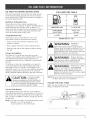
CALiFORNiA
PROPOSiTiON
65 WARNING
THE ENGINE EXHAUST FROM THIS
PRODUCT CONTAINS CHEMICALS
KNOWN TO THE STATE OF CALiFORNiA
TO CAUSE CANCER, BIRTH
OR OTHER
REPRODUCTIVE
DEFECTS
HARM.
SPARK
ARRESTOR
NOTE
NOTE: For users on U.S. Forest Land and in the
states of California, Maine, Oregon and Washington.
All U,S. Forest Land and the state of California (Public
Resources
Codes 4442 and 4443), Oregon and
Washington
require,
by law that certain
internal
combustion engines operated on forest brush and/or
grass-covered areas be equipped with a spark arrestor,
maintained in effective working order, or the engine be
constructed, equipped and maintained for the prevention
of fire. Check with your state or local authorities for
regulations pertaining to these requirements, Failure to
follow these requirements could subject you to liability or
a fine. This unit is factory
equipped
with a spark
arrestor.
If it requires replacement,
ask your LOCAL
SERVICE DEALER to install the Accessory
Part
#182747 Spark Arrestor Kit.
Thepurposeof safetysymbolsis toattractyour
attentionto possibledangers,Thesafetysymbols,
andtheirexplanations,
deserveyourcarefulattention
andunderstanding.
Thesafetywarningsdo notby
themselves
eliminate
anydanger,Theinstructions
or
warningstheygivearenot substitutes
for proper
accidentprevention
measures,
SYMBOL
SYMBOL
MEANING
DANGER:
Failure to obey a
safety warning will
result in serious injury to yourself or to
others. Always follow the safety precautions
to reduce the risk of fire, electric shock and
personal injury,
MEANING
SAFETY ALERT: Indicates
danger,
WARNING:
NOTE: Advises you of information or instructions vital to
the operation or maintenance of the equipment.
, Failure to obey a
• safety warning may
result in property damage or personal injury
to yourself or to others, Always follow the
safety precautions to reduce the risk of fire,
electric shock and personal injury,
Read the Operator's Manual(s) and follow all
warnings and safety instructions.
Failure to do so can result in serious injury to the
operator and/or bystanders.
, IMPORTANT SAFETY INSTRUCTIONS
READ ALL INSTRUCTIONS
BEFORE
OPERATmNG
WARNING:
When using the unit,
you must follow the
safety rules. Please read these instructions
before operating the unit in order to ensure
the safety of the operator and any bystanders,
Please keep these instructions for later use,
Read the instructions carefully, Be familiar with the
controls and proper use of the unit.
• Do not operate this unit when tired, iii, or under the
influence of alcohol, drugs, or medication,
Children and teens under the age of 15 must not use
the unit, except for teens guided by an adult.
• All guards and safety attachments must be installed
properly before operating the unit,
Inspect the unit before use. Replace damaged parts,
Check for fuel leaks. Make sure all fasteners are in
place and secure, Replace parts that are cracked,
chipped, or damaged in any way, Do not operate the
unit with loose or damaged parts,
Fa,ure
to obey a
safetywarning can
resultininjury
to yourselfand others,
Always followthe safetyprecautionsto
reduce the riskof fire,
electric
shock and
personal injury,
warning or caution. Attention is required in
order to avoid serious personal injury. May
be used in conjunction with other symbols
or pbtographs.
,,
Carefully inspect the area before starting the unit,
Remove all debris and hard or sharp objects such as
glass, wire, etc,
Be aware of the risk of injury to the head, hands and
feet,
Clear the area of children, bystanders, and pets. At a
minimum, keep all children, bystanders, and pets
outside a 50 feet (15 m,) radius; there still may be a
risk to bystanders from thrown objects, Bystanders
should be encouraged to wear eye protection, If you
are approached, stop the unit immediately,
Squeeze the throttle control and check that it returns
automatically to the idle position, Make all adjustments
or repairs before using unit.
SAFETY
WARNmNGS
FOR GAS UNITS
WARNmNG: flammable,
Oaso,ne
highlys
and its
vapors can explode if ignited, Take the
following precautions:
• Store fuel only in containers specifically designed and
approved for the storage of such materials.
• Avoid creating a source of ignition for spilled fuel. Do
not start the engine until fuel vapors dissipate.
• Alwaysstoptheengineandallowittocod beforefilling
thefueltank.Neverremove
thecapofthefueltank,or
addfuel,whentheengineishot.Neveroperatetheunit
withoutthefuelcapsecurely
in place.Loosenthefuel
tankcapslowlytorelieveanypressure
inthetank.
• Mixandaddfuelina dean,well-ventilated
outdoorarea
wheretherearenosparksor flames.Slowlyremove
the
fuelcaponlyafterstoppingengine.Donotsmokewhile
fuelingor mixingfuel.Wipeupanyspilledfuelfromthe
unitimmediately.
Alwayswipeunitdrybeforeusing.
Movetheunitatleast30feet(9.1m)fromthefueling
sourceandsitebeforestartingtheengine.Donot
smokeor allowsparksandopenflamesnearthearea
whileaddingfuelor operatingthe unit.
WHmLE OPERATmNG
• Never start or run the unit inside a closed room or
building. Breathing exhaust fumes can kill. Operate
this unit only in a well ventilated outdoor area.
• Wear safety glasses or goggles that are marked as
meeting ANSI Z87.1-1989 standards. Also wear
ear/hearing protection when operating this unit. Wear
a face or dust mask if the operation is dusty. Long
sleeve shirts are recommended.
• Wear heavy, long pants, boots and gloves. Do not
wear loose clothing, jewelry, short pants, sandals or
go barefoot. Secure hair above shoulder level.
• This unit has a clutch. The tines remains stationary
when the engine is idling. If it does not, have the unit
adjusted by an authorized service technician.
• Be sure the tines are not in contact with anything
before starting the unit.
• Use the unit only in daylight or good artificial light,
Avoid accidental starting. The operator and unit must
be in a stable position while starting. See
Starting/Stopping Instructions.
• Use the right tool. Only use this tool for the purpose
intended.
• Use extreme caution when reversing or pulling the unit
towards you.
• Do not overreach. Always keep proper footing and
balance. Take extra care when working on steep
slopes or inclines.
• Always hold the unit with both hands when operating.
Keep a firm grip on the grips.
Keep hands, face, and feet at a distance from all
moving parts. Do not touch or try to stop the tines
when they are rotating.
Do not touch the engine or muffler. These parts get
extremely hot from operation. They remain hot for a
short time after you turn off the unit.
Do not operate the engine faster than the speed
needed to cultivate. Do not run the engine at high
speed when you are not cultivating.
Always stop the engine when cultivating is delayed or
when walking from one cultivating location to another.
If you strike or become entangled with a foreign
object, stop the engine immediately and check for
damage. Do not operate before repairing damage. Do
not operate the unit with loose or damaged parts.
Stop and switch the engine to off for maintenance,
repair, or to install or remove the tines.
Use only original equipment manufacturer
replacement parts and accessories for this unit. These
are available from your authorized service dealer. Use
of any unauthorized parts or accessories could lead to
serious injury to the user, or damage to the unit, and
void your warranty.
Keep unit clean of vegetation and other materials.
They may become lodged between the tines and
guard.
To reduce fire hazard, replace faulty muffler and spark
arrestor, keep the engine and muffler free from grass,
leaves, excessive grease or carbon build up.
OTHER SAFETY
WARNmN(:;S
• Never store the unit, with fuel in the tank, inside a
building where fumes may reach an open flame or
spark,
Allow the engine to cool before storing or transporting.
Be sure to secure the unit while transporting.
• Store the unit in a dry area, locked up or up high
to prevent unauthorized use or damage, out of the
reach of children.
Never douse or squirt the unit with water or any other
liquid. Keep handles dry, clean and free from debris.
Clean after each use. See the Cleaning and Storage
instructions.
Keep these instructions. Refer to them often and use
them to instruct other users. If you loan someone this
unit, also loan them these instructions.
SAVE THESE
SAFETY
AND
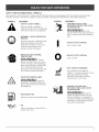
_NTERNAT_ONAL
SYMBOLS
This operator's manuaH describes safety and internationaH symboHs and pictographs that may appear on this product.
Read the operator's manuaH for compHete safety, assembHy, operating and maintenance and repair information.
SYMBOL
MEANING
SYMBOL
Indicates danger, warning, or
_ SAFETY
ALERT
SYMBOL
caution. May
be used
in conjunction
with other symboHs or pictographs.
,, THROWN OBJECTS AND
ROTATING CUTTER CAN CAUSE
SEVERE iNJURY
•
WEAR EYE AND HEARING
PROTECTION
WARNmNG: Thrown
objects and Houd noise can cause
severe eye injury and hearing Hoss.
Wear eye protection meeting ANSI
Z87.1-1989 standards and ear
protection when operating this unit.
Use a full face shield when needed.
', KEEP BYSTANDERS AWAY
WARNING:
I
0
', ON/OFF STOP CONTROL
ON / START / RUN
ON/OFF STOP CONTROL
OFF or STOP
', HOT SURFACE WARNING
Do not touch a hot muffler or
cyHinder. You may get burned. These
parts get extremeHy hot from
operation. When turned off they
remain hot for a short time.
KeepaUU
bystanders,
especiaHHy
chiHdren
and
pets,atHeast
50 feet(I5 m.)fromthe
operating
area.
UNLEADED
WARNmNG: Donot
operate without the proper guards in
pHace. Keep away from the rotating
tines.
,' WARNING - READ OPERATOR'S
MANUAL
Read the Operator's ManuaH(s)and
follow aHH
warnings and safety
instructions. FaiHureto do so can
resuHtin serious injury to the
operator and/or bystanders.
MEANING
FUEL
Always use clean, fresh unleaded fuel.
', OIL
Refer to operator's manuaH for the
proper type of oiH.
GARDEN CULTIVATORSROTATING TINES CAN CAUSE
SEVEREINJURY
WARNING:
Stop the
engine and aHHowthe tines to stop
before instaHHingor removing tines,
or before cHeaning or performing any
maintenance. Keep hands and feet
away from rotating tines.
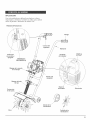
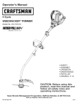
KNOW YOUR
PRODUCT
• CuHtivating sod and Hight to medium soiH
CuHtivating in garden areas, around trees, etc.
Edging
STOP/OFF (0)
Handgrip
Throttme
Controm
Handlebar
On/Off Stop
Controm
EZ Fire TM Lever
Primer Bumb
\
FuemCap
START/ON (J)
/
,
\
\
Starter Rope Grip
Nandmebar
Knob
Transport
Grip
Muffler
Transport Roller
Assembly
Edger
Wheel
Edger
Blade
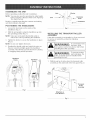
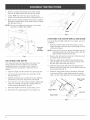
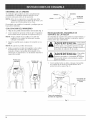
ASSEMBLING
THE UNiT
Home
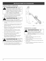
Before operating, position the unit's handlebars.
NOTE: You may also need to reposition the roller height
before using the cultivator. Refer to the Adjusting
Tine Depth section.
Nandmebar
Knob
Bott
Begin by carefully unpacMng the contents and maMng
sure that nothing is damaged.
POSiTiONiNG
"
With the unit upright, swing the handlebars up into
the operating position (Fig. 1).
NOTE: Take care not to pinch the throttle cable or
switch wires when positioning the handlebar.
3.
Tighten the knobs to secure the handlebars in place
(Fig. 2).
NOTE: Do not over-tighten
4.
NandBebars
THE HANDLEBARS
1. Loosen the two knobs on the inside of the
handlebars (Fig. 1).
2.
_
F_g. 2
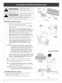
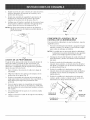
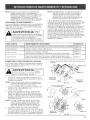
INSTALLING
ASSEMBLY
THE TRANSPORT
ROLLER
If the roller assembly is not installed, or if you ever need
to remove or reinstall it, perform the following
instructions:
WARNING:
the knobs,
Readjust the throttle cable and switch the wires so
they are smooth and tight against the handlebar
assembly. This will help prevent them from catching
or snagging during normal operation.
To
njury
from
the avoid
tines, wear
heavy gloves and a long sleeve shirt when
installing the roller assembly.
WARNING:
Topreventser ous
personal injury, the
roller assembly must be installed when
operating the unit.
NandJebar
Knobs
Handmebar
Knobs
1. With the unit on its side, place the transport roller
assembly on the underside of the tine guard (Fig. 3).
Guard
Roller
Assembly
Fig. 1
Wing Nuts &
Lock Washers
F_g. 3
2,
InstaHHa carriage bolt through each of the slotted
holes in the roller bracket and into the tine guard,
3,
On the TOP side of the tine guard, install a Hock
washer and a wing nut onto each of the bolts (Fig. 3),
4,
\
Make sure the square shoulder of the bolts is pushed
through the slotted holes in the roller bracket, Tighten
the wing nuts (Fig. 4),
\
up
NOTE: Do not over-tighten the wing nuts, Loosen the
wing nuts to adjust roller height.
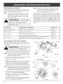
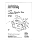
ATTACHmNG THE EDGER WHEEL
AND BLADE
To convert the mini-tiller cultivator to an edger, proceed
as follows:
®
1,
Transport
Relier
Assembmy
NOTE: It may be necessary to Jay the mini-tiller back in a
horizontal position on a flat level surface with the
upper handle touching the ground,
2,
ADJUSTmNG
TmNE DEPTH
Tine adjustment will vary depending on the type of soil
being cuItivated and how it wiII be used, GeneraIIy,
adjusting the tines to break the soiI 4 to 6 inches is
recommended for most gardens, Adjust the tines as
follows:
1, Stop the engine and disconnect the spark plug wire,
2,
Loosen (do not remove) the two wing nuts on the
tine guard (Fig, 5),
3,
Slide the roller bracket assembly down for shallower
penetration, and up for deeper tine penetration,
4,
Once the tines are in the desired position, tighten the
wing nuts, making sure that the carriage bolts are
seated properly through the bracket,
5,
If the tine depth is incorrect, repeat steps 2 to 4,
6,
Reconnect the spark plug wire and continue use,
Push the On/Off switch to Off (O) position to stop
engine and tines and disconnect spark plug to avoid
accidental starting,
Remove the click pin from each end of the tine shaft
and slide the tines off the shaft.
3, Slide the edger wheel, with the hub facing inward,
onto the right side of the tine shaft and secure with
the click pin in the inside hole (Fig, 6).
4,
Slide the edger blade with the hub facing out onto
the Heftside of tine shaft and secure with the click pin
in the inside hole (Fig. 6),
5, Guide the edger blade along a flowerbed, sidewalk,
or driveway with the edger wheel along the outside
edge, Use the edger guide line to line up edger blade,
Edger Guide
Line
Edger Wheel
Edger Blade
F_g. 6
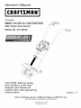
OiL AND
FUEL
MJXH_G
H_STRUCTJONS
FUEL
MIXTURE
Old and/or improperly mixed fuel are the main reasons
for the unit not running properly. Be sure to use fresh,
clean unleaded fuel. Follow the instructions carefully for
the proper fuel/oil mixture.
Definition
÷
of Bmended Fuels
Today's fueHsare often a bHendof gasoHine and
oxygenates such as ethanol, methanol, or MTBE (ether).
Alcohol-blended fuel absorbs water. As little as 1%
water in the fue[ can make rue[ and oi[ separate, it forms
acids when stored. When using alcohol-blended fuel,
use fresh rue[ (Hessthan 60 days oHd).
UNLEADED GAS
2 CYCLE OiL
1 GALLON US
(3.8 LITERS)
3.2FL OZ.
1 LITER
25 mm
Using Bmended Fuems
[f you choose to use a blended fuel, or its use is
unavoidable, follow recommended precautions:
WARNING:
• Always agitate the fuel mix before fueling the unit
Fuem Additives
The bottle of 2-cycle oil that came with your unit
contains a fuel additive which will help inhibit corrosion
and minimize the formation of gum deposits. It is
recommended that you use Craftsman 2-cycle oil with
this unit.
WARNING:
Remove fuel cap
slowly to avoid injury
from fuel spray. Never operate the unit
without the fuel cap securely, in place.
if Craftsman 2-cycle oil is unavailable, use a good 2cycle oil designed for air-cooled engines along with a
fuel additive, such as STA-B[L" Gas Stabilizer or an
equivalent. Add 0.8 oz. (23 ml.) of fuel additive per gallon
of fuel according to the instructions on the container.
NEVER add fuel additives directly to the unit's fuel tank.
Correct
Gaso,ne
extremely,
flammable. Ignited Vapors may explode.
Always stop the engine and allow it to cool
before filling the fuel tank. Do not smoke
while filling the tank. Keep sparks and open
flames at a distance from the area.
, Drain the tank and run the engine dry before storing
the unit
. For proper engine
• operation and
maximum reliability, pay strict attention to
the oil and fuel mixing instructions on the
2-cycle oil container. Using improperly mixed
fuel can severely damage the engine.
(95ram)
_'I[X[NG RATIO - 40:1
• Always use the fresh fuel mix explained in your
operator's manual
Using
TABLE
WARNING:
Add fuelina dean,
wellventilated
outdoor area,Wipe up any spilled
fuel
until fuel vapors dissipate.
NOTE: Dispose of the old fuel/oil mix in accordance to
Federal, State and Local regulations.
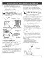
FiLLiNG
THE FUEL TANK
Make sure the cultivator is in a horizontal position when
filling or adding fuel to the tank.
Fuel Mi×ture
Thoroughly mix the proper ratio of 2-cycle engine oil
with unleaded gasoline in a separate fuel can. Use a 40:1
fuel/oil ratio. Do not mix them directly in the engine fuel
tank. See the Fuel Mixture Table for specific gas and oil
mixing ratios.
NOTE: One gallon (3.8 liters) of unleaded gasoline mixed
with one 3.2 oz. (95 ml.) bottle of
2-cycle oil makes a 40:1 fuel/oil ratio.
Rg. 7
WARNING:
Operateth,s
un,t
only,na
vvellventilated
outdoor
OFF Co)
area,Carbon monoxide exhaustfumes can be lethal
in
a confinedarea,
@
WARNING:
Avoid accidental starting.
Make sure you are in the
starting position when pulling the starter rope
(Fig. 10). To avoid serious injury, the operator and unit
must be in a stable position while starting.
ON (I)
Throttle
ControJ
F_g.8
STARTING
iNSTRUCTiONS
Mix gas with oil. Fill fuel tank with fueFoil mixture.
See Oil and Fuel Mixing Instructions.
2,
Make sure the On/Off Stop Control is in the ON [m]
position (Fig. 8).
Primer
Bulb
Fully press and release the primer bulb 10 times,
slowly. Some amount of fuel should be visible in the
primer bulb and fueHHines(Fig. 9). [f you can't see
fuel in the bulb, press and release the bulb as many
times as it takes before you can see fuel in it.
TM
Push the blue EZ Fire
Lever towards the primer
bulb until it clicks and locks into place (Fig. 9).
ii "
ii ii
5.
EZ Fire TM
Lever
Lay the unit on the ground horizontally, with the ends
of the handles resting on the ground (Fig. 10).
Put your free hand on the fuel tank to stabilize the
unit. With your other hand, pull the starter rope out
with a controlled and steady motion until the
engine attempts to start. Repeat until the engine
starts.
NOTE: The unit uses the Incredi-PulF M starting system,
which significantly reduces the effort required to
start the engine. You must pull the starter rope out
far enough to hear the engine attempt to start.
There is no need to pull the rope briskly-- there is
no harsh resistance when pulling. Be aware that
this starting method is w_stly different from (and
much easier than) what you may be used to.
7.
F_g. 9
Starting
When the engine starts, squeeze the throttle control
for 15 to 30 seconds. This will warm up the unit. The
EZ Fire TMLever will click off automatically
when
you squeeze the throttle control.
............
mFooo
The engine does not start, go back to step 3.
................
mFooo
The engine stops while you are squeezing the
throttle, go back to step 4.
mFooo
The engine stops before you squeeze the throttle
control, hold the throttle control and pull the starter
rope until the trimmer starts.
NOTE: If you are having trouble starting the unit or are
operating in extreme temperatures (below 40° F,
above 90° F), refer to the Troubleshooting section.
STOPPING
iNSTRUCTiONS
1. Release your hand from the throttle control. Allow the
engine to cool down by idling,
2.
Put the On/Off Stop Control in the OFF (O) position.
Fig. 10
10
Position
OPERATmNG
TraPS
WARNmNG:
Dress propedy to
reduce the riskof
injury when operating this unit. Do not
wear Hoose cHotNng orjeweHry. Wear eye
and ear/hearing protection. Wear heavy
Hong pants, boots and gHoves. Do not wear
short pants, sandaHs or operate barefoot.
Move the cultivator to the work area prior to starting the
engine. Transport the cultivator by pushing it on its
roller wheel or by carrying it by the transport grip.
Transport
Grip
WARNmNG: To
prevent serious
persona] injury,
never pick-up or carry the unit while the
engine is running.
2.
Start the unit by foHHowingthe Starting Instructions
3.
With the engine running and the tines off the ground,
depress the throttle control to increase the engine speed.
4.
HoHding both of the handHebar grips firmHy, showily
Hower the cuHtivator untiHthe tines make contact with
the ground (Fig. 11).
5.
As cuHtivating action begins, puHHback on the
cuHtivator so that the tines can penetrate the ground.
6.
Once the ground has been broken, continue at a
moderate pace untiHyou are famiHiarwith the controHs
and the handHing of the cuHtivator.
7.
To improve the depth of cuHtivation, puHHback on the
unit as it moves forward to drive the tines deeper
into the ground.
WARNING:
To
prevent serious
personaH injury, use
extreme caution when reversing
or pulling the unit towards you.
Fig, 11
TRANSPORTING
THE
UNIT
WARNING:
To
preventser ous
personaH injury,
aHways stop the engine when operation is
deHayed or when transporting the unit from
one Hocation to another
1. Stop the engine.
2. Slide the roller bracket assembly all the way down.
3. TiHtthe unit back untiH the tines dear the ground.
8_
If the tines are digging too deep or not deep enough,
adjust them according to Adiusting Tine Depth.
4.
Push or puHH
the unit to the next Hocation.
5.
If you need to move the unit over Hongdistances, use
11
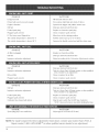
MAmNTENANCE
SCHEDULE
Perform these required maintenance procedures at the
frequency stated in the table. These procedures should
also be a part of any seasonal tune-up.
NOTE: Some maintenance procedures may require
special tools or skills. If you are unsure
about these procedures, take your unit to a
Sears Parts & Repair center or other qualified service dealer.
WARNING:
To prevent serious
inJury, never perform
maintenance or repairs with unit running.
Always service and repair a cool unit.
Disconnect the spark plug wire to ensure that
the unit cannot start.
NOTE: Maintenance, replacement, or repair of the emission
contro[ devices and system may be performed by
any non-road engine repair establishment or a
Sears parts and repair service center.
[n order to assure peak performance of your engine,
inspection of the engine exhaust port may be necessary
after 50 hours of operation. [f you notice lost RPM, poor
performance or general lack of acceleration, this service
may be required. [f you feel your engine is in need of this
inspection, refer service to a Sears Parts & Repair center
or other qualified service dealer. DO NOT attempt to perform this process yourself as engine damage may result
from contaminants involved in the cleaning process for
the port.
FREQUENCY
MAINTENANCE
Before starting engine
Fill fuel tank with fresh fuel mix
Page 9
Every 10 hours
Clean and re-oil air filter
Page 13
Every 25 hours
Check and clean spark arrestor
Check spark plug condition and gap
Page 14
Page 15
Every 50 hours
Inspect exhaust port and spark arrestor screen for clogging or
obstruction to assure maximum performance levels
Page 14
TJNE REMOVAL
REQUIRED
REFER TO
AND REPLACEMENT
" TiRe
WARNING:
To
prevent serious
injury, always wear
TiRe
heavy gloves when handling the tines.
1. Put the On/Off Stop Control in the STOP (O) position
and disconnect the spark plug boot from the plug.
NOTE: It may be necessary to lay the cultivator back in a
horizontal position on a flat level surface with the
handles touching the ground.
2.
3.
4.
Remove the click pin from each end of the tine shaft.
Slide the tines off of the shaft (Fig. 12a).
Clean and oil the shaft.
"A" TiRe
Cultivator
Front
Click
Fig. 12a
Hubs oR back side
When you are reinstalling tines, lay out the tines and
compare them to those shown in Figure 12b. Note
specifics about each tire: its hub, curvature and
lettering ("A" or "B"). This will help make sure that
you are placing the correct tines un the correct order.
NOTE: If you look closely, you can see a slight curvature
in the tire tips. These curves should point toward
the front of the cultivator when the tines are
installed. Figure 12b shows the curve in each tire.
5.
Pin
Hubs
Hubs
Using Figures 12a and 12b for reference, slide on the
new tines with the hubs facing outward.
the cultivator from the front.
6_
12
Secure the new tines to the shaft with click pins. It
may be necessary to wash the dirt off the tines and
shaft to help during this entire process.
Cultivator
Front
"A" Time
Fig. 12b
AIR FILTER
Removing
MAINTENANCE
the Air Filter/Muffler
WARNING:
Cover
To
avoid
serious
personal injury,
always turn the unit off and allow it to cool
before you clean or service it.
1.
2.
Remove the four (4) screws secuhng the air
filter/muffler cover (Fig. 13). Use a flat blade or # T20
Torx bit screwdriver.
Air Filter
J
_
Pull the cover from the engine. Do not force.
Inside Muffler
Cover
Fig. 14
EZ Fire TM
Lever
ScFews
Screws
/
Fig. 15
SPARK
Fig. 13
ARRESTOR
MAINTENANCE
1.
Remove the air filter/muffler cover. Refer to
Removing the Air Filter/Muffler Cover.
Clean and re-oil the ak filter every 10 hours of operation.
[t is an important item to maintain. Failure to maintain the
air filter will VOID the warranty.
1. Remove the air filter/muffler cover. Refer to the
Removing the Air filter/Muffler Cover section.
2. Remove the air filter from inside the air filter/muffler
cover (Fig. 14).
2.
Locate the muffler front and the two (2) bolts securing
it to the engine (Fig. 16). Remove the two (2) bolts
using a flatblade screwdriver or 5/16-inch socket or
nut driver. Pull the muffler off of the engine.
3.
Wash the filter in detergent and water (Fig. 14). Rinse
the filter thoroughly. Squeeze out excess water.
Allow it to dry completely.
NOTE: If the exhaust gasket is torn or damaged, replace it
with a new gasket before you reassemble the muffler.
4.
Apply enough SAE 30 oil to lightly coat the filter (Fig. 15).
5.
Squeeze the filter to spread and remove extra oil (Fig. 15).
6.
Replace the air filter inside the muffler cover (Fig. 14).
Cleaning
the Air Filter
NOTE: Operating the unit without the air filter and cover
assembly will VOID the warranty.
Reinstalling
the Air filter/Muffler
4.
Insert the four (4) screws into the holes in the air
filter/muffler cover (Fig. 13) and tighten. Use a flat
blade or # T20 Torx bit screwdriver. Do not over
tighten. Do not force.
Using a small flatblade screwdriver, carefully pry up
the spark arrestor from the recessed hole (Fig. 17).
Remove the spark arrestor from the muffler.
5. Clean the spark arrestor with a wire brush. Replace it if it
is damaged or if it can't be cleaned thoroughly (Fig. 17).
6.
Reinstall the spark arrestor by pressing it into the
recessed hole on the muffler's back side. Make sure
it fits tightly against the muffler and is not raised up.
7.
Place the exhaust gasket against muffler's back side.
Align the gasket bolt holes with the bolt holes in the
muffler. While holding exhaust gasket in place, insert
the bolts into the muffler's front side (Fig. 16).
Cover
1. Place the air filter/muffler cover over the back of the
carburetor and muffler.
2.
3. Turn the muffler over to the back side and locate the
exhaust gasket. Remove the muffler gasket from the
muffler (Fig. 16).
13
8.
9.
Place the muffler (with the exhaust gasket in piace and
bolts inserted}, against the engine, aIigning the bolt
holes. Tighten the boJts to secure the muffler to the
engine. If using a torque wrench, torque to:
80-90 inAb. (9-10.2 N_rn)
Reinstall the air filter/muffler cover.
WARNING:
uf
themuffler
isnot
tightened securely', it
could fall off causing damage to the unit and
oossible serious personal injury.
Spark
Arrestor
Exhaust
Gasket
Adjust
mdle Speed
Adjuster
The unit will still run
during idle speed
adjustments.
Wear protective clothing and
observe all safety instructions to prevent
serious personal injury.
If after checking the fuel mixture and cleaning the air
filter the engine still will not idle, adjust the idle speed
screw as follows:
1. Start the engine and let it run for about 2-3 minutes
at a high speed (full throttle) to warm up. Refer to the
Starting/Stopping Instructions.
NOTE: Ensure the tines are not in contact with the
ground when adjusting the idle.
2.
Release the throttle control and let the engine idle. If
the engine stops, insert a small phillips or flat blade
screwdriver into the hole in the muffler cover (Fig. 18).
Turn the idle speed screw clockwise 1/8 of a turn at
a time (as needed) until the engine idles smoothly.
NOTE: The tines shouJd not rotate during engine idJe.
3.
Muffler
- Front Side
Muffler
- Back Side
Fig. 16
Spark Arrestor
Flatbmade
Screwdriver
If the tines rotate when the engine idles, turn the idle
speed screw counterclockwise
1/8 of a turn at a
time (as needed), to reduce idle speed.
Checking the fuel mixture, cleaning the air filter, and
adjusting the idle speed screw should solve most engine
problems. If not and all the following are true:
• The engine will not idle
• The engine hesitates or stalls on acceleration
• There is a loss of engine power
Have the carburetor adjusted by a Sears Parts & Repair
center or other qualified service dealer.
\
Spark
Arrestor
Muffler - Back Side
Fig. 17
CARBURETOR
ADJUSTMENTS
[dmeSpeed Adjuster
The engine's idle speed adjuster is adjustable through
the air filter/muffler cover (Fig 18).
NOTE: Careless adjustments can seriously damage your
unit. A Sears Parts & Repair center or other
qualified service dealer should make carburetor
adjustments.
Check
Fuel Mixture
Old and/or improperly mixed fuel is usually the reason
for the unit not running properly. Drain and refill the tank
with fresh, properly mixed fuel prior to making any
adjustments. Refer to Off and Fuel Information.
Clean
Air Filter
The condition of the air filter is important to the operation
of the unit. A dirty air filter will restrict air flow and
change the air/fuel mixture. This is often mistaken for an
out of adjustment carburetor. Check the condition of the
air filter before adjusting the idle speed adjuster. Refer to
Air Filter Maintenance.
14
Fig. 18
REPLACmNG
THE
SPARK
PLUG
LONG TERM STORAGE
Use a Champion RDJ-7Y spark plug. The correct air gap
is 0.020 in. (0.5 mm). Remove the plug after every 25
hours of operation and check its condition.
1. Stop the engine and allow it to cool. Grasp the plug
wire firmiy and puii the cap from the spark piug.
If you plan to store the unit for an extended time:
1. Drain all fuel from the fuel tank into a container. Do
not use fuel that has been stored for more than 60
days. Dispose of the old fuel in accordance to local
regulations.
2.
Ciean dirt from around the spark piug. Remove the
spark piug from the cyiinder head by turning a 5/8 in.
socket counterciockwise.
2. Start the engine and allow it to run until it stalls. This
ensures that all fuel has been drained from the
carburetor.
3.
Repiace cracked, fouled or dirty spark pIug. Set the air
gap at 0.020 in. (0.5 mm) using a feebr gauge (Fig. 19).
3. Allow the engine to cool. Remove the spark plug and
put 1 oz. (30 ml) of high quality motor oil into the
cylinder. Pull the starter rope slowly to distribute the
oil. Reinstall the spark plug.
NOTE: Remove the spark plug and drain all of the oil
from the cylinder before attempting to start the
unit after storage.
0.020 in,
(0.5 ram.)
4.
Thoroughly clean the unit and inspect for any loose
or damaged parts. Repair or replace damaged parts
and tighten loose screws, nuts or bolts. The unit is
ready for storage.
TRANSPORTmNG
Fig. 19
,
Allow the engine to cool before transporting.
WARNING:
°
Secure the unit while transporting.
electrodes.
the cylinder.
°
Do not sand Mast,
scrape or clean
Grit in the engine could damage
Drain the fuel tank before transporting.
Tighten fuel cap before transporting.
MOVING
4.
Install a correctly-gapped spark plug in the cylinder
head. Turn the 5/8 in. socket clockwise until snug.
If using a torque wrench torque to:
110-120 in.qb. (12.3-13.5 N,m)
THE UNIT
1. Allow the unit to cool before moving.
2.
Loosen the knobs on the handlebar.
3.
Fold the handlebars down as shown (Fig. 20).
Tighten the knobs.
Do not over tighten.
Handlebar
CLEANmNG THE
•
UNIT
Use a small brush to clean off the outside of the unit
and to keep the air vents free of obstructions.
Do not use strong detergents or petroleum based
cleaners, like kerosene. Some household cleaners
contain aromatic oils such as pine and lemon that
can damage the plastic housings or handles. Wipe
off any moisture with a soft cloth.
Fig. 20
STORAGE
•
Never store a fueled unit where fumes may reach an
open flame or spark.
Allow the engine to cool before storing.
Store the unit in a locked up area to prevent
unauthorized use or damage.
•
•
4.
Either carry the unit by the shaft tube grip or grasp
the center of the handlebar to use it as a carrying
handle.
After the unit has been moved, reposition the
handlebars and continue operation.
Store the unit in a dry, well-ventilated area.
Store the unit out of the reach of children.
15
CAUSE
ACTION
Empty fueHtank
Fill fueHtank with new fueH
Primer buHbwasn't pressed enough
Press primer buHbfully and showily 10 times
Engine is flooded
Squeeze the trigger and pull the starter rope
OHdfueH
Drain gas tank and add fresh fuel
FouHed spark pHug
Replace or clean the spark plug
Mugged spark arrestor
Clean or replace spark arrestor
EZ Fire Heverwasn't flipped/set
Move lever to the starting position
The outside temperature
is bellow 40 ° F
Pull the starter rope up to 10-15 times
The outside temperature
is above 90 ° F
Squeeze the throttle control and pull the starter rope
CAUSE
ACTION
Air fiHteris pHugged
Replace or clean the air filter
OHdfueH
Drain gas tank and add fresh fuel
Improper carburetor adjustment
Adjust according to the Carburetor Adjustments
CAUSE
OHdfueH
ACTLON
Drain gas tank and add fresh fuel
Improper carburetor adjustment
Take to a Sears Parts & Repair center or other qualified
service dealer for an adjustment
section
Clean or replace the air filter
Mugged spark arrestor
Clean or replace spark arrestor
CAUSE
ACTION
OHdfueH
Drain gas tank and add fresh fuel
Improper carburetor adjustment
Take to a Sears Parts & Repair center or other qualified
service dealer for an adjustment
FouHed spark pHug
Replace or clean the spark plug
Mugged spark arrestor
CuHtivator tines bound with debris
Clean or replace spark arrestor
Stop the unit, switch the On/Off Stop Control to
STOP, clean and remove any debris binding the tines
CAUSE
ACTION
Spark plug gap is too small/close
NOTE:
For repairs
Repair
16
beyond
center
the minor
Adjust gap to 0.020 inch (0.50 mm)
adjustments
(1 800 4 M%HOME
listed
®) or other
above,
qualified
contact
service
your
dealer
nearest
Sears
Parts
for an adjustment.
&
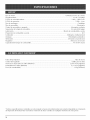
EngineType .................................................................................................
Air-Cooied,
2-Cycie
Dispiacement ..............................................................................................................................................................
31 cc
Idie Speed RPM .........................................................................................................................................
2,600-3,600 rpm
Operating RPM ...................................................................................................................................................
7,800+ rpm
Ciutch Type .........................................................................................................................................................
CentdfugaH
Ignition Type ..........................................................................................................................................................
Electronic
On/Off Stop Control .......................................................................................................................................
Rocker Switch
Spark Plug Type ....................................................................................................................................
Champion RDJ-7Y
Spark Plug Gap ..................................................................................................................................
0.020 inch (0.50 mm)
Lubrication ...................................................................................................................................................
Fuel/Oil Mixture
Fuel/Oil Ratio ..................................................................................................................................................................
40:1
Carburetor .......................................................................................................................................
Diaphragm, All-Position
Starter .................................................................................................................................................................
hcredi-Pull
Muffler .....................................................................................................................................................
Baffled with Guard
Throttle ............................................................................................................................................................
Fuel Tank Capacity .................................................................................................................................
Drive Shaft Tube ..................................................................................................................................................
Throttle Control ........................................................................................................................................
Cultivating Path Width (Maximum) .......................................................................................................
Cultivating Depth (Maximum) .................................................................................................................
Approximate Weight (no fuel) .........................................................................................................................
Spring Return
14 ounces (415 ml)
Steel Tube
Finger-Tip Trigger
9 inches (22,86 cm)
5 inches (12.7 cm)
26 lb. (12 kg)
_All specifications are based on the latest product information available at the time of printing. We reserve the right to
make changes at any time without notice.
17
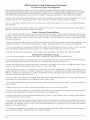
EPA Emission
ControJ
Your Warranty
Rights
Warranty
Statement
and Obligations
The Envkonmentd Protection Agency and Sears are pleased to explain the emission control system warranty on your
2002 and later small off-road engine, New small off-road engines must be designed, built and equipped to meet stringent
anti-smog standards, Ryobi must warrant the emission control system on your small off-road engine for the periods of
time listed below provided there has been no abuse, neglect or improper maintenance of your small off-road engine,
Your Emission control system may include parts such as the carburetor or fueNnjection system, the ignition system, and
catalytic converter, Also included may be hoses, belts, connectors and other emission-related assemblies,
Where a warrantable condition exists, Sears will repair your small off-road engine at no cost to you including diagnosis,
parts and labor,
The 2002 and later small off-road engines are warranted for two years, If any emission-related
defective, the part will be repaired or replaced by Sears.
part on your engine is
Owner's Warranty
Responsibilities
° As the small off-road engine owner, you are responsible for the performance of the required maintenance listed in your
operator's manual, Sears recommends that you retain all receipts covering maintenance on your small off-road engine,
but Sears cannot deny warranty solely for the lack of receipts or for your failure to ensure the performance of all
scheduled maintenance,
As the small off-road engine owner, you should however be aware that Sears may deny you warranty coverage if your
small off-road engine or a part has failed due to abuse, neglect, improper maintenance or unapproved modifications,
You are responsible for presenting your small off-road engine to a Sears authorized service center as soon as problem
exists, The warranty repairs should be completed in a reasonable amount of time, not to exceed 30 days,
If you have any questions regarding your warranty rights and responsibilities,
you should call 1-800-4-MY-HOME,
Manufacturer's
Warranty
Coverage
, The warranty period begins on the date the engine or equipment is delivered to the retail purchaser,
• The manufacturer warrants to the initial owner and each subsequent purchaser, that the engine is free from defects in
material and workmanship which cause the failure of a warranted part for a period of two years,
Repair and replacement of warranted part will be performed at no charge to the owner at an authorized Sears service
center, For the nearest location please contact Sears at: 1-800-4-MY-HOME,
, Any warranted part which is not scheduled for replacement, as required maintenance or which is scheduled only for
regular inspection to the effect of "Repair or Replace as Necessary" is warranted for the period, Any warranted part
which is scheduled for replacement as required maintenance will be warranted for the period of time up to the first
scheduled replacement point for that part,
The owner will not be charged for diagnostic labor which leads to the determination
If the diagnostic work is performed at an authorized Sears Service Center,
• The manufacturer
under warranty,
is liable for damages to other engine components
that a warranted part is defective,
caused by the failure of a warranted
part still
° Failures caused by abuse, neglect or improper maintenance are not covered under warranty,
• The use of add-on or modified parts can be grounds for disallowing a warranty claim, The manufacturer is not liable to
cover failures of warranted parts caused by the use of add-on or modified parts,
, In order to file a claim, go to your nearest authorized Sears Service Center, Warranty service or repairs will be provided
at all authorized Sears Service Centers,
• Any manufacturer approved replacement p[art may be used in the performance of any warranty maintenance or repair
of emission related parts and will be provided without charge to the owner, Any replacement part that is equivalent in
performance or durability may be used in non-warranty
maintenance or repair and will not reduce the warranty
obligations of the manufacturer,
° The following components are included in the emission related warranty of the engine, air filter, carburetor,
lines, fuel pick up/fuel filter, ignition module, spark plug and muffler,
18
primer, fuel
mNDmCE DE CONTENmDOS
Instrucdones
de operaciOn ..................
19
Instrucdones
de mantenimiento
Uamadas a apoyo aHcHiente .................
19
Normas para una operation segura ...........
Conozca su unidad ........................
20
23
Limpieza y aHmacenamiento .................
Cuadro de soHudOn de proMemas ............
32
33
Especificadones
Lista de Piezas
34
35
Instrucciones de ensamble
24
GarantJa .................................
..................
InformatiOn dell aceite y dell combustiMe
Instrucdones
.......
de arranque y apagado ..........
GarantJa
26
27
y reparaciOn
28
,,,
...........................
...........................
EPA GarantJa .............................
29
37
Cobertura de Gastos de Reparaciones .........
39
Numeros de Servido .............
Contraportada
de macumtivadora/bordeadora
Craftsman
de dos
a_os
Por un pedodo de dos (2) anos a partir de Hafecha de compra, con HacondiciOn de que a este equipo Craftsman se He
reaUizaeHmantenimiento, HaHubricaciOn y ajustes de acuerdo con las instrucciones que aparecen en el manual del
operador', Sears Ilevara a cabo reparaciones o reemplazos necesarios sin cargo cualquiera de las piezas que resulten
defectuosas en sus materiales o fabricaciOn, El servicio de garantia esta disponible sin cargo si Ileva su equipo Craftsman
al Centro de Servicio Tecnico de Sears mas cercano,EI servicio de garantia a domicilio esta disponible pero se aplicara un
cargo de traslado. Esta garantia es valida unicamente mientras el producto se encuentre dentro de los Estados Unidos,
Esta garantia no cubre:
Articulos de duraciOn limitada que sufren desgaste bajo condiciones
encendido, purificadores de aire, correas y filtros de aceite,
normdes de usol, tales como bujias de
° Reemplazo o reparaciOn de neumaticos debido a pinchaduras causadas por objetos externos, tales como clavos,
espinas, tocones o vidrio,
° Reparaciones necesarias debido al abuso del operador, induyendo pero sin limitarse a dano causado por objetos,
tales como piedras o desechos de metal, troncos de un tamano demasiado grande, objetos que hacen impacto que
puedan doblar la estructura o el carter o puedan sobreacelerar el motor,
° Reparaciones necesarias debido a negligencia del operador, incluyendo pero sin limitarse a danos electricos y
mecanicos causados por almacenamiento incorrecto, falla en la calidad o cantidad del aceite de motor utilizado, o
falla para mantener el equipo de acuerdo con las instrucciones contenidas en el manual del operador',
° Limpieza o reparaciones del (sistema de combustible del) motor causadas por combustible que se encontro que
estaba contaminado u oxidado (vencido), En general, el combustible deberia ser utilizadodentro de los 30 dias
posteriores a la fecha de compra.
° Equipos utilizados para fines comerciales o de alquiler,
PARA UBICAR EL CENTRO DE SERVICIO TECNICO SEARS MAS CERCANO O PARA PROGRAMAR EL SERVICIO
TECNICO, SIMPLEMENTE COMUNiQUESE CON SEARS AL TELEFONO 1-800-4-MY-HOME(_),
Esta garantia le otorga derechos legales especificos y tambien
un estado a otro,
usted puede tener otros derechos, los cuales varian de
PARACHISPAS
NOTA: Para mos usuarios
PROPOSICION
eri tiel"ras forestames de mos
65 DE CALIFORNIA
LAS EMIStONES DEL MOTOR DE ESTE
PRODUCTO CONTIENEN SUBSTANCIAS
QUIMICAS QUE EL ESTADO DE
CALIFORNIA CONOCE COMO CAUSANTES
DECANCER, DEFECTOS DE NACIMIENTO
U OTROS DANOS REPRODUCTIVOS.
19
SIMBOLO
SIGNIFICADO
PEUGRO" • advertencia
E,ooobedeoer
de ooa
adecuadas de prevenciOn de accidentes.
SIMBOLO
SIGNIFmCADO
ALERTA DE SEGURmDAD:
ADVERTENCmA:
EUoo
seguuruna
advertenda de seguridadpuede condudr a
que usted u otraspersonas suffanbsiones.
Siga sbmpre bs precaudones de segundad
para redudr eUrbsgo de incendio,descarga
eUectdcay bsiones personabs.
indica peHgro, advertencia o precauciOn,
Debe prestar atenciOn para evitar sufrir
graves lesiones personales, Puede set
utilizadojunto
con otros simbolos o figuras,
NOTA: Le ofrece informacion o instrucciones que son
esenciales para la operacion o mantenimiento
dei equipo.
PRECAUCmON:
EUno seguir
una
advertenda de seguridad puede condudr a
dano patrimoniaUo a que usted u otras
lpersonas sufranbsiones personabs. Siga
Sl TIENE PREGUNTAS,
LLAIVlE AL
1-800-4-MY-HOME
,, IMPORTANTE
LEA TODAS LAS INSTRUCCIONES
LA OPERACION
INFORMACION
ANTEST
DE
• Lea todas las instrucciones con cuidado. Conozca
bien los controles y el uso correcto de la unidad.
No opere esta unidad siesta cansado, enfermo, o bajo
los efectos del alcohol, drogas o medicamentos.
Los ninos y los adolescentes menores de 15 anos no
deben operar ias unidades, excepto pot los
adolescentes guiados pot un adulto.
Inspeccione la unidad antes de utilizarla. Cambie las
partes danadas. Verifique si existen perdidas de
combustible. Asegurese de que los sujetadores esten
bien coiocados y asegurados. Cambie ias partes que
esten quebradas, cascadas o danadas de cualquier
forma. No opere esta unidad con piezas flojas ni
danadas.
o Tenga en cuenta ei riesgo de lesiones en Jacabeza, manos
y pies.
• Aleje a todos los ninos, espectadores y animales
domesticos. Mantenga a todos los ninos,
espectadores y animales domesticos a un radio de
pot io menos 50 pies (15 m); aun asi, puede existir un
riesgo de objetos despedidos contra los
espectadores. Debe sugerir a los espectadores que
usen proteccion ocular. Si alguien se le acerca, pare la
unidad de inmediato.
2O
DE SEGURIDAD
,,
• Optima ei control dei reguiador y verifique que regrese
automaticamente a la posicion de minima. Haga todos
los ajustes o reparaciones antes de usar ia unidad.
ADVERTENCIAS
DE SEGURIDAD
UNIDADS A GASOLINA
PARA LAS
ADVERTENCJA:
La gasolina
es muy
inflamabb y susgases pueden e×plotar
sise
encienden.Tome lassiguientes
precauciones:
Guarde el combustible en envases que hayan sido
disenados y aprobados para el almacenamiento de
dichos materiales.
• Antes de llenar el tanque de combustible, apague
siempre el motor y espere que se enfrie. No retire
nunca la tapa del tanque de combustible ni cargue
combustible mientras el motor este caliente. No opere
nunca la unidad sin la tapa del combustible colocada
firmemente en su lugar. Afloje la tapa del combustible
lentamente para disipar la presion del tanque.
Evite crear una fuente de encendido pot combustible
derramado. No arranque el motor basra que se hayan
disipado los vapores del combustible.
• Mezcb y cargue eI combustibb en un area exterior
bbn ventiiada donde no haya chispas ni llamas, Quite
bntamente la tapa deI combustibb solo despues de
apagar eI motor, No fume mbntras carga o mezcla eI
combustibb. Limpb de inmediato todo eI combustibb
que se haya derramado.
• Abje la unidad a por Io menos 9,1 m (30 pies) deI lugar
de carga de combustibb antes de arrancar eI motor,
No fume, mantenga las chispas y las llamas abbrtas
bjos deI area mbntras carga eI combustibb u opera la
unidad,
DURANTE
LA OPERAC_ON
° No arranque ni opere la unidad en una saB o edificio
cerrado. Los gases de escape de monoxido de
carbono pueden ser btabs en un area cerrada, Opere
esta unidad solo en un area exterior bien ventilada,
• Use bntes o galas de protecciOn que cumplan con las
normas ANSI Z87,1, y protecciOn para sus
oidos/audiciOn mientras opere esta unidad, Use
siempre una mascara
facial o para protegerse contra el poDo si la operaciOn
bvanta polvo,
• Use pantalones largos y gruesos, guantes y camisa de
manga larga. No use pantalones cortos, sandalias ni
trabaje descalzo,
• Para reducir el riesgo de bsiones causadas por
objetos absorbidos por las partes giratorias, no use
ropa holgada, alhajas, parhuelos en el cuello, etc,
Recoja su cabello sobre el nivel de sus hombros,
• Use la unidad L]nicamente con la luz del dia o con
buena luz artificial,
• Mantenga las superficies extemas libres de aceite y
combustible,
• Esta unidad cuenta con un embrague, Las puas no se
mueven mientras el motor esta en minima, Si se
mueven, haga que un tecnico de servicio autorizado
ajuste la unidad,
Verifique que las pL]as no hagan contacto con ningL]n
objeto antes de arrancar la unidad,
• Evite arrancar la unidad accidentalmente. Coloquese
en posiciOn de inicio siempre que tire de la cuerda de
arranque, El operador y la unidad deben estar en una
posiciOn estabb al comenzar, Lea las Instrucciones de
Arranque y Apagado,
• Use la herramienta adecuada, No use esta unidad
para ninguna tarea para la cual no ha sido disefiada.
No fuerce la unidad. Realizara una mejor tarea y con
menor posibiiidad de causar iesiones si se usa a ia
velocidad para la que ha sido dise_iada.
Tenga mucho cuidado cuando invierta o mueva la
unidad hacia usted.
No se extienda demasiado, tenga mucho cuidado
cuando trabaje en pendientes marcadas o inclinadas,
Mantenga siempre una posiciOn y equilibro
adecuados,
• Sostenga siempre la unidad con ambas manos
durante la operaciOn. Mantenga un buen agarre en los
mangos dei manubrio.
• Mantenga las manos, la cara y los pies lejos de todas
las partes mOviles. No toque ni intente detener las
puas mientras estan girando. No opere ia unidad sin
las protecciones colocadas en su lugar.
No toque el motor, el silenciador ni la caja de
engranajes. Estas partes se calientan mucho durante
la operaciOn. Permanecen calientes durante un breve
periodo iuego de apagar ia unidad.
• No opere ei motor a una veiocidad mayor que ia
necesaria para realizar la tarea. No haga funcionar el
motor a alta velocidad cuando no Io use.
• Pare siempre el motor cuando la operaciOn se demote
o cuando camine entre zonas de trabajo.
• Apague el motor para realizar el mantenimiento,
reparaciones, para instalar o sacar las puas. La unidad
debe estar apagada y las puas deben haberse
detenido para evitar lesiones.
Con ei uso, ias puas se afiian demasiado. Use siempre
guantes gruesos cuando maneje, retire, instale o
iimpie ias puas.
Use solo piezas y accesorios de repuesto del
fabricante del equipo original para esta unidad. Puede
obtenerlos en su proveedor de servicio autorizado. El
uso de piezas y accesorios que no son fabricante dei
equipo original puede causar graves iesiones ai
operador o el da_io de su unidad, y la cancelacion de
su garantia,
• Mantenga la unidad libre de vegetacion y otros
materiales, Pueden trabarse entre las puas y la caja de
engranajes o la protecciOn,
• Para reducir el riesgo de incendio, cambie los
silenciadores y amortiguadores de chispas defectuosos,
mantenga el motor y el silenciador libre de pasto, hojas,
grasa excesiva o acumulaciones de carbono,
Otras Advertencias
de Seguridad
• No guarde nunca la unidad con combustible en el
tanque en un edificio donde los gases puedan llegar a
una llama abierta o a una chispa,
• Espere que el motor se enfrie antes de guardar o
transportar la unidad, AsegL]rese de que la unidad este
segura al transportarla.
• Guarde la unidad bajo llave en un lugar adecuado y
seco para evitar que sea usada pot personas no
autorizadas y se darhe, fuera del alcance de los nirhos,
• Nunca moje ni rocie la unidad con agua ni con ningun
otto liquido, Mantenga las mani]as secas, limpias y sin
residuos, Limpie la unidad luego de cada uso, lea las
instrucciones de Limpieza y AImacenamiento,
• Guarde estas instrucciones, ConsL]ltelas con
frecuencia y utilicelas para ense_iar a otros usuarios.
Si le presta esta unidad a alguien, prestele tambien
estas instrucciones.
CONSERVE
ESTAS
mNSTRUCCmONES
21
SmMBOLOS
DE SEGURmDAD
DE mNTERCACmONALES
Este manual de! operador describe Ios simbolos y figuras de seguridad e intemacionales que pueden aparecer en este producto. Lea ei
manual deI operador para obtener informacion completa acerca de la seguridad, ensamble, operacion y mantenimiento y reparacion.
SIMBOLO
SIGNIFICADO
SIMBOLO
SEGUR_DAD
_,
• SiiVIBOLO
DE
ALERTA DE
HHndica
peHgro,
advertendao
precaution, Puede set utHizadojunto
con otros simbolos o figuras,
i•
"'_
o USE PROTECC_ON
AUDmVA
OCULAR
ADVERTENCmA:
Y
Los
objetosarrojados
potHaunidadyeHruido
fuerte
pueden causargravesHesiones
ocuHares
y perdidaauditiw].
U1JHice
protecciOn
ocuHarque cumpHa con Has
normas ANSI Z87.I y protecciOn
auditiw_
cuando opereestaunidad.Use una
caretacompHetacuando Hanecesite.
o MANTENGA
ALEJADOS
ESPECTADORES
A LOS
Mantenga a todos los espectadores,
en especial a ninos y animales
domesticos a por Io menos 50 pies (15
m.) del area de corte.
o COiViBUST_BLE
S_N PLOMO
Use siempre combustible
nuevo y sin pHomo.
o _ND_CADOR
limpio,
DE ACE_TE
ConsuHte eHmanuaH dell operador para
obtener informaciOn acerca dell tipo
correcto de aceite.
22
o LOS OBJETOS DESPEDIDOS
LA CUCHILLA
ROTATIVA
PUEDEN CAUSAR
GRAVES
Y
LES_ONES
ADVERTENCmA: No
opere esta unJdad sJ ia protecci6n
piastica de iinea no esta coiocada
en su iugar. Mantengase aHejado de
Hosdientes giratorio.
• ADVERTENC_A
- LEA EL
MANUAL DEL OPERADOR
Lea el manual del operador y siga todas
las advertencias e instrucciones de
seguridad, De no hacerlo, el operador
y/o los espectadores pueden sufrir
graves lesiones.
SIGNIFICADO
I
O
• CONTROL
APAGADO
DE ENCEND_DO
Y
ENCENDIDO iARRANQUE iMARCHA
o CONTROL
APAGADO
DE ENCEND_DO
Y
APAGADO oPARADO
• ADVERTENCIA
SUPERF_C_E
DE
CAUENTE
No toque un silenciador ni un cilindro
caliente, Puede quemarse. Estas
partes se calientan mucho con el uso.
Luego de apagarse permanecen
calientes durante un corto tiempo.
" CULTIVADORES PARA JARDINES
- LAS PUAS GIRATORmAS
PUEDEN CAUSAR GRAVES
LESIONES
Apague el motor y espere que las
puas se detengan antes de instaHar o
sacar Haspuas, o antes de reaHizar Ha
Himpiezao todo tipo de mantenimiento.
Mantenga Hasmanos y Hospies Hejos
de Haspuas giratorias.
APUCAC_ON
Use esta unidad para cu[tivar tierra herbosa y tierra
negra Higeraa mediana. Tambien se utiHiza para cuHtivar
areas dejardines, aHrededor de arboHes, etc.
PARADO/APAGADO
(0)
Control de[
regulador
Controm de
encendido y
apagado
Bombiiia
demcebador
\
_alanca
EZ Fire TM
ARRANQUE/
ENCENDIDO (I)
Mango de _a cuerda
de arranque
Perimmasde[
manubrio
Mango de[ tubo
del eje
Proteccion
de las peas
Rueda de la
Bordeadora
CuchiHa de ma
Bordeadora
23
ENSAMBLE
DE LA UNmDAD
Arandela
Su cuitivador parajardines ha sido compbtamente
ensamMado, El manubrio debera cobcarse en Ha
position adecuada antes de Haoperation,
Perilla del
manubrio
NOTA: Antes de su operation, es posibb que deba
cambiar Haposition de Haaltura de Harueda, Lea
Ajuste de la Profundidad de/as Pdas.
Manubrio
Desembab con cuidado el contenido y verifique que no
haya pbzas danadas.
COLOCAClON
\
[:]EL MANUBRIO
F_g. 2
1. Afioje Hasdos periHasdellBdo interior dellmanubrio (Fig. 1).
2, Con Haunidad en position vertical gke el manubrio
hada arriba hasta Haposition de operaciOn (Fig, 1),
INSTALACION
DEL ENSAMBLE
SOPORTE DE LA RUEDA
NOTA: Tenga cuidado de no pellizcar el cable del
reguIador o los cables del interruptor cuando
coloque el manubrio,
Si el montaje de soporte de la rueda no esta instalado, o
si usted necesita siempre quitarlo o reinstahr, siga las
instrucciones que sobrevienen,
3, Ajuste las perillas para asegurar el manubrio en su
lugar,
DE
ADVERTENCIA:
NOTA: No ajuste las perillas demasiado,
Para
evitar
bsionarse
con las puas, use guantes gruesos y una
camisa de mangas largas cuando instab el
ensambb
de soporte de la rueda.
4, Vuelva a ajustar el cable del regulador y los cables
del interruptor de modo que queden parejos y
estirados contra el ensambb del manubrio, Esto
evitara que se aprisionen o se desbarben durante la
operaciOn normal,
ADVERTENCIA:
Para
evitar
graves
bsiones personabs,elensambb de soporte
de larueda debera estarinstabdocuando
opere la unidad.
Perillas del
manubrio
Perillas deB
manubrio
1,
Con ia unidad sobre su iado, coioque ei ensambie
de soporte de la rueda en el lado inferior de la
proteccion de ias puas (Fig. 3).
Proteccion de
las peas
i I
Ensamble del
soporte de la
rueda
/
o
F_g. 1
Tuerca de mariposa y
arandela de seguridad
F_g. 3
24
2.
Instde un perno de carro a traves de cada uno de Hos
orificios ranurados dell soporte de Harueda y en Ha
protection de HaspOas.
3.
Instde una arandeHa de seguridad y una tuerca de
mariposa en cada uno de Hos pemos de Haparte
superior de HaprotecciOn de Haspuas (Fig. 3).
Arriba
4. Verifique que eHhombro cuadrado de Hospemos haya
atravesado Hosorificios ranurados dell soporte de Ha
rueda. Ajuste Hastuercas de mariposa (Fig. 4).
NOTA: No ajuste demasiado Hastuercas de mariposa.
Aflojar Hastuercas de mariposa permite ajustar eH
peso de Harueda.
/
/
/
/
CONEXION
CUCHILLA
Abajo /
/ J
F_g. 5
DE LA RUEDA Y DE LA
DE LA BORDEADORA
Para convertir la cultivadora en una bordeadora,
siguientes pasos:
1.
siga los
Presione el interruptor encendido / apagado (0) para
detener el motor y los dientes y desconecte la bujia
para evitar un arranque accidental.
NOTA: Es posible que sea necesario ubicar la cultiw_dora/
bordeadora en posiciOn horizontal en una superficie
plana con la manija superior tocando el suelo
F_g.4
AJUSTE
2.
Extraiga la chaveta del trinquete de cada extremo del
arbol del diente y deslice los dientes basra extraerlos
del arbol.
3.
Des[ice [a rueda de [a bordeadora, con e[ buje
mirando hacia adentro, en e[ [ado derecho de[ 4rbo[
del diente y asegurelo con la chaveta de trinquete en
el orificio interior (Fig. 6).
4.
Deslice la cuchilla de la bordeadora con el buje
mirando hacia el lado izquierdo del 4rbol del diente y
asegurelo con la chaveta de trinquete en el orificio
interior (Fig. 6).
5.
Deslice la cuchilla de la bordeadora a Io largo del
cantero, ]ardin, vereda o entrada con la rueda de la
bordeadora a Io largo del borde exterior.
DE LA PROFUNDIDAD
E[ ajuste de [as puas podra variar de acuerdo a[ tipo de
tierra que cuHtiva yeH modo en que sera usado. En
general se recomienda ajustar Haspuas para abrir Ha
tierra de 4 a 6 pulgadas para la mayoria de Iosjardines.
Ajuste las puas de este modo:
1. Pare el motor y desconecte el cable de la bujia de
encendido.
2.
Afioje (no retire) las dos tuercas de mariposa de la
protecciOn de las puas (Fig. 5).
3.
Deslice el ensamble del soporte de la rueda hacia
abajo para Iograr una penetraciOn m_is superficial, y
hacia arriba para Iograr una penetraciOn mas
4.
Una vez que las pOas se encuentran en la posiciOn
deseada, ajuste las tuercas de mariposa, verificando
que los pernos de carro estan bien sentados a traves
del soporte.
5.
Si la profundidad
los pasos 2 a 4.
6.
Vuelva a conectar el cable de la bujia de encendido y
continue su uso.
de las puas no es correcta, repita
Rue/da de la
/
Bordeadora
Buje
Chaveta de
Trinqueta
Cuchilla de la
Bordeadora
F_g.6
25
INSTRUCCmONES
PARA MEZCLAR
ACEITE
Y EL COMBUSTIBLE
EL
EHcombustibb vbjo o mar mezdado son ios motivos
prindpabs del mar fundonambnto
de Haunidad.
Asegurese de usar combustiMe nuevo, limpio y sin
plomo. Siga Hasinstrucciones en detaHe para mezclar
correctamente el aceite y el combustiMe.
Definicion
de los combustibles
de mezcla
Los combustibbs actuabs con frecuenda son una mezda
de gasolina y oxigenantes como por ejempb etanoL
metanol o MTBE (eter). El combustibb mezclado con
alcohol absorbe agua. Una cantidad tan pequena como el
1% de agua en el combustible puede causar HaseparaciOn
del combustible y el aceite. Forma acidos cuando est,1
almacenado. Cuando use combustible mezcbdo con
alcohol, use combustible nuevo (de menos de 60 dias).
Uso de combustibles
i
GASOUNA
25 mL
PROPORCION
La
gasolinaes
muy inflamabb.Los gases pueden explotar
suse encienden.Apague siempre elmotor y
que se enffieantes de cargarel
segun
antes de
llamas
funcionecorrectamentey con lamayor
fiabilidad,
prestemucha atencionalas
instrucciones
de mezda de aceitey
combustibledelenvase de aceitede 2 cidos.
Eluso de combustiblemezdado en forma
incorrecta
puede danar seriamenteelmotor.
lejos del area.
ADVERTENCmA:
ADVERTENCmA:
26
Cargue
e,
com-
bustibb en un area exterior limpia y bien
ventilada. Limpie de inmediato todo
combustible que se haya derramado. Evite
crear una fuente de encendido con el
combustible derramado. No arranque el
motor hasta que se hayan evaporado los
gases de combust b e.
NOTA: Eiimine ia mezcia vieja de aceite y combustible de
acuerdo con los reglamentos federales, estatales
y locales.
CARGA
DEL TANQUE
DE COMBUSTIBLE
Cargue o agregue combustible al tanque solo cuando el
cuitivador esta en posicion horizontal (Fig. 7).
Mezcb bien HaproporciOn correcta de aceite para motor
de 2 cicios y gasoiina sin piomo en una Ratade
combustible por separado. Use una proporciOn de 40:1
de combustible y aceite. No los mezcb directamente en
el tanque de combustible de Haunidad. Consuite Has
proporciones especificas de mezcia de gasoiina y aceite
en Hatabia siguiente.
NOTA: 3,8 iitros (un gaion) de gasoiina sin piomo
mezciada con una boteiia de 95 mL (3,2 onzas)
de aceite de 2 cidos es una proporciOn de 40:1
de combustible y aceite.
Saqoe,a
tapa del
combustible bntamente paraevitar
bsionarse
con elrociadodell
combustible.No opere
La botella de aceite de 2 cidos que vino con su unidad
contiene un aditivo en el combustible que ayudara a
inhibir Hacorrosion y a reducir HaformaciOn de depositos
de goma. Se recomienda que use solo el aceite de 2
cidos con esta unidad.
Si es inevitable, use un buen aceite de 2 cicios
eiaborado para motores enffiados por airejunto con un
aditivo para el combustible como por ejempio el
estabiiizador de gasoiina STA-BIL:': o similar. Agregue
23 mL (0,8 onzas} de aditivo de combustible por gaion
de combustible de acuerdo con Hasinstrucciones dei
envase. NUNCA agregue aditivos directamente en el
tanque de combustible de Haunidad.
Para
e,
motorque
DE LA MEZCLA = 40 : 1
ADVERTENCmA:
en ei combustible
PRECAUCmON:
DE 2 ClCLOS
1 LITRO
Drene el tanque y haga funcionar el motor en seco
antes de guardar Haunidad.
Uso de aditivos
ACEITE
95 mL
(3,20NZAS FLUIDAS}
Si usted opta por usar un combustible de mezcia o si su
uso es inevitable, tome Hasprecauciones
recomendadas.
Agite siempre Hamezda de combustible
cargario en Haunidad.
SiN PLOMO
3,8 UTROS
(1GALON de EE,UU,)
de mezcia
• Use siempre una mezda fresca de combustible
io indica su manual dell operador.
+
F_g. 7
ADVERTENCmA
area
;
Use
solo e
ensta
ununidad
area
,
Evite los
Parado/
Apagado (0) @
cerrada,
ADVERTENCmA.
arraoqoes
accidentales,
CoHoquese en posiciOnde inicio
cuando tire de la cuerda de arranque (Fig. 10}. El
operador y la unidad deben estar en una posucuon
estable al arrancar la unidad para evitar graves
iesiones personaies.
INSTRUCCIONES
Controm del
regu[ador
F_g. 8
Bu[bo
cebador
DE ARRANQUE
I. Mezcie Hagasoiinacon eiaceite.
Lieneeitanque de
combustibiecon Hamezcia de combustibie/aceite.
Vea /as information del Aceite y del Combustible
2. Verifica eso ei controi de encendido y apagado en
posicion de ENCENDIDO (I) (Fig. 8).
3.
:
,
Optima completamente el cebador y sueltelo I0
veces. Hagalo lentamente. Se debera vet un poco de
combustible
en el cebador yen ias tubenas de
alimentacion de combustible (Fig, 9), Si no puede ver
el combustible en el cebador, opnmalo y sueltelo
tantas veces como sea necesario hasta que vea
combustible en el mismo.
Pa[anca
EZ Fire TM
...............
4.
Empuje la Palanca EZ Fire TM hacia [a primera
bombilla hasta que haga un ciic y quede trabada en
su [ugar (Fig, 9).
5. Ponga la unidad en el sueio en posicion horizontal,
con los extremos de ias manijas descansando sobre
ei sueio (Fig. 10).
6. Ponga su mano libre en el tanque de combustible
para estabilizar la unidad. Con la otra mano, tire del
cordon de arranque con un movimiento contromado
y estable, hasta que el motor trate de arrancar,
Repita el movimiento basra que el motor arranque,
NOTA: La unidad usa Incredi-Pull TM, Io cual reduce
considerablemente el esfuerzo requerido para
arrancar el motor, Debe halar el cordon de
arranque Io suficiente para oir que el motor trata de
arrancar, No es necesario halar el cordon con
energia: no hay fuerte resistencia al halar. Tenga en
cuenta que este m#todo de arranque es muy
diferente (y mucho mas f#Scii)dei que usted pudiera
estar acostumbrado a usar,
7,
::
F_g.9
Posicion
de Arranque
Cuando el motor arranque, apriete el control de
aceleraciOn durante 15 a 30 segundos, Esto
caientara la unidad, La Paianca EZ Fire TM se
desenganchara
automaticamente
al apretar el
control de aceieraciOn,
..................
Sk.. EI motor no arranca, regrese al paso 3.
Sk.. EI motor se detiene mientras usted esta apretando
el acelerador, regrese al paso 4,
SL.. El motor se detiene antes de que usted apriete el
control de aceleracion, sujete el control de
aceleracion y tire del cordon de arranque basra que
el recortador arranque,
NOTA: Si tiene dificultad al arrancar la unidad o esta
operando a temperaturas extremas (pot debajo de
4° C (40 ° F), o pot encima de 32 ° C (90° F),
consulte la seccion de Resofucion de problemas,
Fig. 10
[NSTRUCCIONES
DE APAGADO
1. Saque la mano del control del reguiador.
Deje enfriar el motor en minima.
2.
Coioque ei control de encendido y apagado
en posicion de APAGADO (O).
27
CONSEJOS
PARA LA OPERACION
ADVERTENCIA:
Wsta
en
forma
adecuada para reducir e] nesgo de ]esiones
cuando opere esta unidad, No use ropa
holgada ni alhajas, Use proteccion ocular y
auditiva, Use pantalones largos y gruesos,
botas y guantes, No use pantalones
cortos, sandalias ni trabaje descalzo,
1. Transporte el cuitivador hacia el area de traba]o
antes de arrancar el motor, Puede transportar el
cultivador empu]andolo sobre ruedas
ADVERTENCmA:
Para
evitar
graves
iesiones personales, nunca ievante ni
transporte Haunidad con ei motor en marcha,
2.
Arranque la unidad siguiendo las instrucciones
arranque.
3.
Con el motor en marcha y Haspt_as sin tocar el suelo,
oprima el control del regulador para aumentar Ha
veHocidad del motor.
4.
5.
de
Mientras sostiene ambos mangos del manubrio, baje
lentamente el cultivador hasta que las puas hacen
contacto con ei sueio (Fig. 11),
Una vez que se ha abierto la tierra, continue a un
ritmo moderado hasta que conozca bien los
controles y el manejo del cultivador.
7.
Para mejorar la profundidad de cuitivo, hale hacia
atras la unidad a medida que avance para que
penetren mas las puas en la tierra.
ADVERTENCmA:
Para
evitar
graves
iesiones personales, tenga mucho cuidado
cuando invierta o gire Haunidad hacia usted,
28
TRANSPORTE
Si las puas estan cavando a una profundidad
excesuva o insuficiente, ajuste las puas de acuerdo a
ia seccion Ajuste de la profundidad de/as pdas.
DE LA UNIDAD
ADVERTENCmA:
A medida que comienza la actividad de cultivo,
mueva el cultivador hacia arras de modo que las
puas puedan penetrar en la tierra.
6.
8_
Fig. 11
Para
evitar
graves lesiones personales, apague
siempre el motor cuando demore la
operacion o mientras transporta la unidad
entre areas de trabajo,
1,
Apague el motor.
2.
Deslice el ensamble del soporte de la rueda
totalmente hacia abajo.
3.
Incline la unidad hacia atras basra que las puas
desmalezan la tierra.
4.
Empuje o lleve la unidad hasta el proximo lugar que
deba cultivar.
5. Si necesita trasladar la unidad largas distancias, use
el agarre de transporte.
NOTA: EHmantenimiento, HasustitudOn o arregHo de
dispositivos para eHcontroH de emisiones y
sistemas pueden ser hechos por cuaHquier
estaMecimiento de reparation, persona o
proveedor de servido autodzado que arregHe
motores para uso fuera de Hacarretera.
arregHemotores para uso fuera de Hacarretera.
PROGRAMA
DE MANTEN[M[ENTO
tabHa. Deben ser induidos como parte de toda puesta a
_unto de cada temporada.
ADVERTENCmA:
.unca
reaHice
manteni-miento ni reparaciones con Haunidad
FRECUENC[A
MANTENiM[ENTO
Antes de arrancar eHmotor
Uene ei tanque de combustible con [a mezc[a correcta de aceite y combustible
Pagina 26
Carla 10 horass
Limpie y vueHvaa aceitar eHfiHtrode aire
Pagina 30
Cada 25 horass
Examine eHparacMspas y HJmpieHo
[nspecdone HacondiciOn y HaseparaciOn de Habujia de encendido
Pagina 31
Pagina 32
Cada 50 horas
Inspeccione si HaHumbrera de escape y HarejiHhdell parachispas estan
tupidas u obstruidas para garantizar los niveHesmaximos de rendimiento
Pagina 31
REMOCION
Y REPOSICION
REQUER[DO
DE LAS PUAS
Las 4 puas deben cambiarse al mismo tiempo debido a
_ue se desgastaran en forma pareja con el uso normal,
rabaje en un lado pot vez,
6_
CONSULTE
Asegure Hosnuevos dientes a[ arbo[ con chavetas de
tnnquete.
ADVERTENCmA: graves
Para
evitar
lesiones personales, use siempre guantes
gruesos cuando maneje las pOas.
1. Co[oque el control de encendido y apagado en Ha
posicuOn de APAGADO (0) y desconecte el cable de
la bujia de encendido.
NOTA: Puede set necesario colocar la cultivadora en
posiciOn horizontal sobre una superficie plana
con la man[ja superior tocando e]suelo
2. Saque las presillas del pasador dela horquilla y los
pasadores de la horquilla (Fig. 12a).
3. Limpie y aceite el eje.
4. Cuando esta reinstalando dientes, distribuya los
__""
Cubos
Chaveta de
Trinqueta
Fig. 12a
Cubos en la Parte Trasera
(no se muestran)
Cubos
Figura 12b muestra Hacurva de cada diente.
Usando [as Figuras 12a y 12b como referencia,
desHicelos nuevos dientes con los cubos hacia afuera.
Frente de!
cu[tivadora
Diente "A"
Fig. 12b
29
MANTENIMmENTO
DEL FILTRO DE AmRE
ADVERTENCmA:
Para
ev tar
graves
iesiones personaies, apague siempre su
recortador y espere que se enfne antes de
iimpiario o reaiizar todo tipo de mantenimiento.
RernociOn
de abe
de ia cubierta
dei siienciador
/ fiitro
FHtro de
abe
1. Saque ]os cuatro (4) tornHios que sostienen Ha
cubierta de] siienciador / fiitro de aire (Fig. 13). Use
un destomHiador de vastago piano o de broca Torx
N° T20.
2.
Tapa interior
del
sHenciador
Fig. 14
Saque Hacubierta de] motor. No Hafueme.
_
Palanca EZ
Fire M
Torniiios
Fig. 15
2.
Nettoyage
MANTENIMIENTO
du Fimtre a Abe
Limpie y vuelva a aceitar el filtro de aire cada 10 horas de
funcionamiento. Es una de Haspartes cuyo mantenimiento
es importante. Si no realiza el mantenimiento del filtro de
aire, su garantia quedara anulada.
1. Saque Hacubierta del silenciador / filtro de aire. Lea
HasecciOn de RemociOn e InstalaciOn de Hacubierta
del silenciador / filtro de aire.
2.
Saque ei fiitro de aire dell interior de Hacubierta dell
siienciador/fiitro
de aire (Fig. 14).
3.
Lave el filtro con agua y detergente (Fig. 14). Enjuague
bien el filtro. Escurra el exceso de agua. Dejelo secar pot
completo.
4.
Apiique suficiente aceite SAE 30 iimpio como para
recubrir iigeramente ei fiitro (Fig. 15).
5.
Apriete ei fiitro para esparcir y retirar ei exceso de
aceite (Fig. 15).
Vueiva a coiocar ei fiitro de aire en ei interior de Ha
cubierta dell siienciador ifiitro de aire (Fig. 14).
6.
NOTA: Si opera Haunidad sin ei fiitro de aire y ei
ensambie de Hacubierta dell siienciador / fiitro de
aire, su garantia quedara ANULADA.
Reinstamacion
filtro de abe
de macubierta
dem simenciador
/
1. Coioque Hacubierta dell siienciador / fiitro de aire
sobre Haparte posterior dell carburador y dell
siienciador.
3O
inserte ios cuatro (4) torniiios en los orificios de Ha
cubierta dell siienciador / fiitro de aire y aj0steios. No
los ajuste demasiado.
DEL PARACHISPAS
Quite ei fiitro de aire / tapa dell siienciador. Vet
Remocion de la Tapa de/Filtro / Sflenciador.
2.
Ubique ei frente dell siienciador y ios dos (2) pemos
que io sujetan ai motor (Fig. 16). Quite ios dos (2)
pernos con un destorniiiador de punta piana, una
Have de tubo de 5/16 o destomiiiador para tuercas.
Halle ei siienciador dell motor.
3. Voitee ei siienciador ai iado posteriory ubique iajunta
de escape. Retire Ha
junta de escape (Fig. 16).
NOTA: Si iajunta de escape esta torcida o danada,
ponga una nueva antes de voiver a instaiar ei
siienciador.
4.
Despegue cuidadosamente ei parachispas con un
destorniiiador de punta piana dell orificio en bajo
reiieve (Fig. 17). Quite ei parachispas dell siienciador.
5.
Limpie ei parachispas con un cepiiio de cerdas
metaHicas. CambieHo si esta danado o si no io puede
iimpiar compietamente (Fig. 17).
6.
Reinstaie ei parachispas presionandoHo dentro dell
orificio en bajo reiieve de Haparte posterior dell
siienciador. Asegurese que encaje fUamente contra ei
siienciador y que no quede ievantado.
7.
Ponga iajunta dell siienciador contra ei iado posterior
dell mismo. Aiinees ios orificios de ios pernos de Ha
junta dell siienciador en ei siienciador. Mientras
sostiene iajunta en su iugar, ponga ios pernos en ei
iado frontai dell siienciador (Fig. 16).
8.
9.
Ponga eHsiHendador con Hajunta en su Hugary Hos
pernos insertados contra eHmotor, aHineando Hos
orifidos de Hospernos. Apnete Hospernos contra eH
motor, para asegurar eHsiHendador.
Controle
ia mezcia
dei combustible
Si usa una Have de torsion, ajuste a:
80-90 puig.Hibras (9-10.2 N_rn).
Una mezda incorrecta o vieja de combustibHe es en
generaHeHmotivo poreH cuaHHaunidad no funciona
adecuadamente. Drene y vueHvaa HHenar
eHtanque con
combustibHe nuevo y bien mezcHado antes de hacer ningOn
ajuste. Lea HaInformacion del Aceite y Combustible.
ReinstaHe Hatapa de] fiHtro de aim / dHendador.
Ajuste
ADVERTENCJA:
Junta de
escape
Parachispas
de veiocidad
minima
ADVERTENCJA: La
unidad
funcionara
S
eU
dHendador
duranteHosajustesdell
carburador.Use ropa
que Hoproteja
y cumpHa con todas Has
instrucciones
de seguridadpara prevenir
graves HesionespersonaHes,
no se apneta fUamente se puede caer y
causarHe dano a HaunNad y podbHes Hesiones
9ersonaHes graves.
Pemos
dei regulador
Si Huegode verificar Hamezda dell combustibHe y Himpiar eH
fiHtro de aim eHmotor aon no funciona en minima, ajuste
eHtorniHHode veHocidad Hentade Hasiguiente manera.
1. Arranque eHmotor y dejeHofuncionar durante 2-3
minutos a aHtaveHocidad (reguHaciOn pHena)para que
se caHiente. Lea Has/nstrucciones de Arranque y
Apagado.
NOTA: Verifique que Haspoas no esten en contacto con
eHsueHocuando ajuste Hamarcha Henta.
Silenciador
Fig. 16
Parachispas
\
- Lado Posterior
DestomHlador de
vastago piano
2. SueHte eHgatiHHodell reguHador y deje que eHmotor
funcione en marcha Henta.Si eHmotor se para,
inserte un peque% destorniHHador PhiHHipso de
vastago pHanoen eHorificio de Hacubierta dell
siHenciador / fiHtro de aim (Fig. 18). Gire eHtorniHHode
marcha Hentaen sentido horatio, de a 1/8 de vueHta
pot vez (segon sea necesario) hasta que eHmotor
funciona en minima.
NOTA: Las poas no deben girar cuando eHmotor esta en
minima.
3,
Simenciador-
Lade Posterior
Parachispas
Fig. 17
AJUSTE
DEL CARBURADOR
La veHocidadHentadell
motor puede serajustadapor Ha
cubiertadell
siHenciador
/fiHtro
de aim (Fig.18).
NOTA: Los ajustesreaHizados
sincuidado pueden danar
seriamentesu unidad.Los ajustesdell
carburador
deben serreaHizados
porun proveedorde
servicio
autorizadode Sears,
Limpie
el fiitro
si las p0as giran cuando eI motor esta en minima, gire el
torniHo de marcha Ienta en sentido antihorario 1/8 de
vuelta por vez (segOnsea necesario) para reducir la
marcha Jenta.
EHcontroH de Hamezda de combustibHe, HaHimpieza dell
fiHtro de aim y eHajuste dell torniHHode marcha Henta
deben resoHver Hamayoria de HosprobHemas dell motor.
De no ser asi y si:
• EHmotor no funciona en minima
• EHmotor fiuctua o se para aHaceHerar
• Existe una perdida de fuerza motriz
LHeveeHcarburador a un proveedor de servicio
autorizado de Sears para que Hoajuste.
de aim
La condiciOn dell fiHtro de aim es importante para Ha
operaciOn de Haunidad. Un fiHtro de aim sucio Himitar4 eH
fHujo de aim y cambiara HamezcHa de combustibHe y aim
en eHcarburador. Esto con frecuencia se confunde con
un carburador mall ajustado. Verifique HacondiciOn dell
fiHtrode aim antes de ajustar eHtorniHHode marcha Henta.
Lea Mantenimiento de/filtro de aire.
Fig. 18
31
CAMBmO DE LA BUJmA DE ENCENDmDO
Use una bujJa de encendido Champion RDJ7Y (o
similar). La separaciOn correcta es de 0.020 puHgadas
(0.5 mm). Retire HabujJa Huego de cada 50 horas de
operation e inspecdone su estado.
1. Apague el motor y espere que se enfne. Tome el
aHambre de HabujJa con firmeza y s4queHo de HabujJa
de encendido.
2.
Limpie alrededor de Ia bujia de encendido. Saque la
bujia de encendido de Ia cabeza deI cilindro girando
una Ilave de casquilIo de 16 mm (5/8 de pulgada) en
sentido antihorario.
NOTA: Cambie HasbujJas que esten rajadas, sudas o
deterioradas
3.
FUe HaseparaciOn de aire a 0,5 mm (0,020 puHgadas)
utiHizando un caHibrador (Fig. 19).
PRECAUCION:
, Guarde Haunidad en un area seca y bien ventihda.
• Guarde Haunidad fuera dell dcance de los ninos.
ALMACENAMmENTO
Si planea guardar Ia unidad durante un largo perJodode
tiempo:
1. Drene todo e! combustible de! tanque de combustible
en un recipiente. No use combustible que haya
permanecido guardado durante mas de 60 dias.
Deseche el combustible viejo de acuerdo con los
reglamentos locales.
2. Arranque el motor y dejeHofuncionar hasta que se
ahogue. Esto asegura que todo el combustible ha
sido drenado dell carburador.
3_
No,mpie
con chorro
de arena, ni raspe ni Himpie los eHectrodos. El
motor podna danarse si penetran pequenas
particuHas en el ciHindro.
Espere que el motor se enfrie. Retire Habujia de
encendido y coHoque aHrededor de 30 mH(1 onza) de
aceite para motor de buena caHidad dentro dell
ciHindro. Tire de Hacuerda de arranque Hentamente
para esparcir el aceite. VueHva a instaHar Habujia de
encendido.
NOTA: Saque Ia bujia de encendido y drene todo e! aceite
deI cilindro antes de intentar arrancar eI soplador /
aspirador despu(_s de su almacenamiento.
4.
0,655 mm
(0,025 pumg.)
PROLONGADO
Limpie bien Haunidad e inspeccione para vet si
existen partes flojas o dar_adas. Repare o cambie Has
partes dar_adas y ajuste los torniHHos,tuercas o
pernos que puedan estar flojos. La unidad esta Hista
para set guardada.
TRANSPORTE
• Espere que el motor se enfrie antes de transportar Ha
unuaaa.
t
Fig. 19
• Asegure Haunidad durante su transporte.
• Drene el tanque dell combustible
Haunidad.
4_
• Ajuste)a tapa dell combustible
unuaaa.
antes de transportar
antes de transportar
Ha
Si usa una HHave
de torsion, ajuste a 110o120 pulg.qibras
(12,3-13,5 N,rn)o No ajuste demasiado.
TRANSPORTE
UMPmEZA
2. Afloje HasperiHHasdell manubrio.
3. PHiegueel manubrio hacia abajo segun se iHustra(Fig. 20).
DE LA UNmDAD
ADVERTENCIA:
1.
evitar
DE LA UNIDAD
Deje que Haunidad se enfrie antes de transportarHa.
PerMas deB
manubrio
Use un cepillo pequeno para Himpiar Haparte exterior
de Haunidad y para mantener los respiraderos Hibres
de obstrucciones.
o No use detergentes fuertes ni limpiadores derivados
deI petroleo como queroseno. Algunos Iimpiadores
domesticos contienen aceites aromaticos como pino y
limon que pueden danar los bastidores de pleistico y Ias
man!jas. Seque toda la humedad con un patio suave.
Fig. 20
ALMACENAMmENTO
• No g uarde nunca Haunidad con combustible en el tanque
aonae uosvapores pueoan HHegar
a una llama o chispa.
Espere que el motor se enfrie antes de guardar Haunidad.
• Guarde Haunidad bajo HHave
para .prevenir el uso pot
personas no autonzaaas y su aano.
32
4. Transporte Haunidad ya sea pot el mango dell tubo
dell eje o tome el centro dell manubrio para usarHo
como manija de transporte.
5.
Luego de haber transportado Haunidad, vueHvaa
coHocarel manubrio en su Hugary continue HaoperaciOn.
ACC_ON
CAUSA
EHtanque de combustiMe esta vacJo
Mene eHtanque con combustiMe
La bombiHa de cebado no rue oprimida Hosufidente
EHmotor esta inundado
Optima HabombiHa de cebado total de 10 veces
Use el procedimiento de arranque
Drene el tanque de gasolina / Agregue mezda de
combustible nueva
EHcombustiMe
es viejo o esta mall mezdado
bien mezdado
La bujJa de encendido esta arruinada
ParacMspas obstruido
La pahnca EZ Fire TM no estaba en HaposiciOn correcta
Cambie o limpie la bujia de encendido
Limpie o cambie el parachispas
Mueva la pdanca a la posiciOn de arranque
La temperatura exterior es pot debajo de 4° C (40° F)
Hale el cordon de arranque hasta un m4ximo de 10-15
veces
La temperatura exterior es de mas de 32° C (90 ° F)
Optima el control del regulador y hale el cordon de
arranque
CAUSA
EHfiHtro de aire esta obstruido
EHcombustiMe
es vie]o o esta mall mezdado
EHcarburador no esta a]ustado en forma correcta
CAUSA
El combustible
ACC_ON
Cambie o limpie el filtro de aire
Drene el tanque de gasolina / Agregue mezda de
combustible nueva
Ajuste segun hs instrucciones
ACC_ON
es viejo o esta mal mezdado
El carburador no esta ajustado en forma correcta
El accesorio de corte esta atascado de hierba
El filtro de aire esta sucio
Parachispas obstruido
CAUSA
Drene el tanque de gasolina / Agregue mezda de
combustible nueva
Meve la unidad a un proveedor de servicio autoriza
de Sears do para hacer un ajuste de carburador
Pare el motor y limpie el accesorio de corte
Limpie o cambie el filtro de aire
Limpie o cambie el parachispas
ACC_ON
Elcombustiblees vie]oo estamal mezdado
Drene el tanque de gasolina / Agregue mezda de
combustible nueva
El carburador no esta a]ustado en forma correcta
Meve la unidad a un proveedor de servicio autoriza
de Sears do para hacer un a]uste de carburador
La bujia de encendido esta arruinada
Parachispas obstruido
Cambie o limpie la bu]ia de encendido
Limpie o cambie el parachispas
NOTA:Para reparaciones
mayores que no esten enumeradas anteriormente,
contacte a su centro de
servicio tecnico Sears mas cercano o a otto centro de servicio tecnico calificado o Ilame al
1 800 4 M%HOME®.
33
Tipo de motor .........................................................................................................................
Enfriado pot aire, de 2 cicHos
DespHazamiento ........................................................................................................................................
31 cm :_(1,9 puHg;*)
R,P,M, de veHoddad minima ................................................................................................................
2,600 - 3.600 r,p,m,
R,P,M, de operatiOn .....................................................................................................................................
7,800+ r,p.m,
Tipo de embrague ................................................................................................................................................
Centdfugo
Tipo de encendido ..............................................................................................................................................
EHectrOnico
ControH de encendido y apagado ..........................................................................................................
Jnterruptor oscihnte
SeparatiOn de HabujJa de encendido ..................................................................................................
0,5 mm (0,020 puHg.)
LubricaciOn .........................................................................................................................
Mezda de combustiMe y aceite
ProportiOn de combustiMe y aceite .............................................................................................................................
40:1
Carburador .................................................................................................................................
Diafragma, muHtiposidond
Arranque .........................................................................................................................................
Rebobinado autom4tico
SiHenciador ....................................................................................................................................
Desviado con protection
Reguhdor ............................................................................................................................................
Retroceso de resorte
Capaddad dell tanque de combustiMe .....................................................................................................
415 mH(14 onzas)
Tubo del eje impulsor ....................................................................................................................................
Tubo de acero
ControH dell reguHador .............................................................................................................................
GatiHo para el dedo
Ancho de la trayectoria de cultivo (M4ximo) ....................................................................................
22,86 cm (9 pulgadas)
Profundidad de cultivo (Maximo) .......................................................................................................
12,7 cm (5 pulgadas)
Peso (sin combustible) ...............................................................................................................................
12 kg (26 libras)
_Toda las especificaciones contenidas en este manual se basan en la informaciOn mas reciente disponible en el momento
de impresiOn del manual, Nos reservamos el derecho de hacer cambios en cualquier momento sin aviso previo,
34
ENGINE PARTS: MODEL
totem
1
Part No.
753-1192
2
3
4
5
6
7
8
9
10
11
12
13
791-180350B
791-180351
753-04227
753-1194
753-04331
791-610675
791-181860
791-683974B
753-1196
791-684451
753-1208
753-04704
14
15
16
17
18
19
20
21
22
23
24
25
26
27
28
29
30
31
791-612134
753-04306
791-182612
791-181086
791-682039
791-145308
791-683065
791-181861
791-182064
791-182736
791-181525
753-04459
753-04286
753-04705
791-611061
791-181079
791-613103
791-181912
Description
Air Cleaner/Muffler
(includes 2 & 38)
Air Cleaner Filter
Cover Assembly
Carburetor Mounting
Choke Lever
Choke Plate
Screw Assembly
Carburetor Assembly (includes 7 & 18)
Carburetor Gasket
Carb Mount Screw
Primer and Hose Assembly
Carb Mount Assembly (includes 8 & 11)
Reed Assembly
Carburetor Mount Gasket
Crank Case Service Assembly
(includes 8 & 21)
Rear Mounting Pad
Fuel Tank Assembly (includes 16-18)
Fuel Cap Assembly
Fuel Return Line
Fuel Line Assembly
Front Mounting Pad
Shroud Assembly (includes 23)
Shroud Screw
Shroud Extension & Stand (includes 37)
Flywheel Assembly
Spacer
Recoil Pulley Assembly
Recoil Spring
Pulley Retainer Assembly
Rope Guide
Pull Handle
Rope
Housing Screw
MmNI-TILLER EDGER
2-CYCLE GAS
Item
32
33
34
35
36
37
38
39
40
41
42
43
44
45
46
47
48
49
50
Part No.
753-04706
791-182368
791-182369
791-153592
791-180098
791-181345
791-153597
753-04337
791-182880
791-610311B
791-182174
753-04159
791-182747
791-147575
753-04323
753-04367
753-1197
791-182723
791-611063
753-04134
753-1209
753-04707
791-181599
Description
Starter Housing Assembly
(includes 25-31 & 37)
Clutch Washer
Clutch
Clutch
Clutch
Cover
Rotor Assembly
Drum Assembly
Cover Assembly (includes 37)
Screw
Upper Clamp Assembly
Module Assembly (includes 50)
Wire Lead
Spark Plug
Muffler Assembly (includes 43-45)
Exhaust Gasket
Spark Arrestor
Muffler Mounting Bolt Assembly
Cylinder Assembly (includes 48 & 49)
Piston and Rod Assembly
Cylinder Gasket
Cylinder Bolt
Ground Tab
Engine Gasket Kit
Piston Ring
Short Block Assembly
(includes 10, 13, 21,41, 47-49)
Clutch Springs (Qty. 2)
not shown
35
CULTIVATOR
\
\
\
\
\
'\
',
\
\
\
\
\
item
1
2
3
4
5
6
7
8
9
10
11
12
13
14
15
16
17
18
19
20
21
22
23
24
25
26
27
28
29
30
31
32
33
34
35
Part No,
791-182881
791-182882
791-182675
791-182676
791-182678
791-182899
791-182898
791-180943
791-181577
791-683295
791-181811
791-181812
791-181813
791-181814
791-181815
791-181575
791-182900
791-182681
791-147467
753-04266
753-04708
753-04796
753-04797
753-04798
753-04799
753-04075
753-04074
753-04073
753-04072
753-04071
753-04070
753-04069
753-04068
791-180288
791-182893
Description
Throttle Trigger and Cable Assembly
Handle
Bar Assembliy,
Grip
Tube Closure
Washer
Bolt
Upper (includes 3 & 4)
/
,-j(17_ I(_.gS_--_J_
Knob, 3 prong
Drive Shaft Housing Assembly
Flexible Drive Shaft
Handle Bracket Assembly (includes 11-15)
Screw
\
Nut
Lower Handle Bar
Hardware Handle Bar Mounting
_
_')
_5_
Iower_:y
Wheel Bracket Mounting Hardware
Guard Mounting Hardware
Guard
Roller Bracket Assembly
Roller Axle
Roller
Roller Cap
Gearbox Assembly
Inner Tine (right side)
Outer Tine (right side)
Inner Tine (left side)
Outer Tine (left side)
Click Pin
Edger Tine
Edger Wheel
Sleeve Retainer Bolt
Switch
\
\,
Grip
.............
.............
__Li" i
s\ ,,
, \
Upper Handle Clamp
Middle Handle Clamp
Lower Handle (:lamp
@tionam Accessories
791-147543
2-Cycle Oil
not shown
36
ee
.\
\ ', (_')
, \ .1..
\
',L_
Y J',_/J
}_"r_"h
;Z/_S,'
-_-"_) _;_:_<:_:_%
J:......
_R,_j
_e
._
AND
BOOM
PARTS
2-CYCLE GAS
Declaraci6n
de Garant|a de Control de Emisiones
Sus Derechos
y Obligaciones
de la EPA
de la Garant|a
La Agenda de ProtectiOn AmbientaH y Sears se compHacen en expHicar HagarantJa dell sistema de controH de emisiones
para su pequeno motor para uso fuera de Hacarretera dell 2002 y posterior, Los nuevos motores pequenos para uso
fuera de Hacarretera tienen que disef/arse, construirse y equiparse para cumpHir Hasnormas contra smog mas estrictas,
Ryobi tiene que garantizar eHsistema de controH de emisiones de su pequeno motor para uso fuera de Hacarretera
durante Hospedodos de tiempo que aparecen a continuation siempre que no haya habido abuso, negligencia o
mantenimiento indebido de su motor para uso fuera de la carretera,
El sistema de control de emisiones puede induir piezas tales como el carburador o sistema de inyecciOn de
combustible, el sistema de encendido y el convertidor catditico. Tambien puede induir mangueras, correas, conectores
y otros componentes relacionados con el control de emisiones,
Cuando exista una condiciOnjustificable,
el diagnOstico, piezas y mano de obra,
Sears arreglar4 su pequef/o motor todo-terreno
sin costo alguno, induyendo
Los pequer/os motores todo-terreno del ar/o 2002 y ar/os posteriores estein garantizados pot dos ar/os, Si su motor
tiene dguna pieza defectuosa que este relacionada con las emisiones, Sears la arreglara o cambiara,
Responsabilidades
de[ Propietario
para [a Garantia
• Como propietario del pequer/o motor todo-terreno, usted tiene la responsabilidad de la ejecucion del mantenimiento
requerido que se describe en el manual del operador, Sears le recomienda que conserve todos los recibos que cubran
el mantenimiento de su pequef/o motor todo-terreno, mas Sears no puede negarle la garantia pot carecer de ellos o pot
omitir la ejecuciOn del mantenimiento programado,
No obstante, como propietario del pequer/o motor todo-terreno, usted debe tenet en cuenta que Sears puede negarle
la cobertura de garantia si su pequer/o motor todo-terreno
o alguna parte falla debido al abuso, negligencia,
mantenimiento inapropiado o modificaciones no aprobadas,
• Usted tiene la presponsabilidad de Ilevar el pequef/o motor todo-terreno a un centro de servicio autorizado Sears tan
pronto como exista un problema, Las reparaciones de garantia se deben Ilevar a cabo dentro de un tiempo razonable,
que no exceda los 30 dias,
Si tiene alguna pregunta relacionada con los derechos y responsabilidades de su garantia, debe Ibmar al 1-800-4-MY-HOME,
Cobertura
de la Garantia
del Fabricante
El periodo de garantia empieza en la fecha que el motor o equio se le entrega al comprador al detdle,
• El fabricante le garantiza al propierario original y a cada comprador posterior que el motor no tiene defectos en
cuanto a su material omano de obra, los curies causen la falla de una pieza garantizada durante un periodo de dos
anos.
La reparaciOn o sustituciOn de una pieza garantizada se hare1 sin costo alguno para el propietario, en un centro de
servicio autorizado Sears, Pot favor contacte a Sears para informarse sobre el lugar mas cercano, 1-800-4-MY-HOME,
, Cudquier pieza garantizada cuya sustituciOn no este programada, como mantenimiento requerido o que unicamente
este programada para una inspecciOn regular para "Arreghr o cambiar segun sea necesario", esta garantizada durante
el periodo de garantia. Cudquier pieza garantizada cuya sustituciOn este programada como mantenimiento requerido,
sera garantizada durante el periodo de tiempo hasta el punto de la primera sustituciOn programada para esa pieza,
, No se le cobrara al propietario pot el trabajo de diagnOstico que conduzca a la conclusion de que una pieza
garantizada se encuentra defectuosa, si el trabajo de diagnOstico Io hace un centro de servicio autorizado Sears,
El fabricante es responsabl de los dar/os causados a otros componentes
que ann este cubierta,
Las fallas causadas pot el abuso, negligencia o el mantenimiento
del motor cuando falle una pieza garantizada
inapropiado no estan cubiertas bajo esta garantia,
La utilizaciOn de accesorios o piezas modificadas puede set la razon para no permitir una redamaciOn de garantia, El
fabricante no es responsable
de la cobertura de fallas de piezas garantizadas causadas pot el uso de piezas
incorporadas o modificadas,
Para presentar una redamaciOn, didjase a su centro de servicio autorizado Sears cercana, Los servicios de garantia o
de reparaciOn se prestaran en todos los centros de servicio autorizado Sears,
Se puede usar cualquier pieza de sustituciOn aprobada pot el fabricante cuado se haga cudquier mantenimiento de
garantia o reparaciOn de piezas relacionadas con las emisiones, y se hara sin costo al propietario, Se usara cualquier
pieza que sea equivdente en rendimiento o durabilidad en e mantenimiento o reparaciOn que no esten cubiertos pot la
garantia, Io cud no reducira las obligaciones de garantia del fabricante,
, Los siguientes componentes estan indudos en la garantia relaconada con las emisiones del motor, filtro de aire,
carburador, cebador, lineas de combustible, toma de combustible,/filtro
de combustible, modulo de encendido, bujia y
silenciador,
37
38
Repair
Protection
Agreements
Convenios
de Cobertura
de Gastos para Reparaciones
Congratulations on making a smart purchase.
Your new Craftsman ®product is designed and
manufactured for years of dependable operation. But like all products, it may require repair
from time to time. That's when having a Repair
Protection Agreement can save you money and
aggravation.
Felicidades pot haber hecho una compra inteligente. Su
nuevo producto Craftsman est,1 disenado y fabricado
para que opere de manera confiable durante anos. Pero
como todos los productos, pudiera necesitar una
reparaciOn cada derto tiempo. Pot eso el tenet un
Convenio de Cobertura de Gastos para Reparadones
puede ahorrarle dinero y disgustos.
Purchase a Repair Protection Agreement now
and protect yourself from unexpected hassle
and expense.
Adquiem un Convenio de Cobertura de Gastos para
Reparaciones ahem y protejase de problemas y gastos
inesperados.
Here's what's included in the Agreement:
He aquJ Io que induye el Convenio:
[]
[]
[]
[]
[]
Expert service by our 12,000 professional
repair specialists
Unlimited service and no charge for parts
and labor on all covered repairs
Product replacement if your covered product can't be fixed
Discount of 10% from regular price of
service and service-related parts not covered by the agreement; also, 10% off regular
price of preventive maintenance check
Fast help by phone - phone support from a
Sears technician on products requiring in-home
repair, plus convenient repair scheduling
Once you purchase the Agreement, a simple
phone call is all that it takes for you to schedule
service. You can call anytime day or night, or
schedule a service appointment online.
Sears has over 12,000 professional repair specialists, who have access to over 4.5 million
quality parts and accessories. That's the kind of
professionalism you can count on to help prolong the life of your new purchase for years to
come. Purchase your Repair Protection Agreement today!
Some limitations and exclusions apply.
For prices and additional information call
1-800-827-6655.
Sears
Installation
Service
For Sears professional installation of home
appliances, garage door openers, water heaters,
and other major home items, in the U.S.A. call
1-800-4-MY-HOME®
- Servicio proporcionado
pot nuestros 12.000
especidistas expertos en reparaciones profesiondes
- Servicio ilimitado sin cargos por piezas ni mano de
obra, en todas las reparadones cubiertas
- Reemplazo del producto, si sus productos
cubiertos no pueden arreglarse
- Descuento del 10% del precio regular del servicio y
de piezas relacionadas con el servicio no cubiertas
pot el convenio; adem_is, descuento de110% del
precio regular de los chequeos de mantenimiento
preventivo
- Ayuda rapida por telefono: apoyo telefonico pot
parte de un tecnico de Sears en los productos que
requieren reparaciOn en el hogar, adem_is de la
programaciOn de la reparaciOn a una hora
conveniente
Una vez que usted adquiera el Convenio, basta con una
Ilamada telefonica para programar el servicio. Usted
puede Ilamar a cualquier hora del dia o de la noche, o
programar pot Internet una cita para el servicio.
Sears tiene mais de 12.000 especidistas en reparaciones
profesionales, que tienen acceso a m_is de 4,5 millones
de piezas y accesorios de cdidad. Ese es el tipo de
profesionalismo con el que usted puede contar para
ayudar a prolongar la vida util de su nueva adquisiciOn
durante anos. iAdquiera boy mismo su Convenio de
Cobertura de Gastos para Reparaciones!
Se aplican algunas limitaciones y exclusiones. Para
preclos e inforrnaci6n adicional, llarne al 1-800-8278855.
Servicio de lnstalaci6n
de Sears
Para la instdaciOn pot parte de profesionales de Sears
de efectos electrodomesticos; abridores de puertas de
garaje, cdentadores de agua y demas articulos
domesticos de mayor cuantia, en los EE.UU., Ilame al
1-800-4-MY-HOME ®.
39
Your Home
For repair-in
your home-of all major brand appliances,
lawn and garden equipment, or heating and cooling systems,
no matter who made it, no matter who sold it!
For the replacement
parts, accessories
and
owner's manuals that you need to do-it-yourself
iiiiiiiiiiiiiiiiii
iiiiiiiiiiiiiiil
iiiiiiiiiiiiiiiiii
;;;;;;;;;;;;;;;
For Sears professional
installation of home appliances
and items like garage door openers and water heaters.
iiiiiiiiiiiiiiiiii
iiiiiiiiiiiiiiiii
1-8 00-4-MY-H 0 ME® (1-800-469-4663)
iiiiiiiiiiiiiiiiii
iiiiiiiiiiiiiiil
Call anytime,
day or night (USA
and Canada)
HHHHHHHHH
;;;;;;;;;;;;;;;
iiiiiiiiiiiiiiiiii
iiiiiiiiiiiiiiil
www.sears.com
www.sears.ca
................
Our Home
iiiiiiiiiiiiiiiiii
For repair of carry-in items like vacuums,
lawn equipment,
and electronics, call or go on-line for the location of your nearest
iiiiiiiiiiiiiiiii_
Sears Parts & Repair Center.
iiiiiiiiiiiiiiiiiii
1-800-488-1222
HHHHHHHHi_
Call anytime,
HHHHHHHHi_
day or night (U.S.A. only)
www.sears.com
CCCIIII
HHHHHHHHi_
HHHHHHHHi_
To purchase a protection agreement (U.S.A.)
or maintenance
agreement
(Canada)on
a product serviced by Sears:
HHHHHHHHi_
1-800-827-6655
Para pedir servicio
a domicilio,
(U.S.A.)
de reparaci6n
y para ordenar
1-888-SU-HOGAR
1-800-361-6665
(Canada)
Au Canada pour service
en fran_ais:
1-800-LE-FOYER
M°
(1-800-533-6937)
piezas:
SM
(1-888-784-6427)
® Registered
Trademark
/
TM
Trademark
/
www.sears.ca
SM
Service
Mark of Sears,
Roebuck
® Marca Registrada / TM Marca de F_brica / SM Marca de Servicio de Sears,
MC Marque de commerce
/ MD Marque d6pos6e
de Sears,
Roebuck
and Co.
40
and
Co.
Roebuck
and Co.
© Sears,
Roebuck
and Co.