1
Owner's
Manuam
Permanently Lubricated
Tank Mounted
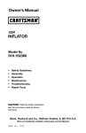
AIR COMPRESSOR
o
Safety
o
Guidelines
Assembmy
o
Operation
o
Maintenance
o
Service
and Adjustments
o
o
Repair
Parts
CALiT|ON:
Read the Safety Guidelines
and All instructions Carefully Before
Operating.
Sears,
Roebuck
and Co., Hoffman
Visit our Craftsman
A10282 R_v.
0 2JlsJ0._
website:
Estates,
mL60179
www, sears,com/craftsman
U.S.A.
WARRANTY ................................................
SPECiFiCATiON
CHART .....................................
SAFETY GUiDELiNES ......................................
2
3
3-8
GLOSSARY ................................................
ACCESSORIES
............................................
DUTY CYCLE ..............................................
ASSEMBLY ...............................................
9
9
9
10
iNSTALLATiON .........................................
OPERATION ...........................................
MAINTENANCE .........................................
SERVICE AND ADJUSTMENTS ............................
10-11
12-14
14-15
15-16
STORAGE ................................................
TROUBLESHOOTING
GUIDE .............................
REPAIR PARTS .........................................
ESPANOL ..............................................
NOTES/NOTAS ............................................
17
18-19
20-23
24-41
42
REPAIR PROTECTION AGREEMENTS .........................
HOW TO ORDER REPAIR PARTS ......................
FULL
ONE YEAR
WARRANTY
AiR
43
back cover
COMPRESSOR
If this CRAFTSMAN Air Compressor fails due to a defect in material or
workmanship within one year from the date of purchase, Sears will at
its option repair or replace it free of charge. Contact your nearest Sears
Service Center (1-800-4-MY-HOMP)
to arrange for repair, or return the Air
Compressor to the place of purchase for replacement.
If this Air Compressor is used for commercial or rental purposes, this warranty
applies for only ninety days from the date of purchase.
This warranty gives you specific legal rights and you may have other rights
which vary from state to state.
Sears, Roebuck
and Co., Dept. 817WA, Noffman
Estates,
IL 60179
ModeB No.
919.152145
Running HP
Bore
Stroke
1
47.625
31.75
Voltage-Single
Phase
120V
Minimum Branch Circuit Requirement
Fuse Type
Air Tank Capacity
Approx. Cut-In
10 amps
Time Delay
4
120
Approx. Cut-out
SCFM @ 40 psig
SCFM @ 90 psig
150
3.7
2.6
Refer to Glossary for abbreviations.
This manual contains information that is important for you to know and
understand. This information relates to protecting YOUR SAFETY and
PREVENTING EQUIPMENT PROBLEMS. To hetp you recognize this
information, we use the symbols below. PIease read the manual and pay
attention to these symbols.
_
situation which, if not avoided,
in death or serious iniury.
i
which, if not avoided, _
or moderate ini_
will result
Indicates a potentially
hazardous situation
which, if not avoided, could
death or serious in'ULUEy.
Indicates a potentially
hazardous situation
result in minor
_Used
without the
safety alert symbol
indicates a potentially hazardous situation
which, if not avoided, may result in
re err dama e.
result in
Some dust created by power sanding, sawing, grinding,
drilling, and other construction
activities contains
chemicals known (to the State of Camifornia) to cause cancer, birth defects
or other reproductive
harm. Some exampme of these chemicals are:
lead from lead-based paints
crystalline silica from bricks and cement and other masonry products
arsenic and chromium from chemicaBly-treated
Bumber
Your risk from these exposures varies, depending on how often you do
this type of work. To reduce your exposure to these chemicals: work in
a wemlventilated area, and work with approved safety equipment, atways
wear MSNA/NIOSN approved, proper_y fitting face mask or respirator when
using such tooms.
When using air tools, basic safety precautions shoumd a_ways be followed
to reduce the risk of of personal injury.
3-ENG
A10282
Gave these
instructions
Improper operation or maintenance of this product could result in serious injury and
property damage. Read and understand all warnings and operation instructions before
using this equipment.
WARNING:
Risk
of explosion
or fire
What Could Happen
_,i
How To Prevent
It
mtis normal for electrical contacts within
the motor and pressure switch to spark,
Always operate the compressor
in a
well ventilated area free of combustible
materiame, gasoline, or somvent vapors.
mfelectrical sparks from compressor
come into contact with flammable
vapors, they may ignite, causing fire or
e×plosion,
if spraying flammable materials, locate
compressor
at least 20 feet away from
spray area. An additional length of hose
may be required.
Store flammable
materials in a secure
location
away from compressor.
Restricting
any of the compressor
ventilation openings will cause serious
overheating and could cause fire.
Never place objects against or on top
of compressor.
Operate compressor
in
an open area at least 12 inches away
from any wan or obstruction
that would
restrict the flow of fresh air to the
ventilation openings.
Operate compressor in a clean, dry well
ventilated area. Do not operate unit
indoors or in any confined area.
Unattended
operation of this product
couM resumt in personal injury or
property damage. To reduce the risk
of fire, do not anew the compressor
to
operate unattended.
Always
product
ABways
moving
position
each
A10282
4-ENG
remain in attendance
with the
when it is operating.
disconnect
eRectrical power by
pressure switch lever to the off
and drain tank daily or after
use,
WARNING:
Risk
of Bursting
Air Tank: The following
conditions could lead to a weakening
in a violent tank e×plosion and could cause property damage
of the tank, and result
or serious injury.
Now To Prevent
What Could Happen
Failure to properly drain condensed
water from tank, causing rust and
thinning of the steel tank.
Modifications
the tank.
or attempted
repairs
Unauthorized
modifications
to the
It
Drain tank daily or after each use. If tank
develops a leak, replace it immediately
with a new tank or replace the entire
compressor
to
Never drill into, weld, or make any
modifications
to the tank or its
attachments.
unRoader valve, safety valve, or any
ether components
which eontrom tank
pressure.
Excessive
vibration
can weaken
air tank and cause rupture
explosion
ATTACHMENTS
the
The tank is designed to withstand specific
operating pressures. Never make
adjustments
or parts substitutions
to
alter the factory set operating
pressures.
or
& ACCESSORIES:
For essential control of air pressure, you
must install a pressure regulator and
pressure gauge to the air outBet (if not
equipped} of your compressor. Follow the
equipment manufacturers recommendation
and never exceed the maximum allowable
Exceeding the pressure rating of air
tools, spray guns, air operated
accessories, tires, and other inflatables
can cause them to explode or fly apart,
and could result in serious injury.
WARNING:
pressure rating of attachments. Never use
compressor
to inflate small low
pressure objects such as children's
toys, footballs, basketballs,
etc.
Risk from
What Coumd Happen
Flying Objects
How To Prevent It
The compressed
air stream can cause
soft tissue damage to exposed skin and
can propel dirt, chips, loose particles,
and small objects at high speed,
resulting in property damage or personal
injury.
Always wear ANSI Z87.1 approved
safety gmasses with side shields when
using the compressor.
Never point any nozzle or sprayer
toward any part of the body or at other
people or animals.
Always turn the compressor
off and
bleed pressure from the air hose and tank
before attempting maintenance, attaching
tools or accessories.
5 - ENG
A10282
WARNING:
Risk of Electticam Shock
Now 3"o Prevent
What CouBd Happen
it
Your air compressor
is powered by
eRectricity, Like any other electrically
powered device, If it is not used
property it may cause eRectric shock.
Never operate the compressor outdoors
when it is raining or in wet conditions.
Repairs attempted by unqualified
personneB can result in serious injury
or death by electrocution.
Any electricam wiring or repairs required
on this product should be performed
by
authorized service center personnel in
accordance with national and local
electrical codes.
Electrical Grounding: Failure to provide
adequate grounding to this product
could result in serious injury or death
from electrocution.
Make certain that the electrical circuit
to which the compressor is connected
provides proper eBectrical grounding,
correct voltage and adequate fuse
protection.
See grounding
Never operate compressor
protective covers removed
instructions.
WARNING:
Risk to Breathing
Now To Prevent It
What Could
The compressed
air directly from your
compressor is not safe for breathing.
The air stream may contain carbon
monoxide, toxic vapors, or solid
particles from the tank. Breathing these
contaminants
can cause serious injury
or death.
Sprayed materials such as paint, paint
solvents, paint remover, insecticides,
weed killers, may contain harmful
vapors and poisons.
A10282
with
or damaged.
Air obtained directly from the compressor
shouM never be used to supply air for
human consumption.
In order to use air
produced by this compressor for
breathing, suitable filters and in-line
safety equipment must be property
installed. In-line filters and safety
equipment used in conjunction with the
compressor must be capabBe of treating
air to aH appBicable local and federam
codes prior to human consumption.
Work in an area with good cross
ventilation.
Read and follow the safety
instructions
provided on the label or
safety data sheets for the materiaBs
you are spraying. Use a NmOSH/MSHA
approved respirator designed for use
with your specific application.
6-ENG
WARNING:
Risk of Burns
What Could Happen
How To Prevent
it
Touching exposed metaB such as the
compressor head or outlet tubes, can
result in serious burns.
Never touch any exposed metal parts
on compressor
during or immediately
after operation. Oompressor will remain
hot for several minutes after operation.
Do not reach around protective shrouds
or attempt maintenance
until unit has
been allowed to cool
m
WARNING:
Risk from Moving
What Could Happen
m
Parts
_
Now To Prevent it
Moving parts such as the pulley,
flywheel, and belt can cause serious
injury if they come into contact with you
or your clothing.
Never operate the compressor
with
guards or covers which are damaged
removed.
Attempting
to operate compressor with
damaged or missing parts or
attempting to repair compressor with
protective shrouds removed can expose
you to moving parts and can result in
serious injury.
Any repairs required on this product
should be performed
by authorized
service center personnel
WARNING:
What Could
or
Risk of Falling
How To Prevent it
Happen
A portable compressor
can fan from
a table, workbench, or roof causing
damage to the compressor
and could
result in serious injury or death to the
operator.
Always operate compressor
ina stabme
secure position to prevent accidental
movement of the unit. Never operate
compressor
on a roof or other elevated
position. Use additionaB air hose to
reach high locations.
7-ENG
A10282
WARNING:
Risk
of Serious
When
(Fire,
What Could
injury or Property
Transporting
Inhalation,
Damage
Risk
of Unsafe
Operation
How To Prevent
Happen
SAVE THESE
it
Always place OOMPRESSOR on a
protective mat when transporting
to
protect against damage to vehicle from
leaks. Remove COMPRESSOR from
vehicle immediately upon arrival at your
destination.
[_
it
Review and understand all instructions
and warnings in this manual.
Become famiRiar with the operation and
controls of the air compressor.
Keep operating area cBear of all persons,
pets, and obstacles.
Keep chiRdren away from the air
compressor at aH times.
Do not operate the product when
fatigued or under the influence of
alcohol or drugs. Stay alert at all times.
Never defeat the safety features of this
product.
Equip area of operation with a fire
extinguisher.
Be not operate machine with missing,
broken, or unauthorized
parts.
Unsafe operation of your air compressor
could lead to serious injury or death to
you or others.
A10282
SurCaces)
How To Prevent
OiR can leak or spill and could result in
fire or breathing hazard; serious injury or
death can result, oil leaks will damage
carpet, paint or other surfaces in vehicles
or trailers.
What Could
to Vehicle
Happen
WARNING:
Damage
Compressor
mNSTRUCTmONS
8-ENG
Become familiar with these terms
before operating the unit.
CFM: Cubic feet per minute,
SCFM: Standard cubic feet per
minute; a unit of measure of air
delivery.
PSIG: Pounds per square inch
gauge; a unit of measure of pressure,
Code Certification:
Products that
bear one or more of the following
marks: UL, CUL, ETL, CETL, have
been evaluated by OSHA certified
independent safety laboratories and
meet the applicable Underwriters
Laboratories Standards for Safety.
Cut-In Pressure: While the motor
When the tank pressure drops to a
certain Iow level the motor wilI restart
automatically.
The low pressure
at which the motor automatically
restarts is called "cut-in" pressure.
Cut-Out Pressure: When an air
compressor is turned on and begins
to run, air pressure in the air tank
begins to build. It builds to a certain
high pressure before the motor
automatically shuts off, protecting
your air tank from pressure higher
than its capacity. The high pressure
at which the motor shuts off is called
"cut-out" pressure.
Branch Circuit: Circuit carrying
electricity from electrical panel to
outlet.
is off, air tank pressure drops as
you continue to use your accessory.
This unit is capable of powering the following accessories. The accessories are
available through the current Power and Hand Tool Catalog or full-line Sears
stores.
Air Pressure Regulators
Oil Fog Lubricators
Air Hose:l/4", 3/8" OR 1/2" LD. in
various lengths
Accessories
In Line Filter
Tire Air Chuck
® Quick Connector
(various sizes)
Sets
Refer to the selection chart located
on the unit to select the tools this unit
is capable of powering.
This air compressor pump is
capable of running continuously.
However, to prolong the life of your
air compressor, it is recommended
that a 50%-75% average
cycle be maintained; that
compressor pump should
more than 30-45 minutes
hour.
9-ENG
duty
is, the air
not run
in any given
A10282
iiiiiii
....
1.
Remove unit from carton and discard all packaging.
HOW TO SET UP YOUR UNmT
Location
®
of the Air Compressor
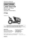
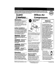
2.
Make sure the outlet being used
has the same configuration as the
grounded plug. DO NOT USE AN
ADAPTER. See illustration.
3.
inspect the plug and cord before
each use. Do not use if there are
signs of damage.
Locate the air compressor in a
clean, dry and well ventilated
area.
*
The air compressor should be
located at least 12" away from
the wall or other obstructions that
will interfere with the flow of air=
®
The air compressor pump and
shroud are designed to allow for
proper cooling. The ventilation
openings on the compressor are
necessary to maintain proper
operating temperature. Do not
place rags or other containers on
or near these openings.
GROUNDING
4.
INSTRUCTIONS
event of a short circuit, grounding
reduces the risk of shock by
providing an escape wire for
the e_ectric current. This air
compressor
must be propermy
grounded,
The portable air compressor is
equipped with a cord having a
grounding wire with an appropriate
grounding plug (see following
illustrations).
1. The cord set and plug with this
unit contains a grounding pin.
This plug MUST be used with a
grounded outlet.
IMPORTANT: The outlet being used
must be installed and grounded in
accordance with all local codes and
ordinances.
A10282
Plug
if these grounding instructions
are not completely understood,
or if in doubt as to whether the
compressor is properly grounded,
have the installation checked by
a qualified electrician.
Risk of
EmectricaB Shock,
IMPROPER GROUNDING CAN
RESULT IN ELECTRICAL SHOCK,
Do not modify the pmug provided, If
it does not fit the avaimabmeouttet, a
correct outmet should be installed by
a quaBified emectrician,
Repairs to the cord set or pBug
MUST be made by a quaBified
emectrician,
10 - ENG
Extension
Cords
Voltage
Using extension cords is not
recommended. The use of extension
cords wiII cause voltage to drop
resulting in power loss to the motor
and overheating.
Instead of using an extension cord,
increase the working reach of the
air hose by attaching another length
of hose to its end. Attach additional
lengths of hose as needed.
and Circuit
Protection
Refer to the specification chart for the
voltage and minimum branch circuit
requirements.
_Risk
of Opertion,
Certain air
compressors
can be operated on
a 15 amp circuit if the following
conditions are met.
1.
Voltage suppIy to circuit must
comply with the National
Electrical Code.
a 3-wire extension cord that has
a 3-blade grounding plug, and a
3-slot receptacle that will accept
the plug on the product
2.
Circuit is not used to supply any
other electdca! needs.
3.
Extension cords compiy with
specifications.
e
in good condition
4.
o
no longer than 50 feet
e
14 gauge (AWG) or larger. (Wire
size increases as gauge number
decreases. 12 AWG and 10 AVVG
may also be used. DO NOT USE
16 OR 18 AWG.)
Circuit is equipped with a 15 amp
circuit breaker or 15 amp time
deIay fuse. NOTE: If compressor
is connected to a circuit
If an extension cord must be used, be
sure it is:
protected by fuses, use only time
delay fuses. Time delay fuses
should be marked "D" in Canada
and "T" in the US.
If any of the above conditions
cannot be met, or if operation of
the compressor repeatedly causes
interruption of the power, it may be
necessary to operate it from a 20 amp
circuit. It is not necessary to change
the cord set.
11-ENG
A10282
Know Your Air Compressor
READ THiS OWNER'S MANUAL AND SAFETY RULES BEFORE OPERATING
YOUR UNIT. Compare the iIIustrations with your unit to familiarize yourself with
the !ocation of various controls and adjustments. Save this manual for future
reference.
Safety VaRve
Description
of Operation
Become familiar with these controls
before operating the unit.
On(l)/Off(O} Switch: Place this switch
in the ON (I) position to provide
automatic power to the pressure
switch and OFF (O) to remove power
at the end of each use.
Pressure Switch (not shown}: The
pressure switch automatically starts
the motor when the air tank pressure
drops below the factory set "cut-in"
pressure, it stops the motor when the
air tank pressure reaches the factory
set "cut-out" pressure.
Safety Vamve: if the pressure switch
does not shut off the air compressor
at its "cut-out" pressure setting, the
safety valve will protect against high
pressure by "popping out" at its
factory set pressure (slightly higher
than the pressure switch "cut-out"
setting}.
Tank Pressure Gauge: The tank
pressure gauge indicates the reserve
air pressure in the tank.
A10282
OutNet Pressure Gauge: The outlet
pressure gauge indicates the air
pressure available at the outlet side
of the regulator. This pressure is
controlled by the regulator and is
always less than or equal to the tank
pressure.
Regumator: Controls the air
pressure shown on the outlet
pressure gauge. Turn regulator knob
clockwise to increase pressure
and counterclockwise
to decrease
pressure.
Cooling System (not shown}: This
compressor contains an advanced
design cooling system. At the heart of
this cooling system is an engineered
fan. it is perfectly normal for this fan
to blow air through the vent holes
in large amounts. You know that the
cooling system is working when air is
being expelled.
Air Compressor
Pump (not shown}:
Compresses air into the air tank.
Working air is not available until the
compressor has raised the air tank
pressure above that required at the air
outlet.
12 - ENG
Drain Valve:
I-The drain valve /
is located at
[
the base of the
artankand
s
used to drain
condensation at the end of each use.
Oheck Valve: When the air
compressor is operating, the check
vane is "open", allowing compressed
air to enter the air tank. When the
air compressor reaches "cut-out"
pressure, the check valve "closes",
allowing air pressure to remain inside
the air tank.
Valve
2.
Plug the power cord into the
correct branch circuit receptacle.
(Refer to Voltage and Circuit
Protection paragraph in the
Installation section of this
manual.)
3.
Open the drain valve (counterclockwise) fully to permit air to
escape and prevent air pressure
build up in the air tank during the
break-in period.
4.
Move the On/Off switch to ON (I)
position. The compressor will start.
5.
Run the compressor for 15
minutes. Make sure the drain
vaJve is open and there is minimal
air pressure build-up in tank.
6.
After 15 minutes, close the drain
valve by turning clockwise. The
air receiver wiJI fill to "cut-out"
pressure and the motor wiII stop.
How to Use Your Unit
The compressor
Now to Stop:
Before
1.
1.
Set the On/Off switch
2.
Pull the regulator knob out and
turn counterclockwise
to set the
outlet pressure to zero.
3.
Attach hose and accessories.
Set the On/Off switch to OFF (0).
Before
Starting
Break=in Procedure
_Risk
of Unsafe
Operation.
Serious damage may result if the
following breakdn instructions are
not closely followed°
This procedure is required before the
air compressor is put into service and
when the check valve or a complete
compressor pump has been replaced.
1.
Js now ready for use.
Each Start=Up:
to OFF (O).
NOTE: The hose or accessory will
require a quick connect plug if the
air outlet is equipped with a quick
connect socket.
Make sure the On/Off switch is in
the OFF (O) position.
13-ENG
A10282
How to Start:
pressure
causesa hazardous
risk of bursting, Check the
manufacturer's
maximum pressure
rating for air too{s and accessories,
The regumator outmet pressure
must never exceed the maximum
pressure rating,
1,
Set the QWOff switch to ON O)
and allow tank pressure to build.
Motor will stop when tank pressure
reaches "cut-out" pressure.
2.
Pull the regulator knob out
and turn clockwise to increase
pressure. When the desired
pressure is reached push knob in
to lock in place.
The compressor
iiiiii_
....
is ready for use.
:
iiiiil
....
Customer Responsibilities
Before
each
use
Daily
or after
each
use
3heck Safety Valve
O
O
:>rainTank
To Check
power is on. When performing
maintenance, you may be exposed
to voltage sources, compressed
air,
or moving parts. PersonaB injuries
can occur. Before performing any
maintenance
or repair, disconnect
power source from the compressor
and bmeed off aH air pressure.
NOTE: See "Operation" section for
the location of controls.
A10282
Safety
VaJve
propermy, over-pressurization
may
occur, causing air tank rupture or
an expmosion.
1. Before starting compressor, pull
the ring on the safety valve to
make sure that the safety valve
operates freely. If the valve
is stuck or does not operate
smoothly, it must be replaced
with the same type of valve.
14 - ENG
To Drain
Tank
_
1.
Set the On/Off switch to OFF (O).
2.
Pull the regulator knob out and
turn counterclockwise
to set the
outlet pressure to zero.
3.
Remove the air tool or accessory.
4.
Pull ring on safety valve a!lowing
air to bleed from the tank until
tank pressure is approximately 20
psi. Release safety valve ring.
5.
Drain water from air tank by
opening drain valve on bottom of
tank.
Water will
condense in the
air tank, If not drained, water wHm
corrode and weaken the air tank
causing a risk of air tank rupture,
6.
After the water has been drained,
close the drain valve. The air
compressor can now be stored.
NOTE: If drain valve is plugged,
release all air pressure. The valve
can then be removed, cleaned, the
reinstalled.
ALL MAINTENANCE AND REPAIR OPERATIONS NOT LISTED MUST BE
PERFORMED BY TRAINED SERVICE TECHNICIAN.
_Risk
of Unsafe Operation, Unit cycmee automatically
when
power is on, When servicing, you may be exposed to
vomtage sources, compressed
air, or moving parts, Before servicing unit
unplug or disconnect electricam supply to the air compressor, bracedtank of
pressure, and allow the air compressor to cool
To Replace
or Clean
Check
Valve
1.
Release all air pressure from air
tank. See "To Drain Tank" in the
Maintenance section.
Hose Clamp
2.
Unplug unit.
3.
Remove the hose by removing
the hose clamp. NOTE: The hose
clamp is not reusable. You must
purchase a new hose clamp, see
the Parts List Manual or purchase
a standard hose clamp at a local
hardware store.
15-ENG
Cheek
Valve
Unscrew the check valve (turn
counter-clockwise) using a
socket wrench.
A10282
Make sure the valve disc moves
freely inside the check valve
and the spring holds the disc in
the upper, closed position. The
check valve may be cleaned
with a soivent, such as paint and
varnish remover:
6.
Apply sealant to the check valve
threads. Reinstall the check valve
(turn clockwise).
7.
Replace hose and new hose
clamp.
8.
Perform the Break-in Procedure.
See "Break-in Procedure" in the
Operation section.
5.
Remove pump mounting screws
securing pump (one on each
side).
6.
Carefuily slide pump from
brackets and out of the way.
7.
Using an adjustable wrench or
5/8" wrench remove the regulator
manifold.
To Replace Regulator
1. Release all air pressure from air
tank. See "To Drain Tank" in the
Maintenance section.
2.
Unplug unit.
3.
Using an adjustable wrench or
specified wrench remove the
gauges (7/16" wrench), quick
connect (13/16" wrench), and
safety valve (9/16" wrench) from
the regulator manifold.
Pump shown
moved out of
the way
Regulator
d
Apply pipe sealant to new
regulator manifold and assemble,
tighten with wrench.
9.
Reapply pipe sealant to gauges,
quick connect, and safety valve.
10. Reassemble all components in
reverse order of remova!. Make
sure to orient gauges to read
correctly and use wrenches to
tighten all components.
ManifoBd
4.
8.
Remove the hose by removing
the hose clamp. NOTE: The hose
clamp is not reusable. You must
purchase a new hose clamp, see
the Parts List Manual or purchase
a standard hose clamp at a local
hardware store.
Hose Clamp
Regulator
Manifold
A10282
16
ENG
Risk of Bursting,
Water will
condense in the air tank, if not
drained, water will corrode and
weaken the air tank causing a risk
of a{r tank rupture,
Before you store the air compressor,
make sure you do the following:
1.
Review the "Maintenance"
section on the preceding
pages and perform scheduled
maintenance as necessary.
2.
Set the On/Off switch to OFF (O)
and unplug unit.
3.
Turn the regulator
counterclockwise
and set the
outlet pressure to zero.
4.
Remove the air tool or accessory.
5.
Pull ring on safety valve allowing
air to bleed from the tank until
tank pressure is approximately 20
psi. Release safety valve ring.
6.
Drain water from air tank by
opening drain valve on bottom of
tank.
7.
After the water has been drained,
close drain valve by turning
clockwise.
NOTE: If drain valve is plugged,
release all air pressure. The valve
can then be removed, cleaned, then
reinsta!Ied.
8.
Protect the electrical cord and
air hose from damage (such as
being stepped on or run over).
Wind them Ioosely around the
compressor handle.
9.
Store the air compressor
clean and dry location.
17-ENG
in a
A10282
_
Performing repairs may expose vomtage sources, moving
parts or compressed
air sources. Personal injury may
occur. Prior to attempting any repa{rs, unplug the air compressor
and
bleed off aH air tank air pressure.
PROBLEM
CAUSE
CORRECTION
Pressure switch does
not shut off motor when
compressor reaches "cutout" pressure.
Move On/Auto/Off lever to
the "Off" position, if the
outfit does not shut off
contact a Trained Service
Technician.
Pressure switch "cut-out"
too high.
Contact a Trained Service
Technician.
Air leaks at
fittings.
Tube fittings are not tight
enough.
Tighten fittings where air
can be heard escaping.
Check fittings with soapy
water solution. Do Not
Overtighten,
Air leaks in air
tank or at air
tank welds.
Defective air tank.
Air tank must be replaced.
Do not repair the leak.
Excessive
pressure
tank
- safety
valve pops
Air leaks
between
off.
Leaking
wemd or otherwise modify
air tank or it will weaken,
The tank can rupture or
expmode,
Contact a Trained Service
Technician.
seal.
head
and valve plate.
Air leak from
safety valve.
Possible defect in safety
valve.
Operate safety valve
manually by pulling on ring.
if valve still leaks, it should
be replaced.
Knocking
Possible defect in safety
valve.
Operate safety valve
manually by pulling on ring.
if valve stiII leaks, it should
be replaced.
A10282
Noise.
18 - ENG
PROBLEM
Pressure reading
on the regulated
pressure gauge
drops when an
accessory is
used.
CAUSE
CORRECTION
It is normal for "some"
pressure drop to occur.
If there is an excessive
amount of pressure drop
when the accessory is used,
adjust the regulator following
the instructions in the
"Description of Operation"
paragraph in the "Operation
Section.
NOTE: Adjust the regulated
pressure under flow
conditions (while accessory is
bein, used.
Prolonged excessive use of
air.
Decrease amount of air
usage.
Compressor is not large
enough for air requirement.
Check the accessory
air requirement. If it is
higher than the SCFM or
pressuresuppliedby your
air compressor, you need a
larger compressor.
Hole in hose.
Check and replace if
required.
Check valve restricted.
Remove and clean, or
replace.
Air leaks.
Tighten fittings.
Regulator knob
has continuous
air leak.
Damaged regulator
Replace
Regulator will
not shut off air
outlet.
Damaged regulator
Replace
Compressor is
not supplying
enough air
to operate
accessories.
19-ENG
A10282
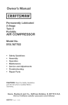
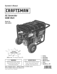
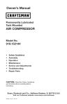
Air Compressor
Modem Number
9i9ot52145
24
\
iO
8
\'37
Torqueto
i0-20 in.qbs.
A10282
20-ENG
Air Compressor
Key
No.
1
2
3
5
7
8
9
10
11
17
18
22
24
37
+
Model
Number
919o152145
Part Number
Z-D24671
SST-108
91895680
A07521
........
D20114
Z-D21929
Z-D27212
D20675
CAC-1254
D27022
CAC-1206-1
SSF-621
A06891
Description
Air Receiver
Recess Rubber Bumper
Screw (3)
Regulator
Pump Assembly
Safety Valve
Gauge 2"
Gauge 2"
Quick Connect 1/4 NPT
Pump Isolator (4)
Check Valve
Hose CJamp
Screw (2)
Drain Valve
Not illustrated
LA-3092-1
LA-2876
LA-3108
LA-3270
A! 0466
D21921
Label, Drain Tank Eng/Spa
Cord Assembly
Label, Hot Surface
Label, Warning Eng/Spa
Label, Sears Performance
Label, Star Rating #3
+ order individual parts, see pump diagram
21-ENG
A10282
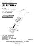
>
o
O
O
B
"o
@
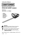
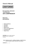
Torqueto
30-45in.-lbs
13
8
o
z
20
B
....
1
Torqueto be handtigh t
to 10 in.qbs,max.
/
7
6
/
/,
/
N
/
15
Torqueto
49-55in.qbs
FR
z
©
4_
{gl
24_
18
\
\18
'5
16
Air Compressor
KEY
NO.
1
2
3
4
5
6
7
8
9
9-8
9-9
9-10
9-11
9-12
9-13
10
13
14
15
16
17
18
19
20
21
22
23
24
25
26
27
Model
Number
919°152145
PART HUMBER
A10099
A10100
D25877
CAC-1212
D22253
CAC-1199
Z-A08548
÷
÷
DESCRIPTION
Shroud (right)
Shroud (left)
Head
Tube Seal
Outlet Tube
Head Gasket
Valve Plate Assembly
Gasket
Sub Pump Assembly
Rod Assembly
Pre-Formed Compression Ring
Connecting Rod Cap
Screw #10-24
Screw, 3/8-16 UNC Socket Head
Cylinder Sleeve
Timing Belt
Screw, #8-32
Pump Isolator (5)
Washer Screws 10-24 x 7/8 (4)
Rocker Switch
Motor Cord
÷
Z-A04615
>
+
+
x
+>
x
x
e
x
**
e
e
e
x
>
+
÷
e
D21127
SSF-3147
AC-0815
SUDL-9-1
D25731
SSF-995
D28870
A04770
CAC-1206-1
H-7051
SSF-3156
Hose Clamp
Hose 1/4 ID x 10" Length
Screw, 10-9 x 1/2 Plastite (5)
Motor Brush Replacement
Pressure Switch
A05802
A00470
A05239
A10162
A10109
A10111
Support Handle
Bracket
Air Hose .25 ID
Jumper Wire 18GA 6.6
Jumper Wire 18GA 9.2
Hot Hlustrated
LA-3270
A10282
KK-4929
KK-4964
D30324
D30139
A10580
Label, Warning Eng/Span
Owners Manual
Fastener Kit
Connecting Rod Kit
Ring Kit
Gasket and Seal Kit
Pressure Switch Kit
** REPLACEMENT BRUSHES FOR MOTOR
Motor number and vendor is stamped on motor stack. Both must be identified
before ordering replacement brush.
Motor
M0-9088
D23494
D27098
D27098
D27219
Vendor
Northland
GS Electric
GS Electric
ECM (Gold
GS Electric
(Ametek)
(Ametek)
Tuning)
(Ametek)
23-ENG
Brush Set
Z-D20041
Z-D23825
Z-D23825
Z-D27196
Z-D23825
A10282
GARANTiA ...........................................................
CUADRO
DE ESPECIFICACIONES
24
.......................................
DEFINmCIONES DE NORMAS DE SEGURIDAD
DE SEGURmDAD ...................................................
25
251MPORTANTES
mNSTRUCCIONES
25-30
GLOSARIO ...........................................................
30
ACCESORIO$
30
.......................................................
CICLO DE SERVmCIO ..................................................
ENSAMBLAGE
30
........................................................
32
mNSTALACI6N .....................................................
32-33
OPERACION
34-36
......................................................
MANTENIMIENTO
..................................................
SERVICIOS Y REGULACIONES
ALMAOENAJE
CONTRATO$
37-38
........................................................
GUIA DE DIAGNOSTICO
NOTES!NOTAS
36-37
.......................................
DE PROBLEMAS
39
.............................
40-41
.......................................................
DE PROTECCION
LIST,& DE PARTES
42
PARA REPARACIONES
.....................
.................................................
COMO SOLmCITAR PIEZAS PARA REPARACION
43
20-23
....................
contratapa
iiii .
GARANTiA
,....
TOTAL DE UN Al_O DEL OOIVIPRE$OR DE AIRE
Si este compresor de aire Craftsman fa!lase debido a defectos de materiales
o de fabricaci6n dentro del aSo de su fecha de compra, Sears, a su opci6n,
Io reparara o reempiazara sin costo alguno. Comuniquese con el Centre de
Servicio Sears mas cercano (1-800-4-MY-HOME) para coordinar su reparaci6n, o devuelva e! compresor de aire al lugar donde Io compr6 para que Io
cambien.
Si este compresor de aire se usase con fines comemiaies o para alquibr, esta
garantia se aplica s6io durante los primeros noventa dias a partir de su fecha
de compra.
Esta garantia ie otorga derechos especfficos y usted podria tenet otros derechos que varian de un estado a otto.
Sears, Roebuck
A10282
and Co., Dept. 817WA, Hoffman
24 - SP
Estates,
IL 60179
Modelo
N°
919o152145
1HP
Potencia de trabajo
DiAmetro interior
Carrera
1,875 (47,625mm)
1,250 (31,75mm)
120V
10A
Voltaje-corriente manofAsica
Circuito minima requerido
Tipo de fusibleAccian
retardada
Capacidad de aire en el tanque
Presian de carte de entrada
Presian de carte de salida
4 Galones (15,1 litros)
120 psig
150 psig
3,7 Calibre de libras
par pulgada cuadrada
2,6 Calibre de libras
par pulgada cuadrada
SCFM a 40 psig
SCFM a 90 psig
Refiarase al glosario para descifrar las abreviaturas.
Este manual contiene informacian que es importante que usted conozca y comprenda.
Esta informacian se relaciona con la proteccian de SU SEGURBDADy LA PREVENCmON
DE PROBLEMAS A SU EQUmPO.Para ayudarlo a reconocer esta informacian, usamos
los dmbolos indicados m_s abajo. Sfrvase leer el manual y prestar atenci6n a estas
seooiones.
_
Indica una situacian
de riesgo inminente,
que si no se evita, causar_ la muerte o
lesiones serias.
_
Indica una situacian potencialmente riesgosa, que si no se evita,
podria causar la muerte o lesiones
serias.
Usado sin el dmbolo
de seguridad de
alerta indica una situacian potencialmente
riesgosa la que, si no se evita, podr[a
caasar da_os en Ra_iedad.
Indica una situacian
potencialmente
peligrosa, que si no se evita, puede
causar lesiones menores o moderadas.
AIgunos tipos de polvo creados par herramientas motodzadas de lijado, aserrado, amolado/esmerilado,
perforado u otras actividades de la construccian, contienen materiales qdmicos conocidos (en el Estado de California) coma causantes de cancer, defectos de
nacimiento u otras lesiones del aparato reproductivo. AIgunos ejemplos de estos productos qdmicos son:
,,
El p_omo contenido
.
Si_ice cristalizado
en algunas pinturas con base de p_omo.
,,
Ars&nico y cromo provenientes
proveniente
de los ladri_los, e_ cemento y otros pr_ductos
del tratamiento
quimico
de a_bafiileria.
dado a la madera.
Su riesgo a esas exposiciones
vafiara dependiendo de la frecuencia con _aque usted realice
diferentes tipos de trabajo= Para r÷ducir su exposician a _aaccian de dichos agentes quimicos:
Trabaje en zonas bien venti_adas y hagalo con equipo de seguridad aprobado, use siempre proteccian
facial o respirador aprobado per MSHA / NHOSHcuando opere esas herramientas,
AI utilizar herramientas neumaticas tambien deben tomarse
de reducir la posibHidad de riesgo de lesiones personales.
25 - SP
precauciones
basicas de seguridad,
a fin
A10282
GUARDE
ESTAS |NSTRUCCiONES
La operaci6n o el mantenimiento
inadecuados
de este producto
podrfan ocasionar
lesiones serias y da_os ala propiedad.
Lea y comprenda
todas las advertencias
e
instrucciones
de funcionamiento
antes de utilizar este equipo.
ADVERTENCIA:
8Qu6
Riesgo
puede
de
Explosi6n
o mncendio
occurrir?
_
806mo
[
prevenirlo?
Es normal que Uos eontactos
eU_ctficos del
motor y deI interrupter
de presi6n emitan
eHspas.
Siempre opere eUcempreser
en un sector
bien venti_ado y sin matedaUes combustibles,
gasoUina e emanaeiones
de eoUventes.
Si las chispae electdcas provenientes de_
compresor tomaran eentacto con
emanacionee
de materiaUes infiamables,
ellos podrian ardor originando
ineendio
e×plosi6rL
En un area de rociado de materiales inflamables,
ubique el compresor
pot Io menos a 6,1m (20
pies) de distancia den area de rociade. Podda
requedrse una extensi6n de la manguera.
o
AUmacene nee materiaUes inflamables
en nee
ubicaci6n segura, alejados del compreeor.
Restringir
cualquiera de las aberturas de
ventHaci6e causar_ un eerie recalentamiente
y podria prodncir
un incendie.
James coUoque objetos apoyados o sobre eU
eompresor. Opere el eompresor
en uu'_sector
abierto, aiejado pot Ue menos 30 cm (12") de
cualquier pared u obstruccidn que r÷stdnja el
flujo de aire fresco alas aberturas de venti_aci6m
Opere el compresor en un sector limpio, seco, y
bien venti_ado= No opere la unidad en espacios
eerrados o euaUquier _rea confinada,
bejar
Mant_ngase
siempre alerta carla vez qne e{
producto este funcionando.
Siempre descenecte
el suministro
el_ctrico
meviendo la paUanca conmutadora
de presi6e a Uaposici6n de apagado (off y drene el
tanque diariamente
o despn_s de carla use.
desatenida
esta
en funcioeamiento
persoeaUes
reducir
A10282
o daSos
eU riesgo
e{ eompresor
unidad
puede
a Ua propiedad,
de hcendio,
epere
mieetras
causar
desatendide.
esta
Ueeiones
Pare
no permita
qne
26 = SP
i_
ADVERTENCIA:
e]
!
Riesgo de E×plosi6n
Tanque de aire: las siguientes condiciones podrfan, causar el debilitamiento
causar su explosi6n violenta, da_ios a la propiedad o lesiones serias,
_,Qu6
puede
occurrir?
_C6mo
EUd_enaje inadecuado deU agua condensada
en eUtanque le cauea 6×ido que reduce el
eepeeor deU tanque de acero.
Modificaciones
o intente
de reparacionee
no autorizadae
de descarga,
otto
v_lvuUa
componente
al
presi6n
el tanque
controle
e×cesiva
de
AD/TAMENTOS
aire
puede
y causar
sse_de,
o sus
o efectQe
modificaci6n
accseorios.
o cuaiquier
El tanque esta dise_ado para r_sistir presiones
operativas espec[ficas. Jam_s efectue ajuetes
suetituya pastes que aUteren las regulacionee
de presi6n
originalee de f_brica.
debHitar
su
ruptura
o
Y ACCESORJOS
Ua preei6n
herramientae
aeeeserise
explosi6n
ooasionar
aU tanque
la
exploei6n.
y otrse
pedore,
aUguna
deU tanque.
La vibraci6n
E×ceder
Jamas
a Ua vaIvula
de seguridad
que
prevenirlo?
Drene el tanque diariarnente
o despu_e de
cada use. Si el tanque genera una perdida,
reempl_celo inmediatamente
con un nuevo
tanque o r_emp[ace e_compresor completo.
tanque.
Modificaciones
del tanque, y
eepecificada
neum_ticas,
activadse
pot
objetos
inflables,
para
Para un control precise de la presion, debe usted
inetalar an reguUador y un medidor de preei6n
a la salida del aire de su compresor (Si no
estuviese equipado) Siga las recomendacioses de
_os fabdcantes de su equipo y jamas exceda los
valores maximse de presi6n permitidse pars los
acceserise. Jam_s use e8 cempresor para briar
objetoe que requieren poca o baja preei6n,
tales come juguetee para Uoe ni_os, peUotas de
ft_tboU, pelotae de bgequet, etc.
Uae
pistolas
rociadoras,
age, I_antas seumaticae
puede
cauear
o que salgan
disparados,
lesiones
serias.
o
eu
pudiendo
e]
ADVERTENOIA:
Riesgo
de Objetos
Arrojados
pot el Aire
_,Qu6 puede occurrir?
_,C6mo preveniHo?
El chorro de aire comprimido
puede causar
leeiones a _oe tejidos biandos de la pie_
expuesta y puede propu_sar suciedad, astillas,
part_cu_as sue_tas y pequedos ebjetos a affa
ve_ocidad, ocasionando da[tse a la propiedad o
Iseionse pereonales.
A] uti{izar
anteojos
e_ compresor,
de seguridad
aprobados
Jamas
segun
apunte
haeia
partes
animalee.
use
con
_a norma
boquiHa
de_ cuerpo,
siempre
protecci6n
Z87.1
o pu_verizader
a otrae
_atera_
de ANSL
a_guno
personas
o
Siempre apague el compresor
y purgue la
preei6n de la manguera de aire y del tanque,
antes de intentar el mantenimiento, el acople
herran'ge[_tae o acceserios.
27-SP
de
A10282
ADVERTENCIA:
Riesgo
deDescarga
ER_ctrica
_
sQu_puede
occurrir?
Sucompresor
desireesta
accionado
per
ebctricidad.
Come
cualquier
ottodispositivo
electrico
accionado
el_ctricamente,
sinoseIo
utiliza
adecaadamente,
podria
causarle
una
desearga
eU_ctriea.
_,C6mo
prevenirlo?
Jam#_s
opere
elcompresor
alaintemperie
cuando
esta
Hoviendo
oencondiciones
de
humedad.
Nunca
opere
eU
eompresor
sinsus
cubiertae
oeiestuviesen
daSadas,
Lae
Cualquier conexi6n el_ctrica o reparaci6n
reqaerida per esta anidad debe haceHa eU
personal de los servicentros
autorizados
de
acuerdo a los cddigos e_ctricos nacionales y
bcales.
reparacionee
intentadas
calificade
podrian
la muerte
per
ocaeionar
per
personaU
Ueeiones
no
cerise
o
electrocuei6n,
CONEX_ON A TIERRA: Dejar de proveer ana
cene×i6n adecaada a tierra a esta anidad
podria ocasionar lesiones serias o Uarosette
per eUeetrocuci6n,
Vea las instrucciones para la
puesta a tierra.
ADVERTENOIA:
Asegurese
qae el eireuito eleetrico
a_cual est#_
conectado el compresor_ tiene conexi6n apropiada a tierra, el voltaje correcto y proteeeiSn
adecuada per fusiMes,
Riesgo de Inhalaci6n
#,Qu6 puede occurrir?
$C6mo
prevenirlo?
El aire comprimido
proveniente del compresor
no es sane pars respirar.
El cherro de aire
paede contener mon6xido de carbono o
particaUas s6lidas deU tanqae, La inhaUaci6n
de esos contaminantes
puede Hegar a caasar
lesiones serias o Uarosette.
El sire del compresor jamas debe usarse
directamente pars consume humane; a menos
que primero se le instale filtros adecuados y
un equipo de seguridad en linea, capaces de
procesar e_air÷ de acuerdo a todos los codigos
_ocales y federabs.
El rociado de materialee tales come pintura,
solventes, removedores de pintura, insecticidas,
herbicidas,
produce
emanaoiones
nocivae y
venenosas,
Trabaje en un 9tea con buena ventilaci6n
cruzada. Lea y siga las instrucciones
de
segaridad
provistas en el rgtulo o en los dates
de _as hojas de seguridad de1 material qae esta
paiverizando,
Use el respirador
aprobado per
NIOSH/MSHA
designado para utilizarse con su
aplicaci6n especifica.
A10282
28-SP
ADVERTENCIA:
Riesgo
de Quemaduras
8Qu_ puede occurrir?
8C6rno
preveniHo?
Jam_s toque partes de metal expuestas
en eU
compresor
durante o inmediatamente
despues
de la operaci6n. EJ cempresor
permanecer_
caliente
pot vados minutos luego de la
operaci6n.
Tecar eUmetaU expuesto tal como el cabezal
de! compresor o los tubos de salida del escape,
puede ecasionarle
quemaduras
serias.
No buHe Uas cubiertae
protectoras o intente eU
mantenimiento
hasta que la unidad se enfde.
ADVERTENCIA:
8Qu_
puede
Riesgo
de Partes
M6viles
occurrir?
_
8C6rno
L_
J
preveniHo?
Partes movib[es tales como _a polea, el vo_ante
y la cornea podr_an set Uacausa de lesionee
serias usted ci o su ropa entran en contacto con
elias.
Nunca epere
si estuviesen
Intentar
dafiadas
cubiertas
a piezas
Uesiooes
Cualquier reparaci6n requerida pot esta unidad
debe hacerla eUpersonaU de uo servicentro
autorizado,
operar eU compresor
con piezae
o faUtantes, o reparaHo sin sue
puestas, puede exponeHo austed
eo movimiento
que le ocaciou'_en
serias.
ADVERTENCIA:
8Qu6
puede
Riesgo
e8 compresor
dafiadas.
de Ca_da
806mo
occurrir?
Un compr÷sor portatil puede caerse de la
mesa, el banco de trabajo o del techo pudiendo
dafiarse y causar lesienes serias o la muerte
deU eperader.
sin sus cubiertas
prevenirmo?
Siempre opere eUcompreser
en una posici6n
estabUe y segura a fin de pr_venir el movimiento
accidenta_ de la unidad. Jam_s opere eU
compresor
sobre un techo u otra poeici6n
e[evada. UtHice mangueras adicionaUes de
aire para aUcanzar posiciones
altos.
29-
SP
A10282
e
ADVERTENCIA: Riesgo de Lesiones Serias o DaSos a la Propiedad
Transportar el ¢ornpresor
(Fuego,
&Qu_
hhaUaci6n,
puede
daSo a Uasuperficie
ADVERTENCIA:
_Qu_
puede
de veh_cuUos}
occurrir?
_,C6mo
EUaceite puede derramarse
generando an desgo de incendio o inhalacion que puede causar
lesiones serias o muerte. E_derrame de aceite
daria a_fombras, pinturas u otras superficies de
vehiculos o remolques,
Riesgo
de Operaci6n
prevenirmo?
Deposite el compresor
sobre uea affombrHla
protectora
euaedo Uotransporte
a fin de
proteger e_ contra los goteos. Retire el compresor de_ vehiculo inmediatamente
despues de
su arribo al destino.
Insegura
occurrir?
_k
_,C6mo
La operacion
insegura de su compresor de aire
podr_a ocasionarUe Uesiones serias o la muerte
a usted u otros,
al
i
preveniHo?
Revise y comprenda todas las instrucciones
advertencias
contenidas en este manual
FamiHaricese con los m_todos
eontroU de! compresor de aire.
Mantenga
personas,
y
de operaci6n
libre la zona de operaciones de
animales domesticos y obstaculos.
Mantenga aUejados a los niSos del compresor
de aire en rode momento,
No opere eUprodueto euando se encuentre
fatigado o bajo Uainfluencia de aUcohol o
drogas, Est_ alerta en todo mornento,
Jam_s aUtere los elernentos
este producto.
de seguridad
Equipe la zona de operaciones
e×tinguidor
de fuego.
con un
No opere Uamaquina si _sta tiene partes
faltantes, rotas o no aatorizadas,
CONSERVAR
A10282
ESTAS mNSTRUCCmONES
30-SP
de
y
Familiarfcese con los siguientes t6rminos,
antes de operar la unidad:
CFM: (Cubic feet per minute) Pies cObicos
per minuto=
SCFM: (Stardard cubic feet per minute)
Pies c0bicos est_ndar por minuto; una
unidad de medida que permite medir la
cantidad de entrega de aire=
PSIG: (Pound per square inch) Libras per
pulgada cuadrada=
ASME: American Society of Mechanical
Engineers (Sociedad Americana
de Ingenieros Mec_nicos); hecho
probado inspeccionado y registrado en
cumplimiento de los est_ndares de la
Presi6n minima de eorte: Cuando
el motor est& apagado, la presi6n del
tanque de aire baja a medida que usted
contin0a usando su accesorio= Cuando
la presi6n del tanque baja al valor fijado
en fAbrica come punto bajo, el motor
volverA a arrancar automAticamente= La
presi6n baja a la cual el motor arranca
autom_ticamente,
se llama presi6n
"mfnima de corte"=
PresiSn m_xima de corte: Cuando
un compresor de aire se enciende y
comienza a funcionar, la presi6n de
aire en el tanque comienza a aumentar.
Aumenta hasta un valor de presi6n alto
fijado en f_brica antes de que el motor
automaticamente
se apague protegiendo
a su tanque de aire de presiones mAs
altas que su capacidad= La presi6n alta a
la cual el motor se apaga se llama presi6n
"m_xima de corte".
ASME=
CSdigo de certificaci6n:
Los productos
que usan una o m#_sde las siguientes
marcas: UL, CUL, ETL, CETL, han side
evaluados per OSHA, laboratorios
independientes certificados en seguridad,
y reOnen los estAndares suscriptos per los
laboratorios dedicados a la certificaci6n
de la seguridad=
Ramam: Circuito el6ctrico que transporta
electricidad desde el panel de control
hasta el tomacorriente=
Esta unidad es suficiente para abastecer de energfa el6ctrica a los siguientes accesorios. Estos
se encuentran disponibles a traves del catalogo para herramientas electricas y manuales, en
cualquiera de los comercios que mantiene la Ifnea completa de SEARS.
Accesorios
_ Reguladores de presi6n de aire=
Filtro de intercalar
_ Lubricadores para niebla de aceite.
Boquilla para inflar cubiertas.
Juego de conexi6n rapida (varias
medidas)
_ Manguera de aire:
1/4", 3/8" o 1/2" DI. en distintas longitudes.
Refi6rase al grafico de selecci6n ubicado
sobre la unidad, para elegir el tipo de
herramienta que esta unidad es capaz de
hacer funcionar.
Esta bomba compresora de aire es
capaz de funcionar continuamente, sin
embargo para prolongar la vida Otil de
su compresor de aire se recomienda
mantener un ciclo promedio de servicio
que oscile entre el 50% y el 75%; ello
significa que la bomba compresora no
debeda trabajar m_s de 30 a 45 minutos
per hera=
31 = SP
A10282
Desempaque
1.
Extraiga la unidad de su caja y descarte todas Ins partes de embalaje.
C6MO PREPARAR LA UNIDAD
UbicaciSn
e
,,
,,
deB compresor
2.
de aire
UTlUCE
Ubicar el compresor de aire en un
lugar limpio, seco y bien ventilado.
3.
Inspeccione el enchufe y su cord6°
antes de cada uso. No Io use si
existieran signos de daPios.
4.
Si las instrucciones de conexi6n
a tierra no fueran completamente
comprendidas, o si se estuviera ante
la duda acerca de que el compresor
estuviese adecuadamente conectado
PARA CONECTAR
A TIERRA
Riesgo de Cheque
EB_ctrieo. Ante
a tierra, haga verificar la instalaci6n
pot un electricista competente.
la eventualidad
de un cortocircuito,
la
conexi6n a tierra reduce eBriesgo de
electrocuci6n
proveyendo un conductor
de escape para la corriente eR_etrica.
Este compresor de aire debe estar
adeeuadamente
conectado a tierra.
CONEXION
Riesgo de cheque
eR_ctrico. LA
mNADECUADA A TIERRA
PUEDE CAUSAR UNA DESCARGA
ELECTRICA.
El compresor port_til de aire est_
equipado con un cable con un conductor
y un enchufe adecuado para conexi6n a
tierra (vea Ins siguientes ilustraciones).
No modifique eRenchufe provisto.
Si no penetrara en el tomaeorriente
disponible,
un electricista
califieado
debe instalar uno apropiado.
un
La reparaeiSn
DEBE haeerla
enchufe de 3 espigas para conexi6n
a tierra que DEBE enchufarse en un
tomacorriente conectado a tierra.
mMPORTANTE: El tomacorriente que
que se use debe estar conectado a
tierra conforme a todos los c6digos y
ordenanzas locales.
A10282
Vea la
Enchufe
La bomba del compresor de aire y
su casco ha° sido diseriados para
permitir un enfriamiento adecuado.
Las aberturas de ventilaci6n del
compresor son necesarias para el
mantenimiento de una temperatura
adecuada de funcionamiento.
No
coloque trapos o contenedores,
encima, ni en Ins proximidades de
dichas aberturas.
El cable de esta unidad tiene
UN ADAPTADOR.
figura.
El compresor de aire debe colocarse
alejado por Io menos 12 pulg. (30cm)
de Ins paredes o de cualquier otra
obstrucci6n que interfiera con el flujo
de aire.
INSTRUOCIONES
AsegOrese que el tomacorriente
tenga la misma configuraci6n que
el enchufe de conexi6n a tierra. NO
32-
SP
del cable odel enehufe
un eleetrieista
ealifieado.
Cables
de extensi6n
el_ctrica
Protecci6n
No se recomienda la utilizaci6n de cables
de extensi6n el6ctrica, El uso de cables
de extensi6n el6ctrica originara una
caida de tensi6n, Io que determinar_ una
p6rdida de potencia del motor asf come
su recalentamiento, En lugar de utilizar un
cable de extensi6n el6ctrica, incremente
el alcance de la manguera de aire dentro
de la zona de trabajo, afiadi6ndole otro
tramos de manguera a su extremo,
Conecte los tramos adicionales de
1,
Que el voltaje suministrado al ramal
cumpla con el c6digo el6ctrico
nacional,
2,
Que el circuito no sea utilizado para
alimentar ninguna otra necesidad
el6ctrica,
3,
Que los cables de extensi6n cumplan
con las especificaciones,
4,
Que el circuito cuente con un
asegtirese de que:
Tenga 3 conductores, tenga un
enchufe de conexi6n a tierra
de 3 espigas, y que tenga un
tomarcorriente que acepte el enchufe
de la unidad,
Est6 en buenas condiciones,
e
No sea m&s de 15m (50 pies) de
largo,
e
Sea calibre 14 (AWG) o mayor,
(La capacidad de los cables se
incrementa a medida que su nOmero
ordinal decrece, Tambi6n pueden
usarse calibres 12 y 10 AWG, NO
USE 16 NI 18 AWG),
y del circuito
Riesgo de Operaci6n
Insegura. Ciertos
compresores
de aire pueden operearse
en un eireuito de 15 A, siempre que se
eumplan las siguientes condiciones:
manguera de acuerdo a su necesidad,
Si debe utilizarse una extensi6n cable,
e
del vottaje
Refi6rase a la cartilla de voltajes para
determinar los requisitos m[nimos que el
ramal del circuito requiere,
disyuntor de 15 amperios o un fusible
de acci6n retardada de 15 amperios,
NOTA: Si el compresor est_
conectado a un circuito protegido per
fusibles, use s61o fusibles de acci6n
retardada, Los fusibles de acci6n
retardada deben estar marcados
con la letra "D" en Canada y "T" en
EE.UU.
Si cualquiera de las condiciones
enumeradas no pudiese cumplirse, o si
el funcionamiento
del compresor causara
interrupciones reiteradas en el suministro
el6ctrico, podria set necesario operarlo
en un circuito de 20 amperios. Para ello
no ser_ necesario cambiar su cable de
limentaci6n.
33-
SP
A10282
Conozca
su compresor
de a{re
LEA ESTE MANUAL DEL PROPLETARiO Y SUS NORMAS DE SEGURiDAD ANTES DE
OPERAR LA UNIDAD. Compare las ilustraciones contra su unidad a fin de familiarizarse
con la ubicaci6n de los distintos controles y regulaciones. Conserve este manual para
referencias futuras.
interrupter
Descripci6n
Familiadcese
Encendido
(t) Apagado
de operaciones
con estos controles antes de
operar la unidad.
Interrupter Encendido (I} Apagado (O):
Para que el interrupter de presiSn se
energice autom_ticamente, coloque
el interrupter en (!) yen (O) para
desenergizarlo al final de cada use.
mnterruptor de presiSn (no mostrado}:
El
interrupter de presi6n permite el arranque
automatico del motor cuando la presi6n
del tanque disminuye a la presi6n de
arranque regulada en f_brica. El motor se
detendr9 cuando la presi6n del tanque
alcance la "presi6n de corte" regulada en
f_brica.
V_lvuRa de seguridad: Si el interrupter
de presi6n dejara de cortar el suministro
de presi6n del compresor conforme a
los valores prefijados para la "presi6n de
corte", la v_lvula de seguridad proteger9
contra la presi6n elevada, "abri6ndose" a
la presi0n prefijada (ligeramente superior a
la "presi6n de corte'L
Man6metro
de RapreeiSn del tanque:
El man6metro que controla la presi6n del
tanque indica la reserva de presi6n del
tanque de aire.
A10282
34-
(O)
Man6metro
para contromar Bapresi6n
de saRida, Este man6metro indicar_ la
presi6n de aire disponible a la salida del
regulador. Esta presi6n estb. controlada per
el regulador y siempre es menor o igual
que la presi6n del tanque.
ReguRador: Controla la presi6n de aire
indicada en la salida del medidor de
presi6n. Gire la perilla del regulador en el
sentido del reloj para aumentar la presi6n y
contra el sentido del reloj para reducirla.
Sistema de enfriamiento
(no mostrado}:
Este compresor contiene un sistema de
enfriamiento de avanzada. El nticleo de
este sistema de enfriamiento contiene un
ventilador diseSado especialmente. Es
normal que este ventilador sople grandes
cantidades de aire per los erificios de
ventilaci6n. Usted sabr_ que el sistema
de enfriamiento funciona adecuadamente
cuando perciba que sale aire.
Bomba de compresi6n
deB aire (no
mostrada}: Comprime el aire dentro del
tanque. El aire de trabajo no se encuentra
disponible hasta que el compresor haya
alcanzado a Ilenar el tanque hasta un nivel
de presi6n per encima del requerido para
la salida del aire.
SP
V_Ivula de
2.
drenaje: La
v_lvula de
Enchufe el cable de alimentaci6n en
el tomacorriente del ramal del cimuito
correcto. (Referirse al p&rrafo "Protecci6n
del voltaje y del circuito" en la secci6n
"lnstalaci6n" de este manual).
drenaje se
encuentra
ubicada en
la base del tanque de aire y se usa para
drenar la condensaci6n al fin de cada use
V_Bvula de retenei6n:
Cuando el
compresor de aire se encuentra
funcionando, la valvula de retenci6n est;_
"abierta", permitiendo la entrada del aire
comprimido al tanque de aire. Cuando
el nivel de presi6n del tanque alcanza la
"presi6n de torte", la v9lvula de retenci6n
"se cierra", reteniendo la presi6n del aire
dentro del tanque.
3.
Abrir por compteto (contra el sentido del
reloj) para dejar escapar sire y evitar que
la presi6n del tanque aumente dursnte el
periodo de asentamiento.
4.
Mueva el interruptor a la posici6n de
encendido (I).El compresor se pondrd en
march&
5.
Haga funcionar el compresor durante 15
minutos. Aseg8rese de que la v_lvula de
drenaje est6 abierta y que !s presi6n de
aire acumulado en el tanque sea minima.
6.
Despu_s de 15 minutos, cerrar la valvula
de drenaje gir_ndola en el sentido del
reloj. E!tanque de aire se Ilenar_ hasta
abanzar la presi6n de corte y el motor se
detendr&
Vaivula
de retenci6n
Ahora el compresor
est_ listo para usarse.
Antes de cada puesta
en marcha:
C6mo utilizar su unidad
1.
Apague co!ocando el interruptor en (O).
C6mo
2,
Para calibrar la presi6n de salida a cero,
isle la perilla del regulador y girela en
sentido antihorario,
Antes de porter en marcha
3.
Conecte la manguera y accesorios.
Proeedimbnto
NOTA: Tanto la manguera como los accesorios
requerir_n un enchufe de conexi6n rapida sila
salida del aire est_ equipada con un acopb de
conexi6n r&pida.
1.
detenerla:
Apague colocando el interrupter en (O).
para emaeentambnto
mnsegura. Si no se siguen detslladsmente
las instrucciones para el ssentamiento se
pueden causer ds_os serioe.
Este procedimiento es necesario antes
de porter en servicio sl compresor de
aire, y cuando Is v_lvu_a regulsdors o Is
bomba complete del compresor hays sido
reempiszada.
1.
Cerci6rese que el interruptor est6
apagado en (O).
35-
SP
A10282
CSmo porter en marcha:
causa de riesgo de expUosi6n. Verifique los
valores de presi6n m_xima dados pot el
fabricante de las herramientas neum_ticas
y Uosaccesorios. La presi6n de samidadel
regulador jam_s debe e×ceder los vaUores de
presi6n m_×ima especificados.
1,
Coloque el interrupter en la posJcl6n de
encendido (I)y deje que se incremente la
presi6n del tanque. El motor se detendra
una vez alcanzado el valor de presi6n "de
corte" del tanque.
2.
Para aumentar la presi6n, jale la perilla
y girela en el sentido del reloi y cuando
alcance la presi6n deseada, presione fa
perilla para fijarla en posici6n.
Ahora ef compresor est& listo para usarse.
Responsabilidades
dem cHente
Antes
Diariamente
de
cada o luegode
USO
!erifique la v_lvula de seguridad
O
O
::)renaje del tanque
cuando est_ coneetada.
Amhacer el
mantenimiento
puede quedar expuesto
a fuentes de voltaje, de aire comprimido
o a piezas movibles que pueden causer
lesiones personales.
Antes de intentar
hacerle cualquier mantenimiento,
desconeete
el eompresor deB suministro
el_etrieo y dr_nele toda la presiSn de
aire.
NOTA: Vea en la secci6n "OperaciSn"
ubicaci6n de los controles=
A10282
cada uso
C6mo verificar
seguridad
la v_lvula
de
trabaja adecuadamente,
erie podr_
determinar
la sobrepresi6n
del tanque,
ereando eRriesgo de su ruptura o
explosibn.
1=
la
36 = SP
Antes de porter en marcha el
motor, tire del anillo de la vAIvula de
seguridad pare confirmar que opera
libremente= Si la vAIvula quedase
trabada o no trabajara suavemente,
debe reemplazarse por el mismo tipo
de v_lvula.
C6mo
drenar
el tanque
1=
Apague colocando
en (O)=
el interruptor
2=
Tire de la perilla del regulador y gire
en sentido contrario a las agujas
de reloj para establecer la salida de
presi6n en cero=
condensaci6n
de agua. Si no se
drena, emagua Io corroer& y debilitar_
causando un riesgo de ruptura del
tanque de aire.
6=
3=
Desinstale la herramienta neum_tica
o el accesorio.
4.
Tire del aro de la v_lvula de seguridad
dejando purgar el aire del tanque
hasta que este reduzca su presi6n
aproximadamente
a 20 Ib/pul 2 -PSI
(140 kPa). Suelte el are de la v&lvula
de seguridad.
5.
Drene el agua contenida en el tanque
de aire, abriendo la vg.lvula de drenaje
ubicada en la base del tanque.
Una vez drenada el agua, cierre la
v_lvula de drenaje. Ahora puede
guardar el compresor de aire=
NOTA: Si la v_lvula de drenaje estuviese
obstruida, elimine toda la presi6n de
aire= Luego puede sacarla, limpiarla y
reinstalarla=
TODO TIPO DE MANTENIMIENTO
Y REPARACIONES NO MENCIONADO$
EN
ESTE MANUAL, DEBER_,N SER EFECTUADO$ POR PERSONAL TECNmCO
ESPECIAUZADO,
Riesgo de Operaci6n Inaegura. La unidad arranca
_
autom&tieamente
cuando est_ enehufada.
ABhaeer el
mantenimiento,
eRoperador puede quedar e×puesto a fuentes de eorriente y
de aire comprimido
o a piezas movibmes. Antes de intentar haeer reparaeiones,
desconeetar
eBcompresor deB tomacorriente,
drenar la presiSn de aire del tanque
esperar a que el compresor
se enfr_e.
y
Para reempmazar o Hmpiar mav&mvuma
retenci6n
1.
Libere toda presi6n de aire del tanque.
Yea "Drenaje del tanque" en la secci6n
mantenimiento.
2.
Desenchufe el eqaipo.
3.
Saquela mangueraqaitandole laabrazadera.
NOTAtLa abrazaderano es re_ilizable;debe
comprarotra nueva.Refierasea laListade
Piezasenel Manualo compreuna abrazadera
estandarpara mangueraen una ferreteria
local.
37= SP
Desenrosque la v_lvula de retenci6n
(gire en sentido antihorario) utilizando una
Ilave tubular.
A10282
5.
Asegurese que el disco de la v_lvula se
mueva libremente dentro de la valvula
5.
Saque los tornillos de montaje que
sujetan la bomba (uno en cada lado).
reguladora y que el resorte sujete al
disco en posici6n erguida y cerrada. La
v_lvula reguladora puede ser limpiada
6.
Saque la bomba de sus soportes
desliz_ndola cuidadosamente.
7.
Usando una Ilave de tuercas
con solvente, tal como los utilizados para
pinturas y removedores de barniz.
6.
regulable o una de 5/8" saque el
mOltiple del regulador.
Aplique sellador a los filamentos roscados
de la valvula reguladora. Reinstale la
v_lvula reguladora (girando en sentido
horatio).
7.
Reponga la manguera y coloque la nueva
abrazadera.
8.
Ejecute e! proceso de "asentamiento".
Vea "Proceso de asentamiento" en la
Para
secci6n "Operaci6n ".
reempBazar
emreguBador
1.
Drene la presi6n del tanque de aire.
Vea las instrucciones para el "Drenaje
del tanque de aire" en la secci6n
Mantenimiento.
2.
Desenchufe
3.
Usando una Ilave de tuercas
regulable o una Ilave especffica para
cada caso, saque los medidores
(7/16"), el acople de conexi6n r_pida
(13/16") y la vAIvula de seguridad
(9/16") del regulador del mOltiple.
la unidad.
)Hedell
reguHador
Man6metros
L'lltipHe deH
reguHador
Saque la manguera quitAndole la
abrazadera. NOTA: La abrazadera
no es reutilizable; debe comprar
otra nueva. Refi6rase a la Lista de
Piezas en el Manual o compre una
abrazadera est_ndar para manguera
en una ferreterfa local.
A10282
38-SP
8.
Aplique sellador para tuberias en
el nuevo mL_ltiple del regulador y
ensamble ajustando con la Ilave.
9.
Vuelva a aplicar sellador para
tuberias a los man6metros, acople
de conexi6n r_pida y a la v_lvula de
seguridad.
10.
Re-ensamble todos los componentes
en orden inverso al que se sacaron.
AsegOrese de orientar los medidores
correctamente para que puedan
leerse y ajuste todos los componentes
con las Ilaves.
Antes de guardar su compresor de aire,
aseg@ese de hacer Io siguiente:
1.
Revise la secci6n
Riesgo de
ExpBosi6n. El agua
se eondensa dentro del tanque de aire.
Si no se drena, le corroer_ debilitando la
paredes del tanque de aJre, originando
an riesgo de ruptura de sus paredes.
"Mantenimiento"
de las pAginas precedentes y ejecute
el mantenimiento programado de
acuerdo a la necesidad.
2.
Apague la unidad colocando
el interruptor en posici6n (O) y
desenchOfela.
3.
Gire el regulador en sentido
antihorario y fije la presi6n de salida
en cero.
4.
Extraiga la herramJenta neumatJca o
el accesorJo.
5.
Tire del anillo de la v_lvula de
7.
Cerrar la v_lvula de drenaje despu6s
de drenar toda el agua.
NOTA: Si la vAIvula de drenaje estuviese
obstruida, libere toda la presi6n de
aire. Luego puede sacarla, limpiarla y
reinstalarla.
seguridad permitJendo el purgado del
aire del tanque hasta que la presJ6n
del mismo Ilegue aproximadamente
a 20 Ib/pul 2 -PSI (140 kPa). Suelte el
8.
Proteja el cable el6ctrico y las
mangueras de aire de dares (tales
come ser pisoteados o pasados per
encima). Enr611elos en forma floja,
alrededor de la manija del compreson
9.
Almacene el compresor
sitio limpio y seco.
de aire en un
anillo de la v_lvula de seguridad.
6.
Drene el agua del tanque de aire
abriendo la v_lvula de drenaje
ubicada en el fondo del tanque.
39-
SP
A10282
Riesgo de Operaci6n Insegura. La unidad arranca
autom&ticamente
cuando est_ enchufada.
AI hacer eR
mantenimiento,
el operador puede quedar expuesto a fuentes de corriente y
de aire comprimido
o a piezas movibles.
Antes de intentar hacer reparaciones,
desconectar
el compresor
deB tomacorriente,
drenar la presi6n de aire del tanque y
esperar a que el compresor
se enfrie.
PROBLEMA
Presi6n excesiva
CORRECCI6N
CAUSA
El interruptor de presi6n no
interrumpe al motor cuando el
compresor alcanza la presi6n
"de corte".
Mueva la palanca On/Auto/Off
a la posici6n "Off", si el equipo
no corta, contacte a un t6cnicn
calificado para el servicio.
El interruptor de presi6n "de
corte" esta calibrado demasiado
alto.
Contacte a un t6cnico de
servicio calificado.
Las conexiones
Las conexiones
pierden aire.
estSn suficientemente
Ajuste las conexiones en las que
el aire puede set escuchado
escapandose. Verifique las
conexiones con soluci6n
del tanque
- la v_lvula de
seguridad
dispara.
se
de los tubos no
ajustadas.
jabonosa y agua. NO
SOBREAJUSTE.
P6rdida de aire en
Tanque de aire defectuoso.
el tanque de aire o
en las soldaduras
El tanque de aire debe ser
reemplazado. No repare la
)erdida.
del tanque de aire.
No efectue perforaci6n
alguna
sobre la soldadura o cosa
semejante sobre el tanque
de aire, eHo Io debHitara. El
tanque podria romperse o
explotar.
P6rdida de aire
entre el cabezal
P6rdida en el sellado.
Contacte a un tecnico calificado
en servicio.
Posible defecto en la vdtvula de
Opere la v_lvula de seguridad
manualmente tirando de su anil!o.
y el plato de
v_lvula.
P_rdida de aire
en la vdlvula de
seguridad.
seguridad.
Golpeteo
Si la valvula aun pierde, debera set
reempiazada.
Posible defecto
en la v&lvula
de seguridad.
A10282
40-SP
Extraiga y limpie o reemplace,
PROBLEMA
La lectura de la
presi6n sobre un
man6metro (si
viene equipado
con 6ste)
desciende cuando
se utiliza un
accesorio.
El compresor
no esta
suministrando
suficiente
cantidad de aire
CORRECCJON
CAUSA
Es normal que ocurra alg0n
descenso en la presi6n.
Excesivo y prolongado
del aire.
uso
Si hubiese una caida excesiva
de presi6n durante el uso del
accesorio, ajuste el regulador de
acuerdo alas instrucciones de la
secci6n Operaci6n. NOTA: A}uste
la presi6n regulada baio condiciones
de flujo (mientras se est_ usando el
accesorio).
Disminuya
aire.
la cantidad
de uso de
El compresor no tiene
suficiente capacidad para el
requerimiento de aire al que
est& sometido.
Verifique el requerimiento de aire
del accesorio. Si es mayor que
SCFM o la presi6n suministrada
por su compresor de aire, se
necesita un compresor de mayor
capacidad.
Orificio en la manguera
Verifique y reemplace si fuese
necesario.
VAIvula reguladora restringida.
Extraiga, limpie o reemplace.
P@dida de aire.
Ajuste las conexiones.
El regulador tiene
una fuga
continua de aire.
Regulador dafiado.
Reemplace
El regulador no
cierra la salida
del aire.
Regulador dafiado.
Reemplace
para
operar los
accesorios.
41-
SP
A10282
A10282
42-SP
Repair
Protection
Contratos
de
Reparaciones
Agreements
Congratulations on making a smart
purchase. Your new Craftsman _ product
is designed and manufactured for years
of dependable operation. But like all
products, it may require repair from time
to time. That's when having a Repair
Protection Agreement can save you
money and aggravation.
de Protecci6n
ahorrar dinero
El contrato
[] Discount of 10% from regular price
of service and service-related parts
not covered by the agreement; also,
10% off regular price of preventive
maintenance check
[] Fast help by phone - phone support
from a Sears technician on products
requiring in-home repair, plus
convenient repair scheduling
Once you purchase the Agreement, a
simple phone call is all that it takes for you
to schedule service. You can call anytime
day or night, or schedule a service
appointment online.
Sears has over 12,000 professional repair
specialists, who have access to over 4.5
million quality parts and accessories.
That's the kind of professionalism
you can count on to help prolong the
life of your new purchase for years to
come. Purchase your Repair Protection
Agreement today[
Sears Installation
incluye
Io siguiente:
[] ServicJo iJimitado
sin cargos
per
repuestos
ni mano de obra pot todas
reparaciones
cubiertas,
if your covered
and exclusions
le puede
[] Servicio
Experto
per uno de nuestros
12.000 profesionales
especializados
en
reparaciones.
[] Unlimited service and no charge for
parts and labor on all covered repairs
For prices and additional
call 1=800o827=6655.
para Reparaciones
y molestias.
Compre ahora un Contrato de Protecc/d)n
para Reparaciones
y protejase
contra apuros
y gastos inesperados.
included in the Agreement:
Some limitations
@ esta
dise_iada y fabricada para aPios de operaci6n
confiable; pero como todos los productos
de calidad podrian requirir reparaciones
de
vez en cuando. Ahi es cuando el Contrato
[] Expert service by our 12,000
professional repair specialists
[] Product replacement
product can't be fixed
para
Felicitac/ones
par hacer una compra
/ntel/gente. Su nueva unidad Craftsman
Purchase a Repair Protection Agreement
now and protect yourself from unexpected
hassle and expense.
Here's what's
Protecci6n
las
[]
Reemplazo
de Ja unidad si su unidad
cubierta no puede repararse.
[]
Descaento
del 10% en servicios y
repuestos
no eubiertos
por este contrato.
Tambien 10% de descuento
del precio
regular par cualquier inspecci6n
de
mantenimiento
preventivo.
[] Asistencia
telef6nica
r&pida par personal
t_cnico de soporte de Sears para las
unidades que requieran repararse en su
domoeilio
en horarios convenientes
para usted.
Una vez que usted compre su Contrato,
solo
necesita hacer una simple Ilamada telef6nica
para programar
su servicio. Puede Ilamar
a cualquier
hora, en el dia o la noche, o
hacerlo por I{nea via internet.
Sears tiene mas de 12.000 profesionales
especializados
en reparaciones
que tienen
acceso a mas 4,5 millones de repuestos
y accesorios
de calidad. Ese es el tipo de
profesionalismo
con el cual usted puede
contar
para ayudarle a prologar la vida
util de su unidad durante todos los aBos
apply.
information
por venir, iCompre hoy su Contrato
Proteccion
para Reparaciones!
Service
For Sears professional installation of home
appliances, garage door openers, water
heaters, and other major home items, in
the U.S.A. call I=8O0=4=MY=HOME ®
de
Se apEican alganas limitaciones
y
e×clasiones.
Rata precios e informaci6n
adJcior_al, Ilame aE 1o800o827o6655.
Servicio
de Instataciones
de Sears
Para /nstalac/ones
profes/onales
per Sears
de artefactos
para el hogar, como abridores
de puertas de garajes calentadores
de agua
y otros artefactos grandes del hogar, en
EE.UU. Ilame al I_800=4=MY_HOME
'_
43-
SP
A10282
Your
For repair - in your
Home
home - of aimmajor brand appHiances,
Hawn and garden equipment, or heating and cooHing systems,
iiiiiiiiiiiiiii'
matter who made it, no matter who sold it!
iiiiiiiiiiiiiii no For
the repHacement parts, accessories and
iiiiiiiiiiiiiii owner's manuaHs that you need to do-it-yourseHfi
iiiiiiiiiiiiiiiFor Sears professional installation of home appHiances
and items Hike garage door openers and water heaters.
iiiiiiiiiiiiiii
iiiiiiiiiiiiiii 1-800-4-MY-HOME _>
iiiiiiiiiiiiiii
iiiiiiiiiiiiiii
Our Home
iiiiiiiiiiiiiii
For repair of carry-in products Hike vacuums, Hawn equipment,
iiiiiiiiiiiiiii
call or go onqine for the nearest
iiiiiiiiiiiiiii and eHectronics,
Sears Parts and Repair Center.
iiiiiiiiiiiiiii 1-800-488-1222
iiiiiiiiiiiiiii
iiiiiiiiiiiiiii
Anytime,
(1-800-469-4663)
(U.S.A,
www,sears,com
day or night
and Canada)
www,sears,ca
Anytime,
day or night (U.S.A.
only)
www,sears,¢om
iiiiiiiiiiiiiii
To purchase a protection agreement (U.S.A.)
or maintenance agreement (Canada) on a product serviced by Sears:
!-800-827-6655
(U.S.A.)
!-800-36!_6665
(Canada)
Au Canada pour serviceen franqais:
1-800-LE-FOYERMc
¢0SeaPs, Roebuck and Co,
_) Registered
_<)Marca
MC Marque
Trademark
Registrada
/
TM
Trademark
/ T_,_Marca
de commerce
/ s{,_Service
de F_brica
/ MD Marque
/ SM Marca
d_pos_e
Mark of Sears,
de Servicio
de Sears,
Roebuck
Roebuck
de Sears,
and Co,
and Co.
Roebuck
and Co