1
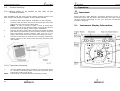
mn100 Analog Display
mn100
Analog Display
uu040 rev. 8
26
mn100 Analog Display
Maintenance and Calibration
EMC Conformance
All Tacktick equipment is designed to the best industry standards for
use in the recreational marine environment. The design and
manufacture of Tacktick equipment conforms to the appropriate
Electromagnetic Compatibility (EMC) standards. Correct installation is
required to ensure that performance is not compromised.
Important
Due to the wireless communication systems used in Micronet
instruments they are only recommended for use on boats up to 14
meters (45 ft.) which are of glass, carbon, or wooden construction.
Like any other Electronic instruments your Micronet system is
designed to serve only as an aid to navigation and it remains the
skippers responsibility to maintain a permanent watch and be aware
of developing situations.
2
25
mn100 Analog Display
Contents
Warranty Information
1
Tacktick Limited or its authorized Distributors will repair or replace a
Tacktick product free of charge where a manufacturing fault becomes
apparent within two years of the purchase date provided:
1.
2.
No unauthorized attempt has been made to repair the
product.
The product has not been misused, operated outside of its
intended environment or operated in a manner which is
incompatible with the written instructions supplied on
purchase.
Proof of purchase date is required for the warranty period to be valid.
Due to the removable nature of the Tacktick product, on board service
will only be available with prior consent from Tacktick or its authorized
Distributors.
Failure within the warranty period:
Simply return the product to your nearest authorized Tacktick
Distributor, together with proof of purchase date.
Failure outside the warranty period:
Simply return your product to the nearest authorized Tacktick
Distributor and an estimation for repair will be provided.
Authorized
Tacktick
Distributor
details
can
be
found
www.tacktick.com, or on the back of Tacktick sales brochures.
1.1
1.2
1.3
1.4
2
Introduction
Specifications
Power Management and Battery Life
Safety and Disposal
Instrument Display Information
Switching the System On and Off
Backlighting
Audible Signals and Alarms
Chapter and Page Operation
Chapter and Page Description
3
Setup and Calibration
3.1
3.2
3.3
3.4
4
4.1
-
2
2
4
4
-
5
6
6
7
8
10
-
12
12
15
14
-
16
-
18
18
19
20
21
Operation
2.1
2.2
2.3
2.4
2.5
2.6
Entering Setup and Calibration Mode
Chapter and Page Setup and Calibration
Editing Values
Setup Page Description
Seatrial and Calibration
Wind Angle and Speed Calibration
at
5
5.1
5.2
5.3
5.4
5.5
6
6.1
6.2
6.3
24
Information
Installation
Tools List & Parts
Precautions and Positioning Advise
Bracket Mounting
Surface Mounting
External Power Connections
Maintenance and Fault Finding
Care and Maintenance
Fault Finding and Technical Support
Warranty Information
-
22
22
24
1
mn100 Analog Display
Maintenance and Calibration
1 - Information
6.2.3 A single instrument flashes the battery symbol
and then
switches off.
The battery level is low on the particular instrument affected. Connect
to a 9 to 24V power source or leave in bright sunlight for 12 hours
minimum to fully recharge the instrument’s internal battery. If the
particular instrument is the system Master* then the other instruments
will sound the Lost Network Alarm. To continue using the rest of the
system power down and restart the system from another instrument.
1.1
Introduction
Your Micronet instrument is powered for life by the environment.
Although feature packed and highly visible in all conditions, current
demand is so low, and the supply so efficient, that the solar-powered
display is self sufficient. Combined with other instruments in the
Micronet range this display becomes part of a complete navigational
system.
1.2
Specifications
Height of digits:
Backlighting:
Power:
Units of display:
Alarm:
Weight:
Operating Temp.:
Frequency:
1.3
6.2.4 Low Battery Alarm Sounds.
The power level is low in the Hull Transmitter, NMEA Interface or Wind
Transmitter. On any Digital Instrument enter setup and calibration
mode (page 14) and scroll through to the Health Chapter.
7mm (0.28”)
3 levels with daylight shutoff
System-wide or local control
Solar Powered
300 hrs autonomy by day, 7 nights at brightest
backlighting, 20 nights at economy backlighting
without charge
Wind Speed
(knots, meters per second, Beaufort)
Audible Alarm for Wind
285g (0.63lbs)
-100 to +600C (140 to 1400F)
868 MHz or 905 MHz
Power Management and Battery Life
What makes your mn100 instrument possible is Tacktick’s
revolutionary approach to power management. By reducing the
amount of power being used by the electronics and maximizing the
potential of the sun to provide power, a mn100 instrument becomes a
virtually perpetual device.
Power status is indicated by two icons on the instrument display:
Battery Level
and
Check the signal levels of the Transmitters and Interface Box. Connect
the Hull Transmitter or NMEA Interface to a 9 to 24V power source for
12 hours minimum to recharge the internal battery. Leave the Wind
transmitter in bright sunlight for 12 hours minimum to recharge its
internal battery.
6.2.5 Data is shown as dashes.
The information is not been transmitted to the instrument displays.
There may be lost communication between the Wind Transmitter or
Hull transmitter and the instrument displays. On any Digital instrument
enter setup and calibration mode (page 14) and scroll through to the
Health Chapter. Check the signal levels of the Hull and Wind
Transmitters
6.2.6 Wind speed reads 0.
Information being transmitted from the Wind Transmitter is being
received with a Zero value. If the anemometer cups at the top of the
mast are turning and the Wind Speed reads 0 then there is a problem
with your Wind Transmitter.
6.2.7 No NMEA data showing on external instruments.
From any Instrument enter setup and calibration mode (page 14) and
scroll through to the Health Chapter. Check the signal level and battery
status of the NMEA Interface Box.
Charge Rate
Used together these icons will show the condition of your instrument’s
power supply.
*
2
The “Master Instrument” is the instrument which was used to power up
the entire system. This instrument may be different each time the
system is used. If you are fault finding and are uncertain which
instrument is the master the switch off the system and switch on again.
The instrument which you switched on is now the master
23
mn100 Analog Display
6
Operation
Maintenance and Fault Finding
6.1 Care and Maintenance
All Micronet products are totally sealed against water and are not
serviceable. Any attempt to take a Micronet product apart will
invalidate the warranty.
Bright
Day
Sunny
Overcast Day
To clean, use only a damp, soft cloth. No detergents, solvents or
abrasives should be used.
To avoid damaging a Micronet display unit we recommend storing in
the supplied soft pack when not in use.
6.2.1 Power Save Alarm sounds.
There has been no significant data activity on the network. The alarm
sounds to indicate that the instrument system will turn itself off. To
continue using the system press any button to cancel the alarm.
6.2.2 Lost Network Alarm sounds.
On a single instrument this indicates that the particular instrument has
lost communication with the Master*. Either there is a problem with the
Master* instrument or the instrument in question has been moved out
of effective range.
On several instruments this indicates that these instruments have lost
communication with the Master*. Either there is a problem with the
master or the Master* has been moved out of effective range. The
instruments will power down shortly after sounding the alarm to save
power.
Battery is charged and
topped up by the sun. *
and
Battery is low and being charged
by the sun.
and
Battery is charged and requires no
further charging.
and
Battery is low but maintaining it’s
level.
and
Night
If the instruments are to be stored for a long period of time before
next use (Over Winter) ensure that the batteries are fully charged
before storage. If necessary connect to a 9 to 24v power supply for
24 hrs prior to storage.
6.2 Fault Finding and Technical Support
and
and
LOW Power
and
Flashing
Battery is
charging.
charged
but
being
is
not
Battery is low with no charging.
It is recommended that the
instrument be left in daylight for
some time for the battery to
recover, or charge from an
external 9 - 24V power source. A
fully discharged battery will recharge in approximately 12 hours
of direct bright sunlight.
If using the instruments at night power usage can be reduced
dramatically by switching the Backlighting to level 1 or Off. If
Backlighting is not required on instruments located below decks it is
best to set them to “Local” Backlighting control (see page 15 –s6) so
that power is not being wasted in instruments which may not be
visible from the one being viewed.
*
If the internal battery is fully charged then it does not matter
how much the instrument is subjected to bright sunlight no further
charging is required and the Charge Rate Indicator will remain low.
If the instruments are to be stored for a long period of time
before next use (Over Winter) ensure that the batteries are
fully charged before storage. If necessary connect to a 9 to
24v power supply for 24 hrs prior to storage.
22
3
mn100 Analog Display
If there is no boat speed or change in heading registered on the
system for a period of 12 hours your Micronet instrument will switch
off to conserve power. A “POWER SAVE” alarm will sound before the
instrument system is switched off. Pressing any button within 10
seconds of the alarm sounding will allow the system to remain
switched on.
Backlighting will automatically shut down/off when operated in
daylight.
Artificial light WILL NOT recharge the battery. Placing
your Micronet instrument close to an artificial light will
seriously damage the instrument. Only recharge in natural
daylight.
Installation
5.4.3 Where access is available to the rear of the
mounting surface
This method allows for maximum security of a permanently mounted
instrument. Position the supplied Template carefully before starting.
1.
2.
3.
4.
Drill three 5mm holes marked “B” on the Template.
Screw the four M4 brass studs into the rear of the
instrument.
Place the instrument in position pushing the three studs
through the newly drilled holes.
Using the three supplied thumb nuts, secure the instrument
to the surface making sure the instrument is level before
final tightening.
Applying External Power
In cases where instruments are mounted permanently below decks it
will be necessary to apply an external power source to prevent
complete discharge of the built in battery.
Connections on the rear of the instrument allow a 9V to 24V DC power
source to be connected. Connections can be made to the vessels DC
system or a 9V battery pack may be connected . It is recommended
that permanent connection is only made when the instruments are
permanently fixed to the vessel and not when the clip brackets are
used.
Connection to a 9V (PP3) battery will fully recharge the internal
battery over a period of 24 hours.
5.5
To connect an external 9 to 24 volt power supply to the instrument
head from either a portable battery or the vessel’s existing power
system.
1.
1.4
Safety and Disposal
Your Micronet instrument contains Manganese Lithium Dioxide
batteries which should be disposed of correctly. Do not dispose of any
instrument in domestic waste. Refer to regulations in force in your
country.
If in doubt return the instrument to Tacktick Ltd. for correct disposal.
4
External Power Connections
2.
3.
3.
4.
5.
Drill two 7mm holes marked “P” on the Mounting Template
and smooth them together with a sharp knife or small file.
Pass the supply cable through the new hole and attach the
supplied crimp spade receptacles.
Remove the blanking plug from the rear of the instrument to
expose the terminals.
Taking care to connect the correct polarity push the
receptacles firmly onto the spades on the rear of the
instrument.
Mount the instrument head securely in position.
Clamp the cable securely close to the instrument.
21
mn100 Analog Display
5.4
Surface Mounting
Operation
2 – Operation
5.4.1 Where there is no access to the rear of the
mounting surface
Easy installation but will allow removal without gaining access to the
boat. Position the supplied Template carefully before starting.
1.
2.
3.
4.
Drill three 2mm holes marked “SURFACE” on the Template
Carefully snap the facia of the instrument off the main body
taking care not to drop the button pads.
HINT – It may be useful to place a piece of sticky tape
across the front of the buttons before removing the facia to
prevent them from falling out during the installation.
Remove the three captive M4 nuts from the plastic moulding
and attach the instrument to the mounting surface using the
three self tapping screws provided. Take care not to over
tighten the screws as this may cause the moulding to crack.
Check the instrument is perfectly level, carefully position the
button inserts into the correct slots and snap the facia back
into position.
Important:
Ensure that the “Auto Network” procedure described on the yellow
instruction sheet and full Setup and Calibration has been performed
correctly before attempting to use your Micronet instruments for
navigation purposes.
2.1
Instrument Display Information
5.4.2 Temporary Mounting
1.
Note:
20
Use the double sided tape provided to secure the instrument
to a suitable mounting surface. Press the instrument firmly
against the surface until secure.
This method is recommended for temporary use only.
5
mn100 Analog Display
2.2
Switching the System On and Off
To switch on your Micronet
system select any instrument
and press the
button for 2
seconds.
To switch off your Micronet
system select any instrument
and press and hold the button
for 2 seconds.
2.3
Installation
5.3
Bracket Mounting (Preferred Method)
This method allows for the easy removal of an instrument as and
when required, for either security reasons or to prevent damage or
discomfort whilst not in use.
1.
Using the three supplied M4 bolts attach the back plate to
the rear of the instrument (Fig.1).
2.
Drill three 2mm holes marked “BRACKET” on the Template
and using the supplied self tapping screws attach the clip
bracket to the mounting surface (Fig.2).
3.
Place the instrument flat against the bracket slightly higher
than the final position and slide gently down into position.
There will be a small click as the bracket secures the
instrument into position (Fig.3).
4.
To release the instrument press lightly on the bracket tab
and slide the instrument upwards (Fig.4).
Backlighting
At any stage of the instrument’s
operation press and hold for 2
seconds the
button to
access the lighting control.
Pressing the
and
buttons
will
scroll
through
setting OFF, 1, 2 and 3 whilst
changing
the
Backlighting.
Depending on the instrument
setup (see page 16 -s5),
Backlighting
on
the
whole
system or just the single
instrument will be altered.
Backlighting is automatically switched off in daylight as part of
the instrument’s power saving feature and will not operate in daylight.
6
19
mn100 Analog Display
5
Installation
5.1
Tools Required and
1. 2mm or 5mm Drill Bit (7mm
if power connection required)
2. Power Drill
3. Cross Head Screwdriver
5.2
Operation
2.4
Parts List
1.
2.
3.
4.
5.
6.
Mounting Template
Display Bracket
Mounting Screws (3)
Mounting Bolts (3)
M4 Studs & Thumbnuts (3)
Double Sided Tape
Precautions and Positioning Advice
Ensure mounting surface is flat.
Leave space between instruments for sun covers.
Leave space to remove instrument from bracket (if used).
Avoid areas where damage may occur (winch handles, feet, warps
etc.)
Select a flat, smooth, surface for mounting and use the Template
provided to select a suitable position for mounting your Micronet
instrument.
Check for clarity of vision and ease of access to the control buttons, it
is recommended that instruments are positioned such that your arm
does NOT pass through the spokes of the steering wheel when
operating the buttons.
18
Audible Signals and Alarms
At stages during its operation your Micronet instrument will beep to
indicate alarms or moments of importance.
Power-up
Once operating as part of a network the instrument
will issue a single beep as it is switched on by
pressing the
button for 2 second.
Button Press A single beep is issued each time a button is pressed
A second beep is issued after a 2 seconds hold down
of the
button.
Alarm
Continuous bursts of three beeps will indicate an
alarm. The alarm activated will be indicated on the
digital display, accompanied by the flashing
symbol. Pressing any button will silence the alarm.
Timer
A single beep will be issued at each minute of the
countdown. With 1 minute left to go a beep will sound
every 10 seconds. With 10 seconds to go a beep will
sound every second.
Countdown complete will be indicated by a single
burst of three beeps.
7
mn100 Analog Display
2.5
Setup and Calibration
Chapter and Page Operation
Instrument information is displayed in a “Chapter and Page” format
using the button to scroll through the Chapters and the and buttons
to move between Pages. The diagram below shows the information
format.
4.1.2 Wind Speed Correction
Note:
Wind Speed reading is factory calibrated to display correctly
and should not be altered unless external factors are thought
to be causing incorrect readings. Correction should only be
carried out if a known correct windspeed is available.
Press and hold the
button for 2 seconds to enter Setup
Press the
button repeatedly to scroll to the “SETUP/WIND”
Chapter
Press the
button to advance to “WIND/+0%” Page
Press the
button to enter Edit Mode
Press the
and
buttons to change the displayed value to the
required percentage.
The bottom digits will indicate the displayed Wind Speed.
Press the
button to exit Edit Mode
Press and hold the
button to exit Setup and return to normal
operation.
Default Chapter Selection
8
17
mn100 Analog Display
4 - Seatrial and Calibration
Once the Micronet Instrument system has been installed on the vessel
and Autonetworking has been completed it is necessary to carry out
calibration.
Operation
Pressing the
button at any time will move on to the next Chapter
and on scrolling through the Chapters the Page last selected in that
Chapter will be displayed. Both Chapter and Page selection will scroll
back to the first Page once a cycle has been completed.
It is not safe to use the instruments for navigational purposes
until calibration has been carried out correctly.
Wind Calibration
Both Wind Speed and Direction can be calibrated to ensure that
readings from the Wind Transmitter are displayed accurately.
4.1.1 Wind Angle Offset
Motor the vessel directly into the wind.
Press and hold the
button for 2 seconds to enter Setup
Press the
button repeatedly to scroll to the “SETUP/WIND”
Chapter
Press the
button to advance to “WIND/+0000” Page
Press the
button to enter Edit Mode
Press the
or
buttons to change the displayed value to 000.
The bottom digits will indicate the number of degrees of offset
entered.
Press the
button to exit Edit Mode
Press and hold the
button to exit Setup and return to normal
operation.
Page Selection
For a full description of each page refer to items 1 to 8 on the
following pages.
16
9
mn100 Analog Display
2.6
Chapter and Page Description
Setup and Calibration
(s6)
LITE
Tells the instrument to control the system Backlighting or
just its own Backlighting. nEt/LOC.
(s7)
SHOW
Allows the instrument to display information when NOT
installed as part of a Micronet system for demonstration
purposes only. Off/On.
(s8)
LCD
Adjusts the viewing angle and contrast of the LCD display to
improve visibility under varied mounting possibilities. 1 - 7
default 4.
(s9)
RSET
Returns all the calibration settings to the factory default
values.
3600 Wind Chapter
(1)
Apparent Wind Angle
The Actual Wind Angle with respect to the vessel as
measured by the Wind Transmitter.
and
Apparent Wind Speed
The Actual Wind Speed with respect to the vessel as
measured by the Wind Transmitter.
(2)
True Wind Angle
The True Wind Angle with respect to the vessel, calculated
by the instrument taking into account the vessels speed
through the water. Both Apparent Wind Speed, Angle and
Boat Speed must be available for this calculation.
and
True Wind Speed
The True Wind Speed with respect to the vessel, calculated
by the instrument taking into account the vessels speed
through the water. Both Apparent Wind Speed, Angle and
Boat Speed must be available for this calculation.
Health Chapter
(s10)
V / no
Displays the instrument’s Software Version, battery level and
charge rate to assist in troubleshooting and fault finding. If
the instrument is the “Master” (the one used to switch on the
system) then the number of items (nodes) in the system will
be displayed. If the instrument is a “Slave” (was switched on
by the system) then the signal strength to the “Master” will
be displayed”
(s11)
HULL
Shows the signal strength and battery level of the Hull
Transmitter to assist in troubleshooting and fault finding.
(s12)
WIND SIGNL
information)
(s13)
NMEA SIGNL (as above but for NMEA Interface information)
Magnified Wind Chapter
(3)
Magnified Apparent Wind Angle
The Actual Wind Angle with respect to the vessel as
measured by the Wind Transmitter and displayed on a 0 to
60 degree scale.
and Apparent Wind Speed (see above)
(4)
Magnified True Wind Angle
The True Wind Angle with respect to the vessel, calculated
by the instrument taking into account the vessels speed
through the water and displayed on a 0 to 60 degree scale.
Both Apparent Wind Speed, Angle and Boat Speed must be
available for this calculation.
(as
above
but
for
Wind
Transmitter
(s14 --) TYPE 4 - Further signal strength indications will be displayed
if available.
and True Wind Speed (see above)
10
15
mn100 Analog Display
3.4
Setup Page Description
Units Chapter
Press the
button quickly to edit, press the
or
to
change units and press the
button quickly to select the chosen
units. Default values are shown in bold.
(s1)
Sets the units in which ALL Wind Speed related information
is displayed. Knots or Meters per second (M/S).
Wind Chapter
Operation
VMG Chapter
(5)
True Wind Angle (see above)
and
Velocity Made good to Windward
The vessels calculated speed directly upwind. This value is
calculated by the instrument from the Boat Speed and
Apparent Wind Angle.
Beaufort Chapter
(6)
Beaufort Wind Speed
The actual wind speed over the water displayed using the
Beaufort scale, calculated by the instrument taking into
account the vessels speed through the water and compass
heading. Apparent Wind Speed, Angle, Boat Speed and
Current Heading must be available for this calculation.
and
True Wind Angle
The True Wind Angle with respect to the ground, calculated
by the instrument taking into account the vessels speed
through the water. Apparent Wind Speed, Angle, Boat Speed
and Current Heading must be available for this calculation.
Press the
button quickly to edit, press the
or
to
change units and press the
button quickly to select the
chosen units. Default values are shown in bold.
(s2)
RESP
Sets the update period of the Wind display.
Aut/Slow/Normal/Fast
(s3)
Wind Angle Offset
Aligns the displayed apparent wind angle with the actual
wind direction with respect to the boat. See page 18 for
calibration.
(s4)
Wind Speed Calibration Factor
Adds a percentage factor which corrects the information
from the Wind Transmitter and ensures the Apparent Wind
Speed is displayed correctly. See page 18 for calibration.
Options Chapter
Heading Chapter
(7)
Analogue Pointer Indicating the direction of North
and
Magnetic Heading
Current Magnetic Compass Heading of the vessel as
measured by the Compass Transducer. The value displayed
will be affected by the calibration routine for the compass.
(8)
Tack Magnetic
Magnetic Compass Heading that the vessel will follow should
it tack through the wind, calculated by the instrument.
Apparent Wind Angle and Magnetic Heading must be
available for this calculation to be made.
(9)
Analog pointer indication of True North
and
COG
The vessel’s Course Over the Ground as calculated by the
GPS Antenna.
Press the
button quickly to toggle the values between settings or
press the
button quickly to edit, press the
or
to
button quickly to select the chosen
change values and press the
value. Default values are shown in bold.
(s5)
14
AUTO nEt
Only available on the instrument which was used to power
up the system. Refer to the “Auto Network” sheet for further
information.
11
mn100 Analog Display
3 - Setup and Calibration
3.1
Entering Setup and Calibration Mode
Setup and Calibration
Editing Values
To adjust any settings press the
button. The setting will start to
flash and the
and
buttons will change the value.
To enter the Setup and Calibration menu press and hold for 2 seconds
the
button.
3.2
Chapter and Page
Setup and Calibration
Instrument
Setup
and
Calibration is displayed in a
“Chapter and Page” format
using the
button to scroll
through the Chapters and the
and
buttons to move
between Pages. The diagram
below shows the information
format.
Note:
12
Unlike
normal
operation you must
scroll to the Chapter
heading page before
moving to another
chapter.
13
mn100 Analog Display
3.4
Setup Page Description
Units Chapter
Press the
button quickly to edit, press the
or
to
change units and press the
button quickly to select the chosen
units. Default values are shown in bold.
(s1)
Sets the units in which ALL Wind Speed related information
is displayed. Knots or Meters per second (M/S).
Wind Chapter
Operation
VMG Chapter
(5)
True Wind Angle (see above)
and
Velocity Made good to Windward
The vessels calculated speed directly upwind. This value is
calculated by the instrument from the Boat Speed and
Apparent Wind Angle.
Beaufort Chapter
(6)
Beaufort Wind Speed
The actual wind speed over the water displayed using the
Beaufort scale, calculated by the instrument taking into
account the vessels speed through the water and compass
heading. Apparent Wind Speed, Angle, Boat Speed and
Current Heading must be available for this calculation.
and
True Wind Angle
The True Wind Angle with respect to the ground, calculated
by the instrument taking into account the vessels speed
through the water. Apparent Wind Speed, Angle, Boat Speed
and Current Heading must be available for this calculation.
Press the
button quickly to edit, press the
or
to
change units and press the
button quickly to select the
chosen units. Default values are shown in bold.
(s2)
RESP
Sets the update period of the Wind display.
Aut/Slow/Normal/Fast
(s3)
Wind Angle Offset
Aligns the displayed apparent wind angle with the actual
wind direction with respect to the boat. See page 18 for
calibration.
(s4)
Wind Speed Calibration Factor
Adds a percentage factor which corrects the information
from the Wind Transmitter and ensures the Apparent Wind
Speed is displayed correctly. See page 18 for calibration.
Options Chapter
Heading Chapter
(7)
Analogue Pointer Indicating the direction of North
and
Magnetic Heading
Current Magnetic Compass Heading of the vessel as
measured by the Compass Transducer. The value displayed
will be affected by the calibration routine for the compass.
(8)
Tack Magnetic
Magnetic Compass Heading that the vessel will follow should
it tack through the wind, calculated by the instrument.
Apparent Wind Angle and Magnetic Heading must be
available for this calculation to be made.
(9)
Analog pointer indication of True North
and
COG
The vessel’s Course Over the Ground as calculated by the
GPS Antenna.
Press the
button quickly to toggle the values between settings or
press the
button quickly to edit, press the
or
to
button quickly to select the chosen
change values and press the
value. Default values are shown in bold.
(s5)
14
AUTO nEt
Only available on the instrument which was used to power
up the system. Refer to the “Auto Network” sheet for further
information.
11
mn100 Analog Display
2.6
Chapter and Page Description
Setup and Calibration
(s6)
LITE
Tells the instrument to control the system Backlighting or
just its own Backlighting. nEt/LOC.
(s7)
SHOW
Allows the instrument to display information when NOT
installed as part of a Micronet system for demonstration
purposes only. Off/On.
(s8)
LCD
Adjusts the viewing angle and contrast of the LCD display to
improve visibility under varied mounting possibilities. 1 - 7
default 4.
(s9)
RSET
Returns all the calibration settings to the factory default
values.
3600 Wind Chapter
(1)
Apparent Wind Angle
The Actual Wind Angle with respect to the vessel as
measured by the Wind Transmitter.
and
Apparent Wind Speed
The Actual Wind Speed with respect to the vessel as
measured by the Wind Transmitter.
(2)
True Wind Angle
The True Wind Angle with respect to the vessel, calculated
by the instrument taking into account the vessels speed
through the water. Both Apparent Wind Speed, Angle and
Boat Speed must be available for this calculation.
and
True Wind Speed
The True Wind Speed with respect to the vessel, calculated
by the instrument taking into account the vessels speed
through the water. Both Apparent Wind Speed, Angle and
Boat Speed must be available for this calculation.
Health Chapter
(s10)
V / no
Displays the instrument’s Software Version, battery level and
charge rate to assist in troubleshooting and fault finding. If
the instrument is the “Master” (the one used to switch on the
system) then the number of items (nodes) in the system will
be displayed. If the instrument is a “Slave” (was switched on
by the system) then the signal strength to the “Master” will
be displayed”
(s11)
HULL
Shows the signal strength and battery level of the Hull
Transmitter to assist in troubleshooting and fault finding.
(s12)
WIND SIGNL
information)
(s13)
NMEA SIGNL (as above but for NMEA Interface information)
Magnified Wind Chapter
(3)
Magnified Apparent Wind Angle
The Actual Wind Angle with respect to the vessel as
measured by the Wind Transmitter and displayed on a 0 to
60 degree scale.
and Apparent Wind Speed (see above)
(4)
Magnified True Wind Angle
The True Wind Angle with respect to the vessel, calculated
by the instrument taking into account the vessels speed
through the water and displayed on a 0 to 60 degree scale.
Both Apparent Wind Speed, Angle and Boat Speed must be
available for this calculation.
(as
above
but
for
Wind
Transmitter
(s14 --) TYPE 4 - Further signal strength indications will be displayed
if available.
and True Wind Speed (see above)
10
15
mn100 Analog Display
4 - Seatrial and Calibration
Once the Micronet Instrument system has been installed on the vessel
and Autonetworking has been completed it is necessary to carry out
calibration.
Operation
Pressing the
button at any time will move on to the next Chapter
and on scrolling through the Chapters the Page last selected in that
Chapter will be displayed. Both Chapter and Page selection will scroll
back to the first Page once a cycle has been completed.
It is not safe to use the instruments for navigational purposes
until calibration has been carried out correctly.
Wind Calibration
Both Wind Speed and Direction can be calibrated to ensure that
readings from the Wind Transmitter are displayed accurately.
4.1.1 Wind Angle Offset
Motor the vessel directly into the wind.
Press and hold the
button for 2 seconds to enter Setup
Press the
button repeatedly to scroll to the “SETUP/WIND”
Chapter
Press the
button to advance to “WIND/+0000” Page
Press the
button to enter Edit Mode
Press the
or
buttons to change the displayed value to 000.
The bottom digits will indicate the number of degrees of offset
entered.
Press the
button to exit Edit Mode
Press and hold the
button to exit Setup and return to normal
operation.
Page Selection
For a full description of each page refer to items 1 to 8 on the
following pages.
16
9
mn100 Analog Display
2.5
Setup and Calibration
Chapter and Page Operation
Instrument information is displayed in a “Chapter and Page” format
using the button to scroll through the Chapters and the and buttons
to move between Pages. The diagram below shows the information
format.
4.1.2 Wind Speed Correction
Note:
Wind Speed reading is factory calibrated to display correctly
and should not be altered unless external factors are thought
to be causing incorrect readings. Correction should only be
carried out if a known correct windspeed is available.
Press and hold the
button for 2 seconds to enter Setup
Press the
button repeatedly to scroll to the “SETUP/WIND”
Chapter
Press the
button to advance to “WIND/+0%” Page
Press the
button to enter Edit Mode
Press the
and
buttons to change the displayed value to the
required percentage.
The bottom digits will indicate the displayed Wind Speed.
Press the
button to exit Edit Mode
Press and hold the
button to exit Setup and return to normal
operation.
Default Chapter Selection
8
17
mn100 Analog Display
5
Installation
5.1
Tools Required and
1. 2mm or 5mm Drill Bit (7mm
if power connection required)
2. Power Drill
3. Cross Head Screwdriver
5.2
Operation
2.4
Parts List
1.
2.
3.
4.
5.
6.
Mounting Template
Display Bracket
Mounting Screws (3)
Mounting Bolts (3)
M4 Studs & Thumbnuts (3)
Double Sided Tape
Precautions and Positioning Advice
Ensure mounting surface is flat.
Leave space between instruments for sun covers.
Leave space to remove instrument from bracket (if used).
Avoid areas where damage may occur (winch handles, feet, warps
etc.)
Select a flat, smooth, surface for mounting and use the Template
provided to select a suitable position for mounting your Micronet
instrument.
Check for clarity of vision and ease of access to the control buttons, it
is recommended that instruments are positioned such that your arm
does NOT pass through the spokes of the steering wheel when
operating the buttons.
18
Audible Signals and Alarms
At stages during its operation your Micronet instrument will beep to
indicate alarms or moments of importance.
Power-up
Once operating as part of a network the instrument
will issue a single beep as it is switched on by
pressing the
button for 2 second.
Button Press A single beep is issued each time a button is pressed
A second beep is issued after a 2 seconds hold down
of the
button.
Alarm
Continuous bursts of three beeps will indicate an
alarm. The alarm activated will be indicated on the
digital display, accompanied by the flashing
symbol. Pressing any button will silence the alarm.
Timer
A single beep will be issued at each minute of the
countdown. With 1 minute left to go a beep will sound
every 10 seconds. With 10 seconds to go a beep will
sound every second.
Countdown complete will be indicated by a single
burst of three beeps.
7
mn100 Analog Display
2.2
Switching the System On and Off
To switch on your Micronet
system select any instrument
and press the
button for 2
seconds.
To switch off your Micronet
system select any instrument
and press and hold the button
for 2 seconds.
2.3
Installation
5.3
Bracket Mounting (Preferred Method)
This method allows for the easy removal of an instrument as and
when required, for either security reasons or to prevent damage or
discomfort whilst not in use.
1.
Using the three supplied M4 bolts attach the back plate to
the rear of the instrument (Fig.1).
2.
Drill three 2mm holes marked “BRACKET” on the Template
and using the supplied self tapping screws attach the clip
bracket to the mounting surface (Fig.2).
3.
Place the instrument flat against the bracket slightly higher
than the final position and slide gently down into position.
There will be a small click as the bracket secures the
instrument into position (Fig.3).
4.
To release the instrument press lightly on the bracket tab
and slide the instrument upwards (Fig.4).
Backlighting
At any stage of the instrument’s
operation press and hold for 2
seconds the
button to
access the lighting control.
Pressing the
and
buttons
will
scroll
through
setting OFF, 1, 2 and 3 whilst
changing
the
Backlighting.
Depending on the instrument
setup (see page 16 -s5),
Backlighting
on
the
whole
system or just the single
instrument will be altered.
Backlighting is automatically switched off in daylight as part of
the instrument’s power saving feature and will not operate in daylight.
6
19
mn100 Analog Display
5.4
Surface Mounting
Operation
2 – Operation
5.4.1 Where there is no access to the rear of the
mounting surface
Easy installation but will allow removal without gaining access to the
boat. Position the supplied Template carefully before starting.
1.
2.
3.
4.
Drill three 2mm holes marked “SURFACE” on the Template
Carefully snap the facia of the instrument off the main body
taking care not to drop the button pads.
HINT – It may be useful to place a piece of sticky tape
across the front of the buttons before removing the facia to
prevent them from falling out during the installation.
Remove the three captive M4 nuts from the plastic moulding
and attach the instrument to the mounting surface using the
three self tapping screws provided. Take care not to over
tighten the screws as this may cause the moulding to crack.
Check the instrument is perfectly level, carefully position the
button inserts into the correct slots and snap the facia back
into position.
Important:
Ensure that the “Auto Network” procedure described on the yellow
instruction sheet and full Setup and Calibration has been performed
correctly before attempting to use your Micronet instruments for
navigation purposes.
2.1
Instrument Display Information
5.4.2 Temporary Mounting
1.
Note:
20
Use the double sided tape provided to secure the instrument
to a suitable mounting surface. Press the instrument firmly
against the surface until secure.
This method is recommended for temporary use only.
5
mn100 Analog Display
If there is no boat speed or change in heading registered on the
system for a period of 12 hours your Micronet instrument will switch
off to conserve power. A “POWER SAVE” alarm will sound before the
instrument system is switched off. Pressing any button within 10
seconds of the alarm sounding will allow the system to remain
switched on.
Backlighting will automatically shut down/off when operated in
daylight.
Artificial light WILL NOT recharge the battery. Placing
your Micronet instrument close to an artificial light will
seriously damage the instrument. Only recharge in natural
daylight.
Installation
5.4.3 Where access is available to the rear of the
mounting surface
This method allows for maximum security of a permanently mounted
instrument. Position the supplied Template carefully before starting.
1.
2.
3.
4.
Drill three 5mm holes marked “B” on the Template.
Screw the four M4 brass studs into the rear of the
instrument.
Place the instrument in position pushing the three studs
through the newly drilled holes.
Using the three supplied thumb nuts, secure the instrument
to the surface making sure the instrument is level before
final tightening.
Applying External Power
In cases where instruments are mounted permanently below decks it
will be necessary to apply an external power source to prevent
complete discharge of the built in battery.
Connections on the rear of the instrument allow a 9V to 24V DC power
source to be connected. Connections can be made to the vessels DC
system or a 9V battery pack may be connected . It is recommended
that permanent connection is only made when the instruments are
permanently fixed to the vessel and not when the clip brackets are
used.
Connection to a 9V (PP3) battery will fully recharge the internal
battery over a period of 24 hours.
5.5
To connect an external 9 to 24 volt power supply to the instrument
head from either a portable battery or the vessel’s existing power
system.
1.
1.4
Safety and Disposal
Your Micronet instrument contains Manganese Lithium Dioxide
batteries which should be disposed of correctly. Do not dispose of any
instrument in domestic waste. Refer to regulations in force in your
country.
If in doubt return the instrument to Tacktick Ltd. for correct disposal.
4
External Power Connections
2.
3.
3.
4.
5.
Drill two 7mm holes marked “P” on the Mounting Template
and smooth them together with a sharp knife or small file.
Pass the supply cable through the new hole and attach the
supplied crimp spade receptacles.
Remove the blanking plug from the rear of the instrument to
expose the terminals.
Taking care to connect the correct polarity push the
receptacles firmly onto the spades on the rear of the
instrument.
Mount the instrument head securely in position.
Clamp the cable securely close to the instrument.
21
mn100 Analog Display
6
Operation
Maintenance and Fault Finding
6.1 Care and Maintenance
All Micronet products are totally sealed against water and are not
serviceable. Any attempt to take a Micronet product apart will
invalidate the warranty.
Bright
Day
Sunny
Overcast Day
To clean, use only a damp, soft cloth. No detergents, solvents or
abrasives should be used.
To avoid damaging a Micronet display unit we recommend storing in
the supplied soft pack when not in use.
6.2.1 Power Save Alarm sounds.
There has been no significant data activity on the network. The alarm
sounds to indicate that the instrument system will turn itself off. To
continue using the system press any button to cancel the alarm.
6.2.2 Lost Network Alarm sounds.
On a single instrument this indicates that the particular instrument has
lost communication with the Master*. Either there is a problem with the
Master* instrument or the instrument in question has been moved out
of effective range.
On several instruments this indicates that these instruments have lost
communication with the Master*. Either there is a problem with the
master or the Master* has been moved out of effective range. The
instruments will power down shortly after sounding the alarm to save
power.
Battery is charged and
topped up by the sun. *
and
Battery is low and being charged
by the sun.
and
Battery is charged and requires no
further charging.
and
Battery is low but maintaining it’s
level.
and
Night
If the instruments are to be stored for a long period of time before
next use (Over Winter) ensure that the batteries are fully charged
before storage. If necessary connect to a 9 to 24v power supply for
24 hrs prior to storage.
6.2 Fault Finding and Technical Support
and
and
LOW Power
and
Flashing
Battery is
charging.
charged
but
being
is
not
Battery is low with no charging.
It is recommended that the
instrument be left in daylight for
some time for the battery to
recover, or charge from an
external 9 - 24V power source. A
fully discharged battery will recharge in approximately 12 hours
of direct bright sunlight.
If using the instruments at night power usage can be reduced
dramatically by switching the Backlighting to level 1 or Off. If
Backlighting is not required on instruments located below decks it is
best to set them to “Local” Backlighting control (see page 15 –s6) so
that power is not being wasted in instruments which may not be
visible from the one being viewed.
*
If the internal battery is fully charged then it does not matter
how much the instrument is subjected to bright sunlight no further
charging is required and the Charge Rate Indicator will remain low.
If the instruments are to be stored for a long period of time
before next use (Over Winter) ensure that the batteries are
fully charged before storage. If necessary connect to a 9 to
24v power supply for 24 hrs prior to storage.
22
3
mn100 Analog Display
Maintenance and Calibration
1 - Information
6.2.3 A single instrument flashes the battery symbol
and then
switches off.
The battery level is low on the particular instrument affected. Connect
to a 9 to 24V power source or leave in bright sunlight for 12 hours
minimum to fully recharge the instrument’s internal battery. If the
particular instrument is the system Master* then the other instruments
will sound the Lost Network Alarm. To continue using the rest of the
system power down and restart the system from another instrument.
1.1
Introduction
Your Micronet instrument is powered for life by the environment.
Although feature packed and highly visible in all conditions, current
demand is so low, and the supply so efficient, that the solar-powered
display is self sufficient. Combined with other instruments in the
Micronet range this display becomes part of a complete navigational
system.
1.2
Specifications
Height of digits:
Backlighting:
Power:
Units of display:
Alarm:
Weight:
Operating Temp.:
Frequency:
1.3
6.2.4 Low Battery Alarm Sounds.
The power level is low in the Hull Transmitter, NMEA Interface or Wind
Transmitter. On any Digital Instrument enter setup and calibration
mode (page 14) and scroll through to the Health Chapter.
7mm (0.28”)
3 levels with daylight shutoff
System-wide or local control
Solar Powered
300 hrs autonomy by day, 7 nights at brightest
backlighting, 20 nights at economy backlighting
without charge
Wind Speed
(knots, meters per second, Beaufort)
Audible Alarm for Wind
285g (0.63lbs)
-100 to +600C (140 to 1400F)
868 MHz or 905 MHz
Power Management and Battery Life
What makes your mn100 instrument possible is Tacktick’s
revolutionary approach to power management. By reducing the
amount of power being used by the electronics and maximizing the
potential of the sun to provide power, a mn100 instrument becomes a
virtually perpetual device.
Power status is indicated by two icons on the instrument display:
Battery Level
and
Check the signal levels of the Transmitters and Interface Box. Connect
the Hull Transmitter or NMEA Interface to a 9 to 24V power source for
12 hours minimum to recharge the internal battery. Leave the Wind
transmitter in bright sunlight for 12 hours minimum to recharge its
internal battery.
6.2.5 Data is shown as dashes.
The information is not been transmitted to the instrument displays.
There may be lost communication between the Wind Transmitter or
Hull transmitter and the instrument displays. On any Digital instrument
enter setup and calibration mode (page 14) and scroll through to the
Health Chapter. Check the signal levels of the Hull and Wind
Transmitters
6.2.6 Wind speed reads 0.
Information being transmitted from the Wind Transmitter is being
received with a Zero value. If the anemometer cups at the top of the
mast are turning and the Wind Speed reads 0 then there is a problem
with your Wind Transmitter.
6.2.7 No NMEA data showing on external instruments.
From any Instrument enter setup and calibration mode (page 14) and
scroll through to the Health Chapter. Check the signal level and battery
status of the NMEA Interface Box.
Charge Rate
Used together these icons will show the condition of your instrument’s
power supply.
*
2
The “Master Instrument” is the instrument which was used to power up
the entire system. This instrument may be different each time the
system is used. If you are fault finding and are uncertain which
instrument is the master the switch off the system and switch on again.
The instrument which you switched on is now the master
23
mn100 Analog Display
Contents
Warranty Information
1
Tacktick Limited or its authorized Distributors will repair or replace a
Tacktick product free of charge where a manufacturing fault becomes
apparent within two years of the purchase date provided:
1.
2.
No unauthorized attempt has been made to repair the
product.
The product has not been misused, operated outside of its
intended environment or operated in a manner which is
incompatible with the written instructions supplied on
purchase.
Proof of purchase date is required for the warranty period to be valid.
Due to the removable nature of the Tacktick product, on board service
will only be available with prior consent from Tacktick or its authorized
Distributors.
Failure within the warranty period:
Simply return the product to your nearest authorized Tacktick
Distributor, together with proof of purchase date.
Failure outside the warranty period:
Simply return your product to the nearest authorized Tacktick
Distributor and an estimation for repair will be provided.
Authorized
Tacktick
Distributor
details
can
be
found
www.tacktick.com, or on the back of Tacktick sales brochures.
1.1
1.2
1.3
1.4
2
Introduction
Specifications
Power Management and Battery Life
Safety and Disposal
Instrument Display Information
Switching the System On and Off
Backlighting
Audible Signals and Alarms
Chapter and Page Operation
Chapter and Page Description
3
Setup and Calibration
3.1
3.2
3.3
3.4
4
4.1
-
2
2
4
4
-
5
6
6
7
8
10
-
12
12
15
14
-
16
-
18
18
19
20
21
Operation
2.1
2.2
2.3
2.4
2.5
2.6
Entering Setup and Calibration Mode
Chapter and Page Setup and Calibration
Editing Values
Setup Page Description
Seatrial and Calibration
Wind Angle and Speed Calibration
at
5
5.1
5.2
5.3
5.4
5.5
6
6.1
6.2
6.3
24
Information
Installation
Tools List & Parts
Precautions and Positioning Advise
Bracket Mounting
Surface Mounting
External Power Connections
Maintenance and Fault Finding
Care and Maintenance
Fault Finding and Technical Support
Warranty Information
-
22
22
24
1