1
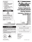
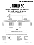
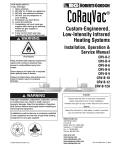
EP-100 Pump Installation, Operation & Service Manual WARNING Improper installation, adjustment, alteration, service or maintenance can result in death, injury or property damage. Read the installation, operation and service manual thoroughly before installing or servicing this equipment. Installation must be done by a contractor qualified in the installation and service of gas-fired heating equipment or your gas supplier. Installer Please take the time to read and understand these instructions prior to any installation. Installer must give a copy of this manual to the owner. Owner Keep this manual in a safe place to provide your serviceman with information should it become necessary. Roberts-Gordon Roberts-Gordon Canada Inc. 1250 William Street P.O. Box 44 Buffalo, New York 14240-0044 Telephone: 716.852.4400 Fax: 716.852.0854 Toll Free: 800.828.7450 241 South Service Road West Grimsby, Ontario L3M 1Y7 Canada Telephone: 905.945.5403 Fax: 905.945.0511 http://www.rg-inc.com © Copyright 2001 Roberts-Gordon P/N 127201NA REV.B 01/00 TABLE OF CONTENTS TABLE OF FIGURES 1. Safety . . . . . . . . . . . . . . . . . . . . . . . . . . . . . . . . . . . .1 Figure 1 . . . . . . . . . . . . . . . . . . . . . . . . . . . . . . . . . . .4 Your Safety is Important to Us . . . . . . . . . . . . . . . . .1 Figure 2 . . . . . . . . . . . . . . . . . . . . . . . . . . . . . . . . . . .4 Questions, Comments or Suggestions . . . . . . . . . . .1 Figure 3 . . . . . . . . . . . . . . . . . . . . . . . . . . . . . . . . . . .4 2. Unpacking the Pump . . . . . . . . . . . . . . . . . . . . . . .3 Figure 4 . . . . . . . . . . . . . . . . . . . . . . . . . . . . . . . . . . .5 Contents of EP-100 Pump . . . . . . . . . . . . . . . . . . . .3 Figure 5 . . . . . . . . . . . . . . . . . . . . . . . . . . . . . . . . . . .6 Unpack Pump . . . . . . . . . . . . . . . . . . . . . . . . . . . . . .3 Figure 6 . . . . . . . . . . . . . . . . . . . . . . . . . . . . . . . . . . .7 3. Pump Assembly Instructions . . . . . . . . . . . . . . . . .4 Figure 7 . . . . . . . . . . . . . . . . . . . . . . . . . . . . . . . . . . .8 Determine Orientation of Pump Scroll . . . . . . . . . . . .4 Step 1 . . . . . . . . . . . . . . . . . . . . . . . . . . . . . . . . . . . .4 Step 2 . . . . . . . . . . . . . . . . . . . . . . . . . . . . . . . . . . . .5 Step 3 . . . . . . . . . . . . . . . . . . . . . . . . . . . . . . . . . . . .6 Step 4 . . . . . . . . . . . . . . . . . . . . . . . . . . . . . . . . . . . .6 Figure 8 . . . . . . . . . . . . . . . . . . . . . . . . . . . . . . . . . . .9 Figure 9 . . . . . . . . . . . . . . . . . . . . . . . . . . . . . . . . . . .10 Figure 10 . . . . . . . . . . . . . . . . . . . . . . . . . . . . . . . . . .10 Figure 11 . . . . . . . . . . . . . . . . . . . . . . . . . . . . . . . . . .12 4. Motor Wiring . . . . . . . . . . . . . . . . . . . . . . . . . . . . . .8 Figure 12 . . . . . . . . . . . . . . . . . . . . . . . . . . . . . . . . . .13 Prior to Installation . . . . . . . . . . . . . . . . . . . . . . . . . .8 Figure 13 . . . . . . . . . . . . . . . . . . . . . . . . . . . . . . . . . .16 5. Pump Mounting Instructions . . . . . . . . . . . . . . . . .9 Mounting Platform (Angle Assembly) . . . . . . . . . . . .9 Wall Mounting . . . . . . . . . . . . . . . . . . . . . . . . . . . . . .9 Mounting Platform (Angle Assembly) . . . . . . . . . . . .10 Mounting Platform (Optional Platform Assembly) . . .10 6. Pump Venting Instructions . . . . . . . . . . . . . . . . . .11 Venting General Requirements . . . . . . . . . . . . . . . . .11 Venting the Pump . . . . . . . . . . . . . . . . . . . . . . . . . . .11 7. Service Instructions . . . . . . . . . . . . . . . . . . . . . . . .14 Change Motor/ Impeller . . . . . . . . . . . . . . . . . . . . . . .14 8. Replacement Parts . . . . . . . . . . . . . . . . . . . . . . . . .16 9. Limited Warranty . . . . . . . . . . . . . . . . . . . . . . . . . . .17 © 2002 All rights reserved. No part of this work covered by the copyrights herein may be reproduced or copied in any form or by any means - graphic, electronic, or mechanical, including photocopying, recording, taping or information storage and retrieval systems - without the written permission of Roberts-Gordon. Printed in U.S.A. SECTION 1: SAFETY Safety Your Safety is Important to Us This symbol is used throughout these instructions to notify you of possible fire, electrical or shock hazards Please pay special attention when reading and following the warnings. WARNING WARNING Electrical Shock Hazard Vacuum pump must be installed and grounded according to national codes. Improper installation, adjustment, alteration, service or maintenance will result in death, injury or property damage. Read the installation, operation and service manual carefully before installing or servicing this equipment. Disconnect electrical power before installation or service. Do not attempt to operate the vacuum pump until all steps of the installation have been accomplished. Failure to follow these instructions can result in death, injury or property damage. For assistance or additional information, consult a contractor qualified in the installation and service of gas-fired heating equipment or your gas supplier. Failure to follow these instructions will result in death, injury or property damage. Questions, Comments or Suggestions In the United States: Roberts-Gordon 1250 William Street P.O. Box 44 Buffalo, New York 14240-0044 Telephone: Fax: Toll Free: Home Page: 716.852.4400 716.852.0854 800.828.7450 www.rg-inc.com In Canada: Roberts-Gordon Canada Inc. 241 South Service Road West Grimsby, Ontario L3M 1Y7 Telephone: 905.945.5403 Fax: 905.945.0511 Home Page: www.rg-inc.com 1 EP-100 PUMP INSTALLATION, OPERATION AND SERVICE MANUAL Unpacking the Pump Contents of the EP-100 Pump Package Box 1 of 2: Part number 127102US Description Qty. Pump Frame, Motor and Impeller Assembly . . . . . . . . . . . . . . .1 CORAYVAC® Installation Manual . . . . . . . . . . . . . . . . . . . . . . . . . .1 Box 2 of 2: 02724200 02757001 91901300 91907300 91412800 92311600 Inlet Flange Assembly . . . . . . . . . . . . . . . . . . . . . . . . . . . . . . . . . . .1 Blower Housing (Scroll) . . . . . . . . . . . . . . . . . . . . . . . . . . . . . . . . . .1 Pump Boot Clamps . . . . . . . . . . . . . . . . . . . . . . . . . . . . . . . . . . . . .4 2" S Hooks . . . . . . . . . . . . . . . . . . . . . . . . . . . . . . . . . . . . . . . . . . . . . .3 Pump Boots . . . . . . . . . . . . . . . . . . . . . . . . . . . . . . . . . . . . . . . . . . . . .2 #10-24 Keps Locknuts . . . . . . . . . . . . . . . . . . . . . . . . . . . . . . . . . .12 90430600 02757500 01365400 Vacuum Proving Switch . . . . . . . . . . . . . . . . . . . . . . . . . . . . . . . . . .1 Motor Shaft Seal . . . . . . . . . . . . . . . . . . . . . . . . . . . . . . . . . . . . . . . . .1 Bird Screen . . . . . . . . . . . . . . . . . . . . . . . . . . . . . . . . . . . . . . . . . . . . .1 127201NA EP-100 Installation, Operation and Service Manual . . . . . . . .1 2 SECTION 1: UNPACKING THE VACUUM PUMP Unpacking the Pump Unpack the Pump Examine shipping cartons for external damage. Note any damage in the presence of the carrier. Have the carrier initial the "noted" Bill of Lading. Orient vacuum pump shipping cartons with arrows on cartons pointing upward. Open cartons and remove packing inserts. Carefully remove vacuum pump components from the shipping cartons. CAUTION Do not lift the vacuum pump assembly by grasping the impeller. Lift assembly by gripping metal pump frame. This pump has been tested prior to packing. The impeller was dynamically balanced before assembly and requires care in handling to avoid damage. Failure to follow these instructions can result in product damage. Unpack Pump DANGER DANGER Risque de blessures graves Severe Injury Hazard Install guard before operating high speed rotating impeller. Installer la protection avant de faire fonctionner limpulseur rotatif de haute vitesse. Keep hands, fingers and clothing away from inlet and outlet. Tenir les mains, les doigts et les vêtements à lécart des prises dentrée et de sortie. Install and operate equipment according to installation manual. Installer et opérer lappareil suivant les indications contenues dans le manuel dinstallation. Failure to follow these instructions will result in death or severe injury. © Si vous ne suivez pas ces instructions, vous risquez la mort ou des blessures graves. Printed in the U.S.A./ Imprimé aux États-Unis P/N 91012100 Rev. A 3 EP-100 PUMP INSTALLATION, OPERATION AND SERVICE MANUAL Pump Assembly Instructions Determine Orientation of Pump Scroll An arrow is affixed to the outside of the pump scroll to indicate the direction of rotation of the impeller. The standard rotation of the impeller is in the counterclockwise direction. Rotation of the impeller is as viewed from the rear of the motor as shown in the Figure below. Note that the pump scroll outlet must always be positioned at the bottom horizontal position. Arrow showing direction of rotation (located on front of scroll housing) OUTLET OUTLET Figure 1 Clockwise Rotation (Available) Step 1 Figure 2 Counterclockwise Rotation (Standard) a. After determining the correct orientation of the pump scroll outlet, attach the pump scroll to the pump frame using the #10-24 Keps locknuts provided. b. Spin the impeller to be sure that adequate clearance is maintained between the impeller blades and the body of the pump scroll. Pump Scroll Vacuum Proving Switch 1/8" NPT Inlet Flange Assembly Impeller Rubber Mounts (P/N 91906100) Figure 3 4 Partial End View SECTION 3: VACUUM PUMP ASEMBLY INSTRUCTIONS Pump Assembly Instructions Step 2 Following installation of the pump scroll to the pump frame, attach the inlet plate assembly to the pump scroll as follows using the #10-24 Keps locknuts provided. Step 3 This vacuum pump is equipped with a restricter assembly which is used as a means of setting the system vacuum. See the appropriate system installation manual for additional information. a. When the pump is installed, be certain to lock the damper in the full open position with the (1/4"-20) Hex Head bolt washers, and 5/16" flatwasher. (See Page 5, Figure 4). b. The inlet flange assembly is provided with a 1/8" N.P.T. tapping. This is to be located at the top and used for connection of the Vacuum Proving Switch (P/N 90430600) (See Page 4, Figure 3). 1/4"-20 x 1/2 Hex Head Bolt (P/N 93413008) Damper Support Ass’y (P/N 01329500) 1/4" Ext. Tooth Lock Washer (P/N 96211500) Restricter Assembly (P/N 01327500) 5/16" Flat Washer (P/N 95211600) Inlet Flange Ass'y (P/N 02724200) Figure 4 5 EP-100 PUMP INSTALLATION, OPERATION AND SERVICE MANUAL Pump Assembly Instructions Step 4 The Motor Shaft Seal (P/N 02757500) eliminates air leakage around the motor shaft and reduces the associated noise. Install the motor shaft seal as follows: a. Separate the motor shaft seal at the pre-cut score line. b. Wrap the shaft seal around the motor shaft hub as shown above. c. Secure the shaft seal in position with the adhesive strip provided. WARNING Disconnect electrical power before installation or service. Failure to follow these instructions can result in death, injury or property damage. Motor Shaft Seal (P/N 02757500) Pump Frame Impeller (P/N 02791601) Motor (P/N 90604600) Inlet Plate Assembly (P/N 02724200) Motor Shaft Hub Figure 5 6 Pump Scroll (P/N 02757001) SECTION 4: MOTOR WIRING Motor Wiring WARNING Electrical Shock Hazard Disconnect electrical power before installation or service. Failure to follow these instructions can result in death or electrical shock. IMPORTANT: Improper rotation of the impeller can produce only half of the vacuum required for proper system operation. Prior to Installation Prior to installing the pump into the heating system, it is recommended that operation and proper rotation of the impeller is verified. As standard, the motor is wired for single-phase, 115V, 60 Hz operation. However, the motor can be rewired for 230V operation by changing the motor connections as indicated by the diagram on the motor connection box cover. Motor rotation can be changed from counterclockwise to clockwise as shown in the illustration below. Wire the vacuum proving switch per the CORAYVAC® or VANTAGE®EV Installation, Operation and Service Manuals. Or an g e d Re n ow Br 115V Power Supply (Control Panel or Relay) Black Yellow Neutral (-) White Magnetek TENV Motor: To reverse rotation, interchange black and red leads). Yel low/ Black Hot (+) Ground Screw Motor Junction Box Figure 6 7 EP-100 PUMP INSTALLATION, OPERATION AND SERVICE MANUAL Pump Mounting Instructions Suspension Mounting - Chain Mounting WARNING Securely hang vacuum pump according to this Installation, Operation, and Service Manual. Failure to follow these instructions can result in death, injury or property damage. The standard method of mounting the EP-100 vacuum pump is suspending it from a chain and venting through the roof. Chain 3/16" or Larger (Not Supplied) Figure 7 8 "S" Hook (P/N 91907300) (3 Supplied) SECTION 4: MOTOR WIRING Pump Mounting Instructions Wall Mounting Platform - Angle Assembly The alternate method of mounting the EP-100 vacuum pump is on an outside wall and venting directly through the wall. The optional Mounting Angle Package P/N 01312102 must be ordered if this method is used. (P/N 95211600) Flat Washer (P/N 96411600) Spring Lock Washer (P/N 92113900) Hex Nut (P/N 01365000) Mounting Angle (P/N 93413912) Hex Head Screw #5/16-18 X 3/4 (P/N 95211600) Flat Washer Figure 8 9 EP-100 PUMP INSTALLATION, OPERATION AND SERVICE MANUAL Pump Mounting Instructions Mounting Platform (Angle Assembly) Vacuum pump may be mounted by using mounting angles as shown in view "A" or "B". 11.5" 7" "A" "B" NOTE: Typical assembly shown. Two (2) assemblies per each vacuum pump required. 4" X 8" Boot 5/8" Diameter Mounitng Holes 7" 4" 5-6" Motor 10" 10.25" 4" X 8" Boot 3.75" 7.5" Vacuum Proving Switch Thimble (if applicable) 11.5" 7"- 8" Mounting Angle Assembly (Standard) 5-6" Tailpipe SIDE VIEW TOP VIEW Figure 9 Mounting Platform (Optional Platform Assembly) If mounting on an outside wall is not practical, it may be mounted on a platform suspended from the ceiling, or for noise reduction, in an enclosure. (P/N 01365000) Mounting Angle (4) (P/N 96411600) Spring Lock Washer (P/N 95211600) Flat Washer (P/N 92113900) Hex Nut 11.5" or 7" Figure 10 10 (P/N 95211600) Flat Washer (P/N 93413912) Hex Head Screw #5/16-18 X 3/4 SECTION 6: VACUUM PUMP VENTING INSTRUCTIONS Pump Venting Instructions WARNING Carbon Monoxide Hazard Vacuum pump must be vented to the outside. Vacuum pump must be installed according to this Installation, Operation, and Service Manual. Failure to follow these instructions will result in death or injury. Venting General Requirements Install the venting in accordance with the National Fuel Gas Code, ANSI Z223.1/NFPA-54 latest revision. This section provides partial information about this specification with regard to size and configuration for venting requirements (see following figures). However, to provide assurance of proper and safe operation, it is the responsibility of the installer to make sure the installation is in strict accordance with the National Fuel Gas Code. The vent may exit the building either Vertically or Horizontally. Horizontal discharge is preferred (see Figure L). Vertical discharge must be arranged as shown in Figure K. Venting the Pump 1. The exhaust connection from the vacuum pump is 4" (10 cm) diameter. 2. Connect one of the flexible isolation boots provided to the flue pipe. 3. Connections to flue pipe larger than 4" (10 cm) require use of an appropriate "taper pattern reducer" (not supplied). 4. Venting from the pump may discharge either horizontally or vertically; corrosion resistant pipe is recommended. 5. Vent lengths are allowed as follows: VENT LENGTH VENT SIZE Up to 25' (7.5 m) 4" (10 cm) vent/3 elbows Up to 50' (15 m) 5" (12.5 cm) vent/3 elbows 11 EP-100 PUMP INSTALLATION, OPERATION AND SERVICE MANUAL Pump Venting Instructions If the vent pipe is over 30' (9 m) long, insulate it to minimize condensation. Seal all discharge pipe joints with General Electric RTV 106 or Permatex Form-A-Gasket red high-temperature silicone adhesive or equivalent. For horizontal venting: 1. Vent must exit building not less than 7 feet above grade when located adjacent to public walkways. 2. Vent must terminate at least 3 feet above any forced air inlet located within 10 feet. 3. Vent shall terminate at least 4 feet below, 4 feet horizontally from or one foot above any door, window or gravity air inlet into building. 4. Locate vent terminal at least 12" from any opening through which vent gases could enter a building. 5. Use only corrosion resistant materials for the discharge line from the pump to the point of discharge. 6 Vent terminal opening must extend beyond any combustible overhang. 7. Install vent terminal at a height sufficient to prevent blockage by snow. 8. Protect building materials from degradation by flue gases. 9. Any portion of flue pipe passing through a combustible wall must be dual insulated or an approved thimble must be used. Vertical Venting See sidewall venting illustration for guidelines on matching pump capacity to vent size. Length of pipe is equal to total of vertical and horizontal length. Approved Vent Cap 2 feet Minimum Approved Thimble (if applicable) Approved Thimble (if applicable) 4" Minimum tee with bushing and adapter 1" P.V.C to drain Figure 11 12 SECTION 6: VACUUM PUMP VENTING INSTRUCTIONS Pump Venting Instructions Side Wall Venting 25 feet and 3 elbows maximum 18" minimum40" maximum 4" Single Wall Pipe/Tube Approved Thimble (If Applicable) 18" minimum40" maximum Bird Screen (included w/ Pump Package) 4" Vent Terminal (P/N 02537801) Tjernlund VH1-4" Vent Terminal (P/N 90502100, or equivalent) 5" to 4" Reducer 6" to 5" Reducer 5" Single Wall Pipe Tjernlund VH1-6" Vent Terminal (or equivalent) 50 feet and 3 elbows maximum Figure 12 Vent Recommendations in order of preferred use: 1. Porcelain coated tubing 4" O.D. (P/N 9141030C) 2. Heat treated aluminized tubing 4" O.D. (P/N 91409408) 3. Single wall flue pipe - Minimum 26 Ga. 13 EP-100 PUMP INSTALLATION, OPERATION AND SERVICE MANUAL Servicing Instructions CAUTION Disassembly and removal/replacement of any pump components must be done by a service contractor or electrician qualified in the installation and service of gas-fired heating equipment. Failure to follow these instructions can compromise pump operation and void warranty. DANGER DANGER Risque de blessures graves Severe Injury Hazard Install guard before operating high speed rotating impeller. Installer la protection avant de faire fonctionner limpulseur rotatif de haute vitesse. Keep hands, fingers and clothing away from inlet and outlet. Tenir les mains, les doigts et les vêtements à lécart des prises dentrée et de sortie. Install and operate equipment according to installation manual. Installer et opérer lappareil suivant les indications contenues dans le manuel dinstallation. Failure to follow these instructions will result in death or severe injury. © Si vous ne suivez pas ces instructions, vous risquez la mort ou des blessures graves. Printed in the U.S.A./ Imprimé aux États-Unis P/N 91012100 Rev. A To Change the Motor and/or the Impeller To remove the motor or impeller, the scroll must be opened. Remove Step 1 the (7) nuts/bolts and insert a knife blade between the scroll halves to cut through the factory applied sealant. Separate the two halves. Step 2 The impeller can be removed by loosening the (2) 3/8-24 set screws, removing the 10-32 screw and retainer assembly. With an appropriate wheel puller, remove the impeller. Step 3 The motor can now be removed, if necessary, by loosening the attachment hardware. Step 4 Re-assembly of motor/impeller combination requires proper alignment. Make sure the impeller has a 1/4" (6 mm) clearance off the inside wall of the scroll. Be certain of proper motor alignment and free rotation. 14 SECTION 7: SERVICING INSTRUCTIONS Servicing Instructions Step 5 The (2) impeller set screws should be removed and reinstalled with a drop of thread locking sealant and remain unseated during initial re-assembly. Step 6 Slide the impeller onto the motor shaft end. Apply a drop of thread locking sealant to the threads of the retainer screw/washer assembly. Insert the retainer screw into the shaft so that it bottoms on the end of the shaft and hub of the impeller. Torque to 30 in/lbs. Step 7 Seat the (2) impeller set screws. Torque to 100 in/lbs. Step 8 Re-attach the scroll halves. Apply a bead of high temperature Silicone Sealant (600°F) to the scroll halves. Secure with all (7) nuts/bolts. Torque to 150 in/lbs. CAUTION Overtorquing can result in a failure of components. 15 EP-100 PUMP INSTALLATION, OPERATION AND SERVICE MANUAL Replacement Parts Replacement or spare parts may be ordered through your Roberts-Gordon representative/distributor. Figure 13 Description 1 2 3 4 5a 5b 5c 6 7 8 9 16 Part Number Motor (1/3 H.P.) . . . . . . . . . . . . . . . .90604600 Bird Screen w/clamp . . . . . . . . . . . .01312200 Ground Strap . . . . . . . . . . . . . . . . . .01370200 Mount . . . . . . . . . . . . . . . . . . . . . . . . .91906100 5/16"-18 Hex Nut . . . . . . . . . . . . . . .92113900 5/16" Flat Washer . . . . . . . . . . . . . .95211600 5/16" Helical Spring Washer . . . . . .96411600 Pump Frame Assembly . . . . . . . . . .01362500 Blower Housing (Scroll) . . . . . . . . . .02757001 3/8-24 x 1/2" Set Screw . . . . . . . . .91118008 Impeller . . . . . . . . . . . . . . . . . . . . . . .02791601 Description 10 11 12 13 14 15 16 17 18 19 Part Number Inlet Flange Assembly . . . . . . . . . . .02724200 #10-24 Keps Nut . . . . . . . . . . . . . . .92311600 1/4-20 x 1/2" Hex. Hd. Screw . . . . .93413008 1/4" External Tooth Washer . . . . . .96211500 5/16" Flat Washer . . . . . . . . . . . . . .95211600 Damper Support Assembly . . . . . .01329500 Restrictor Assembly . . . . . . . . . . . . .01327500 Pump Boot Clamp . . . . . . . . . . . . . .91901300 Pump Boot . . . . . . . . . . . . . . . . . . . .91412800 Vacuum Proving Switch . . . . . . . . .90430600 SECTION 9: LIMITED WARRANTY Limited Warranty THE ROBERTS GORDON® EP-100 PUMP WARRANTY ROBERTS-GORDON WILL PAY FOR: ROBERTS GORDON® warrants to the original owneruser that this ROBERTS GORDON® product will be free from defects in material and workmanship. This warranty is limited to thirty-six (36) months from the date of purchase by the original consumer, or forty-two (42) months from date of shipment by Roberts-Gordon, whichever occurs first. ROBERTS GORDON® replacement parts are warranted for the period of the original ROBERTS GORDON® EP100 PUMP Warranty. ROBERTS-GORDON WILL NOT PAY FOR: Service trips, service calls and labor charges. Shipment of replacement parts. Damage due to: Failure to install, operate or maintain the ROBERTS GORDON® EP-100 PUMP as directed in Installation Manual. You must follow requirements printed in this manual. Misuse, abuse, neglect or modification of the ROBERTS GORDON® EP-100 PUMP in any way. Improper service, use of replacement parts or accessories that are not specified by RobertsGordon. Improper installation, or any relocation of the ROBERTS GORDON® EP-100 PUMP after initial installation. Incorrect supply, accident, fire, flood, acts of God or other casualty. Use of the ROBERTS GORDON® EP-100 PUMP for other than its intended purpose. Use of the ROBERTS GORDON® EP-100 PUMP in a corrosive atmosphere or any atmosphere containing contaminants. Shipping. Claim must be filed with carrier. Use of the ROBERTS GORDON® EP-100 PUMP in the vicinity of combustible or explosive materials. Any defect in the ROBERTS GORDON® EP-100 PUMP arising from a drawing, design or specification supplied by or on behalf of the consumer. Failure of parts not manufactured by Roberts-Gordon in respect of any claim where the total price of the goods has not been paid. The ROBERTS GORDON® EP-100 PUMP is transferred. This warranty is nontransferable. Roberts-Gordon is not permitted to inspect the damaged burner and/or component parts. READ YOUR INSTALLATION MANUAL If you have questions about your heater, contact your installing professional. Should you need Replacement Parts or have additional questions, call or write ROBERTS-GORDON®: Canada 241 South Service Road, West Grimsby, Ontario L3M 1Y7 905.945.5403 U.S.A. 1250 William Street P.O. Box 44 Buffalo, New York 14240-0044 716.852.4400 On the web at: www.rg-inc.com Roberts-Gordon's liability, and your exclusive remedy, under this warranty or any implied warranty (including the implied warranties of merchantability and fitness for a particular purpose) is limited to providing replacement parts during the term of this warranty. Some jurisdictions do not allow limitations on how long an implied warranty lasts, so this limitation may not apply to you. There are no rights, warranties or conditions, expressed or implied, statutory or otherwise, other than those contained in this warranty. Roberts-Gordon shall in no event be responsible for incidental or consequential damages or incur liability for damages in excess of the amount paid by you for the ROBERTS GORDON ® EP-100 PUMP. Some jurisdictions do not allow the exclusion or limitation of incidental or consequential damages, so this limitation or exclusion may not apply to you. This warranty gives you specific legal rights, and you may also have other rights which vary from jurisdiction to jurisdiction. Roberts-Gordon shall not be responsible for failure to perform under the terms of this warranty if caused by circumstances out of its control, including but not limited to fire, flood, strike, government or court orders, unavailability of supplies, parts or power. No person is authorized to assume for Roberts-Gordon any other warranty, obligation or liability. WARRANTY IS VOID IF: The ROBERTS GORDON® EP-100 PUMP is not installed by a contractor qualified in the installation and service of gas fired heating equipment. You cannot prove original purchase date and required annual maintenance history. The data plate and/or serial number are removed, defaced, modified or altered in any way. LIMITATIONS ON AUTHORITY OF REPRESENTATIVES: No representative of Roberts-Gordon, other than an Executive Officer, has authority to change or extend these provisions. Changes or extensions shall be binding only if confirmed in writing by Roberts-Gordon's duly authorized Executive Officer. 17