1
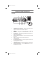
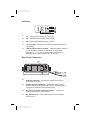
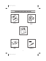
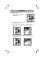
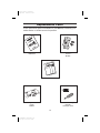
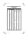
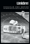
Color profile: Disabled
Composite Default screen
®
MC535
VHF Marine Radio
Operating Guide
C:\MANUALS7\mc535\Mc535.vp
Tue Sep 08 10:53:55 1998
Color profile: Disabled
Composite Default screen
Maritime Radio Services Operation
You are required to comply with the Rules and Regulations set
forth by the Federal Communications Commission. A complete set
of FCC Marine Radio Rules may be purchased from the US
Government Printing Office by requesting “Volume IV of the FCC
Rules.” Some of the important rules follow:
•
You must obtain a Ship’s Station License by making
application to the FCC on FCC Form 506. A copy of this
form is included with your radio. An Interim Ship’s Station
License may be obtained by personal appearance at your
local FCC Field Office. The Ship’s Station License must
be posted at the station location.
•
A Restricted Radiotelephone Operator Permit (or higher
grade license) must also be obtained from the FCC in
order to legally operate your transmitter in international
waters. Application is to be made on FCC Form 753. An
interim permit is automatically granted upon submission of
your application.
•
You must keep a current copy of the appropriate FCC
Rules.
•
You must maintain a log book in which you record all calls
and full transmitter maintenance records.
•
Your transmitter must be verified to be in compliance with
current FCC requirements by an appropriately licensed
technician. This has been done at the factory for your
MC535. A signed Certificate of Compliance Card is
included with your radio and should be kept with your log
book.
•
You may not make transmitter tuning adjustments unless
you are the holder of a valid first or second class
commercial license issued by the FCC. Please request
the assistance of your Uniden Marine Dealer and your
nearest FCC Field Office if you need other than a Ship’s
Station License.
C:\MANUALS7\mc535\Mc535.vp
Tue Sep 08 10:53:57 1998
Color profile: Disabled
Composite Default screen
Controls and Indicators
Controls
1.
UP/DWN Channel Selectors − These controls are used to
select the desired communication channel.
2.
LED Panel − Indicators for Channel Number, 16, INT, 1W
and TX.
3.
SQ (Squelch) − Eliminates the background noise when no
signal is being received.
4.
Push-to-Talk (PTT) Switch − Press to transmit and release
to receive.
5.
CH16 − Controls access to instant Channel 16
communications.
6.
INT (USA/International) − Switches operation between US
and International Channels.
7.
1W/25W(TX Output) − Controls transmitter’s output power.
8.
VOL (On/Off/Volume) − Turns the MC535 power on or off
and adjusts the volume.
C:\MANUALS7\mc535\Mc535.vp
Tue Sep 08 10:53:58 1998
Color profile: Disabled
Composite Default screen
Indicators
9.
16 − Indicates that Channel 16 is selected.
10.
INT − Indicates International Channel Mode.
11.
1W − Indicates transmitted output is 1 Watt.
12.
TX (Transmit) − Indicates PTT switch is pressed and radio is
transmitting.
13.
LED Numerical Channel Display − Indicates Channel Number
in use. Weather Channels are displayed as single digits
(Example: 0, 1, 2, 3, etc.). Communication Channels are
displayed as two digits (Example: 01, 02, 03, etc.).
Rear Panel Connectors
14.
Antenna Connector − Connect the antenna here using a
PL259 type connector.
15.
Remote Speaker Connector − An external 4 ohm, 4 watt
speaker may be connected to this jack. The connecting wire
must use the included 3.5mm miniature plug.
16.
DC Power Cord with In-line Fuse Holder − Connect red
power lead to positive power source.
17.
DC Ground Cord − Connect black power lead to negative
power source.
C:\MANUALS7\mc535\Mc535.vp
Tue Sep 08 10:53:55 1998
Color profile: Disabled
Composite Default screen
Table of Contents
Controls and Indicators . . . . . . . . . . . . . . . . . Front Cover Foldout
Introduction . . . . . . . . . . . . . . . . . . . . . . . . . . . . . . . . . . . . . . . . . 2
Features. . . . . . . . . . . . . . . . . . . . . . . . . . . . . . . . . . . . . . . . . . 2
Included with your MC535 . . . . . . . . . . . . . . . . . . . . . . . . . . . . . . 3
Installation . . . . . . . . . . . . . . . . . . . . . . . . . . . . . . . . . . . . . . . . . . 4
Selecting a Location . . . . . . . . . . . . . . . . . . . . . . . . . . . . . . . . 4
Antenna Considerations . . . . . . . . . . . . . . . . . . . . . . . . . . . . . 4
Engine Noise Suppression . . . . . . . . . . . . . . . . . . . . . . . . . . . 5
Installing the MC535 . . . . . . . . . . . . . . . . . . . . . . . . . . . . . . . . 5
Operation . . . . . . . . . . . . . . . . . . . . . . . . . . . . . . . . . . . . . . . . . . . 6
Setting the Squelch . . . . . . . . . . . . . . . . . . . . . . . . . . . . . . . . . 6
Selecting a Channel. . . . . . . . . . . . . . . . . . . . . . . . . . . . . . . . . 7
Channel Auto Repeat . . . . . . . . . . . . . . . . . . . . . . . . . . . . . . . 7
Instant Channel 16 Communications . . . . . . . . . . . . . . . . . . . . 8
USA/INT Channels . . . . . . . . . . . . . . . . . . . . . . . . . . . . . . . . . 8
Transmitting . . . . . . . . . . . . . . . . . . . . . . . . . . . . . . . . . . . . . . . 9
Troubleshooting . . . . . . . . . . . . . . . . . . . . . . . . . . . . . . . . . . . . . 11
Care and Maintenance . . . . . . . . . . . . . . . . . . . . . . . . . . . . . . . . 12
Replacement Parts . . . . . . . . . . . . . . . . . . . . . . . . . . . . . . . . . . . 13
Service. . . . . . . . . . . . . . . . . . . . . . . . . . . . . . . . . . . . . . . . . . . . . 14
Specifications . . . . . . . . . . . . . . . . . . . . . . . . . . . . . . . . . . . . . . . 15
USA/INT Frequency Lists . . . . . . . . . . . . . . . . Rear Cover Foldout
1
C:\MANUALS7\mc535\Mc535.vp
Tue Sep 08 10:53:44 1998
Color profile: Disabled
Composite Default screen
Introduction
The Uniden MC535 VHF marine radio transceiver is designed to provide
you with years of trouble-free service. It’s rugged components and
materials are easily capable of withstanding the harsh marine
environment. The transceiver has a splashproof housing to protect the
electronics, and the unit may be mounted in several convenient locations
on-board your vessel using the universal mounting bracket.
You can be confident in your choice of radio equipment because the
MC535 offers Instant Channel 16 access, automatic transmitter time-out,
and complete coverage of the marine frequency band. It will meet your
communication needs by providing you with state-of-the-art radio
electronics that are easy to operate.
We are certain that you will enjoy your MC535. To ensure that you get
the most from its features, please read this operating guide carefully
before using the unit.
Features
•
•
•
•
•
•
•
•
•
•
Receives 90 Marine Channels
1W/25W Transmitter
Instant Channel 16 Button
5 Minute Transmitter Time-Out
USA/INT Frequency Capable
Receives 10 Weather Channels
Transmits 55 Marine Channels
External Speaker Jack
Splash Proof Chassis
Channel Auto Repeat
Specifications, Features, and availability of Optional Accessories are all
subject to change without prior notice.
2
C:\MANUALS7\mc535\Mc535.vp
Tue Sep 08 10:53:44 1998
Color profile: Disabled
Composite Default screen
Included with your MC535
Microphone Hanger and
Screws
MH635
MC535 Owners Manual
OMMC535
Other Printed Material
3.5mm Mini Plug
ESP635
and Spare Fuse
Mounting Bracket and
Knobs
MB635
3
C:\MANUALS7\mc535\Mc535.vp
Tue Sep 08 10:53:46 1998
Color profile: Disabled
Composite Default screen
Installation
Caution: The MC535 will operate only with nominal 12 volt negative
ground battery systems.
Selecting a Location
Before choosing a location for your new MC535, review these guidelines:
•
Carefully consider the unit’s electrical and mechanical mounting
requirements, as well as your accessability needs.
•
Select a location that allows free air flow around the heat sink in
the back of the radio.
•
Select a location that is free from spray and splash and doesn’t
expose your radio to direct sunlight.
•
Keep the battery leads as short as possible, and for best results
connect directly to the battery. If the supplied power lead isn’t
long enough to reach the battery, extensions should be made
with at least #10 AWG wire.
•
Choose a location for the radio and auxillary speaker (if
installed) that is away from the ship’s compass.
Antenna Considerations
Many different antennas are available for your radio. We recommend that
you consult your Uniden dealer in determining a suitable antenna for your
vessel and range requirements.
In general when choosing or installing your antenna, consider these
guidelines:
•
The range increases with a high-gain antenna placed as high as
possible above the water line.
•
The antenna should not have an excessively long coaxial feed
cable.
•
The antenna should be located away from metal objects.
4
C:\MANUALS7\mc535\Mc535.vp
Tue Sep 08 10:53:46 1998
Color profile: Disabled
Composite Default screen
Engine Noise Suppression
The MC535 has been designed to minimize ignition and alternator noise.
However, in some installations it may be necessary to take additional
steps to help eliminate noise interference. During installation, try to direct
the DC battery wires, the antenna lead, and accessory cables away from
the engine compartment or ignition and alternator wiring.
If the noise continues, it may be necessary to install a noise suppression
kit. Contact your Uniden dealer for more information.
Installing the MC535
After choosing a location, position the radio (with the bracket,
microphone, power cord, antenna cable, and external speaker lead, if
installed) to make sure it fits. Then follow these steps:
1.
Using the bracket as a template, mark the holes for the mounting
hardware.
2.
Drill the holes and mount the bracket with hardware appropriate for
the mounting surface.
3.
Connect the red power lead
to the positive (+) battery
terminal or to an accessory
contact in your vessel’s fuse
box.
Note:The power cord is equipped
with a 6-ampere fast blow fuse to
protect your radio. Use only a
6-ampere replacement fuse.
4.
Connect the black wire of the power cord to the negative (–)
battery terminal or to a ground source in your vessel’s fuse box.
5.
Install the radio in the mounting bracket and connect the antenna
cable and accessories to their appropriate jacks and connectors.
5
C:\MANUALS7\mc535\Mc535.vp
Tue Sep 08 10:53:47 1998
Color profile: Disabled
Composite Default screen
Operation
Setting the Squelch
1.
To turn the unit ON, rotate VOLUME
clockwise. Adjust volume to a
comfortable level.
Note: You must select a channel which is not in use before setting the
SQUELCH control on your radio.
2.
Think of the Squelch control as a gate. If you turn SQUELCH fully
clockwise it raises the “Squelch Gate” so high that no signals get
through.
SQ
VOL
OFF
3.
If you turn SQUELCH fully counterclockwise it lowers the “Squelch
Gate” so that everything gets through — noise, weak signals, and
strong signals.
SQ
VOL
OFF
6
C:\MANUALS7\mc535\Mc535.vp
Tue Sep 08 10:53:48 1998
Color profile: Disabled
Composite Default screen
4.
To set the “Squelch Gate” to the desired level, turn SQUELCH
counterclockwise until you hear noise. Then turn SQUELCH back
clockwise just until the noise stops. Now only strong signals get
through.
Selecting a Channel
1.
2a.
When you turn on your MC535, it is
automatically on Channel 16.
Press UP, to select a higher channel,
— or —
2b.
Press DWN, to select a lower
channel.
Note: Each time UP or DWN is pressed a short tone sounds.
Channel Auto Repeat
To quickly change channels, press and hold UP or DWN. This changes
channels at five per second.
Note: A short tone sounds when you press either UP or DWN and the
channel changes. Another tone sounds when Channel Auto
Repeat begins.
7
C:\MANUALS7\mc535\Mc535.vp
Tue Sep 08 10:53:50 1998
Color profile: Disabled
Composite Default screen
Instant Channel 16 Communications
You can access Channel 16 instantly while tuned to another channel
using the CH16 switch.
1.
For example, suppose you are on
Channel 63.
2.
Press CH16.
3.
Press CH16 again, to return to the
previous channel.
Note: Each time CH16 is pressed a short tone sounds.
USA/INT Channels
The MC535 can transmit and receive in both USA and International
frequencies. To change the selected set of frequencies use INT.
1.
When you turn the MC535 on, the
USA frequencies are automatically
selected.
2.
Press INT, to change to the
international frequencies.
3.
Press INT again, to return to the
USA frequencies.
Note: Each time INT is pressed a short tone sounds.
8
C:\MANUALS7\mc535\Mc535.vp
Tue Sep 08 10:53:51 1998
Color profile: Disabled
Composite Default screen
Transmitting
The MC535 transmits on 55 marine frequencies and receives 90 different
marine frequencies. Certain channels — the weather channels, channel
70 of both the USA and International frequencies, and channel 15 of the
USA frequencies — are receive only. Your radio will not transmit on these
channels. For your reference, a listing of all the available marine
channels is printed on the back cover foldout.
Setting TX Output
Caution: It is important to remember to always use the 1W position in
port or for short range communications.
1.
When you turn the MC535 on, the unit
is automatically set to transmit at 25
watts.
2.
Press 1W/25W, to change the
transmitter output to 1W.
3.
Press 1W/25W again, to change back
to the higher power setting.
Note: Each time the 1W/25W key is pressed a short tone sounds.
Emergency High Power Override
The FCC has limited transmission power to 1W on channels 13 and 67,
except in emergencies. These channels are set automatically to 1W
when selected.
For example, you are on Channel 13.
9
C:\MANUALS7\mc535\Mc535.vp
Tue Sep 08 10:53:52 1998
Color profile: Disabled
Composite Default screen
If necessary, you can override the 1W power output setting during an
emergency situation.
Warning: This is an emergency procedure and should be used
accordingly.
1.
Press the PTT switch on your
microphone.
2.
Press and hold 1W/25W.
3.
Releasing the 1W/25W returns to
1W output.
Transmitting with the MC535
1.
Press the PTT switch, to activate the
transmitter.
2.
Release the PTT switch, to end the
transmission.
Note: If the PTT switch is held down and the power is turned on, a
warning tone sounds, the LED display begins to flash, and the
unit will not transmit. The MC535 resets for normal operation
when the PTT switch is released.
Transmitter Time-Out
If the PTT switch on your microphone is held for more than 5-minutes, the
MC535 transmitter automatically shuts off, a warning tone sounds, and
the LED display begins to flash. This prevents damage to your receiver,
and — in the event that the transmission is unintentional —
communication frequencies will not be jammed.
10
C:\MANUALS7\mc535\Mc535.vp
Tue Sep 08 10:53:53 1998
Color profile: Disabled
Composite Default screen
Troubleshooting
If your MC535 does not perform up to expectations, try the suggestions
listed below. If you cannot get satisfactory results, call the Uniden
Customer Service Center at (800) 586-0409, 8:00 a.m. to 5:00 p.m.,
Eastern Standard Time, Monday through Friday.
Unit does not
operate
Weak signal
Unit will not transmit
Excessive
background noise
Channel transmits
at 1W only
Channel display
flashes
• Make sure that the volume control is in the ON
position.
• Check in-line power fuse. Replace if
necessary with 6 amp fast-blow fuse only.
• Check the power cord. Be sure that the
connections are intact and 12V power is
supplied.
• Check antenna connections at base of
antenna and at the back of the radio.
• Change to another channel and check
reception again.
• Check to see if channel is “receive only.”
• Check antenna connections at base of
antenna and at the back of the radio.
• Check and set SQUELCH control.
• Check if FCC restricted channel. (See page 9
for more information).
• Turn power off. Release the PTT switch, and
turn the radio back on.
• Transmitter time-out activated. Release PTT
and allow radio to reset.
11
C:\MANUALS7\mc535\Mc535.vp
Tue Sep 08 10:53:53 1998
Color profile: Disabled
Composite Default screen
Care and Maintenance
Your MC535 is a precision piece of electronic equipment and you should
treat it accordingly. Its rugged design requires very little maintenance;
however, these precautions should be observed:
•
If your radio has been accidentally sprayed or splashed, you
should immediately wipe it down with a soft cloth dampened with
fresh water.
•
If the antenna has been damaged, you should not transmit
except in case of emergency. A defective antenna may cause
damage to your radio.
Since you are responsible for the continued FCC technical compliance of
your radio, we recommend that you arrange for periodic performance
checks with your Uniden Marine Dealer.
12
C:\MANUALS7\mc535\Mc535.vp
Tue Sep 08 10:53:53 1998
Color profile: Disabled
Composite Default screen
Replacement Parts
These replacement parts are available for your MC535 by contacting your
Uniden dealer or Uniden America Corporation.
Owners Manual
OMMC535
Microphone Hanger and
Screws
MH635
Other Printed Material
3.5mm Mini Plug
ESP635
and Spare Fuse
Mounting Bracket and
Knobs
MB635
13
C:\MANUALS7\mc535\Mc535.vp
Tue Sep 08 10:53:53 1998
Color profile: Disabled
Composite Default screen
Service
Should you find it desirable or necessary to service your MC535, we
suggest you contact the Uniden dealer where your purchase was made.
Your dealer will be able to assist you with complete service information.
If you require service that is within the terms of your warranty you should
present a copy of your receipt to your dealer to authenticate your claim.
If you find it inconvenient to obtain service assistance from a dealer, you
may obtain service from the Factory Service Station. If you want factory
service, please pack your radio in a suitable container that will provide
adequate protection, enclose a note describing the problem and a copy of
your receipt, and send the radio (transportation prepaid) to:
Uniden America Corporation
4700 Amon Carter Blvd.
Ft. Worth, TX 76155
(800) 297-1023, 8 AM to 5 PM Central, Monday through Friday
14
C:\MANUALS7\mc535\Mc535.vp
Tue Sep 08 10:53:53 1998
Color profile: Disabled
Composite Default screen
Specifications
General
Channels
Controls
Status Indicators
Channel Display
Channel Selector
Buttons
Connectors
Size
Weight
Supply Voltage
Antenna Impedance
Microphone
Speaker
Operating Temperature Range
Shock and Vibration
FCC Approvals
Transmitter
Power Output
Power Requirement
Modulation
Signal-to-Noise
Audio Distortion
Spurious Supression
Output Power Stabilization
Frequency Range
Frequency Stability:
Receiver
Frequency Range
Sensitivity
Circuit
Squelch Sensitivity
Spurious Response
Adjacent Channel Selectivity
Audio Output Power
Power Requirement
Transmit
Receive
55
80 Marine
10 Weather
ON/OFF/Volume, Squelch
16, INT, 1W,TX LED (transmit)
LED (Dual 7 segment)
UP/DWN select keys
CH16, INT, 1W/25W
Antenna and remote speaker
2 3/16“H x 6 1/8”W x 7 9/16“L
2.4 lbs
13.8V DC negative ground
50Ω, nominal
500Ω dynamic element with coiled cord
1.82 inch, 8Ω
-20°C to +50°C (-4°F to +122°F)
Meets or exceeds EIA standards, RS152B and
RS204C
Type accepted under part 80 of the Rules; meets
Great Lakes Agreement and party boat
requirements
1 watt or 25 watt (switch selectable)
1 watt output:
1.0A at 13.8V DC
25 watts output: 4.5A at 13.8V DC
FM ±5 kHz deviation (FCC designator F3E)
45 dB at 3 kHZ
Less than 5% with 3 kHz deviation with 1000 Hz
modulating frequency
-60 dB at 1 watt, -65 dB at 25 watts
Built-in automatic level control (ALC)
156 to 158 MHz
±300 Hz nominal
156 to 163 MHz
0.25µV for 12 dB SINAD
0.35µV for 20 dB S/N
Dual Conversion Super Heterodyne PLL
0.2µv Threshold
60 dB
70 dB at ±25 kHz
4.0 watts (10% Distortion) into a 4 Ω load
0.3A at 13.8V DC squelched
0.8A at 13.8V DC at maximum audio output
1st - 16.9 MHz
2nd - 455 kHz
15
C:\MANUALS7\mc535\Mc535.vp
Tue Sep 08 10:53:54 1998
Color profile: Disabled
Composite Default screen
VHF FM Marine Radiotelephone
Channels and Functions
(International Channels)
CHANNEL
DESIGN
WXO
WX1
WX2
WX3
WX4
WX5
WX6
WX7
WX8
WX9
01
02
03
04
05
06
07
08
09
10
11
12
13
14
15
16
17
18
19
20
21
22
23
24
25
26
27
28
60
61
62
63
64
65
66
67
68
69
70
71
72
73
74
77
78
79
80
81
82
83
84
85
86
87
88
FREQUENCY (MHz)
TRANSMIT
RECEIVE
—
—
—
—
—
—
—
—
—
—
156.050
156.100
156.150
156.200
156.250
156.300
156.350
156.400
156.450
156.500
156.550
156.600
156.650
156.700
156.750
156.800
156.850
156.900
156.950
157.000
157.050
157.100
157.150
157.200
157.250
157.300
157.350
157.400
156.025
156.075
156.125
156.175
156.225
156.275
156.325
156.375
156.425
156.475
—
156.575
156.625
156.675
156.725
156.875
156.925
156.975
157.025
157.075
157.125
157.175
157.225
157.275
157.325
157.375
157.425
C:\MANUALS7\mc535\Mc535.vp
Tue Sep 08 10:53:57 1998
163.275
162.550
162.400
162.475
162.425
162.450
162.500
162.525
161.650
161.775
160.650
160.700
160.750
160.800
160.850
156.300
160.950
156.400
156.450
156.500
156.550
156.600
156.650
156.700
156.750
156.800
156.850
161.500
161.550
161.600
161.650
161.700
161.750
161.800
161.850
161.900
161.950
162.000
160.625
160.675
160.725
160.775
160.825
160.875
160.925
156.375
156.425
156.475
156.525
156.575
156.625
156.675
156.725
156.875
161.525
161.575
161.625
161.675
161.725
161.775
161.825
161.875
161.925
161.975
162.025
TYPE OF
TRAFFIC
SHIP
TO SHIP
SHIP
TO SHORE
NOAA Weather
NOAA Weather
NOAA Weather
NOAA Weather
NOAA Weather
NOAA Weather
NOAA Weather
NOAA Weather
Can. Weather
Can. Weather
VTS
Port Ops
Port Ops
Port Ops
VTS
Safety
Com’l
Com’l
Com’l & Non Com’l
Com’l
Com’l
Port Ops
Navigational
Port Ops
Environmental
Safety Calling
State Control
Com’l
Com’l
Port Ops
Coast Guard
Coast Guard
Coast Guard
Public Corresp
Public Corresp
Public Corresp
Public Corresp
Public Corresp
RX Only
RX Only
RX Only
RX Only
RX Only
RX Only
RX Only
RX Only
RX Only
RX Only
Yes
Yes
Yes
Yes
Yes
Yes
Yes
Yes
Yes
Yes
Yes
Yes
Yes
Yes
Yes
Yes
Yes
Yes
Yes
Yes
Yes
Yes
Yes
No
No
No
No
No
RX Only
RX Only
RX Only
RX Only
RX Only
RX Only
RX Only
RX Only
RX Only
RX Only
Yes
Yes
Yes
Yes
Yes
No
Yes
No
Yes
Yes
Yes
Yes
Yes
Yes
Yes
Yes
Yes
Yes
Yes
Yes
Yes
Yes
Yes
Yes
Yes
Yes
Yes
Yes
Port Ops
Port Ops
Com’l
Non Com’l
Non Com’l
DSC
Non Com’l
Non Com’l
Port Ops
Port Ops
Port Ops
Non Com’l
Com’l
Com’l
Coast Guard
US Govt Only
Coast Guard
Public Corresp
Public Corresp
Public Corresp
Public Corresp
Com’l
Yes
Yes
Yes
Yes
Yes
No
Yes
Yes
Yes
Yes
Yes
Yes
Yes
Yes
Yes
Yes
Yes
No
No
No
No
Yes
Yes
Yes
No
Yes
Yes
No
Yes
No
Yes
Yes
No
Yes
Yes
Yes
Yes
Yes
Yes
Yes
Yes
Yes
Yes
No
Color profile: Disabled
Composite Default screen
VHF FM Marine Radiotelephone
Channels and Functions
(U.S.A. Channels)
CHANNEL
DESIGN
FREQUENCY (MHz)
TRANSMIT
RECEIVE
WX0
WX1
WX2
WX3
WX4
WX5
WX6
WX7
WX8
WX9
01
02
03
04
05
06
07
08
09
10
11
12
13
14
15
16
17
18
19
20
21
22
23
24
25
26
27
28
60
61
62
63
64
65
66
67
68
69
70
71
72
73
74
77
78
79
80
81
82
83
84
85
86
87
88
—
—
—
—
—
—
—
—
—
—
156.050
156.100
156.150
156.200
156.250
156.300
156.350
156.400
156.450
156.500
156.550
156.600
156.650
156.700
—
156.800
156.850
156.900
156.950
157.000
157.050
157.100
157.150
157.200
157.250
157.300
157.350
157.400
156.025
156.075
156.125
156.175
156.225
156.275
156.325
156.375
156.425
156.475
—
156.575
156.625
156.675
156.725
156.875
156.925
156.975
157.025
—
157.125
—
157.225
157.275
157.325
157.375
157.425
C:\MANUALS7\mc535\Mc535.vp
Tue Sep 08 10:53:59 1998
163.275
162.550
162.400
162.475
162.425
162.450
162.500
162.525
161.650
161.775
156.050
156.100
156.150
156.200
156.250
156.300
156.350
156.400
156.450
156.500
156.550
156.600
156.650
156.700
156.750
156.800
156.850
156.900
156.950
161.600
157.050
157.100
157.150
161.800
161.850
161.900
161.950
162.000
156.025
156.075
156.125
156.175
156.225
156.275
156.325
156.375
156.425
156.475
156.525
156.575
156.625
156.675
156.725
156.875
156.925
156.975
157.025
157.075
157.125
157.175
161.825
161.875
161.925
161.975
157.425
TYPE OF
TRAFFIC
SHIP
TO SHIP
SHIP
TO SHORE
NOAA Weather
NOAA Weather
NOAA Weather
NOAA Weather
NOAA Weather
NOAA Weather
NOAA Weather
NOAA Weather
Can. Weather
Can. Weather
VTS
Port Ops
Port Ops
Port Ops
VTS
Safety
Com’l
Com’l
Com’l & Non Com’l
Com’l
Com’l
Port Ops
Navigational
Port Ops
Environmental
Safety Calling
State Control
Com’l
Com’l
Port Ops
Coast Guard
Coast Guard
Coast Guard
Public Corresp
Public Corresp
Public Corresp
Public Corresp
Public Corresp
RX Only
RX Only
RX Only
RX Only
RX Only
RX Only
RX Only
RX Only
RX Only
RX Only
Yes
Yes
Yes
Yes
Yes
Yes
Yes
Yes
Yes
Yes
Yes
Yes
Yes
Yes
RX Only
Yes
Yes
Yes
Yes
Yes
Yes
Yes
Yes
No
No
No
No
No
RX Only
RX Only
RX Only
RX Only
RX Only
RX Only
RX Only
RX Only
RX Only
RX Only
Yes
Yes
Yes
Yes
Yes
No
Yes
No
Yes
Yes
Yes
Yes
Yes
Yes
RX Only
Yes
Yes
Yes
Yes
Yes
Yes
Yes
Yes
Yes
Yes
Yes
Yes
Yes
Port Ops
Port Ops
Com’l
Non Com’l
Non Com’l
DSC
Non Com’l
Non Com’l
Port Ops
Port Ops
Port Ops
Non Com’l
Com’l
Com’l
Coast Guard Aux
US Govt Only
Coast Guard Aux
Public Corresp
Public Corresp
Public Corresp
Public Corresp
Com’l
Yes
Yes
Yes
Yes
Yes
No
Yes
Yes
Yes
Yes
Yes
Yes
Yes
Yes
No
Yes
No
No
No
No
No
Yes
Yes
Yes
No
Yes
Yes
No
Yes
No
Yes
Yes
No
Yes
Yes
Yes
No
Yes
No
Yes
Yes
Yes
Yes
No
Color profile: Disabled
Composite Default screen
One Year Limited Warranty
WARRANTOR: UNIDEN AMERICA CORPORATION (“Uniden”)
ELEMENTS OF WARRANTY: Uniden warrants, for one year, to the
original retail owner, this Uniden Product to be free from defects in
materials and craftsmanship with only the limitations or exclusions set out
below.
WARRANTY DURATION: This warranty to the original user shall
terminate and be of no further effect 12 months after the date of original
retail sale. The warranty is invalid if the Product is (A) damaged or not
maintained as reasonable or necessary, (B) modified, altered, or used as
part of any conversion kits, subassemblies, or any configurations not sold
by Uniden, (C) improperly installed, (D) serviced or repaired by someone
other than an authorized Uniden service center for a defect or malfunction
covered by this warranty, (E) used in any conjunction with equipment or
parts or as part of any system not manufactured by Uniden, or (F) installed
or programmed by anyone other than as detailed by the Operating Guide
for this product.
STATEMENT OF REMEDY: In the event that the product does not
conform to this warranty at any time while this warranty is in effect,
warrantor will repair the defect and return it to you without charge for parts,
service, or any other cost (except shipping and handling) incurred by
warrantor or its representatives in connection with the performance of this
warranty. THE LIMITED WARRANTY SET FORTH ABOVE IS THE SOLE
AND ENTIRE WARRANTY PERTAINING TO THE PRODUCT AND IS IN
LIEU OF AND EXCLUDES ALL OTHER WARRANTIES OF ANY
NATURE WHATSOEVER, WHETHER EXPRESS, IMPLIED OR ARISING
BY OPERATION OF LAW, INCLUDING, BUT NOT LIMITED TO ANY
IMPLIED WARRANTIES OF MERCHANTABILITY OR FITNESS FOR A
PARTICULAR PURPOSE. THIS WARRANTY DOES NOT COVER OR
PROVIDE FOR THE REIMBURSEMENT OR PAYMENT OF INCIDENTAL
OR CONSEQUENTIAL DAMAGES. Some states do not allow this
exclusion or limitation of incidental or consequential damages so the
above limitation or exclusion may not apply to you.
LEGAL REMEDIES: This warranty gives you specific legal rights, and you
may also have other rights which vary from state to state. This warranty is
void outside the United States of America.
PROCEDURE FOR OBTAINING PERFORMANCE OF WARRANTY: If,
after following the instructions in this Operating Guide you are certain that
the Product is defective, pack the Product carefully (preferably in its
original packaging). Include evidence of original purchase and a note
describing the defect that has caused you to return it. The Product should
be shipped freight prepaid, by traceable means, or delivered, to warrantor
at:
Uniden America Corporation
Parts and Service Division
4700 Amon Carter Blvd.
Ft. Worth, TX 76155
(800) 297-1023, 8 AM to 5 PM Central, Monday through Friday
C:\MANUALS7\mc535\Mc535.vp
Tue Sep 08 10:53:58 1998
Color profile: Disabled
Composite Default screen
®
©1995 Uniden America Corporation. All rights reserved.
UTZZ01860ZZ
C:\MANUALS7\mc535\Mc535.vp
Tue Sep 08 10:53:57 1998
Printed in the Philippines