1
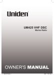
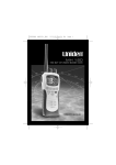
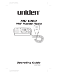
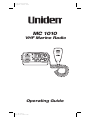
Color profile: Disabled
Composite Default screen
MC 1010
VHF Marine Radio
Operating Guide
C:...MC 1010.vp
Thu Jan 28 14:42:49 1999
Color profile: Disabled
Composite Default screen
Maritime Radio Services Operation
Warning!
This transmitter will operate on channels/ frequencies that
have restricted use in the United States. The channel
assignments include frequencies assigned for exclusive use
of the U.S. Coast Guard, use in Canada, and use in
international waters. Operation in these frequencies without
proper authorization is strictly forbidden. For
frequencies/channels that are currently for use in the U.S.
without an individual license, please contact the FCC Call
Center at 1-888-CALL-FCC.
For individuals requiring a license, such as commercial users, you should
obtain a license application from your nearest FCC field office.
C:...MC 1010.vp
Thu Jan 28 14:42:50 1999
Color profile: Disabled
Composite Default screen
CONTENTS
Uniden MC 1010. . . . . . . . . . . . . . . . . . . . . . . . . . . . . . . . . . . . . . . . . . . . . . . 1
Installation . . . . . . . . . . . . . . . . . . . . . . . . . . . . . . . . . . . . . . . . . . . . . . . . . . . 2
Choosing a Location . . . . . . . . . . . . . . . . . . . . . . . . . . . . . . . . . . . . . . . . 2
Engine Noise Suppression. . . . . . . . . . . . . . . . . . . . . . . . . . . . . . . . . . . . 3
Antenna Considerations. . . . . . . . . . . . . . . . . . . . . . . . . . . . . . . . . . . . . . 3
Installing TheMC 1010 . . . . . . . . . . . . . . . . . . . . . . . . . . . . . . . . . . . . . . . 3
Controls and Indicators. . . . . . . . . . . . . . . . . . . . . . . . . . . . . . . . . . . . . . . . . . 4
Front Panel . . . . . . . . . . . . . . . . . . . . . . . . . . . . . . . . . . . . . . . . . . . . . . . 4
Rear Panel Connectors . . . . . . . . . . . . . . . . . . . . . . . . . . . . . . . . . . . . . . 5
Multi-Function Keys . . . . . . . . . . . . . . . . . . . . . . . . . . . . . . . . . . . . . . . . . 7
Operation . . . . . . . . . . . . . . . . . . . . . . . . . . . . . . . . . . . . . . . . . . . . . . . . . . . . 8
Manual Tuning . . . . . . . . . . . . . . . . . . . . . . . . . . . . . . . . . . . . . . . . . . . . . 8
Instant Channel 16/Channel 9 Communications . . . . . . . . . . . . . . . . . . . 8
Triple Watch . . . . . . . . . . . . . . . . . . . . . . . . . . . . . . . . . . . . . . . . . . . . . . . 8
Weather Scan . . . . . . . . . . . . . . . . . . . . . . . . . . . . . . . . . . . . . . . . . . . . . 9
MEM (Entering channels into Memory) . . . . . . . . . . . . . . . . . . . . . . . . . . 9
Scanning Channels in Memory . . . . . . . . . . . . . . . . . . . . . . . . . . . . . . . . 9
Transmitting . . . . . . . . . . . . . . . . . . . . . . . . . . . . . . . . . . . . . . . . . . . . . . 10
Optional Accessories . . . . . . . . . . . . . . . . . . . . . . . . . . . . . . . . . . . . . . . 11
VHF FM Marine RadioTelephone
Channel and Functions
(USA Channels) . . . . . . . . . . . . . . . . . . . . . . . . . . . . . . . . . . . . . . . . . . . . . . 12
VHF FM Marine RadioTelephone
Channel and Functions
(International Channels) . . . . . . . . . . . . . . . . . . . . . . . . . . . . . . . . . . . . . . . . 13
VHF FM Marine RadioTelephone
Channel and Functions
(Canadian Channels) . . . . . . . . . . . . . . . . . . . . . . . . . . . . . . . . . . . . . . . . . . 14
Specifications . . . . . . . . . . . . . . . . . . . . . . . . . . . . . . . . . . . . . . . . . . . . . . . . 15
C:...MC 1010.vp
Thu Jan 28 14:42:50 1999
Color profile: Disabled
Composite Default screen
Uniden MC 1010
The Uniden MC 1010 VHF marine radio transceiver has been designed to
give you a rugged, reliable instrument that will provide you with years of
trouble-free service.
The technical excellence of the Uniden MC 1010 is demonstrated by the
many of uses for which it has been found acceptable by the U.S. Federal
Communications Commission. The Uniden MC 1010 is acceptable for
compulsory use on “party boats,” for use on vessels subject to the Great
Lakes Radio Agreement or bridge-to-bridge requirements, for general pleasure
and commercial vessels, and certain land stations in marine service.
The Uniden MC 1010 is of all solid state design with conservatively rated
rugged components and materials compatible with the marine environment.
The transceiver utilizes a number of gaskets, sealing rings, waterproof
membranes, and other sealants to effect a splashproof housing for protection
of the electronics. The unit may be mounted in any number of convenient
locations on your vessel by utilizing the universal mounting bracket.
You are encouraged to read the rest of this Operating Guide thoroughly to
acquaint yourself with the characteristics and operation of your transceiver so
that you can contribute to the longevity of your investment.
Be sure to complete the Product Registration Card at the back of this Guide,
cut it out and mail it.
Keep your receipt as proof-of-purchase in case warranty service is required.
Features, Specifications, and availability of Optional Accessories are all
subject to change without notice.
1
C:...MC 1010.vp
Thu Jan 28 14:42:51 1999
Color profile: Disabled
Composite Default screen
Installation
Caution:
The MC 1010 will operate only with nominal 12 volt
negative ground battery systems.
It is important to determine carefully the most suitable location for your MC
1010 on your vessel. Electrical, mechanical, and environmental considerations
must all be taken into account. You must select the optimum relationship
among these considerations.
Keep in mind the flexibility designed into the MC 1010 so that you can most
conveniently use your radio. Features which should be considered are:
1.
The universal mounting bracket may be installed on either the top or
bottom of a shelf, on a bulkhead, or for overhead mounting.
2.
The REMOTE speaker jack can be used with an auxiliary speaker.
3.
All connections are “plug-in” type for easy removal of the radio.
4.
Front fire internal speaker allows convenient in-dash mounting using the
optional bracket.
Choosing a Location
Some important factors to consider in selecting the location for your MC 1010:
1.
Select a location that is free from spray and splash.
2.
Keep the battery leads as short as possible. Direct connection to the
battery is most desirable. If direct connection cannot be made with the
supplied power lead, any extension should be made with #10 AWG wire.
Long extensions should use larger gauge wire.
3.
Keep the antenna lead as short as possible. Long antenna leads can cause
substantial loss of performance for both receiving and transmitting.
4.
Locate your antenna as high as possible and clear from metal objects. The
reliable range of coverage is a direct function of antenna height.
5.
Select a location that does not allow the radio to be subjected to direct
sunlight (including that coming through windows).
6.
Select a location that allows free air flow around the heat sink on the rear
of the radio.
7.
Select a location well away from the ship’s compass. Auxiliary speakers
also should be located away from the compass.
2
C:...MC 1010.vp
Thu Jan 28 14:42:51 1999
Color profile: Disabled
Composite Default screen
Engine Noise Suppression
Interference from the impulse noise generated by the electrical systems of
engines is sometimes a problem with radios. The MC 1010 has been designed
to be essentially impervious to ignition impulse noise and alternator noise.
However, in some installations it may be necessary to take measures to
further reduce the effect of noise interference. All DC battery wires, antenna
lead, and accessory cables should be routed away from the engine and
engine compartment, and from power cabling carrying particularly high
currents.
In severe cases of impulse noise interference, it may be necessary to install a noise
suppression kit. Contact Uniden for more information.
Antenna Considerations
A variety of antennas is available from a number of quality suppliers. It is
recommended you draw upon the advice of Uniden in determining a suitable
antenna for your vessel and range requirements.
In general, communication range is increased by using a high-gain antenna
placed as high as possible above the water line. Antennas should be located
away from metal objects. Antennas should not have excessively long coaxial
feed cables.
Installing The MC 1010
After you have carefully considered the various factors affecting your choice of
location, position the radio (with the bracket, microphone, power cord, antenna
and any auxiliary cables installed) into the selected location to assure there is
no interference with the surrounding items. Mark the location of the mounting
bracket. Remove the bracket from the radio and use it as a template to mark
the holes to be drilled for the mounting hardware. Drill the holes and mount the
bracket with hardware compatible with the material of the mounting surface.
Connect the red wire of the supplied power cord to the positive (+) battery
supply. Connect the black wire of the power cord to ground. The power cord is
equipped with a fuse to protect the radio. Use only a Six (6) Ampere fast blow
fuse for replacement. Connect the power cord to the keyed connector on the
power “pigtail” (See page 9).
Connect the antenna and all other auxiliary cables and accessories.
Install the radio in the mounting bracket and connect all cables and
accessories to the appropriate jacks and connectors.
3
C:...MC 1010.vp
Thu Jan 28 14:42:51 1999
Color profile: Disabled
Composite Default screen
Controls and Indicators
Front Panel
8
9
1
7 6 5 4 3
2
1.
VOLUME (On/Off/Volume) - Turns the MC 1010 On or Off and varies the
audio output.
2.
SQUELCH - Eliminates background noise when no signal is being
received.
Note:
Items 3 through 7 are Multi-Function keys. Refer to the
“Multi-Function Keys” section for detailed descriptions.
3.
STEP
4.
H/L (Hi/Low)
5.
MEM
6.
16/9
7.
WX (Weather)
8.
CHAN - This control is used to manually select the desired
Communication Channel (01 - 28 and 60 - 88), or Weather Channel
(0 - 9).
9.
LCD Panel - Indicators for TX, SCAN, TRI, U I C, HI, LO, MEM, WX, and
Channel Number.
4
C:...MC 1010.vp
Thu Jan 28 14:42:51 1999
Color profile: Disabled
Composite Default screen
Rear Panel Connectors
12
11
10
10. DC Power - The “Pigtail” cord and connector are power in.
11. Remote Speaker Connector - An external 4 ohm, 4 Watt speaker may be
connected to this jack. The connecting wire must have a miniature plug.
12. Antenna Connector - Connect the antenna here using a type PL259
connector.
Supplied Power Cord - Connect supplied power cord to the keyed
connector.
5
C:...MC 1010.vp
Thu Jan 28 14:42:52 1999
Color profile: Disabled
Composite Default screen
13. LCD Numerical Channel Display - Indicates Channel Number in use.
Weather Channels are displayed as single digits. (Example: 0, 1, 2, 3,
etc.) Communication Channels are displayed as two digits (Example: 01,
02, 03, etc.).
Note:
LCD Status Indicators appear when status is selected by
pressing the corresponding button.
14. WX - Indicates that Weather Channels have been selected. When
pressed, remains active for eight (8) seconds.
15. U (US) - Indicates US Channels have been selected.
I (International) - Indicates International Channels have been selected.
C (Canada) - Indicates Canada Channels have been selected.
16. TRI (Triple Watch) - Indicates Triple Watch s has been selected.
17. SCAN - Indicates that you are scanning the channels in memory.
18. TX (Transmit) - LED lights when transmitting.
19. HI (High) - Indicates transmitted output is 25 Watts.
20. LO (Low) - Indicates transmitted output is 1 Watt.
21. MEM (Memory) - Indicates if the displayed channel is in memory for
scanning.
6
C:...MC 1010.vp
Thu Jan 28 14:42:52 1999
Color profile: Disabled
Composite Default screen
Multi-Function Keys
3.
STEP - This key is used to step through the channels which are stored in
memory. When pressed and held, this key also starts and stops the
SCAN Mode.
• Press STEP to step through the channels which are stored in
memory.
• Press and hold STEP to begin scanning the channels in memory.
Note: Triple Watch is automatically activated when scanning
begins.
4.
H/L - This key allows you to switch between high transmit power (25
watts) or low transmit power (1 Watt). Some channels may not allow high
power to be used.
5.
MEM - This key enters the displayed channel into memory.
6.
16/9 - This key allows rapid access to channels 16 and 9. On the first
press, the radio will select channel 16. On the next press the radio will
select channel 9. On the next press, the radio will return to the original
channel.
• Press16/9 to access instant Channel 16/Channel 9
communications.
• Press and hold 16/9 to turn Triple Watch On/Off.
7.
WX (Weather) - This key is used to switch between monitoring weather
channels and communication channels. This key is also used to select the
channel mode of operation.
• Press WX to switch between weather and communication
channels.
• Press and hold WX to select channel mode of operation.
7
C:...MC 1010.vp
Thu Jan 28 14:42:53 1999
Color profile: Disabled
Composite Default screen
Operation
1.
Turn the unit on by rotating the VOL control clockwise.
2.
Adjust the SQUELCH control counterclockwise until you hear background
noise, and then turn it clockwise until the noise just disappears.
Triple Watch
Triple Watch monitors Channel 16 and Channel 9 for activity every two
seconds while scanning or monitoring.
To activate Triple Watch, press and hold 16/9 until two short beeps occur.
The
indicator appears on the LCD panel, indicating Triple Watch mode is
in effect. If a signal is received on either Channel 16 or Channel 9, the radio
remains on that channel until the signal ends
Press and hold 16/9 until the tone sounds to cancel Triple Watch Mode.
Manual Tuning
To select a channel manually, press the CHAN selector buttons (up/down) to
select the desired channel. Weather channels are located on Channels 0 - 9.
Communication Channels are located on Channels 01 - 28 and 60 - 88.
Instant Channel 16/Channel 9 Communications
To access instant Channel 16 or Channel 9 communications, press 16/9. This
overrides the channel selected with the CHAN selector buttons or any
scanning activity. The Channel Display indicates the unit is on Channel 16.
Press 16/9 again to access Channel 9 communications. Press 16/9 a third
time to release the switch (Off). The transceiver will return to the channel
selected prior to accessing instant Channel 16/Channel 9 communications.
The Channel Display will indicate the selected channel.
8
C:...MC 1010.vp
Thu Jan 28 14:42:53 1999
Color profile: Disabled
Composite Default screen
To cancel Channel 16/Channel 9 communications:
• Press 16/9 until previous channel setting appears.
—or—
• Press WX.
Weather Scan
To scan only Weather Channels 0 - 9, press WX, and then press and hold
STEP. The
indicator will appear on the LCD Panel, indicating Weather
Mode.
To exit from Weather Scanning:
• Press 16/9 to change to Channel 16/Channel 9 communications
—or—
• Press WX to change to standard channel communications.
US/International/Canadian Channels
To select operation (communication and scanning) on US Channels, press
and hold WX to select the desired mode of operation. U (USA),
I (International), or C (Canadian) will appear on the LCD Panel.
Select the appropriate mode for operation.
MEM (Entering channels into Memory)
You can enter channels into memory for instant scanning at any time.When a
channel is selected for Memory Scan, the
indicator will appear on the
LCD display.
To enter a channel number into memory, select the channel number you want
stored by pressing the CHAN Selector button up or down, and then press MEM.
Note:
In order for all functions of theMC 1010 to work properly, at least
two channel numbers must be entered into the Memory Scan
before operating the radio.
Memory Scan
To scan channels stored in Memory Scan, press and hold STEP. In the
Memory Scan Mode, theMC 1010 scans only those channel numbers
previously entered into Memory Scan. If no channel has been entered into
Memory Scan, the error tone sounds and the LCD Panel does not change.
Note:
While in SCAN, pressing the 16/9 button three times or pressing
and holding STEP will return the radio to the last channel it was on
while in Scan mode.
9
C:...MC 1010.vp
Thu Jan 28 14:42:53 1999
Color profile: Disabled
Composite Default screen
Transmitting
When the power is turned on, the transmitter is set for 25 Watts (except for
USA Channels 13 and 67). The HI indicator will appear on the LCD Panel,
indicating 25 Watt transmit power. Channels 13 and 67 are restricted to 1
Watt. However, 25 Watt output for emergency use is available by pressing H/L
while pressing the Press-To-Talk switch. When the H/L switch is released, the
radio returns to the 1 Watt position.
One watt transmit power (LO) should be selected for most communications.
This prevents your signal from interfering with other vessels’ communications,
and will work fine unless maximum range is required. Press the H/L button
until LO is shown in the display.
Twenty-five watt transmit power (HI) provides greate range, and will allow your
signal to be heard over weaker signals. It should be used only when
necessary.
To activate the transmitter, press the Press-To-Talk switch on the microphone.
The
LED indicator will light, indicating a signal is being transmitted.
Release the switch to receive. When transmitting, hold the microphone
approximately two inches from your mouth and speak clearly in a normal
voice.
Note:
You cannot transmit on Weather Channels 0 - 9 or Channel
15. The Channel Number in the LCD Panel will blink to indicate
these channels are “receive-only”.
10
C:...MC 1010.vp
Thu Jan 28 14:42:54 1999
Color profile: Disabled
Composite Default screen
Optional Accessories
• Flush mounting bracket for “in dash” installation.
Contact Uniden for information.
11
C:...MC 1010.vp
Thu Jan 28 14:42:54 1999
Color profile: Disabled
Composite Default screen
VHF FM Marine RadioTelephone
Channel and Functions
(USA Channels)
CHANNEL FREQUENCY (MHz)
DESIG TRANSMIT RECEIVE
WX0
WX1
WX2
WX3
WX4
WX5
WX6
WX7
WX8
WX9
01
02
03
05
06
07
08
09
10
11
12
13
14
15
16
17
18
19
20
21
22
23
24
25
26
27
28
60
61
63
64
65
66
67
68
69
71
72
73
74
77
78
79
80
81
82
83
84
85
86
87
88
TYPE OF
TRAFFIC
SHIP
SHIP
TO SHIP TO SHORE
—
—
—
—
—
—
—
—
—
—
156.050
163.275
162.550
162.400
162.475
162.425
162.450
162.500
162.525
161.650
161.775
156.050
NOAA Weather
NOAA Weather
NOAA Weather
NOAA Weather
NOAA Weather
NOAA Weather
NOAA Weather
NOAA Weather
Can. Weather
Can. Weather
VTS
RX Only
RX Only
RX Only
RX Only
RX Only
RX Only
RX Only
RX Only
RX Only
RX Only
Yes
RX Only
RX Only
RX Only
RX Only
RX Only
RX Only
RX Only
RX Only
RX Only
RX Only
Yes
156.150
156.250
156.300
156.350
156.400
156.450
156.500
156.550
156.600
156.650
156.700
—
156.800
156.850
156.900
156.950
157.000
157.050
157.100
157.150
157.200
157.250
157.300
157.350
157.400
156.150
156.250
156.300
156.350
156.400
156.450
156.500
156.550
156.600
156.650
156.700
156.750
156.800
156.850
156.900
156.950
161.600
157.050
157.100
157.150
161.800
161.850
161.900
161.950
162.000
Port Ops
VTS
Safety
Com’l
Com’l
Com’l & Non Com’l
Com’l
Com’l
Port Ops
Navigational, TX 1W only
Port Ops
Environmental
Safety Calling
State Control
Com’l
Com’l
Port Ops, RX Duplex
Coast Guard
Coast Guard
Coast Guard
Public Corresp,Duplex
Public Corresp,Duplex
Public Corresp,Duplex
Public Corresp,Duplex
Public Corresp,Duplex
Yes
Yes
Yes
Yes
Yes
Yes
Yes
Yes
Yes
Yes
Yes
RX Only
Yes
Yes
Yes
Yes
Yes
Yes
Yes
Yes
No
No
No
No
No
Yes
Yes
No
Yes
No
Yes
Yes
Yes
Yes
Yes
Yes
RX Only
Yes
Yes
Yes
Yes,
Yes
Yes
Yes
Yes
Yes
Yes
Yes
Yes
Yes
156.075
156.175
156.225
156.275
156.325
156.375
156.425
156.475
156.575
156.625
156.675
156.725
156.875
156.925
156.975
157.025
157.075
157.125
157.175
157.225
157.275
157.325
157.375
157.425
156.075
156.175
156.225
156.275
156.325
156.375
156.425
156.475
156.575
156.625
156.675
156.725
156.875
156.925
156.975
157.025
157.075
161.725
157.175
161.825
161.875
161.925
161.975
157.425
Port Ops
Port Ops
Com’l, TX 1W only
Non Com’l
Non Com’l
Non Com’l
Non Com’l
Port Ops
Port Ops
Port Ops
Non Com’l
Com’l
Com’l
Coast Guard
US Govt Only
Coast Guard
Public Corresp,Duplex
Public Corresp,Duplex
Public Corresp,Duplex
Public Corresp,Duplex
Com’l
Yes
Yes
Yes
Yes
Yes
Yes
Yes
Yes
Yes
Yes
Yes
Yes
Yes
Yes
Yes
Yes
No
No
No
No
Yes
Yes
Yes
No
Yes
Yes
Yes
No
Yes
Yes
No
Yes
Yes
Yes
Yes
Yes
Yes
Yes
Yes
Yes
Yes
No
12
C:...MC 1010.vp
Thu Jan 28 14:42:55 1999
PERMANENT
SCAN LIST
Weather
Weather
Weather
Weather
Weather
Weather
Weather
Weather
Weather
Weather
Coast Guard
Fish
Environmental
Coast Guard
Coast Guard
Coast Guard
Busy Tel.
Busy Tel.
Busy Tel.
Busy Tel.
Busy Tel.
Fish
Fish
Fish
Fish
Fish
Coast Guard
Coast Guard
Busy Tel.
Busy Tel.
Busy Tel.
Busy Tel.
Color profile: Disabled
Composite Default screen
VHF FM Marine RadioTelephone
Channel and Functions
(International Channels)
CHANNEL FREQUENCY (MHz)
DESIG TRANSMIT RECEIVE
WXO
WX1
WX2
WX3
WX4
WX5
WX6
WX7
WX8
WX9
01
02
03
04
05
06
07
08
09
10
11
12
13
14
15
16
17
18
19
20
21
22
23
24
25
26
27
28
60
61
62
63
64
65
66
67
68
69
71
72
73
74
77
78
79
80
81
82
83
84
85
86
87
88
—
—
—
—
—
—
—
—
—
—
156.050
156.100
156.150
156.200
156.250
156.300
156.350
156.400
156.450
156.500
156.550
156.600
156.650
156.700
156.750
156.800
156.850
156.900
156.950
157.000
157.050
157.100
157.150
157.200
157.250
157.300
157.350
157.400
156.025
156.075
156.125
156.175
156.225
156.275
156.325
156.375
156.425
156.475
156.575
156.625
156.675
156.725
156.875
156.925
156.975
157.025
157.075
157.125
157.175
157.225
157.275
157.325
157.375
157.425
163.275
162.550
162.400
162.475
162.425
162.450
162.500
162.525
161.650
161.775
160.650
160.700
160.750
160.800
160.850
156.300
160.950
156.400
156.450
156.500
156.550
156.600
156.650
156.700
156.750
156.800
156.850
161.500
161.550
161.600
161.650
161.700
161.750
161.800
161.850
161.900
161.950
162.000
160.625
160.675
160.725
160.775
160.825
160.875
160.925
156.375
156.425
156.475
156.575
156.625
156.675
156.725
156.875
161.525
161.575
161.625
161.675
161.725
161.775
161.825
161.875
161.925
161.975
162.025
TYPE OF
TRAFFIC
NOAA Weather
NOAA Weather
NOAA Weather
NOAA Weather
NOAA Weather
NOAA Weather
NOAA Weather
NOAA Weather
Can. Weather
Can. Weather
VTS,Duplex
Port Ops,Duplex
Port Ops,Duplex
Port Ops,Duplex
VTS,Duplex
Safety
Com’,Duplexl
Com’l
Com’l & Non Com’l
Com’l
Com’l
Port Ops
Navigational
Port Ops
Environmental
Safety Calling
State Control
Com’l,Duplex
Com’l,Duplex
Port Ops,Duplex
Coast Guard,Duplex
Coast Guard,Duplex
Coast Guard,Duplex
Public Corresp,Duplex
Public Corresp,Duplex
Public Corresp,Duplex
Public Corresp,Duplex
Public Corresp,Duplex
Duplex
Duplex
Duplex
Duplex
Duplex
Port Ops,Duplex
Port Ops,Duplex
Com’l
Non Com’l
Non Com’l
Non Com’l
Non Com’l
Port Ops
Port Ops
Port Ops
Non Com’l,Duplex
Com’l,Duplex
Com’l,Duplex
Coast Guard,Duplex
US Govt Only,Duplex
Coast Guard,Duplex
Public Corresp,Duplex
Public Corresp,Duplex
Public Corresp,Duplex
Public Corresp,Duplex
Com’l,Duplex
13
C:...MC 1010.vp
Thu Jan 28 14:42:56 1999
SHIP
SHIP
TO SHIP TO SHORE
RX Only
RX Only
RX Only
RX Only
RX Only
RX Only
RX Only
RX Only
RX Only
RX Only
Yes
Yes
Yes
Yes
Yes
Yes
Yes
Yes
Yes
Yes
Yes
Yes
Yes
Yes
Yes
Yes
Yes
Yes
Yes
Yes
Yes
Yes
Yes
No
No
No
No
No
RX Only
RX Only
RX Only
RX Only
RX Only
RX Only
RX Only
RX Only
RX Only
RX Only
Yes
Yes
Yes
Yes
Yes
No
Yes
No
Yes
Yes
Yes
Yes
Yes
Yes
Yes
Yes
Yes
Yes
Yes
Yes
Yes
Yes
Yes
Yes
Yes
Yes
Yes
Yes
Yes
Yes
Yes
Yes
Yes
Yes
Yes
Yes
Yes
Yes
Yes
Yes
Yes
Yes
Yes
Yes
No
No
No
No
Yes
Yes
Yes
No
Yes
Yes
Yes
No
Yes
Yes
No
Yes
Yes
Yes
Yes
Yes
Yes
Yes
Yes
Yes
Yes
No
PERMANENT
SCAN LIST
Weather
Weather
Weather
Weather
Weather
Weather
Weather
Weather
Weather
Weather
Fish
Environmental
Busy Tel.
Busy Tel.
Busy Tel.
Busy Tel.
Busy Tel.
Fish
Fish
Fish
Fish
Coast Guard
Coast Guard
Busy Tel.
Busy Tel.
Busy Tel.
Busy Tel.
Busy Tel.
Color profile: Disabled
Composite Default screen
VHF FM Marine RadioTelephone
Channel and Functions
(Canadian Channels)
CHANNEL FREQUENCY (MHz)
DESIG TRANSMIT RECEIVE
WXO
WX1
WX2
WX3
WX4
WX5
WX6
WX7
WX8
WX9
01
02
03
04
05
06
07
08
09
10
11
12
13
14
15
16
17
18
19
20
21
22
23
24
25
26
27
28
60
61
62
63
64
65
66
67
68
69
71
72
73
74
77
78
79
80
81
82
83
84
85
86
87
88
—
—
—
—
—
—
—
—
—
—
156.050
156.100
156.150
156.200
156.250
156.300
156.350
156.400
156.450
156.500
156.550
156.600
156.650
156.700
156.750
156.800
156.850
156.900
156.950
157.000
157.050
157.100
157.150
157.200
157.250
157.300
157.350
157.400
156.025
156.075
156.125
156.175
156.225
156.275
156.325
156.375
156.425
156.475
156.575
156.625
156.675
156.725
156.875
156.925
156.975
157.025
157.075
157.125
157.175
157.225
157.275
157.325
157.375
157.425
163.275
162.550
162.400
162.475
162.425
162.450
162.500
162.525
161.650
161.775
160.650
160.700
160.750
156.200
156.250
156.300
156.350
156.400
156.450
156.500
156.550
156.600
156.650
156.700
156.750
156.800
156.850
161.500
161.550
161.900
157.050
157.100
161.750
161.800
161.850
161.900
161.950
162.000
160.625
156.075
156.125
156.175
160.825
156.275
156.325
156.375
156.425
156.475
156.575
156.625
156.675
156.725
156.875
156.925
156.975
157.025
157.075
157.125
157.175
161.825
161.875
161.925
161.975
162.025
TYPE OF
TRAFFIC
NOAA Weather
NOAA Weather
NOAA Weather
NOAA Weather
NOAA Weather
NOAA Weather
NOAA Weather
NOAA Weather
Can. Weather
Can. Weather
Duplex
Duplex
Duplex
1W
1W
1W
Duplex, 1W
Duplex
Duplex
Duplex
Duplex
Duplex
Duplex
Duplex
RX Only
RX Only
RX Only
RX Only
RX Only
RX Only
RX Only
RX Only
RX Only
RX Only
Yes
Yes
Yes
Yes
Yes
Yes
Yes
Yes
Yes
Yes
Yes
Yes
Yes
Yes
Yes
Yes
Yes
Yes
Yes
Yes
Yes
Yes
Yes
No
No
No
No
No
RX Only
RX Only
RX Only
RX Only
RX Only
RX Only
RX Only
RX Only
RX Only
RX Only
Yes
Yes
Yes
Yes
Yes
No
Yes
No
Yes
Yes
Yes
Yes
Yes
Yes
Yes
Yes
Yes
Yes
Yes
Yes
Yes
Yes
Yes
Yes
Yes
Yes
Yes
Yes
Yes
Yes
Yes
Yes
Yes
Yes
Yes
Yes
Yes
Yes
Yes
Yes
Yes
Yes
Yes
Yes
No
No
No
No
Yes
Yes
Yes
No
Yes
Yes
Yes
No
Yes
Yes
No
Yes
Yes
Yes
Yes
Yes
Yes
Yes
Yes
Yes
Yes
No
PERMANENT
SCAN LIST
Weather
Weather
Weather
Weather
Weather
Weather
Weather
Weather
Weather
Weather
Fish
Environmental
Busy Tel.
Busy Tel.
Busy Tel.
Busy Tel.
Busy Tel.
Duplex
Duplex
Duplex
Duplex
Duplex
Duplex
14
C:...MC 1010.vp
Thu Jan 28 14:42:58 1999
SHIP
SHIP
TO SHIP TO SHORE
Fish
Fish
Fish
Fish
Coast Guard
Coast Guard
Busy Tel.
Busy Tel.
Busy Tel.
Busy Tel.
Busy Tel.
Color profile: Disabled
Composite Default screen
Specifications
General
Channels:
Controls:
Status Indicators:
Channel Display:
Selector Switch:
Buttons:
Connectors:
Size:
Weight:
Supply Voltage:
Standard Accessories:
Antenna Impedance:
Microphone:
Speaker:
Operating Temperature Range:
Shock and Vibration:
FCC Approvals:
Transmit: 54
Receive: 77 Marine/10 Weather
On-Off/Volume, Squelch
TX LED (transmit), SCAN, TRI, U, I, C, HI, LO,
MEM, and WX symbol on LCD Panel
LCD (Dual 7 segment)
Channel Selector switch
WX, 16/9, MEM, H/L, and STEP
Antenna, remote speaker, and DC power
2 1/5"H x 6 2/5"W x 8"L
2.4 lbs
13.8V DC negative ground
Mounting bracket and hardware, DC power cord,
microphone hanger, spare fuse
50Ω nominal
Rugged 1kΩ condenser mic element with
coiled cord
1.82 inch, 8Ω
– 20°C to +50°C (– 4°F to +122°F)
Meets or exceeds EIA standards, RS152B
and RS204C
Type accepted under part 80 of the Rules;
meets Great Lakes Agreement and party
boat requirements
Transmitter
Power Output:
Power Requirement:
Modulation:
Hum and Noise Signal-to-Noise:
Audio Distortion:
Spurious Suppression:
Output Power Stabilization:
Frequency Range:
Frequency Stability:
1 watt or 25 watt (switch selectable)
Not rated on LO;
25 watts output: [email protected] DC
FM ±5 kHz deviation (FCC designator F3E)
42 dB@300 HZ, 3kHz (nominal)
Less than 3% with 3 kHz deviation with 1000 Hz
modulating frequency (nominal)
– 56 dB @ 1 watt, – 65 dB @ 25 watts
Built-in automatic level control (ALC)
156 to 158 mHz
±1.58 kHz @ – 20°C to +50°C
Receiver
Frequency Range:
Sensitivity:
Circuit:
Squelch Sensitivity:
Spurious Response:
Adjacent Channel Selectivity:
Audio Output Power:
Power Requirement:
IF Frequencies:
156 to 163 MHz
0.25µV for 12 dB SINAD
0.35µV for 20 dB S/N
Dual Conversion Super Heterodyne PLL
0.5µv Threshold
60 dB
60 dB @ ±25 kHz
3.0 watts (10% Distortion)
230 mA @ 13.8V DC squelched
0.7A @ 13.8V DC at maximum audio output
1st - 16.9 mHz
2nd - 455 kHz
15
C:...MC 1010.vp
Thu Jan 28 14:42:58 1999
Color profile: Disabled
Composite Default screen
Care and Maintenance
Your MC 1010 is a precision piece of electronic equipment and you should
treat it accordingly. Due to the rugged design, very little maintenance is
required. However, a few precautions should be observed:
• If your radio has been accidentally subjected to spray or splash,
you should immediately wipe it down with a soft cloth dampened
with fresh water.
• If the antenna has been damaged, you should not transmit except
in case of emergency. A defective antenna may cause damage to
your radio.
• You are responsible for the continued FCC technical compliance of
your radio.
• You are urged to arrange for periodic performance checks with
your Uniden Marine Dealer.
16
C:...MC 1010.vp
Thu Jan 28 14:42:58 1999
Color profile: Disabled
Composite Default screen
Three Year Limited Warranty
WARRANTOR: Uniden
ELEMENTS OF WARRANTY: Uniden warrants, for three years, to the original retail
owner, this Uniden Product to be free from defects in materials and craftsmanship with
only the limitations or exclusions set out below.
WARRANTY DURATION: This warranty to the original user shall terminate and be of
no further effect 36 months after the date of original retail sale. The warranty is invalid if
the Product is (A) damaged or not maintained as reasonable or necessary, (B)
modified, altered, or used as part of any conversion kits, subassemblies, or any
configurations not sold by Uniden, (C) improperly installed, (D) serviced or repaired by
someone other than an authorized service center for a defect or malfunction covered
by this warranty, (E) used in any conjunction with equipment or parts or as part of any
system not manufactured by Uniden, or (F) installed or programmed by anyone other
than as detailed by the Operating Guide for this product.
STATEMENT OF REMEDY: In the event that the product does not conform to this
warranty at any time while this warranty is in effect, warrantor will repair the defect and
return it to you without charge for parts, service, or any other cost (except shipping and
handling) incurred by warrantor or its representatives in connection with the
performance of this warranty. THE LIMITED WARRANTY SET FORTH ABOVE IS
THE SOLE AND ENTIRE WARRANTY PERTAINING TO THE PRODUCT AND IS IN
LIEU OF AND EXCLUDES ALL OTHER WARRANTIES OF ANY NATURE
WHATSOEVER, WHETHER EXPRESS, IMPLIED OR ARISING BY OPERATION OF
LAW, INCLUDING, BUT NOT LIMITED TO ANY IMPLIED WARRANTIES OF
MERCHANTABILITY OR FITNESS FOR A PARTICULAR PURPOSE. THIS
WARRANTY DOES NOT COVER OR PROVIDE FOR THE REIMBURSEMENT OR
PAYMENT OF INCIDENTAL OR CONSEQUENTIAL DAMAGES. Some states do not
allow this exclusion or limitation of incidental or consequential damages so the above
limitation or exclusion may not apply to you.
LEGAL REMEDIES: This warranty gives you specific legal rights, and you may also
have other rights which vary from state to state. This warranty is void outside the
United States of America.
PROCEDURE FOR OBTAINING PERFORMANCE OF WARRANTY: If, after
following the instructions in this Operating Guide you are certain that the Product is
defective, pack the Product carefully (preferably in its original packaging). Include
evidence of original purchase and a note describing the defect that has caused you to
return it. The Product should be shipped freight prepaid by traceable means, or
delivered, to warrantor at:
Uniden America Corporation
Parts and Service Division
4700 Amon Carter Blvd.
Fort Worth, TX 76155
(800)586-0409, 8 AM to 5 PM Central, Monday through Friday
C:...MC 1010.vp
Thu Jan 28 14:42:50 1999
Color profile: Disabled
Composite Default screen
© 1997, Uniden America Corporation. All Rights Reserved
Printed in the Philippines
C:...MC 1010.vp
Thu Jan 28 14:42:50 1999