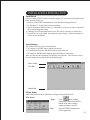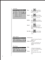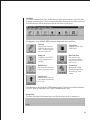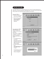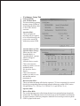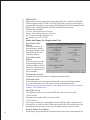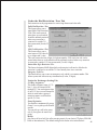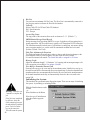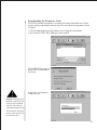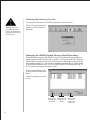
1
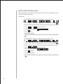
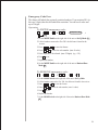
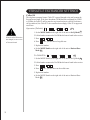
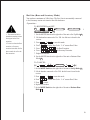
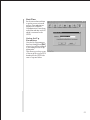
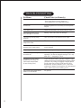
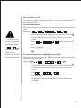
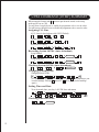
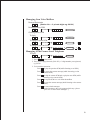
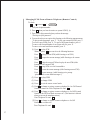
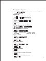
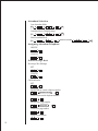
Public Dial Restriction
This feature allows assigned telephone number restrictions to be entered
or removed. For example, if you enter 1(800)555-5555 which has 11
digits, this exact phone number is blocked for outgoing calls. You can
have 8 codes and up to 25 digits of restricted numbers.
Operation:
To INPUT public dial restriction code:
(1 8 (
4
S
Telephone No.
#
N
1. Set the MODE Switch on the right side of the unit to Set-Up Mode S
2. Lift the handset connected to Ext. 200 - the dial tone is heard in the receiver.
4 to enter the feature.
3. Press
4. Press ( 1
8 ( to enter the code number. (max. 8 codes)
5. Press telephone number to be restricted. (max. 25 digits)
6. Press # to set.
7. Replace the handset.
8. Set the MODE Switch on the right side of the unit to Business-Hour Mode
N
To FREE public dial restriction code:
(1 8 (
4
S
N
1. Set the MODE Switch on the right side of the unit to Set-Up Mode S
2. Lift the handset connected to Ext. 200 - the dial tone is heard in the receiver.
4 to enter the feature.
3. Press
4. Press ( 1
5. Press
8 ( to enter the code number. (max. 8 codes)
to free.
6. Replace the handset.
7. Set the MODE Switch on the right side of the unit to Business-Hour Mode
N
32
Station Public Dial Restriction
The 8 restriction codes you have entered (see page 32), now need to be registered to each
extension to activate restriction.
Operation:
To ENABLE extension public dial restriction code:
)2 0 0 2 1 5 )
0 5
#
S
N
1. Set the MODE Switch on the right side of the unit to Set-Up Mode S
2. Lift the handset connected to Ext. 200 - the dial tone is heard in the receiver.
0 5 to enter the feature.
3. Press
4. Press the station number ) 2 0 0
2 1 5 )
5. Press # to set.
6. Replace the handset.
7. Set the MODE Switch on the right side of the unit to Business-Hour Mode
N
To DISABLE extension public dial restriction code
)2 0 0 2 1 5 )
0 5
S
N
1. Set the MODE Switch on the right side of the unit to Set-Up Mode S
2. Lift the handset connected to Ext. 200 - the dial tone is heard in the receiver.
3. Press
0 5 to enter the feature.
4. Press the station number ) 2 0 0
5. Press
2 1 5 )
to disable.
6. Replace the handset.
7. Set the MODE Switch on the right side of the unit to Business-Hour Mode
N
33
Emergency Code Free
This feature will unlock the previously restricted numbers. If you restricted 911 (in
this case 3 digits) then this will unlock the restriction. You can have 8 codes and
up to 25 digits.
Operation:
To ENTER emergency code :
5
S
#
(1
8 (
Telephone No.
N
1. Set the MODE Switch on the right side of the unit to Set-Up Mode S
2. Lift the handset connected to Ext. 200 - the dial tone is heard in the
receiver.
5 to enter the feature.
3. Press
4. Press ( 1
8 ( to enter the code number. (max. 8 codes)
5. Press telephone to be released. (max. 25 digits) (e.g. : 911 )
6. Press # to set.
7. Replace the handset.
8. Set the MODE Switch on the right side of the unit to Business-Hour
Mode N
To REMOVE emergency code:
5
S
(1
8 (
N
1. Set the MODE Switch on the right side of the unit to Set-Up Mode
2. Lift the handset connected to Ext. 200 - the dial tone is heard in the receiver.
5 to enter the feature.
3. Press
4. Press ( 1
5. Press
8 ( to enter the code number. (max. 8 codes)
to free
6. Replace the handset.
7. Set the MODE Switch on the right side of the unit to Business-Hour Mode
N
34
VERSATILE EXCHANGER SETTINGS
Caller ID
The telephone company feature ‘Caller ID’ is passed through to the unit between the
first and second rings. If the Auto Attendant (OGM) has been configured for OGM1
or OGM6, the Caller ID will be passed to any extension that is selected. Each time a
call is transferred, the Caller ID is also transferred accordingly. Caller ID is supported
on all lines.
Operation (Default): S
8 0
#
N
1. Set the MODE Switch on the right side of the unit to Set-Up Mode S
2. Lift the handset connected to Ext.200-the dial tone is heard in the receiver.
When the caller ID function
has changed, be sure to turn
off the main board.
3. Press
8 0
4. Press # to set – you will hear a long dial tone.
5. Replace the handset.
6. Set the MODE Switch on the right side of the unit to Business-Hour
Mode N
To CANCEL: S
8 0
N
1. Set the MODE Switch on the right side of the unit to Set-Up Mode S
2. Lift the handset connected to Ext.200-the dial tone is heard in the receiver.
3. Press
4. Press
8 0
to set – you will hear two short dial tones.
5. Replace the handset.
6. Set the MODE Switch on the right side of the unit to Business-Hour
Mode N
35
Hot Line (Boss and Secretary Mode)
You can have a maximum of 4 Hot Lines. The Boss Line is automatically connected
to the Secreatary station each time the Boss lifts the hanset.
Operation :
To REGISTER and SET:
7 5
S
1. The extension 200 (or
attendant extension) can not
be assigned to the Boss
extension.
2. To dial out from the Boss
extension, a Secretary
extension must dial out first
then transfer the call to the
Boss extension.
Boss: (1-4)
Boss: (201-215)
N
Secretary: (200-215)
1. Set the MODE Switch on the right side of the unit to Set-Up Mode S
2. Lift the handset connected to Ext. 200 - the dial tone is heard in the
receiver.
7 5 to enter this mode.
)
1
4
) to select Boss Code. “1~4” means Boss Codes.
4. Press
5. Press ) 2 0 1 2 1 5 ) for Boss Extension.
3. Press
6. Press ) 2 0 1
2 1 5 ) for Secretary Extension.
7. Replace the handset.
8. Set the MODE Switch on the right side of the unit to Business-Hour
Mode N
To CANCEL:
S
7 5
Boss: (1-4)
N
1. Set the MODE Switch on the right side of the unit to Set-Up Mode S
2. Lift the handset connected to Ext. 200 - the dial tone is heard in the
receiver.
3. Press
4. Press ) 1
5. Press
7 5 to enter this mode.
4 ) to select Boss Code. “1~4” means Boss Codes.
to cancel.
6. Replace the handset.
7. Set the MODE Switch on the right side of the unit to Business-Hour
Mode N
36
Flash Time Adjustment for C.O. Lines
The Flash time means the actual time it takes to depress and release the plunger or the
actual handset-cradle to create a signal to the unit to put the caller on hold. The Initial
flash time is assigned at 100 msec.
6 1
Operation: S
)1
9 )
N
1. Set the MODE Switch on the right side of the unit to Set-Up Mode S
2. Lift the handset connected to Ext. 200 - the dial tone is heard in the receiver.
6 1 to enter the feature.
)
)
1
9
4. Press
to select ring number. () 1 9 ) means 100ms ~900ms.
E.g.: Press 5 for 500ms.)
3. Press
5. Replace the handset.
6. Set the MODE Switch on the right side of the unit to Business-Hour Mode
N
Flash Time Adjustment for Extensions
The Flash time means the actual time it takes to depress and release the plunger or the
actual handset-cradle to create a signal to the unit to put the caller on hold. It is used for
internal call transfer. You can change the flash time value from 60msec up to 990msec.
The default flash time is assigned at 150msec.
6 6
Operation: S
)1 0
9 9 )
N
1. Set the MODE Switch on the right side of the unit to Set-Up Mode S
2. Lift the handset connected to Ext. 200 - the dial tone is heard in the receiver.
3. Press
6 6 to enter the feature.
4. Press ) 1 0 9 9 ) to select ring accounts. () 1 0
100ms~990ms. e.g.: Press 6 5 for 650ms.)
9 9 ) means
5. Replace the handset.
7. Set the MODE Switch on the right side of the unit to Business-Hour Mode
N
37
Selecting Printout for SMDR (Extension Message Detail Recording)
To use this feature a PC must
be connected to the UPBX
system. Before using this
feature from the attendant
extension run the UPBX
communication centre
programme and activate the
SMDR window.
Extension message detail recording (SMDR) is a type of telephone call accounting that
is usually captured in ASCII text and sent to a printer or PC through an RS-232 connection
(Default: Not Used).
Operation:
To a PC: S
6 4
1
N
1. Set the MODE Switch on the right side of the unit to Set-Up Mode S
1. Lift the handset connected to Ext. 200 - the dial tone is heard in the receiver.
2. Press
6 4to enter the feature.
3. Press 1 to select PC.
4. Replace the handset.
5. Set the MODE Switch on the right side of the unit to Business-Hour Mode
N
To a Serial Printer: S
6 4
2
N
1. Set the MODE Switch on the right side of the unit to Set-Up Mode S
2. Lift the handset connected to Ext. 200 - the dial tone is heard in the receiver.
3. Press
6 4 to enter the feature.
4. Press 2 to select a serial printer.
5. Replace the handset.
6. Set the MODE Switch on the right side of the unit to Business-Hour Mode
N
Not used (default): S
6 4
0
N
1. Set the MODE Switch on the right side of the unit to Set-Up Mode S
2. Lift the handset connected to Ext. 200 - the dial tone is heard in the receiver.
3. Press
6 4 to enter the feature.
4. Press 0 to select a serial printer.
5. Replace the handset.
6. Set the MODE Switch on the right side of the unit to Business-Hour Mode
N
38
Adjusting the Maximum Recording Length of ICM and OGM
Adjust the maximum length (“1~10 minutes”) of outgoing messages and incoming
message to be left in the extension voice mailbox. The default is 1 minute.
)0 1 1 0 )
N
6 9
Operation: S
1. Set the MODE Switch on the right side of the unit to Set-Up Mode S
2. Lift the handset connected to Ext.200-the dial tone is heard in the receiver.
3. Press
6 9
)
4. Press ) 0 1 1 0 ) to select the minute input. ( ) 0 1 1 0
0
5
means 1~10 minutes. e.g.: Press
for 5 minutes) - you will hear a
long dial tone.
5. Replace the handset.
6. Set the MODE Switch on the right side of the unit to Business-Hour
Mode N
Selecting the Voice Mail for Unattended External Calls
External calls can be put through to a voice mail at the attendant station automatically.
Initially they can't go to the mail box and will be disconnected after a pre-assigned number
of rings. In the auto-attendant and attendant modes they are automatically diverted to
the voice mail at the attendant station. In the multi-attendant mode they are automatically
diverted to the voice mail at the station 200 .
Operation:
ENABLE the voice mail:
6 5
N
1. In the business hour mode
S
you can select the voice mail
1. Set the MODE Switch on the right side of the unit to Set-Up Mode S
for unattended external
calls.
#
2. Lift the handset connected to Ext. 200 - the dial tone is heard in the receiver.
unattended external calls
6 5
# - you will hear a long dial tone.
3. Press
4. Replace the handset or press telephone hook to get a new dial tone.
will be automatically
5. Replace the handset.
diverted to the voice mail at
6. Set the MODE Switch on the right side of the unit to Business-Hour Mode N
2. In the off-hour mode
the attendant station.
DISABLE the voice mail (default):
6 5
S
N
1. Set the MODE Switch on the right side of the unit to Set-Up Mode S
2. Lift the handset connected to Ext. 200 - the dial tone is heard in the receiver.
6 5
3. Press
- you will hear two short dial tones.
4. Replace the handset or press telephone hook to get new dial tone.
5. Replace the handset.
6. Set the MODE Switch on the right side of the unit to Business-Hour Mode
39
N
Registering Group for a call pick-up
You can have a maximum of 4 groups. Group 1 is able to pick-up calls from all extensions.
You can pick up a call in the group only if you register the extension as a group.
Operation: S
(2 0 0
(1
7 4
2 1 5 (
#
4 (
N
1. Set the MODE Switch on the right side of the unit to Set-Up Mode (S).
2. Lift the handset connected to Ext. 200 - the dial tone is heard in the receiver.
3. Press
7 4 to enter the “Registering Group” mode.
1 if you want to register a
4. Press ( 1 4 ( to select Group number.
5. Press ( 2 0 0 2 1 5 ( to choose extensions from 200 to 215
you wish to group. You don’t have to choose any stations if you select
Group 1 from step 4.
new Group (1~4).
6. Press # to set the group. (or press
1. Reset the initial Group
2. An extension can be
registered in two Groups.
to reset the group.) (i.e.: Press
2 0 0 # 2 0 1 # 2 0 2 # 2 0 3 # 2 0 4 #
in series if you want to group from 200 to 204.)
For example, the extension
7. Repeat step 5 for other station numbers.
202 can be registered at
8. Replace the handset.
Group 1 and Group 2.
9. Set the MODE Switch on the right side of the unit to Business-Hour Mode
C.O. Ring Assignment (Multi attendant mode only)
You can designate rings of one C.O. line to several extensions. This is useful when a
group of extensions answer calls from the specific C.O. line. The pre-assigned extensions
as the default setting are extension 200 and 204 for C.O.1, 201 for C.O.2, 202 for C.O.3
and 203 for C.O.4.
For more details,
see page 27 ‘Attendant
Selection’
Operation: S
(2 0 0
0
2 1 5 (
(1
#
4 (
N
1. Set the MODE Switch on the right side of the unit to Set-Up Mode S
2. Lift the handset connected to Ext. 200 - the dial tone is heard in the receiver.
3. Press
0 to enter the feature.
4. Press ( 1 4 ( to select C.O. line.
5. Press ( 2 0 0 2 1 5 ( to choose extensions from 200 to 215 you
wish to group. (e.g. : Press 2 0 0 # 2 0 1 # 2 0 2 #
2 0 3 # 2 0 4 in series if you wish to group from 200 to 204.)
6. Press # to set the group (or press
to reset the group).
7. Repeat step 5 through 6 for another designation or cancellation
8. Replace the handset.
9. Set the MODE Switch on the right side of the unit to Business-Hour Mode
N
40
Uniden UPBX416
Communication Centre
41
INSTALLATION & INTRODUCTION
Installation
Once the Uniden UPBX416 and the Personal Computer (PC) are connected through the serial
cable, turn both of these on.
1. Insert the Uniden UPBX Communication Centre disk into the floppy disk drive.
2. For Windows 95 / 98 select Run from the Start Menu.
3. Type the appropriate disk drive letter eg: a: (followed by) \setup.exe (a:\setup.exe) and select
OK to start the programme setup.
4. A dialogue box will open and all the necessary files will be extracted to your hard drive.
5. Once the files have been loaded, the programme setup will begin. Follow the prompts for
a quick and easy installation.
Introduction
The Uniden UPBX416 has three main functions.
1. To configure your UPBX using a graphic user interface.
2. To download the firmware code into the flash memory in the unit.
3. To manage the SMDR (Station Message Detail Recording) by each station.
When you first open the programme, the following screen appears. There are three areas in
the main window that are described in the following pages.
Menu Items
Tool Bar
Status Bar
Menu Items
Most UPBX functions can be controlled or configured using the Menu items.
File Menu:
Setup -
(Also
in the Toolbar)
Allows you to select the COM Port
that the serial cable is using to
connect your unit to your PC.
Exit -
Exits the UPBX Communication
Centre Application.
42
Job Menu:
Setup -
(Also
in the Toolbar)
Configures your UPBX using a
graphical user interface
Upgrade - (Also
in the Toolbar)
Downloads the firmware code into
the flash memory in the unit.
Initialize - (Also
in the Toolbar)
Initialises the system and erases all
previous inputs.
Journal -
(Also
in the Toolbar)
Manages the SMDR (Station
Message Detail Recording) by each
station.
Date/Time - (Also
in the Toolbar)
set to get the correct voice mail
services.
Option Menu:
A Period of store A period of storing call events by
month or year.
Number of Call Events A number of Call Events to be
displayed at once in the view
window.
Help Menu:
About-
Version -
A dialogue box displaying the
programme copyright and version,
and the company logo.
EPROM Version of the UPBX
Series.
43
Toolbar
The UPBX Communication Centre Toolbar gives you quick and easy access to some of its most
frequently used menu items. To select an item on the toolbar simply place your mouse cursor over
the toolbar item you wish to use/open and click the left button on your mouse.
Configures your SOHO PBX using a graphical user interface.
Port icon
Allows you to select the
COM Port that the serial
cable is using to connect
your unit to your PC.
Version icon
EPROM Version of the
UPBX Series.
Setup icon
Configures your UPBX
using a graphical user
interface.
Date/Time icon
You should set the
current time and date
to get the correct voice
mail services.
Initialize icon
Initializes the system and
erases all previous inputs.
Journal icon
Manages the SMDR
(Station Message Detail
Recording) by each
station.
Upgrade icon
Downloads the firmware
code into the flash memory
in the unit.
Date and time are displayed on UPBX Communication Centre from settled data and time
set for PC which is connected to the UPBX Communication Centre.
Status Bar
The Status Bar shows which menu item or toolbar item your cursor is currently on.
44
HOW TO USE
The UPBX toolbar gives you quick and easy access to some of its most frequently used
menu items. To select an item on the toolbar simply place your mouse cursor over the toolbar
item you wish to use/open and click the left button on your mouse.
Selecting COM Port
1. Press Port icon (or select
Port on the File Menu).
2. Select the Port you wish
to use, (see opposite)
then press the OK
button.(COM1 is
defaulted)
Programming the UPBX
Click the Setup on the
Toolbar (or Select Setup on
the Menu).
The window ( see opposite)
will appear. It provides the
process for getting the
information already set in the
UPBX.
1. From UPBX (Exclude
voice mail).
Reads data from UPBX
which has been already set.
Shows all the data set on
UPBX currently.
2. From PC (Exclude voice
mail).
Loads setup functions from
a stored file on your
computer.
The data being set up by
your PC is plotted on
screen (see opposite).
45
Exchanger Setup Tab
Exchanging Mode
Auto Attendant Mode:
This is used when the greeting
message (system OGMs) for
all incoming calls allows caller
to direct call to desired
extension.
Attendant Mode:
This is used when all
incoming calls are required
to be received directly by the
person at the station 200
without any system OGM.
Attendant Station and SubAttendant Station Settings:
]When you click ‘Auto
Attendant Mode’ or
‘Attendant Mode’ a pop-up
window will appear
(opposite).
Attendant Station number:
Click on the extension
number you wish to set as an
attendant Station.
Sub Attendant Station
Number:
Click on the extension
numbers you wish to set as
sub attendant stations
(maximum 4).
Multi-Attendant Mode:
This is used when incoming calls from the respective C.O. line are required to be received
directly by corresponding stations already assigned without any system OGM. (station
200 and 204 for C.O. 1, 201 for C.O. 2, 202 for C.O. 3, and 203 for C.O. 4.)
Operation Mode
Business-Hour Mode:
The recorded message greets callers during business hours and guides them through the
system menu. The Caller may choose to be routed to any of the 16 available local extensions,
or remote extension. Callers are prompted to make their choices using a touch tone phone.
OGM1 is played in this mode.
46
Off-Hour Mode:
An alternate recorded message can be played during off- hours, weekends, and holidays.
OGM 6 is played instead of OGM1. In the Off Hour Mode you can receive messages or
get urgent calls forwarded to you by using the Call Notification and Call Forwarding Outside
features. Refer to Call Notification and Call Forwarding Outside features.
C.O Lines Use / Not Use:
C.O lines : Central office lines to be used.
Not use : Central office line(s) not to be used.
All C.O lines are initially assigned for use.
“ ” indication is to use C.O. Line
Under the Phone No. Registration Tab
Station Memory Dial
Numbers
Each station can store 10
personal memory dials by
using Station Memory Dial
Input feature for fast and
convenient dialling.
System Memory Dial
Numbers
This feature allows you fast
and convenient dialling of
telephone numbers stored in
the system. All stations have
access to a common pool of
up to 40 numbers.
Call Forward to Extension
Incoming calls can be forwarded to a designated extension number.
Call forward outside
From each station, you can forward incoming calls to an outside telephone number
(e.g. your cellular phone or an office phone you are visiting) automatically.
To use this feature, you have to request a 3 way calling service from your local telephone
company. (New Zealand only).
Out-of-Office Services
You can preset several services from the UPBX when you are out of the office.
- Station numbers
Assign the station number when you leave the office.
- Call Notification
If you set your station in the unattended mode and somebody leaves a message in your
voice mail box, you will be notified. While other people in the office can directly receive
incoming calls you can remote control your incoming calls from outside the office.
47
Telephone Number in the Off-Hour
This is only for urgent calls and the call forward can be done from a virtual extension 216.
Under the Dial Restriction / Free Tab
Each extension can be programmed to restrict long distance and other calls.
Public Dial Restriction / Free
This feature allows you to
input Public Dial Restriction
Code. This can be entered
when there are codes which
should be uniformly restricted
when every extension is
connected to outside C.O.
lines system-wide (8 codes, 25
digits).
COS Code Restriction / Free
This feature allows you to
enter/remove COS codes for
up to 4 digits and 3 codes.
This code restricts the first 4 digits of telephone number. COS restriction code can be
entered when there are codes which should be uniformly restricted when every extension
is connected to outside C.O. lines system-wide (3 codes, 4 digits).
Station Max. Digit Restriction / Free
This feature designates MAX digits which each extension is allowed to dial after the
extension is connected to an outside C.O. line. Initially, there is no restriction.
Emergency Code Free
This feature allows you to enter an emergency code, which is a common number. This
allows system-wide callout in any circumstances (8 codes, 25 digits).
Under the Exchanger Setting Tab
C.O. Ring Assignment
This feature designates rings of C.O.
line (1 ~4) to the extensions 200
through 215. You can designate rings
of one C.O. line to several extensions
which is useful when a group of
extensions answer a call from the
specific C.O. line.
Group Registration
You can have a maximum of 4 groups.
Group 1 is set to pick-up calls from all
stations.
You can pick up a call in the group
only if you register the station as a
group.
Melody
Any time a call is on hold, the caller can enjoy music of your choice (CD player, FM/AM
Radio or Internal music). The default setting for this feature is the internal music.
48
Hot Line
You can have a maximum of 4 Hot Lines. The Boss Line is automatically connected to
the Secretary station each time the Boss lifts the handset.
Caller-ID
Selects Caller ID On/Off and Caller ID Standard.
Bell : North America
V.23 : Europe
Answer Ring Count
The ring count of the extension lines can be set between 5 ~ 11. (Default : 7 )
SMDR(Station Message Detail Record)
Station message detail recording (SMDR) is a type of telephone call accounting that is
usually captured in ASCII text and sent to a printer or PC through an RS-232 connection.
The information usually includes start of call indicator, trunk group, user name, calling
party extension number, etc., and is useful for automated attendant and voice mail
systems. (Default : Not Used)
Flash Time Adjustment for Extensions
The Flash time means the actual time it takes to depress and release the plunger or the
actual handset-cradle to create a signal to the unit to put the caller on hold.
It is used for internal call transfer. The Initial flash time is assigned for 150 msec.
Message Length
Adjust the maximum length (“1~10minutes”) of outgoing and incoming messages to be
left in extension voice mailbox. One minute is default.
Voice Mail for Unattended External Calls
External calls can go to the voice mail at the attendant station. Initially they can't go to
the mail box and will be disconnected after pre-assigned rings. In the auto-attendant and
attendant modes they are automatically diverted to the voice mail at the attendant station.
In the multi-attendant mode they are automatically diverted to the voice mail at the
station 200.
Initialising the System
This initialises the system and erases all previous inputs. There are two ways of initialising
the system - by including or excluding OGMs.
Warning: It may take over
3 minutes to complete the
job.
If the job is not completed
by this time, check the
cable connection between
the unit and the PC and then
press “Ctrl+Alt+Delete “
keys at the same time.
This will restart the system.
49
Click the Initialize button on the
Toolbar
- or Select Initialize on the Menu.
Select the type of initialization
when the window opposite
appears.
Downloading the Firmware Code
The UPBX’s firmware programme or operating code can be downloaded into a Flash
memory without removing the memory chip in the unit. Check the programme version
in advance.
1. Click the Upgrade button on the Toolbar (or select Upgrade on the Menu)
2. Select the file of PBX*,BIN (128K Byte) in the window.
This WARNING message will
appear. Press continue button
to proceed.
It may take over 3 minutes to
complete the job.
Warning: It may take over 3
minutes to complete the job.
If the job is not completed
after this time, check the
cable connection between the
unit and the PC. Then press
Ctrl,Alt, Del at the same time
to restart the system.
50
Checking the Firmware Version
You can get the information of EPROM programme version in the unit.
Warning: Check the
programme version in
advance to download the
programme code into the
Flash memory.
Click the Version button on the
Toolbar (or Select Version on
the Menu).
Managing the SMDR (Station Message Detail Recording)
Station message detail recording (SMDR) is a type of telephone call accounting that is
usually captured in ASCII text and sent to a printer or PC through an RS-232 connection.
The information usually includes start of call indicator, trunk group, user name, calling
party extension number, etc., and is useful for automated attendant and voice mail systems.
To get SMDR information in the PC, set the SMDR option of the Setup menu to th “To
PC” in advance and keep the Journal List open.
Click the journal button on the
Toolbar (or Select Journal on the
Menu).
Follow the prompts to get other
services.
Delete:
Print:
Review:
Prints calls to Views calls to be Deletes calls to
be displayed in displayed in the be stored by
month or year
the journal.
journal.
and station.
51
Date/Time
Set the current date and time
to get the correct voice mail
services. Date and time are
displayed on UPBX416
Communication Centre from
settled data and time set for PC
which is connected to the
UPBX.
Saving Set Up
Parameters
Once the Set Up parameters
have been changed and OK
selected, you will be prompted
to save changes to the set up
information.
This allows you to keep a copy
of the set up file on your PC to
download to the UPBX i the
event of a power failure.
52
TROUBLESHOOTING
53
Problems
Check Point (or Remedy)
The unit does not work.
Check power source
- Is the power adaptor correctly plugged in ?
- Is the telephone line cord connected correctly?
No dial tone
Plug the telephone line cord securely into the telephone
line jack
I can’t make a call
Check if the dial mode (Tone/Pulse) setting is correct
The answering function is on,
but no messages are recorded.
Memory is full. Erase some or all messages
The unit stops working during
operation
Turn off the unit to reset and then turn on again
While operating the unit, the AC
adaptor feels warm
This is the normal condition
I cannot retrieve recorded
messages from a remote phone
Make sure that you use the
correct password
I forgot my password
Register a new password again
I use Line 1 only. I cannot place
an outside call
The default setting of C.O. Line mode is using all 4 lines.
repeatedly. You have to change the setting to C.O.1 only
mode. See “ 3. Assigning C.O. lines”.
Telephone line is not released
immediately after using - the
Call forward outside feature.
(in case of using 1 line)
To use call forward outside , you have to request a 3 waycalling service from your local telephone company. When
you finish 3-way calling, the telephone company should
provide a busy tone to let the UPBX know the call is
disconnected. In most countries it won’t - so the call is
restricted to 3 minutes. Even though the call is disconnected
earlier, UPBX waits for the remaining period.
Can I use the call forward outside
feature in off hour mode ?
Yes, you can.
Power Failure or Off
You can use the telephone during a power failure or off. You can use Line1 and Line 2
with station 200 and 201.
System Initialisation
This feature sets the system at a cold start. It initialises the systems and erases all previous
inputs.
2 5 8 0
Operation: S
# #
N
1. Set the MODE Switch on the right side of the unit to Set-Up Mode S
1. It will take about 40
seconds to be ready after
initialising the system.
# should
2. 8 0
be set at the attendant
telephone before
initialising the system in
the multi-attendant mode.
2. Lift the handset connected to Ext. 200 - the dial tone is heard in the
receiver.
3. Press
2 5 8 0
# # to set the system at a cold
start.
4. Replace the handset.
5. Set the MODE Switch on the right side of the unit to Business-Hour Mode
N
System Initialisation excluding System OGMs
This feature sets the system at cold start. It initialises the system and erases all previous
inputs except the system OGMs.
Operation: S
2 5 8 1
# #
N
1. Set the MODE Switch on the right side of the unit to Set-Up Mode S
2. Lift the handset connected to Ext.200- the dial tone is heard in the
receiver.
3. Press
2 5 8 1
# #
4. Replace the handset.
5. Set the MODE Switch on the right side of the unit to Business-Hour
Mode N
54
UPBX COMMAND (DTMF) SUMMARY
When setting the features with S you must put the mode switch on the set-up
mode and do it at ext. 200.
You will hear a long dial tone to enable the programme code or set the value.
You will hear two short dial tones to disable the programme code or reset the value.
Assigning C.O. Line
4 C.O. Lines for the telephone calls ONLY (Default)
S
6 7
2
N
Disable Not-Used C.O. Line(s)
S
1 0
)1
4 )
N
)1
4 )
#
Re-Used C.O. Line(s)
S
1 0
N
Recording System OGMs (Auto-Attendant)
Using Handset:
S
7 1
(1
7 (
Recording
N
7 2
(1
7 (
Recording
N
Using MOH port:
S
Checking System OGMs (Auto-Attendant)
S
7 3
(1
8 (
Checking
N
Changing System OGMs
Changing System OGMs
N
( # or (
(1 8 (
(You can select the original station message if you press
when listening to your
recorded message. Pressing # instead of selects your recorded message
again.)
S
7 3
Setting Time and Date
To set the month, date, year, day, A.M./P.M. hour and minute
Checking Time and Week
5 9
55
Listening
Managing Own Voice Mailbox
Password Registration
)Station No. + 2 private digits eg: 20134 )
5 1
Recording Station OGM
5 2
Password )e.g. 2 0 1 3 4 )
Recording
Checking Station OGM
To check
5 3
Password )e.g. 2 0 1 3 4 )
Listening
To change to system OGM
5 3
Password )e.g. 2 0 1 3 4 )
Listening
To change to your own OGM
5 3
Password )e.g. 2 0 1 3 4 )
Listening
#
Managing ICMs From a Local Telephone
To check:
5 4
Password )e.g. 2 0 1 3 4 )
Listening
1. Press 5 4 to play ICMs.
2. Press your 5-digit password; (200~215) + 2-digit number you registered;
e.g. 20134.
3. Voice mailbox operation:
Press 1 to play the previous ICM (while listening to an ICM )
Press 2 to repeat the current message (while listening to the
current ICM )
Press 3 to skip the current ICM and to play the next ICM (while
listening to the current ICM)
Press 5 to stop the ICM or to exit from the mailbox
Press 6 to erase the current message (while listening to the current
ICM )
Press 0 to erase whole messages.
(while listening to the voice prompt which says “please
press zero to erase whole messages.”)
56
Managing ICMs From a Remote Telephone (Remote Control)
To check:
Password
Listening
1. Call your telephone number.
2. Press
when you hear the station or system OGM (1, 6).
3. Press your 5-digit password when you hear the message.
“Please press your password.”
4. You can then choose an option after listening to the following announcement.
“To play recorded messages, press ‘2’. To play your extension OGM, press ‘3’.
To record a new OGM, press ‘4’. To enter a call-forward number, press ‘6’.
To enter a call-forward number for an Urgent call 416, press ‘8’.
To enter a voice mail notification number, press ‘9’.
(1) Press 2 to play ICM
When you press 2 , you can select the following functions.
Press 1 to play previous ICM (while listening to an ICM )
Press 2 to repeat the current message (while listening to the current
ICM)
Press 3 to skip the current ICM and to play the next ICM (while
listening the the current ICM)
Press 5 to stop ICM or to exit from mailbox
Press 6 to erase the current message (while listening current ICM )
Press 0 to erase messages. (while listening voice prompt
“please press 0 to erase whole messages.”)
(2) Press 3 to play OGM.
(3) Press 4 to change OGM
(4) Press 5 to exit the remote control mode.
(5) Press 6 to change or register a remote telephone No. for Call Forward
Outside at remote site. Press Telephone No. and # .
(6) Press 8 to change or register a remote telephone no. for Call Forward
Outside in the Off Hour Mode at remote site. (This function is allowed
when you access the attendant station)
Press Telephone No. and # .
(7) Press 9 to change or register a remote telephone no. for Call
Notification at remote site.
Press Telephone No. and # .
57
Basic Telephony Operations
Intercom Calls
Press ( 2 0 0 2 1 5 ( (this means choose any extension between 200 and
215 that you wish to call).
Outside Call
Press 0 to obtain a free line for an out-going call.
Telephone No.
( 1 4 (
Press 8
Call Transfer
Flash
( 2 0 0
2 1 5 ( or 9
Call Pickup
#
Leaving a Message after a Call Pickup
Flash
(2 0 0
7 7
2 1 5 (
Recording
Leaving a Message by extension
7 7
(2 0 0
2 1 5 (
Conference Call / 3 Way Calling
Flash
Third Station Dialling
Flash or Hook
Station Callback
SET
6 3
(2 0 0
2 1 5 (
CANCEL
6 3
C. O. Line Callback
SET
6 3
)8 1
8 4 ) or 0
CANCEL
6 3
Last Number Redial
6 5
Call Screen
MONITOR and/or TALK with OGM Recording
8 8
MONITOR and/or TALK without Recording
8 8
58
Attendant Selection
Auto Attendant Mode
6 3
S
N
#
Attendant Mode (Default Setting)
N
6 3
S
Multi-Attendant Mode
6 3
S
Hook On and Off
Assigning Attendant Telephone
ASSIGN
6 8
#
CANCEL
6 8
When Leaving a Desk
Receiving Caller Messages
SET
5 5
#
CANCEL
5 5
Call Notification
SET
5 8
#
REGISTER an outside telephone number.
5 6
#
Telephone No.
CANCEL an outside telephone number.
5 6
REGISTER a page number.
5 7
Page No.
CANCEL a page number.
5 7
CANCEL this feature.
5 8
59
#
6 8
N
Call Forwarding
Call Forwarding to Extension Number
REGISTER and SET
6 2
)2 0 0
2 1 5 )
CANCEL
6 2
Call Forwarding Outside
REGISTER
6 6
Telephone No.
#
SET
6 6
#
CANCEL
6 6
Memory Dial
Extension Memory Dial Input / Output
INPUT number
)0 0
6 4
0 9 )
Telephone No.
#
Telephone No.
#
DIAL out
6 1
)0 0
0 9 )
)0 0
0 9 )
CANCEL
6 4
System Memory Dial Input / Output
INPUT (at Extension 20)
)1 0 4 9 )
6 4
DIAL OUT
6 1
)1 0
4 9 )
)1 0
4 9 )
CANCEL
6 4
60
Off Hour / Business Hour Services
Setting the Off-Hour Mode
SET by Mode Switch Set the Mode Switch on the right side of the Unit to Of Hour Mode OH
SET by Telephone 7 5
#
CANCEL by Mode Switch Set the Mode Switch to Business Hour Mode N
CANCEL by Telephone 7 5
SETTING the Business Hour Mode
SET the MODE switch on the right side of the Unit to Business Hour Mode N
URGENT Call
REGISTER
S
6 7
Telephone No.
6 7
#
#
OH
SET
S
OH
CANCEL
S
6 7
OH
Off Hour / Business Hour Services
Call ID
ENABLE
8 0
S
N
#
CANCEL
8 0
S
N
Hot Line (Boss and Secretary Mode)
REGISTER and SET
S
7 5
Secretary: 200-215
)1
4 )
)1
4 )
Boss: 201-215
N
CANCEL
S
61
7 5
N
Flash Time adjustment for C.O. Lines
)1 9 )
6 1
S
N
Flash Time Adjustments for Extensions
6 6
S
)1 0 9 9 )
N
Music On Hold
INTERNAL
S
0 8
N
#
EXTERNAL
S
0 8
N
SELECTING Printout for SMDR
To PC
S
6 4
1
N
6 4
2
N
6 4
0
N
To SERIAL PORT
S
Not Used (Default)
S
SET Number of Rings before Answer
S
6 0
Ring No. (05-11)
N
ADJUSTING the maximum Recording Length of ICM and OGM
(1 - 10 Minutes)
6 9
N
S
)0 1 1 0 )
SELECTING the Voice Mail for Unattended External Calls
ENABLE
6 5
S
N
#
DISABLE (Default)
S
N
6 5
REGISTERING Group for a Call Pickup
REGISTER
S
(2 0 0
)0 1
7 4
2 1 5 (
0 4 )
N
#
CANCEL
S
(2 0 0
7 4
2 1 5 (
)0 1
0 4 )
N
62
NOTIFICATION on 3 Way Calling
ESTABLISH
0 9
S
(2 0 0
CANCEL
0 9
S
(2 0 0
2 1 5 (
N
#
2 1 5 (
C.O. Ring Assignment (Multi Attendant)
)0 1 0 4)
0
S
N
(2 0 0 2 1 5 (
#
Dial Restriction
Class of Service (COS) Code Restriction
ENTER
)1 3 )
Telephone No.
1
S
N
#
N
REMOVE
Telephone No.
)1 3 )
Station Maximum Digit Restriction
RESTRICT
)2 0 0 2 1 5 )
3
S
)0 0 9 9 )
N
FREE
)2 0 0 2 1 5 )
3
S
1
S
Public Dial Restriction
INPUT
)1
4
S
Telephone No.
#
8 )
N
FREE
S
4
)1
8 )
5
)1
8 )
5
)1
8 )
N
Emergency Code
ENTER
S
#
Telephone No.
N
REMOVE
S
N
System Initialisation
Initialise
S
2 5 8 0
# #
Initialise (excluding system OGM’s)
S
63
2 5 8 1
# #
N
N
TECHNICAL SPECIFICATION
System Configuration
Call Processing Mode
C.O. line: 4 lines
Extension: 16 Extensions
Power: 24V DC, 1.2A AC Adaptor
Auto Attendant Mode with DIDS.
Multi-Attendant Mode.
Attendant Mode.
Features
Voice Mail
Dial:
- Extension memory dial (10ea/extension)
- System memory dial (40ea)
- Last number redial
Intercom Call
Call-back:
- Extension callback (200-215)
- C.O. line callback (0,81,82,83,84)
Call-Forwarding:
- Extension call- forwarding (200-215)
- C.O. line call- forwarding outside (phone,
cellular)
Call Conference:
- 3 Extensions
- 1 C.O. Line & 2 Extensions
Call-Transfer
DIDS(direct inward dialing system) or
DISA (direct inward system access)
Call-Pickup
C.O. Line Restriction (max digit/ special
public dial number/ first four digit)
Melody Source (internal/external)
Individual Voice Mail Box.
Voice Prompt or Changeable System OGM.
Remote Control for Voice Mail.
Auto Call-Forwarding outside of your call.
Auto Call- Notification of your Voice Mail
(to phone , beeper or cellular).
Hot Line (boss- secretary)
Rest Group Assign (max. 4 group)
Business or Off Hour Mode Assign.
Urgent Call Routing for Off- Hour Mode.
SMDR
Voice Mail (Total recording time 40 mins).
Caller-ID support.
System Set-Up through PC (rs-232c)
Down Loadable System Program.( PC to
Flash ROM)
Set-Up Data Monitoring.
DSP Technology
No Need for Back-Up Battery.(Flash Memory)
Total Recording Time (1 Hour)
Voice Prompt
Real Time Clock
Individual OGM/ICM Management for
Extension.
Caller-ID
Bell 202 Support (FSK)
- type 1
- single / multi signal
ITU-TV.23 (under development)
Electrical & General Specifications.
General
- C.O. Line
- Extension Line
- Power Source
4 Line
16 Line
24VDC 1.2A,
AC Adaptor
- Power Switch
Seesaw Switch
- Ext. Music Source
600 ohm,0.5vrms
- Ext. Music Source Jack 3m/m Mono Phone
Jack
- Display Lamp
5m/mLED(red color)
- Micro Processor
Intel 80XXX Series
- ROM size
1mBit Flash
- RAM size
256kbit SRAM
- Battery Back-Up
4.8v lithium
- Speech Path
X-Point Metrix Switch
- Exchange Method
SDM
- Loop Method
Dry type
- Power (Internal)
+24v/+12v /+5v /-5v
Extension Connection
- Using Telephone
FP105/DGAI 980
- On Hook Voltage
24v
- Off Hook Voltage
19v max
- Off Hook Loop Current 32ma
- Ringing Voltage
75v, 20hz
- Ringing Load
2 Telephone
- SLC Type
Loop Start
- Connection Impedance 600 ohm
- Connection Type
RJ-11
- Dial Tone Level
-26dbm
- Flash Hook Support
YES
- Tone Generator
2 ( 440hz, 350hz)
64
GLOSSARY
Class of Service(COS) Code
DIDS
Emergency Code Input
Flash Time Adjustment for C.O. Lines
Line Selection for Call Forwarding Outside
Music-On-Hold
Station Public Dial Restriction
Number of Rings
Public Dial Restriction
Station COS Code Assignment
Station Maximum Digit Input
System Initialisation
System OGM record and play
Virtual Ext. 216
65
A group of parameters
which can be adjusted
differently for each restriction
code.
Direct Inward Dialling System. It can
offer individual phone numbers for each
person or workstation within the company
without requiring a physical line into the
PBX for each possible connection.
To enter/remove 8 emergency
telephone numbers. Such telephone
numbers enable a system-wide callout
in any circumstances.
When you use Call Forwarding
Outside feature, the PBX internally flashes
or hooks the telephone line.
Sometimes this feature works or doesn't
work depending on each country's telephone
system. You can adjust the flash time to fit
into the telephone system.
This feature enables one line with 3way calling or two lines direct.
This feature allows you to choose either
an internal melody or an external
melody through AUDIO.
This feature allows you to restrict public
telephone numbers in each station.
Assign the number of rings for each
station for incoming calls.
Allows to enter / remove 3 telephone
numbers to be restricted from every
extension. This code restricts the first 4
digits of telephone number.
This feature designates COS code for
each extension
This feature restricts maximum digits
of telephone number you can enter in
each extension.
This feature erases all the manual settings
you have set to the default setting, including
all OGMs.
This feature allows you to record and
playback system OGMs 1 thru 7.
This feature allows caller to make urgent
call in Off-Hour Mode.
WARRANTY
66