1
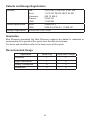
For SPARES, ADVICE or REPAIRS Please call us on 0844 571 5000 (UK Only) MIRA DISCOVERY THERMOSTATIC MIXER Installation and User Guide These instructions are to be left with the user 1 CONTENTS Introduction.............................................................................................. 3 Patents and Design Registration........................................................... 4 Safety : Warnings..................................................................................... 5 Pack Contents.......................................................................................... 7 Specifications........................................................................................... 9 Operating Parameters........................................................................... 9 Installation.............................................................................................. 12 Suitable Plumbing Systems................................................................. 12 General................................................................................................ 12 Installation Methods............................................................................ 14 Exposed Shower Control..................................................................... 15 1. Rear Supplies.................................................................................. 15 2. Rising or Falling Supplies................................................................ 17 Built-in Shower Control........................................................................ 19 1. Solid Wall or Stud Partition (Using Securing Brackets - Mounting off Front Face)................. 19 2. Solid Wall or Stud Partition (Using Rear Fixing Points on Shower Control)........................... 22 3. Laminated Panels (Using Securing Brackets - Mounting off Rear Face).................. 24 Control Assembly................................................................................ 26 Reversed Inlet Supplies......................................................................... 28 Operation................................................................................................ 30 Commissioning...................................................................................... 31 Fault Diagnosis....................................................................................... 32 Maintenance............................................................................................ 33 Spare Parts............................................................................................. 36 Accessories............................................................................................ 38 Notes....................................................................................................... 39 Customer Service................................................................................... 40 2 INTRODUCTION Thank you for purchasing a quality Mira product. To enjoy the full potential of your new product, please take time to read this guide thoroughly, having done so, keep it handy for future reference. The Mira Discovery Thermostatic Mixer is a Thermostatic Shower Control with separate flow and temperature controls. A 12 L/Min flow regulator is supplied for high pressure systems to reduce excessive shower force. Note! The fitting of any flow regulator will invalidate TMV2 compliance due to the minimum flow rate requirements. Do not fit flow regulators in TMV2 applications. The Thermostatic Mixer incorporates a wax capsule temperature sensing unit, which provides an almost immediate response to changes in pressures or temperature of the incoming water supplies to maintain the selected temperature. An adjustable maximum temperature stop is provided which limits the temperature to a safe level. Inlet Filters are fitted to protect the thermostatic cartridge. Mira Discovery Exposed: Thermostatic Mixer for connection to rising, falling or rear entry pipework, supplied complete with Mira Discovery Shower Fittings. Mira Discovery Built-in: Thermostatic Mixer for connection to concealed pipework, supplied complete with Mira Discovery Shower Fittings. Type 2 Valves This product has been certified as a Type 2 valve under the BUILDCERT TMV2 scheme. It also complies with the Water Supply (water fittings) Regulations 1999. Application The approved designations for Type 2 Valves are as follows: Models Designation Mira Discovery HP-S, LP-S Important! The fitting of any flow regulator will invalidate TMV2 compliance due to the minimum flow rate requirements. Do not fit flow regulators in TMV2 applications. If you experience any difficulty with the installation or operation of your new Thermostatic Mixer, please refer to ‘Fault Diagnosis’, before contacting Kohler Mira Ltd. Our telephone and fax numbers can be found on the back cover of this guide. 3 Patents and Design Registration Patents: GB: Euro: Germany: France: USA: 2 291 693, 2 392 225, 2 421 297 1 672 257 DE FR GB IT NL SE 695 13 455.8 0 694 721 7 240 850 Patent Applications: Euro: USA: 03254070.0 2006-0124758-A1, 11/804 631 Design Registration 000351887-0001-0006 Guarantee Mira Showers guarantee the Mira Discovery against any defect in materials or workmanship for a period of five years from the date of purchase. For terms and conditions refer to the back cover of this guide. Recommended Usage Valve Only Valve with Fittings Domestic Application ü ü Light Commercial ü û Heavy Commercial û û Healthcare û û 4 SAFETY : WARNINGS The function of a thermostatic mixing valve is to deliver water consistently at a safe temperature. In keeping with every other mechanism, it cannot be considered as functionally infallible and as such, cannot totally replace a supervisor’s vigilance where that is necessary. Provided it is installed, commissioned, operated and maintained within manufacturers recommendations, the risk of failure, if not eliminated, is reduced to the minimum achievable. Mira thermostatic mixers are precision engineered and should give continued safe and controlled performance, provided: 1. They are installed, commissioned, operated and maintained in accordance with manufacturers recommendations. 2. Periodic attention is given, when necessary, to maintain the product in good functional order. 3. Type 2 Valves are only used for applications covered by their approved designations, refer to the TMV2 Requirements Manual. Caution! 1. Read all of these instructions. 2. Retain this guide for later use. 3. Pass on this guide in the event of change of ownership of the installation site. 4. Make sure that you fully understand how to operate this shower and make sure that it is properly maintained in accordance with the instructions given in this manual. 5. Follow all warnings, cautions and instructions contained in this guide. 6. Do not install the product in a position in which service access is restricted. 7. Anyone who may have difficulty understanding or operating the controls of any shower should be attended whilst showering. Particular consideration should be given to: 7.1. The young. 7.2. The elderly. 7.3. The infirm. 7.4. The disabled. 7.5. Anyone who suffers from a medical condition that can result in temporary incapacity (e.g. Epilepsy or blackouts). 7.6. Anyone inexperienced in the correct operation of the controls. 8. This appliance is not intended for use by persons (including children) with reduced physical, sensory or mental capabilities, or lack of experience and knowledge, unless they have been given supervision or instruction concerning the use of the appliance by a person responsible for their safety. 5 9. Children should be supervised to make sure that they do not play with the appliance. 10. Care is required when adjusting flow or temperature, make sure that the temperature has stabilised. Rapid/excessive movement of the flow and/ or temperature control levers may result in momentary changes in blend temperature. 11. When this product has reached the end of its serviceable life, it should be disposed of in a safe manner, in accordance with current local authority recycling, or waste disposal policy. 6 PACK CONTENTS Tick the appropriate boxes to familiarise yourself with the part names and to confirm that the parts are included. Exposed Discovery Thermostatic Mixer 1 x Mira Discovery Thermostatic Mixer 2 x Concealing Plates 2 x 15 mm Compression Nuts 1 x O-Key 2 x 15 mm Olives 1 x 12 L/Min Flow Regulator 2 x Concealing Caps (Note! see section: Type 2 Valves - Application) 1 x 2.5 mm Hexagon Key 2 x Concealing Cap Seals 2 x Wall Plugs 1 x 24 mm Spanner 1 x Guarantee Registration Document 1 x Installation Template 1 x TMV2 Requirements Manual 2 x Securing Screws 7 Built-in Discovery Thermostatic Mixer 1 x Mira Discovery Thermostatic Mixer 1 x Control Assembly (attached to the Building-in Shroud) 3 x 15 mm Compression Nuts 1 x O-Key 3 x 15 mm Olives 2 x Wall Plugs 1 x 12 L/Min Flow Regulator (Note! see section: Type 2 Valves - Application) 2 x Securing Screws 1 x 2.5 mm Hexagon Key 2 x M5 x 40 Screws 2 x Securing Brackets 1 x Guarantee Registration Document 1 x TMV2 Requirements Manual 8 SPECIFICATIONS Operating Parameters For Type 2 Valves, the supply conditions specified in the TMV2 Requirements Manual take precedence over the operating parameters which follow. Pressures • Max Static Pressure: 10 Bar. • Max Maintained Pressure: 5 Bar. • Min Maintained Pressure (Gravity System): 0.1 Bar. (0.1 bar = 1 Metre head from cold tank base to shower handset outlet). Note! For gravity fed / other low pressure systems (0.5 bar or below) do not fit the flow regulator. For optimum performance supplies should be nominally equal. Flow Regulator Installation Flow regulators are supplied with this product and should be fitted in high pressure systems to either; • Reduce excessive force and flow rate. • Reduce noise through the mixer due to high or unequal pressures. • Stabilise incoming supply temperatures. Important! The fitting of flow regulators will invalidate any TMV2 compliance due to minimum flow rate requirements. Do not fit the flow regulator in TMV2. applications. Temperatures • Factory Pre-set (Blend) Shower: 43°C. • Optimum Thermostatic Control Range: 35°C to 43°C (achieved with supplies of 15°C cold, 65°C hot and nominally equal pressures). • Recommended Hot Supply: 60°C to 65°C Note! The mixing valve can operate at higher temperatures for short periods without damage, however this could detrimentally affect thermostatic performance. For safety and performance reasons it is recommended that the maximum hot water temperature is limited to 65°C. • Cold Water Range: up to 25°C. • Minimum Recommended Differential between Hot Supply and Outlet Temperature: 12°C. 9 Thermostatic Shut-down • For safety and comfort the thermostat will shut off the mixing valve within 2 Seconds if either supply fails (achieved only if the blend temperature has a minimum differential of 12°C from either supply temperature). Connections • Inlets: 15 mm Compression. • Outlet: ½” BSP Flat Face / 15 mm Compression • Standard connections are: hot - left, cold - right, outlet - bottom (EV models), top (BIV models). Flow Rates Typical Flow Rates on Low Pressure Systems - Mira Discovery with Adjustable Fittings or Rigid Head: Typical Flow Rates on High Pressure Systems (with 12 Litres/Min Flow Regulator fitted in shower control outlet) - Mira Discovery with Adjustable Fittings or Rigid Head: 10 Dimensions Exposed Discovery Shower Control 153 131 106 70 Ø56 35 Built-in Discovery Shower Control 20 67 - 85 67 Ø183 Building-in Depth Dimensions in mm 11 INSTALLATION Suitable Plumbing Systems Gravity Fed: The thermostatic mixer must be fed from a cold water cistern (usually fitted in the loft space) and a hot water cylinder (usually fitted in the airing cupboard) providing nominally equal pressures. Mains Pressurised Instantaneous Hot Water System (Combination Boiler): The thermostatic mixer can be installed with systems of this type with balanced pressures. (Recommended Minimum Maintained Pressure: 1.0 Bar). Unvented Mains Pressure System: The thermostatic mixer can be installed with an unvented, stored hot water system. Pumped System: The thermostatic mixer can be installed with an inlet pump (twin impeller). The pump must be installed in a suitable location and in accordance with its instructions. General Installation must be carried out in accordance with these instructions, and must be conducted by designated, qualified and competent personnel. The installation must comply with the requirements of UK Water Regulations/Byelaws (Scotland), Building or any particular regulations and practices, specified by the local water company or water undertakers. Note! Make sure that all site requirements correspond to the information given in section: ‘Specifications’. For Type 2 Valves see also supply conditions in the TMV2 Requirements Manual. 1. 2. 3. 4. 5. 6. 7. The mixer must not be installed in an area where it may freeze. The mixer must be fitted to a tiled or sealed finished surface For stud partitions alternative fixings may be required. Isolating valves must be installed close to the mixer for ease of maintenance. Pipework must be rigidly supported and avoid any strain on the connections. Pipework dead-legs should be kept to a minimum. If pipework enters the shower from the rear through a hole in the wall . Provision must be made to prevent water ingress back into the wall structure. 12 8. The water supplies to this product must be isolated if the product is not to be used for a long period of time. If the product or pipework is at risk of freezing during this period they should also be drained of water. 9. All pipework must be checked for leaks before the product installation is completed. The mixer should be pressurised and the inlet & outlet connections inspected. If the mixer is dismantled during installation or servicing then upon completion the product must be inspected to ensure there are no leaks 10. Decide on a suitable position for the mixer. The position of the mixer and the Shower Fittings must provide a Hose Retaining Ring minimum gap of 25 mm between the spill-over level of the shower tray/bath and the handset (refer to illustration). This is to prevent back-siphonage. For 25 mm Minimum further information on the installation of your Shower Fittings, refer to the Spill-over Level Fittings Installation and User Guide. Note! Only use Shower Fittings recommended by the manufacturer or supplier. 11. Do Not overtighten grubscrews as product damage may occur. Use hexagonal key provided and hand tighten only, do not use power tools. 12. Having completed the installation, make sure that the user is familiar with the operation of the mixer and that this guide is left with the user. 13 Installation Methods Exposed Discovery Shower Control The Exposed Discovery Shower Control can be installed with Rear, Rising or Falling Supply Inlets. For Rear Entry Supplies, go to section: ‘Exposed Shower Control, 1. Rear Supplies’. For Rising or Falling Supplies, go to section: ‘Exposed Shower Control, 2. Rising or Falling Supplies’. Built-in Discovery Shower Control The Built-in Discovery Shower Control can be installed using Rear Fixing Points on the Body, or by using the Securing Brackets (supplied) on the Front Face of a Solid Wall or Stud Partition, or on the Rear Face of a Laminated Panel. For installation into a Solid Wall or Stud Partition using the Securing Brackets, go to section: ‘Built-in Shower Control, 1. Solid Wall or Stud Partition (Using Securing Brackets - Mounting off Front Face)’. Securing Brackets (Front Face) Rear Fixing Points For installation into a Solid Wall or Stud Partition using the Rear Fixing Points, go to section: ‘Built-in Shower Control, 2. Solid Wall or Stud Partition (Using Rear Fixing Points on Shower Control)’. For installation behind a Laminated Panel using the Securing Brackets, go to section: ‘Built-in Shower Control, 3. Laminated Panel (Using Securing Brackets Mounting off Rear Face)’. 14 Securing Brackets (Rear Face) Exposed Shower Control 1. Rear Supplies 1.1 Use the Installation Template to mark the positions of the holes for the Backplate and the pipe centres. Note! Allow a minimum of 150 mm either side of the Shower Control, to allow the hot and cold inlet Compression Nuts to be tightened with the Spanner supplied. 1.2 For solid walls drill the Backplate holes with a 6 mm drill and fit the Wall Plugs (supplied). For other types of wall structure alternative fixings (not supplied) may be required. 1.3 Drill the supply pipe holes at 153 mm centres. 1.4 Recess the wall to allow for the concealing plates, 32 mm diameter x 10 mm deep. 1.5 Fit the supply pipework (Hot - Left, Cold - Right). The pipework must project 18 mm from the finished wall surface at 153 mm centres (use the installation template as a guide). Note! If the connections are reversed, complete the installation then refer to section: ‘Reversed Inlet Supplies’ before commissioning. 1.6 Loosen the Grubscrew with the 2.5 mm hexagon key (supplied) and remove the Backplate from the Shower Control. 1.7 Secure the Backplate to the wall using the Fixing Screws (supplied). Note! The Grubscrew should be at the bottom. 1.8 Fit the Concealing Plates. Note! Apply silicone sealant to the back face of the flange. 15 Template 10 mm depth x Ø32 mm for Concealing Plates Wall Plugs 153 mm Shower Control Backplate 18 mm Securing Screws Grubscrew Concealing Plate Apply Silicone Sealant Caution! It is essential at this point that the supply pipework is thoroughly flushed through before connection to the Shower Control. Failure to do so may result in product malfunction. 1.9 Put the Compression Nuts and Olives onto the pipework. 1.10 Remove the Elbow Shrouds from the Shower Control. 1.11 Align the Shower Control with the pipework and fit onto the Backplate. 1.12Tighten the Compression Nuts onto the Shower Control with the Spanner (supplied). Caution! Take care not to damage the chrome surfaces. 1.13Tighten the Grubscrew to secure the Shower Control to the Backplate. Olive Secure the Control to the Backplate with the Grubscrew Compression Nut Elbow Shrouds 1.14Fit the Shower Fittings, refer to your Fittings Installation and User Guide for instructions. 1.15Turn on the hot and cold water supplies and check for leaks. 1.16Refit the Elbow Shrouds. 1.17The Shower Control is preset to approximately 43 °C at the factory. If adjustment is required, refer to section: ‘Commissioning’. 16 2. Rising or Falling Supplies 2.1 Remove the Elbow Shrouds from the Shower Control. 2.2 Rising Supplies: Loosen the Grubscrew on each Elbow using the 2.5 mm hexagon key (supplied) and pull off the Elbows from the Shower Control. Refit each Elbow on the opposite side and rotate 90° as required. Retighten the Grubscrews. Caution! Do not overtighten. Falling Supplies: Loosen the Grubscrew on each Elbow using the 2.5 mm hexagon key (supplied) and rotate the Elbows 90° as required. Retighten the Grubscrews. Caution! Do not overtighten. 2.3 Use the Installation Template to mark the positions of the fixing holes for the Backplate. Note! Allow a minimum of 150 mm either side of the Shower Control, to allow the hot and cold inlet Compression Nuts to be tightened with the Spanner supplied. 2.4 For solid walls drill the Backplate holes with a 6 mm drill and fit the Wall Plugs (supplied). For other types of wall structure alternative fixings (not supplied) may be required. 2.5 Fit the supply pipework, centres set 35 mm from the finished wall surface (Hot - Left, Cold - Right). Note! If the connections are reversed, complete the installation then refer to section: ‘Reversed Inlet Supplies’ before commissioning. 2.6 Loosen the Grubscrew and remove the Backplate from the Shower Control. 17 Template Cold Supply Wall plugs Hot Supply 2.7 Attach the Backplate to the wall using the Fixing Screws (supplied). Note! The Grubscrew should be at the bottom. Caution! It is essential at this point that the supply pipework is thoroughly flushed through before connection to the Shower Control. Failure to do so may result in product malfunction. 2.8 Fit the Connector Covers and ‘O’ Seals onto the pipework. 2.9 Fit the Compression Nuts and Olives onto the pipework. 2.10Align the Shower Control with the pipework and fit onto the Backplate. 2.11 Tighten the Compression Nuts onto the Shower Control with the Spanner (supplied). Caution! Take care not to damage the chrome surfaces. 2.12Tighten the Grubscrew to secure the Shower Control to the Backplate. 2.13Fit the Shower Fittings, refer to your Fittings Installation and User Guide for Instructions. 2.14Turn on the hot and cold water supplies and check for leaks. 2.15Refit the Elbow Shrouds. 2.16Position the Connector Covers so that they slope away from the wall and slide them down the pipework, until they are flush with the Elbow Shrouds. 2.17The shower control is preset to approximately 43 °C at the factory. If adjustment is required, refer to the section ‘Commissioning’. 18 Securing Screws Backplate Connector cover ‘O’ Seal Compression Nut Olive Secure the Control to the Backplate with the Grubscrew Elbow Shroud Built-in Shower Control 1. Solid Wall or Stud Partition (Using Securing Brackets - Mounting off Front Face) 1.1 Determine the route for the hot and cold supply pipework and for the outlet pipework. When connecting to the BIV Shower Fittings it is recommended that the outlet be positioned above and to one side of the Shower Control. This is to prevent the Flexible Hose from obstructing the Shower Controls. 1.2 Remove the two Securing Screws (retain for later use) and remove the Shower Control from the Building‑in Shroud. 1.3 Mark the position of the Shower Control using the Building-in Shroud as a guide. 1.4 Mark the routes for the hot and cold supply pipework at 108 mm centres. Falling Supplies: For falling supplies loosen the grubscrew on each Elbow using the 2.5 mm Hexagon Key (supplied). Remove the Elbows and install on opposite sides. Secure the Elbows with the Grubscrews. Caution! Do not overtighten. Note! Make sure that the Filter Plugs are positioned to the front (i.e. Hexagonal Key facing forward). 1.5 Mark the route for the outlet pipework. Note! The Outlet Elbow should be sited above the Shower Control and on the right or left, as site dictates. 1.6 Remove the plasterboard and brick work to a minimum depth of 62 mm. 19 Alternative Pipe Layouts Outlet Pipe BIR Outlet Pipe BIV Hot Inlet Outlet Pipe BIV Cold Inlet Shower Control 6 mm Min Finished Wall Finished Wall Surface 62 mm Min 24 mm Max Finished Wall 1.7 Fit the Securing Brackets to the Shower Control. Important! Make sure that the correct holes are used, otherwise the Backplate cannot be fitted. Note! The Securing Brackets can be rotated for suitable fixing points. 1.8 Mark the positions for the Countersunk Fixing Holes on the wall. 1.9 For solid walls drill two 6 mm holes for the Wall Plugs. Caution! Do not drill into pipes in the wall. Backplate Securing Hole Backplate Securing Hole Countersunk Fixing Hole Outlet Pipe to Fittings 1.10Fit the Wall Plugs (supplied) and fix the Shower Control to the wall with the Securing Screws provided. Note! For stud partition installations alternative fixings may be required (not supplied). Securing Screw 1.11Connect the hot and cold supply pipes and tighten the Compression Nuts. Caution! Make sure that the Olives are fitted and all pipework is flushed through before connecting to the Shower Control. 1.12Fit the outlet pipework, leaving enough pipe through the wall to temporarily cap off. 1.13Turn on the water supplies and check for leaks. 20 Rotate for Suitable Fixing Point Cold Supply Hot Supply 1.14Attach the Building-in Shroud to the Shower Control using the two Securing Screws. 1.15Using the ‘Finished Wall Indicator’ on the Building-in Shroud as a guide, finish the wall. Caution! Make sure that the finished wall is within the maximum and minimum limits or the control components will not fit correctly. 1.16Remove the Building-in Shroud. Retain the two Securing Screws for fitting the Backplate. 1.17Fit the Shower Fittings, refer to your Fittings Installation and User Guide for instructions. 1.18Fit the Concealing Plate and Control Assembly, refer to section: ‘Control Assembly’. 21 Maximum / Minimum Limits Min Finished Wall Surface Finished Wall Max Finished Wall Surface Max Min F9802 2. Solid Wall or Stud Partition (Using Rear Fixing Points on Shower Control) 2.1 Refer to section: ‘1. Solid Wall or Stud Partition (Using Securing Brackets - Mounting off Front Face)’ and follow steps 1.1 to 1.4. 2.2 Cut away the plasterboard or brick work to the required depth. Important! This depth ‘X’ will depend on the finished wall thickness e.g. tiles or facia board. Refer to the table for this measurement. For stud partitions depth ‘X’ refers to the distance from the rear mounting e.g. timber noggin, to the front of the wall (before tiling). Finished Wall Surface Finished Wall Thickness Depth ‘X’ Rear Support Finished Wall Thickness (e.g. tile and adhesive) 4 mm 6 mm 8 mm 10 mm 12 mm 14 mm 16 mm 18 mm 20 mm 22 mm 24 mm Wall Cutout Depth ‘X’ 81 - 63 mm 79 - 61 mm 77 - 59 mm 75 - 57 mm 73 - 55 mm 71 - 55 mm 69 - 55 mm 67 - 55 mm 65 - 55 mm 63 - 55 mm 61 - 55 mm Important! Total building-in depth ( X + Finished Wall Thickness) must not exceed an absolute maximum of 85mm. 22 2.3 Mark the positions of the Fixing Screw holes on the wall. 2.4 For solid walls drill two 6 mm holes for the Wall Plugs. 2.5 Insert the Wall Plugs (supplied) and attach the Shower Control to the wall with the Securing Screws provided. Note! For stud partition installations alternative fixings may be required (not supplied) to fix the shower control to the rear face of the wall cavity or to a timber noggin. 2.6 Refer to section: ‘1. Solid Wall or Stud Partition (Using Securing Brackets - Mounting off Front Face)’ and follow steps 1.10 to 1.18. Rear Fixing Point Securing Screw Cold Supply Hot Supply 23 Outlet Pipe to Fittings 3. Laminated Panels (Using Securing Brackets - Mounting off Rear Face) Note! For laminated panels the shower control must be positioned from the rear of the panel. Panel thickness must be between 4 and 12 mm (if a thicker panel is used, it will be necessary to recess the securing brackets into the rear of the panel). Important! Make sure that there is a minimum clearance of 64 mm behind the laminated panel to house the shower control. 3.1 Remove the two Securing Screws (retain for later use) and remove the Shower control from the Building‑in Shroud. 3.2 Mark the position of the Shower Control using the Building-in Shroud as a guide. 3.3Carefully cut out the laminated panel. 3.4 Fit the Securing Brackets to the Shower Control. Important! The brackets must be fixed vertically, as illustrated. Important! Make sure that the correct holes are used, otherwise the Backplate cannot be fitted. 3.5 Position the Shower Control on the front of the panel and mark the position of the M5 fixing holes. Important! Make sure that the correct holes are used (refer to illustration). Note! Make sure that the Filter Plugs are positioned so that they can be removed for servicing. 3.6 Drill the two 5 mm holes for the fixing positions (countersink the holes at the front). 3.7 Secure the Shower Control with the M5 x 40 screws as shown. 24 Backplate Securing Hole M5 Fixing Hole Filter Plugs Backplate Securing Hole M5 Fixing Hole M5 x 40 mm Fixing Screw 3.8 Fit the hot and cold supply pipes and tighten the compression nuts. Falling Supplies: For falling supplies loosen the grubscrew on each Elbow using the 2.5 mm Hexagon Key (supplied). Remove the Elbows and install on opposite sides. Secure the Elbows with the Grubscrews. Caution! Do not overtighten. Note! Make sure that the Filter Plugs are positioned to the front (i.e. Hexagonal Key facing forward). Caution! Make sure that the olives are fitted and all pipework is flushed through before connecting to the Shower Control. 3.9 Fit the outlet pipework, leaving enough pipe through the wall to temporarily cap off. 3.10Turn on the water supplies and check for leaks. 3.11Fit the Shower Fittings, refer to your Fittings Installation and User Guide for instructions. 3.12Fit the Concealing Plate and Control Assembly, refer to section: ‘Control Assembly’. 25 Outlet Pipe to Fittings Hot Supply Cold Supply Control Assembly Important! The Yellow lugs on the Flow Control must be in the fully clockwise (off) position in order to fit the Control Assembly. Note! The Flow Control Lugs on pre 2006 models are Black. 1. Rotate the Temperature Knob fully clockwise and carefully pull it off. 2. Remove the Grey Control Bearing. 3. Pull off the Flow Lever. 4. Remove the Flow Lever Adapter. Important! The Lever Retainer must not be removed. Flow Control ‘Yellow Lugs’ Backplate Lever Retainer Flow Lever Adapter 5. Carefully unclip the Concealing Plate from the Backplate. Note! Use a screwdriver in the cutout to assist separation. 6. Fit the Backplate to the Shower Control and secure with the two Securing Screws (removed from the Building-in Shroud). Make sure that the Foam Seal is fully compressed. Do not overtighten. 7. With the cutout at the bottom, locate the Concealing Plate over the Shower Control, engage the crosses in the Concealing Plate with the square recesses in the Backplate, and push firmly until the Concealing Plate clicks into position. 26 Concealing Plate Flow Lever Grey Control Bearing Temperature Knob Note! If the knob does not come off, rotate it fully anticlockwise, pull on the Temperature Knob while slowly rotating it clockwise until it disengages. 8. 9. Align the Green Temperature Hub with the Lever Retainer Clips as illustrated. Slide the Flow Lever Adapter over the Cartridge and onto the yellow lugs on the Flow Control, exactly as illustrated. 10. Push the Flow Lever onto the Flow Lever Adapter (align lugs as illustrated). 11. Push the Grey Control Bearing over the Lever Retainer. Note! Align the Grey Control Bearing with the Lever Retainer Clips and not the Flow Control Lever. 12. Refer to section ‘Commissioning’, for maximum temperature setting and temperature knob assembly. 27 Green Temperature Hub Lever Retainer Clips Flow Lever Adapter Flow Lever Lever Retainer Clips Grey Control Bearing REVERSED INLET SUPPLIES The Discovery Shower Control is supplied with inlet connections Hot-Left, Cold‑Right and Bottom-Outlet as standard. If the hot and cold water supply pipes have been reversed during installation the following procedure must be performed. 1. Isolate the hot and cold water supplies. 2. Operate the Flow Lever and Temperature Knob to drain any residual water. 3. Rotate the Temperature Knob fully clockwise and carefully pull it off. Note! If the knob does not come off, rotate it fully anticlockwise, pull on the Temperature Knob while slowly rotating it clockwise until it disengages. 4. Remove the Grey Control Bearing. 5. Pull off the Flow Lever. 6. Remove the Flow Lever Adapter. 7. Exposed Models only (illustrated): a) Carefully remove the Locking Ring. b) Rotate the Lever Retainer clockwise to disengage and remove. 8. Built-in Models only: a) Carefully unclip the Concealing Plate from the Backplate. Important! The Lever Retainer must not be removed. Note! Use a screwdriver in the cutout to assist separation. b) Unscrew the two Securing Screws and carefully remove the Backplate from the Shower Control. 9. Fit the ‘O’ Key over the Green Temperature Hub and onto the Brass Nut. 10. Turn the ‘O’ Key anticlockwise to unscrew the Cartridge from the Body and pull the Cartridge clear. ‘O’ Key Lever Retainer Locking Ring Important! Do not remove for Built-in Model Grey Control Bearing Flow Lever Adapter Flow Lever Temperature Knob 28 11. Rotate the Cartridge 180° to reverse the inlets to the Cartridge. Caution! Make sure the two Cartridge Side Seals are not damaged. 12. Refit the Cartridge into the Shower Control Body, make sure that the lugs engage in the slots in the Body. Note! To assist in refitting the Cartridge, rotate 45° (i.e. with the inlet seals at 2 and 8 o’clock) and push into the Shower Control, then rotate to align the lugs with the slots in the body and push fully home (refer to illustration). Important! Make sure that the side seals do not extrude from the Shower Control Body when pushing the cartridge in. Damage to these seals will result in a leak from the shower outlet. Cartridge Lugs Slots Carefully push the Cartridge into the Shower Control Body and rotate. 13. Tighten the Brass Nut using the ‘O’ Key (supplied). 14. Remove the ‘O’ Key. Note! If the ‘O’ Key has become trapped under the Yellow lugs on the Flow Control, rotate them until the ‘O’ Key can be removed. Note! The Flow Control Lugs on pre 2006 models are Black. Caution! Make sure that the Yellow Lugs are returned to the fully clockwise position before restoring the water supplies. 15. Restore the hot and cold water supplies and check for leaks. 16. Exposed Models Only: a) Fit the Lever Retainer with the clips horizontal, make sure both sides locate under the lip and rotate anticlockwise. b) Fit the Locking Ring. 17. Built-in Models only: a) Fit the Backplate to the Shower Control and secure with the two Securing Screws. Make sure that the Foam Seal is fully compressed. b) With the cutout at the bottom, slide the Concealing Plate over the Shower Control, engage the crosses in the Concealing Plate with the square recesses in the Backplate, and push firmly until the Concealing Plate clicks into position. 18. Refer to the section ‘Installation, Control Assembly’ and follow steps 8 to 12. 29 OPERATION Shower Control (Exposed and Built-in Controls) Note! The shower performance may be effected if other water appliances are operated whilst the shower is in use. Turn the Flow Lever Anticlockwise to the Preset Maximum Flow OFF Turn the Temperature Control Knob Clockwise to decrease the Temperature, or Anticlockwise to the Preset Maximum Temperature ON Sunburn or skin conditions can increase your sensitivity to hot water. Make sure that you set the shower to a cooler temperature. Caution! Do not force the Temperature Control Knob. If the desired temperature cannot be achieved refer to the section ‘Commissioning’. 30 COMMISSIONING The Thermostatic Shower Control is preset to approximately 43 °C at the factory. If adjustment is required, set the maximum temperature as follows: For Type 2 installations the maximum blend temperature is determined by the application, refer to the TMV2 Requirements Manual. Flow Rate Note! Make sure that any inlet isolating valves are fully open. If excessive flow rate is experienced from the Shower Control, install the supplied Flow Regulator, refer to the Discovery Fittings Installation and User Guide. Important! The fitting of any flow regulator will invalidate TMV2 compliance due to the minimum flow rate requirements. Do not fit flow regulators in TMV2 applications. Setting the Maximum Temperature 1. Rotate the Temperature Control Knob fully clockwise (full cold position) and carefully pull it off. Note! If the knob does not come off, rotate it fully anticlockwise, pull on the Temperature Knob while slowly rotating it clockwise until it disengages. Green 2. Turn the Green Temperature Hub fully Temperature anticlockwise (full hot position). Hub 2.5 mm Note! Operate the Shower Control until Hexagon the hot and cold water temperatures have Key stabilised. 3. Insert the 2.5 mm Hexagon Key into the centre of the Green Temperature Hub. 4. Turn the 2.5 mm Hexagon Key anticlockwise to increase the temperature, or clockwise to decrease temperature. 5. Rotate the Green Temperature Hub fully clockwise (refer to the following illustration). 6. Position the Temperature Control Knob (refer to the following illustration) over the Green Temperature Hub and gently push it on. Note! Make sure the Temperature Control Knob moves freely to full hot and to full cold. Rotate the Green Temperature Hub, fully clockwise to this position The Temperature Control Knob must be in this position (the full cold position) over the Green Temperature Hub 31 FAULT DIAGNOSIS Symptom 1. Cause / Rectification Only hot or cold a. water from the mixer outlet. b. c. d. e. 2. F l u c t u a t i n g o r a. reduced flow rate. b. Inlets reversed (hot supply to cold supply). Refer to section: ‘Reversed Inlet Supplies’. No hot water reaching the mixer. Check the filters for any blockage. Installation conditions outside operating parameters: refer to sections: ‘Specifications’ and ‘Commissioning’. If you have a combination type boiler it may not be producing sufficiently hot water at desired flow rate (refer to ‘Specifications’). Fit flow regulator (supplied) to shower valve outlet. For more information contact Mira Showers or visit the website. d. e. Check the showerhead, hose and filters for any blockage. Make sure the maintained inlet pressures are nominally balanced and sufficient, refer to section: ‘Specifications’. Make sure the inlet temperature differentials are sufficient, refer to section: ‘Specifications’. Flow regulator fitted incorrectly. Airlock or partial blockage in pipework. 3. No flow from the a. mixer outlet. b. Check the showerhead, hose and filters for any blockage. Hot or cold supply failure. 4. Blend temperature a. drift. b. c. d. Refer to symptom 2. above. Significant supply temperature fluctuation. Significant supply pressure fluctuation. Faulty thermostatic cartridge, renew. 5. M a x i m u m b l e n d a. temperature setting too hot or too cold. b. Indicates incorrect maximum temperature setting; refer to section: ‘Commissioning’. Refer to symptom 4. above. 6. Water leaking from a. the Showerhead. b. Normal for a short period after shut off. Check that the pressures are not in excess of the specifications for product. Cartridge inlet seals damaged, renew. Renew the thermostatic Cartridge. c. c. d. 7. Flow rate too low or a. too high. b. c. (low) Insufficient supply pressures. (high) Supply pressure too high. Install flow reg. Refer to symptom 2. above. 32 MAINTENANCE General The Mira Discovery Shower Control is designed to be maintenance free, as such there are no serviceable parts in the cartridge. However regular cleaning will keep the shower in pristine condition, refer to section: ‘Maintenance, Cleaning’. Filters are fitted to the inlets of the mixer to protect the cartridge and will give many years of trouble free showering. Filters should be checked at yearly intervals and cleaned or replaced to maintain optimum shower performance. Refer to the section ‘Maintenance, Filters’. If you require a Mira trained engineer or agent, refer to the section ‘Customer Service’. Lubricants Silicone-only based lubricants can be used to assist in refitting. Caution! Oil based or other lubricant types, may cause rapid deterioration of seals. Cleaning Warning! Many household cleaners contain abrasives and chemical substances, and should not be used for cleaning plated or plastic fittings. These finishes should be cleaned with a mild washing up detergent or soap solution, and then wiped dry using a soft cloth. Do not use descalents on this product. In-service Tests The principal means for determining the continuing satisfactory performance of the mixing valve is the in-service test, refer to the TMV2 Requirements Manual. Frequency of In-service Tests - Commercial (non-domestic installations) Check for correct blend setting every 6 months. 33 Filters - Exposed Models To clean or replace the inlet filters: 1. Isolate the hot and cold water supplies. 2. Operate the Flow Lever to drain any residual water. 3. Remove the Elbow Shrouds. 4. Unscrew the Filter Caps with the ‘O’ key (supplied) or a 12 mm hexagonal ‘O’ Key key. 5. Remove the Elbow Retaining Clips. 6. Carefully pull out the Inlet Filters. 7. Clean each filter in turn under a jet of water to remove any lodged particles. 8. Refit the Inlet Filters. 9. Refit the Elbow Retaining Clips and tighten the Filter Caps. Caution! Make sure that the Elbow Retaining Clips are fitted vertically as illustrated, otherwise the Elbow Shrouds will not fit correctly. 10. Restore the hot and cold water supplies and check for leaks. 11. Refit the Elbow Shrouds. Inlet Filter Elbow Retaining Clip ‘O’ Seal Filter Cap Elbow Retaining Clip 34 Filters - Built-in Models To clean or replace the inlet filters: Note! Refer to the section ‘Installation, Control Assembly’ for illustrations. 1. Isolate the hot and cold water supplies. 2. O p e r a t e t h e F l o w L e v e r a n d Temperature Knob to drain any residual water. 3. Rotate the Temperature Control Knob ‘O’ Key fully clockwise and carefully pull it off. Note! If the knob does not come Filter off, rotate it fully anticlockwise, pull ‘O’ Seal on the Temperature Knob while Filter Cap slowly rotating it clockwise until it disengages. 4. Remove the Grey Control Bearing. 5. Pull off the Flow Lever. 6. Remove the Flow Lever Adapter. 7. Carefully remove the Concealing Plate Assembly. Important! The Lever Retainer must not be removed. Note! Use a screwdriver in the cutout to assist in the separation. 8. Unscrew the two Securing Screws and carefully remove the Backplate from the Shower Control. 9. Unscrew the Filter Caps with the ‘O’ Key (supplied) or a 12 mm hexagonal key. 10. Using pliers, carefully pull out the Inlet Filters. 11. Clean each Filter in turn under a jet of water to remove any lodged particles. 12. Refit the Filters. 13. Refit and tighten the Filter Caps. 14. Restore the hot and cold water supplies and check for leaks. 15. Fit the Backplate to the Shower Control and secure with the two Securing Screws. Make sure that the Foam Seal is fully compressed. Do not overtighten. 16. With the cutout at the bottom, slide the Concealing Plate over the Shower Control, engage the crosses in the Concealing Plate with the square recesses in the Backplate, and push firmly until the Concealing Plate clicks into position. 17. Refer to the section ‘Installation, Control Assembly’ and follow steps 8 to 12. 35 SPARE PARTS Exposed Thermostatic Shower Control 090 95 Pipe Concealing Plates 1595 036 Temperature Hub Assembly 1595 037 Handle Pack 1595 038 Handle Adapter Pack 1595 039 Cartridge Assembly Pack (also includes components identified ‘D’) 1595 040 Body Trim 1595 041 Elbow Shroud Pack (Identified ‘A’) 1595 042 Elbow Pack Assembly (Identified ‘B’) 1595 043 Mounting Assembly Pack 1595 045 Outlet Nipple Pack 1595 047 Seal Pack (Identified ‘C’) 1595 048 Component Pack 1595 065 Filter (2 off) 1595 231 ‘O’ Key 1595 232 24 mm Spanner 090 95 B A 1595 040 1595 043 090 95 A B B, D A B C B B 1595 065 1595 039 D B B C 1595 045 1595 040 1595 036 1595 065 1595 038 C 1595 231 1595 037 A 1595 232 1595 048 36 Built-in Thermostatic Shower Control 1595 036 Temperature Hub Assembly 1595 037 Handle Pack 1595 038 Handle Adapter Pack 1595 039 Cartridge Assembly Pack (Also includes components identified ‘B’) 1595 044 Concealing Plate Assembly 1595 067 Screw Pack (Identified ‘A’) 1595 070 Component Pack 1595 149 Outlet Nipple Pack 1595 231 ‘O’ Key 1595.283 Building-in Shroud 1609.046 Filter Pack x 2 (identified ‘B’) 1651.138 Seal Pack (Identified ‘C’) 1651.167 Elbow Assembly (pair) 1595.283 1651.167 1595 149 A B C C 1595 039 A A C 1595 038 1595 036 1595 039 1595 044 1595 231 1595 037 1595 070 37 ACCESSORIES Genuine Mira accessories can be purchased direct from Customers Services (our contact details can be found on the back cover of this guide) or from approved stockists or merchants. Eco Showerhead White - 2.1668.001 Chrome - 2.1668.002 The Eco shower head gives you an invigorating shower, but reduces water consumption and heating costs. Everclear Showerhead White - 2.1616.030 Chrome - 2.1616.031 Mira's new Everclear range has been specially designed for hard water areas and reduces the risk of lime scale build up. Logic Showerhead Holder White - 2.1605.149 White/Chrome - 2.1605.150 An alternative to the traditional slide bar. Often a useful addition when positioned for the smaller members of the family. Wall Mounted Soap Dish White - 1.1540.278 Chrome - 1.1540.279 Wall mounted for use anywhere in, or outside the showering area. Double Outlet Check Valve (DCV-H) Chrome - 1.0.110.55.1 An outlet double check valve, designed to prevent the back flow or back-siphonage of potentially contaminated water, through shower controls which are fitted with a flexible shower hose as part of the outlet shower fitting. Mira Standard Grab Bars 300 mm - 2.1605.070 450 mm - 2.1605.071 600 mm - 2.1605.072 Premium grade, highly polished, stainless steel grab bars. Note! Must be installed onto a solid wall. Shower Seat White - 2.1536.128 White/Chrome - 2.1536.129 For use in or out of the showering area. Folds up when not in use. Maximum User Weight - 127 kg (20 stone) Note! Must be installed onto a solid wall. Premium Shower Seat White/Chrome - 2.1731.001 Grey/Chrome - 2.1731.002 Stylish, slim-line and robust shower seat for use in or outside of the shower area. Folds up when not in use. Maximum User Weight - 150 kg (23.5 stone) Note! Must be installed onto a solid wall. 38 NOTES 39 CUSTOMER SERVICE Guarantee Your product has the benefit of our manufacturer’s guarantee which starts from the date of purchase. To activate this guarantee, please return your completed registration card, visit our website or free phone 0800 0731248 within 30 days of purchase (UK only). Within the guarantee period we will resolve defects in materials or workmanship, free of charge, by repairing or replacing parts or product as we may choose. This guarantee is in addition to your statutory rights and is subject to the following conditions: ● The guarantee applies solely to the original installation under normal use and to the original purchaser only. The product must be installed and maintained in accordance with the instructions given in this user guide. ● Servicing must only be undertaken by us or our appointed representative. Note! if a service visit is required the product must be fully installed and connected to services. ● Repair under this guarantee does not extend the original expiry date. The guarantee on any replacement parts or product ends at the original expiry date. ● For shower fittings or consumable items we reserve the right to supply replacement parts only. The guarantee does not cover: ● Call out charges for non product faults (such as damage or performance issues arising from incorrect installation, improper use, inappropriate cleaning, lack of maintenance, build up of limescale, frost damage, corrosion, system debris or blocked filters) or where no fault has been found with the product. ● Water or electrical supply, waste and isolation issues. ● Compensation for loss of use of the product or consequential loss of any kind. ● Damage or defects caused if the product is repaired or modified by persons not authorised by us or our appointed representative. ● Routine maintenance or replacement parts to comply with the requirements of the TMV 2 or TMV 3 healthcare schemes. ● Accidental or wilful damage. ● Products purchased ex-showroom display. Helpdesk Service - Ring our Customer Services Team for product advice, to purchase spare parts or accessories or to set up service visit. You can contact us via phone or e-mail, details below. Please provide your model name, power rating (if applicable) and date of purchase. Mira Showers Website (www.mirashowers. co.uk) Visit our website to register your guarantee, download user guides, diagnose faults, purchase our full range of accessories and popular spares, or request a service visit. Spares and Accessories - We hold the largest stocks of genuine Mira spares and accessories. Contact us for a price or visit our website to purchase items from our accessory range and popular spares. Service/Repairs - No one knows our products better than our nationwide team of Service Technicians. We can carry out service or repair work to your product both during and after the guarantee period. Ask about our fixed price service repairs. To Contact Us: UK 0844 571 5000 Fax: 01 242 282595 E-mail: Visit www.mirashowers.co.uk/ contactus Mira Customer Services Dept, Cromwell Road, Cheltenham, Gloucestershire, GL52 5EP To Contact Us: Eire Only 01 531 9337 What to do if something goes wrong If your product does not work correctly refer to this manual for fault diagnosis and check that it is installed and commissioned in accordance with our instructions. If this does not resolve the issue, contact us for help and advice. E-mail: CustomerServiceEire@ mirashowers.com Extended Guarantees A selection of protection plans are available that enable you to cover repair bills (excludes Eire). Ring 01922 471763 for more details. Mira is a registered trade mark of Kohler Mira Limited. The company reserves the right to alter product specifications without notice. 1087464-W2-F (B92A) FM 14648 40 © Kohler Mira Limited, March 2013