1
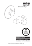
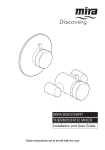
MIRA DISCOVERY SHOWER VALVE Installation and User Guide These instructions are to be left with the user 1 CONTENTS Introduction ............................................................................................. 3 Safety : Warnings .................................................................................... 3 Pack Contents ......................................................................................... 4 Dimensions ............................................................................................. 6 Specifications .......................................................................................... 7 Installation Requirements ...................................................................... 9 Installation ............................................................................................. 11 General .............................................................................................. 11 Installation Methods ........................................................................... 12 Exposed Shower Control ...................................................................... 13 1. Rear Supplies ................................................................................ 13 2. Rising or Falling Supplies ............................................................... 15 Built-in Shower Control ........................................................................ 17 1. Solid Wall or Stud Partition (Using Securing Brackets - Mounting off Front Face) ................. 17 2. Solid Wall or Stud Partition (Using Rear Fixing Points on Shower Control) ............................ 20 3. Laminated Panels (Using Securing Brackets - Mounting off Rear Face) .................. 22 Control Assembly ................................................................................. 24 Reversed Supplies ................................................................................ 25 Commissioning ..................................................................................... 27 Operation ............................................................................................... 28 Fault Finding ......................................................................................... 29 Maintenance .......................................................................................... 30 General .............................................................................................. 30 Lubricants .......................................................................................... 30 Cleaning ............................................................................................. 30 In-service Tests ................................................................................. 30 Frequency of In-service Tests ........................................................... 30 Filters ................................................................................................ 32 Type 2 Valves ........................................................................................ 34 Spare Parts ............................................................................................ 38 Customer Service .................................................................................. 40 2 INTRODUCTION The Discovery Thermostatic Shower Control with independent selection for temperature and spray force. Mira Discovery Exposed: Shower control for connection to rising, falling or rear entry pipework. Mira Discovery Built-in: Shower control for connection to concealed pipework. This product has been certified as a Type 2 valve under the BUILDCERT TMV2 scheme. This product also complies with the water supply (water fittings) regulations 1999. SAFETY : WARNINGS This Discovery Thermostatic Shower Control is precision engineered and should give continued safe and controlled performance, provided: 1. It is installed, commissioned, operated and maintained in accordance with manufacturers recommendations. 2. Periodic attention is given, when necessary, to maintain the product in good functional order. Caution! 1. Read all of these instructions. 2. Retain this guide for later use. 3. Pass on this guide in the event of change of ownership of the installation site. 4. Follow all warnings, cautions and instructions contained in this guide. 5. Anyone who may have difficulty understanding or operating the controls of any shower should be attended whilst showering. Particular consideration should be given to the young, the elderly, the infirm or anyone inexperienced in the correct operation of the controls. 6. When this product has reached the end of it’s serviceable life, it should be disposed of in a safe manner, in accordance with current local authority recycling, or waste disposal policy. If you experience any difficulty with the installation or operation of your new shower control, then please refer to "Fault Diagnosis", before contacting Kohler Mira Limited. Our telephone and fax numbers can be found on the back cover of this guide. 3 PACK CONTENTS 9 Tick the appropriate boxes to familiarize yourself with the Discovery Shower Control part names and to confirm that all the parts are included. Exposed Discovery Shower Control 1 x Shower Control 2 x Concealing Plates 2 x 15 mm Compression Nuts 1 x O-Key 2 x Concealing Caps 2 x Concealing Cap Seals 2 x 15 mm Olives 1 x Flow Regulator (12 litres per minute) 1 x 2.5 mm Hexagon Key 2 x Wall Plugs 1 x 24 mm Spanner 1 x Customer Support Card 1 x Installation Template 4 2 x Securing Screws Built-in Discovery Shower Control 1 x Shower Valve attached to the Building-in Shroud 1 x Control Assembly 1 x O-Key 3 x 15 mm Compression Nuts 3 x 15 mm Olives 2 x Wall Plugs 1 x Flow Regulator (12 litres per minute) 2 x Securing Screws 2 x M5 x 40 Screws 1 x 2.5 mm Hexagon Key 2 x Securing Brackets 1 x Customer Support Card 5 DIMENSIONS Exposed Discovery Shower Control 153 131 106 70 Ø56 35 Built-in Discovery Shower Control 30 67 - 85 Building-in Depth 67 Ø183 Dimensions in mm 6 SPECIFICATIONS Operating Parameters For Type 2 valves, the supply conditions specified in section: 'Type 2 Valves Application' take precedence over the operating parameters which follow. Pressures Maximum Static Pressure: 10 Bar. Maximum Maintained Pressure: 5 Bar. Minimum Maintained Pressure (Gas Water Heater): 1.0 Bar. Note! For optimum performance the inlet pressures should be nominally equal and should not exceed 5:1, in favour of either supply, during flow. Minimum Maintained Pressure (Gravity System): 0.1 Bar. (0.1 bar = 1 Metre head from base of cold tank to the outlet of the shower handset) Temperatures Factory Pre-set Shower Blend Temperature: 43 °C. Optimum Thermostatic Control Range: 35 °C - 45 °C. (Achieved with supplies of 15 °C cold, 65 °C hot and nominally equal pressures). Maximum Hot Supply: 85 °C. Recommended Hot Supply: 60 °C - 65 °C. Minimum Differential between Hot Supply and set Blend Temperature: 10 °C. Cold Water Range: 1 °C - 20 °C. Note! BS:6700 recommends that the temperature of stored hot water should never exceed 65 °C. A temperature of 60 °C is considered sufficient to meet all normal requirements and will minimise the deposition of scale in hard water areas. Connections Standard connections are: Hot-Left, Cold-Right, Bottom Outlet (Exposed), Top Outlet (Built-in). If reversed inlets are required refer to sections: ‘Installation’ and ‘Reversed Supplies’. Inlets: 15 mm Compression. Outlet: Exposed = 1/2” BSP Flat Face, Built-in = 15 mm Compression. Thermostatic Shut-down Thermostat will shut off the Hot Supply within 2 seconds if the Cold Supply Fails. (Achieved only if the hot supply temperature is greater than 10 °C above the set blend temperature). 7 Flow Rates Typical Flow Rates on Low Pressure Systems - Mira Discovery with Adjustable Fittings or Rigid Head: Typical Flow Rates on High Pressure Systems (with 12 Litres/Min Flow Regulator fitted in shower control outlet) - Mira Discovery with Adjustable Fittings or Rigid Head: 8 INSTALLATION REQUIREMENTS Key to symbols Isolating valve Twin Impeller Pump Mixing Valve Single Impeller Pump Overflow Indicator Tempering Valve Pressure Reducing Valve Mini Expansion Vessel Note! The Shower Control is compatible with the following installations. Gravity fed system The shower MUST be fed from a cold water cistern and hot water cylinder providing nominally equal pressure. Note! A minimum head of 1 Metre is required from the bottom of the cold water feed tank to the handset. 1m Min Gas heated system The shower MUST be installed with a ed nd gas water heater or combination boiler e m of a fully modulating design. m Note! Flow regulator recommended co to be e R installed, refer to the ‘Discovery Fittings r o t Guide’. However, Installation and User a l it is possible following installation of a gu e flow regulator R that the flow rate is reduced w too much for the boiler to ignite. If this is Fthelocase remove the flow regulator. 9 Unvented mains pressure system The shower can be installed with a ed unvented, stored hot water cylinder. nd w o l F r o t la u g e R e m om c Re Mains pressurised instantaneous hot water system (thermal store) d The shower can be installed with de n systems of this type with balanced e m pressures. m co to be Note! Flow regulator recommended e R installed, refer to ther‘Discovery Fittings o t Installation Manual’. la w o l F gu e R Pumped system The shower can be installed with an inlet pump (twin impeller). The pump must be ed nd installed on the floor next to the hot water e m cylinder. m Note! Flow regulator recommended co to be e R installed, refer to ther‘Discovery Fittings o Installation Manual’. at w o l F l u g Re 90° 30°-60° Air Separation 10 INSTALLATION General Installation must be carried out in accordance with these instructions, and must be conducted by designated, qualified and competent personnel. The installation must comply with the “Water Supply Regulations 1999 (Water Fittings)” or any particular regulations and practices, specified by the local water company or water undertakers. Note! Make sure that all site requirements correspond to the information given in the section: ‘Specifications’. For Type 2 valves see also supply conditions in section: 'Type 2 Valves'. 1. Caution! The shower must not be installed in an area where it may freeze. 2. A distance of at least 150 mm is required between any side walls and both the hot and cold inlets to allow access for tightening the inlet compression nuts. 3. For stud partitions alternative fixings (not supplied) may be required. 4. Isolating valves must be installed close to the Shower Control for ease of maintenance. 5. Pipework must be rigidly supported and avoid any strain on the connections. 6. Pipework dead-legs should be kept to a minimum. 7. Supply pipework layout should be arranged to minimise the effect of other outlet usage upon the dynamic pressures at the valve inlets. Note! This is particularly important for gravity fed installations. 8. Inlet and outlet threaded joint connections should be made with PTFE tape or liquid sealant. Do not use oil-based, non-setting joint compounds. 9. To eliminate pipe debris it is essential that supply pipes are thoroughly flushed through before final connection. 10. Decide on a suitable position for the shower control. The position of the shower control and the shower fittings must provide a minimum gap of 25 mm between the spill-over level of the shower tray/bath and the handset. This is to prevent back-siphonage. For further information on the installation of your shower fittings, refer Hose Retaining Ring to the Discovery Fittings Installation and User Guide. Note! Only use shower fittings 25 mm Minimum recommended by the manufacturer or supplier. Spill-over Level 11 Installation Methods Exposed Discovery Shower Control The Exposed Discovery Shower Control can be installed with Rear, Rising or Falling Supply Inlets. For Rear Entry Supplies, go to section: ‘Exposed Shower Control, 1. Rear Supplies’. For Rising or Falling Supplies, go to section: ‘Exposed Shower Control, 2. Rising or Falling Supplies’. Built-in Discovery Shower Control The Built-in Discovery Shower Control can be installed using Rear Fixing Points on the Body, or by using the Securing Brackets (supplied) on the Front Face of a Solid Wall or Stud Partition, or on the Rear Face of a Laminated Panel. For installation into a Solid Wall or Stud Partition using the Securing Brackets, go to section: ‘Built-in Shower Control, 1. Solid Wall or Stud Partition (Using Securing Brackets - Mounting off Front Face)’. Securing Brackets (Front Face) Rear Fixing Points For installation into a Solid Wall or Stud Partition using the Rear Fixing Points, go to section: ‘Built-in Shower Control, 2. Solid Wall or Stud Partition (Using Rear Fixing Points on Shower Control)’. For installation behind a Laminated Panel using the Securing Brackets, go to section: ‘Built-in Shower Control, 3. Laminated Panel (Using Securing Brackets Mounting off Rear Face)’. 12 Securing Brackets (Rear Face) Exposed Shower Control 1. Rear Supplies 1.1 Use the Installation Template to mark the positions of the holes for the Backplate and the pipe centres. Note! Allow a minimum of 150 mm either side of the Shower Control, to allow the hot and cold inlet Compression Nuts to be tightened with the Spanner supplied. 1.2 For solid walls drill the Backplate holes with a 6 mm drill and fit the Wall Plugs (supplied). For other types of wall structure alternative fixings (not supplied) may be required. 1.3 Drill the supply pipe holes at 153 mm centres. 1.4 Recess the wall to allow for the concealing plates, 32 mm diameter x 10 mm deep. 1.5 Fit the supply pipework (Hot - Left, Cold - Right). The pipework must project 18 mm from the finished wall surface at 153 mm centres (use the installation template as a guide). Note! If the connections are reversed, complete the installation then refer to section: ‘Reversed Inlet Supplies’ before commissioning. 1.6 Loosen the Grubscrew with the 2.5 mm hexagon key (supplied) and remove the Backplate from the Shower Control. 1.7 Secure the Backplate to the wall using the Fixing Screws (supplied). Note! The Grubscrew should be at the bottom. 1.8 Fit the Concealing Plates. Note! Apply silicone sealant to the back face of the flange. 13 Template 10 mm depth x Ø32 mm for Concealing Plates Wall Plugs 153 mm Shower Control Backplate 18 mm Securing Screws Grubscrew Concealing Plate Apply Silicone Sealant 1.9 1.10 1.11 1.12 1.13 Caution! It is essential at this point that the supply pipework is thoroughly flushed through before connection to the Shower Control. Failure to do so may result in product malfunction. Put the Compression Nuts and Olives onto the pipework. Remove the Elbow Shrouds from the Shower Control. Align the Shower Control with the pipework and fit onto the Backplate. Tighten the Compression Nuts onto the Shower Control with the Spanner (supplied). Caution! Take care not to damage the chrome surfaces. Tighten the Grubscrew to secure the Shower Control to the Backplate. Olive Secure the Control to the Backplate with the Grubscrew Compression Nut Elbow Shrouds 1.14 Fit the Shower Fittings, refer to your Fittings Installation and User Guide for instructions. 1.15 Turn on the hot and cold water supplies and check for leaks. 1.16 Refit the Elbow Shrouds. 1.17 The Shower Control is preset to approximately 43 °C at the factory. If adjustment is required, refer to section: ‘Commissioning’. 14 2. Rising or Falling Supplies 2.1 Remove the Elbow Shrouds from the Shower Control. 2.2 Rising Supplies: Loosen the Grubscrew on each Elbow using the 2.5 mm hexagon key (supplied) and pull off the Elbows from the Shower Control. Refit each Elbow on the opposite side and rotate 90° as required. Retighten the Grubscrews. Falling Supplies: Loosen the Grubscrew on each Elbow using the 2.5 mm hexagon key (supplied) and rotate the Elbows 90° as required. Retighten the Grubscrews. 2.3 Use the Installation Template to mark the positions of the fixing holes for the Backplate. Note! Allow a minimum of 150 mm either side of the Shower Control, to allow the hot and cold inlet Compression Nuts to be tightened with the Spanner supplied. 2.4 For solid walls drill the Backplate holes with a 6 mm drill and fit the Wall Plugs (supplied). For other types of wall structure alternative fixings (not supplied) may be required. 2.5 Fit the supply pipework, centres set 35 mm from the finished wall surface (Hot - Left, Cold - Right). Note! If the connections are reversed, complete the installation then refer to section: ‘Reversed Inlet Supplies’ before commissioning. 2.6 Loosen the Grubscrew and remove the Backplate from the Shower Control. 15 Template Cold Supply Wall plugs Hot Supply 2.7 Attach the Backplate to the wall using the Fixing Screws (supplied). Note! The Grubscrew should be at the bottom. Caution! It is essential at this point that the supply pipework is thoroughly flushed through before connection to the Shower Control. Failure to do so may result in product malfunction. 2.8 Fit the Connector Covers and ‘O’ Seals onto the pipework. 2.9 Fit the Compression Nuts and Olives onto the pipework. 2.10 Align the Shower Control with the pipework and fit onto the Backplate. 2.11 Tighten the Compression Nuts onto the Shower Control with the Spanner (supplied). Caution! Take care not to damage the chrome surfaces. 2.12 Tighten the Grubscrew to secure the Shower Control to the Backplate. 2.13 Fit the Shower Fittings, refer to your Fittings Installation and User Guide for Instructions. 2.14 Turn on the hot and cold water supplies and check for leaks. 2.15 Refit the Elbow Shrouds. 2.16 Position the Connector Covers so that they slope away from the wall and slide them down the pipework, until they are flush with the Elbow Shrouds. 2.17 The shower control is preset to approximately 43 °C at the factory. If adjustment is required, refer to the section ‘Commissioning’. 16 Securing Screws Backplate Connector cover ‘O’ Seal Compression Nut Olive Secure the Control to the Backplate with the Grubscrew Elbow Shroud Built-in Shower Control 1. Solid Wall or Stud Partition (Using Securing Brackets - Mounting off Front Face) 1.1 Determine the route for the hot and cold supply pipework and for the outlet pipework. When connecting to the BIV Shower Fittings it is recommended that the outlet be positioned above and to one side of the Shower Control. This is to prevent the Flexible Hose from obstructing the Shower Controls. 1.2 Remove the two Securing Screws (retain for later use) and remove the Shower Control from the Building-in Shroud. 1.3 Mark the position of the Shower Control using the Building-in Shroud as a guide. 1.4 Mark the routes for the hot and cold supply pipework at 135 mm centres. Falling Supplies: For falling supplies loosen the grubscrew on each Elbow using the 2.5 mm Hexagon Key (supplied). Remove the Elbows and install on opposite sides. Secure the Elbows with the Grubscrews. Note! Make sure that the Filter Plugs are positioned to the front (i.e. Hexagonal Key facing forward). 1.5 Mark the route for the outlet pipework. Note! The Outlet Elbow should be sited above the Shower Control and on the right or left, as site dictates. 1.6 Remove the plasterboard and brick work to a minimum depth of 62 mm. Alternative Pipe Layouts Outlet Pipe BIR Outlet Pipe BIV Outlet Pipe BIV Hot Inlet Cold Inlet Shower Control 6 mm Min Finished Wall Finished Wall Surface 24 mm Max Finished Wall 62 mm Min 17 1.7 Fit the Securing Brackets to the Shower Control. Important! Make sure that the correct holes are used, otherwise the Backplate cannot be fitted. Note! The Securing Brackets can be rotated for suitable fixing points. Backplate Securing Hole Backplate Securing Hole 1.8 Mark the positions for the Countersunk Fixing Holes on the wall. 1.9 For solid walls drill two 6 mm holes for the Wall Plugs. Caution! Do not drill into pipes in the wall. Countersunk Fixing Hole Outlet Pipe to Fittings Securing Screw 1.10 Fit the Wall Plugs (supplied) and fix the Shower Control to the wall with the Securing Screws provided. Note! For stud partition installations alternative fixings may be required (not supplied). 1.11 Connect the hot and cold supply pipes and tighten the Compression Nuts. Caution! Make sure that the Olives are fitted and all pipework is flushed through before connecting to the Shower Control. 1.12 Fit the outlet pipework, leaving enough pipe through the wall to temporarily cap off. 1.13 Turn on the water supplies and check for leaks. 18 Rotate for Suitable Fixing Point Cold Supply Hot Supply 1.14 Attach the Building-in Shroud to the Shower Control using the two Securing Screws. 1.15 Using the ‘Finished Wall Indicator’ on the Building-in Shroud as a guide, finish the wall. Caution! Make sure that the finished wall is within the maximum and minimum limits or the control components will not fit correctly. 1.16 Remove the Building-in Shroud. Retain the two Securing Screws for fitting the Backplate. 1.17 Fit the Shower Fittings, refer to your Fittings Installation and User Guide for instructions. 1.18 Fit the Concealing Plate and Control Assembly, refer to section: ‘Control Assembly’. 19 Maximum / Minimum Limits Finished Wall Min Max F9802 2. Solid Wall or Stud Partition (Using Rear Fixing Points on Shower Control) 2.1 Refer to section: ‘1. Solid Wall or Stud Partition (Using Securing Brackets - Mounting off Front Face)’ and follow steps 1.1 to 1.4. 2.2 Cut away the plasterboard or brick work to the required depth. Important! This depth ‘X’ will depend on the finished wall thickness e.g. tiles or facia board. Refer to the table for this measurement. For stud partitions depth ‘X’ refers to the distance from the rear mounting e.g. timber noggin, to the front of the wall (before tiling). Finished Wall Surface Finished Wall Thickness Rear Support Depth ‘X’ Finished Wall Thickness (e.g. tile and adhesive) 4 mm 6 mm 8 mm 10 mm 12 mm 14 mm 16 mm 18 mm 20 mm 22 mm 24 mm Wall Cutout Depth ‘X’ 81 - 63 mm 79 - 61 mm 77 - 59 mm 75 - 57 mm 73 - 55 mm 71 - 55 mm 69 - 55 mm 67 - 55 mm 65 - 55 mm 63 - 55 mm 61 - 55 mm 20 2.3 Mark the positions of the Fixing Screw holes on the wall. 2.4 For solid walls drill two 6 mm holes for the Wall Plugs. 2.5 Insert the Wall Plugs (supplied) and attach the Shower Control to the wall with the Securing Screws provided. Note! For stud partition installations alternative fixings may be required (not supplied) to fix the shower control to the rear face of the wall cavity or to a timber noggin. 2.6 Refer to section: ‘1. Solid Wall or Stud Partition (Using Securing Brackets - Mounting off Front Face)’ and follow steps 1.10 to 1.18. Rear Fixing Point Securing Screw Cold Supply Hot Supply 21 Outlet Pipe to Fittings 3. Laminated Panels (Using Securing Brackets - Mounting off Rear Face) Note! For laminated panels the shower control must be positioned from the rear of the panel. Panel thickness must be between 4 and 12 mm (if a thicker panel is used, it will be necessary to recess the securing brackets into the rear of the panel). Important! Make sure that there is a minimum clearance of 64 mm behind the laminated panel to house the shower control. 3.1 Remove the two Securing Screws (retain for later use) and remove the Shower control from the Building-in Shroud. 3.2 Mark the position of the Shower Control using the Building-in Shroud as a guide. 3.3 Carefully cut out the laminated panel. 3.4 Fit the Securing Brackets to the Shower Control. Important! The brackets must be fixed vertically, as illustrated. Important! Make sure that the correct holes are used, otherwise the Backplate cannot be fitted. 3.5 Position the Shower Control on the front of the panel and mark the position of the M5 fixing holes. Important! Make sure that the correct holes are used (refer to illustration). Note! Make sure that the Filter Plugs are positioned so that they can be removed for servicing. 3.6 Drill the two 5 mm holes for the fixing positions (countersink the holes at the front). 3.7 Secure the Shower Control with the M5 x 40 screws as shown. 22 Backplate Securing Hole M5 Fixing Hole Filter Plugs Backplate Securing Hole M5 Fixing Hole M5 x 40 mm Fixing Screw 3.8 Fit the hot and cold supply pipes and tighten the compression nuts. Caution! Make sure that the olives are fitted and all pipework is flushed through before connecting to the Shower Control. 3.9 Fit the outlet pipework, leaving enough pipe through the wall to temporarily cap off. 3.10 Turn on the water supplies and check for leaks. 3.11 Fit the Shower Fittings, refer to your Fittings Installation and User Guide for instructions. 3.12 Fit the Concealing Plate and Control Assembly, refer to section: ‘Control Assembly’. Outlet Pipe to Fittings Hot Supply 23 Cold Supply Control Assembly Important! The Yellow Lugs on the Flow Control must be in the fully clockwise (off) position in order to fit the Control Assembly. Note! The Flow Control Lugs on pre 2006 models are Black. 1. Rotate the Temperature Knob fully clockwise and carefully pull it off. 2. Remove the Grey Control Bearing. 3. Pull off the Flow Lever. 4. Remove the Flow Lever Adapter. Important! The Lever Retainer must not be removed. 5. Carefully unclip the Concealing Plate from the Backplate. Note! Use a screwdriver in the cutout to assist separation. 6. Fit the Backplate to the Shower Control and secure with the two Securing Screws (removed from the Building-in Shroud). Make sure that the Foam Seal is fully compressed. Do not overtighten. 7. With the cutout at the bottom, locate the Concealing Plate over the Shower Control, engage the crosses in the Concealing Plate with the square recesses in the Backplate, and push firmly until the Concealing Plate clicks into position. 8. Align the Green Temperature Hub with the Lever Retainer Clips as illustrated. 9. Slide the Flow Lever Adapter over the Cartridge and onto the yellow lugs on the Flow Control, exactly as illustrated. 10. Push the Flow Lever onto the Flow Lever Adapter (align lugs as illustrated). 11. Push the Grey Control Bearing over the Lever Retainer. Note! Align the Grey Control Bearing with the Lever Retainer Clips and not the Flow Control Lever. 12. Refer to the section ‘Commissioning’, for maximum temperature setting and temperature knob assembly. 24 Flow Control ‘Yellow Lugs’ Backplate Lever Retainer Flow Lever Adapter Concealing Plate Flow Lever Grey Control Bearing Temperature Knob Note! If the knob does not come off, rotate it fully anticlockwise, pull on the Temperature Knob while slowly rotating it clockwise until it disengages. Green Temperature Hub Lever Retainer Clips Flow Lever Adapter Flow Lever Lever Retainer Clips Grey Control Bearing REVERSED SUPPLIES The Discovery Shower Control is supplied with inlet connections Hot-Left, Cold-Right and Bottom-Outlet as standard. If the hot and cold water supply pipes have been reversed during installation the following procedure must be performed. 1. Isolate the hot and cold water supplies. 2. Operate the Flow Lever and Temperature Knob to drain any residual water. 3. Rotate the Temperature Knob fully clockwise and carefully pull it off. Note! If the knob does not come off, rotate it fully anticlockwise, pull on the Temperature Knob while slowly rotating it clockwise until it disengages. 4. Remove the Grey Control Bearing. 5. Pull off the Flow Lever. 6. Remove the Flow Lever Adapter. 7. Exposed Models only (illustrated): a) Carefully remove the Locking Ring. b) Rotate the Lever Retainer clockwise to disengage and remove. 8. Built-in Models only: a) Carefully unclip the Concealing Plate from the Backplate. Important! The Lever Retainer must not be removed. Note! Use a screwdriver in the cutout to assist separation. b) Unscrew the two Securing Screws and carefully remove the Backplate from the Shower Control. 9. Fit the ‘O’ Key over the Green Temperature Hub and onto the Brass Nut. 10. Turn the ‘O’ Key anticlockwise to unscrew the Cartridge from the Body and pull the Cartridge clear. ‘O’ Key Lever Retainer Locking Ring Important! Do not remove for Built-in Model Grey Control Bearing Flow Lever Adapter Flow Lever Temperature Knob 25 11. Rotate the Cartridge 180° to reverse the inlets to the Cartridge. Caution! Make sure the two Cartridge Side Seals are not damaged. 12. Refit the Cartridge into the Shower Control Body, make sure that the lugs engage in the slots in the Body. Note! To assist in refitting the Cartridge, rotate 45° (i.e. with the inlet seals at 2 and 8 o’clock) and push into the Shower Control, then rotate to align the lugs with the slots in the body and push fully home (refer to illustration). Important! Make sure that the side seals do not extrude from the Shower Control Body when pushing the cartridge in. Damage to these seals will result in a leak from the shower outlet. Cartridge Lugs Slots Carefully push the Cartridge into the Shower Control Body and rotate. 13. Tighten the Brass Nut using the ‘O’ Key (supplied). 14. Remove the ‘O’ Key. Note! If the ‘O’ Key has become trapped under the Yellow lugs on the Flow Control, rotate them until the ‘O’ Key can be removed. Note! The Flow Control Lugs on pre 2006 models are Black. Caution! Make sure that the Yellow Lugs are returned to the fully clockwise position before restoring the water supplies. 15. Restore the hot and cold water supplies and check for leaks. 16. Exposed Models Only: a) Fit the Lever Retainer with the clips horizontal, make sure both sides locate under the lip and rotate anticlockwise. b) Fit the Locking Ring. 17. Built-in Models only: a) Fit the Backplate to the Shower Control and secure with the two Securing Screws. Make sure that the Foam Seal is fully compressed. b) With the cutout at the bottom, slide the Concealing Plate over the Shower Control, engage the crosses in the Concealing Plate with the square recesses in the Backplate, and push firmly until the Concealing Plate clicks into position. 18. Refer to the section ‘Installation, Control Assembly’ and follow steps 8 to 12. 26 COMMISSIONING The Thermostatic Shower Control is preset to approximately 43 °C at the factory. If adjustment is required, set the maximum temperature as follows: For Type 2 installations the maximum blend temperature is determined by the application, refer to the section 'Type 2 Valves - Application'. Flow Rate Note! Make sure that any inlet isolating valves are fully open. If excessive flow rate is experienced from the Shower Control, install the supplied Flow Regulator, refer to the Discovery Fittings Installation and User Guide. Setting the Maximum Temperature 1. Rotate the Temperature Control Knob fully clockwise (full cold position) and carefully pull it off. Note! If the knob does not come off, rotate it fully anticlockwise, pull on the Temperature Knob while slowly rotating it clockwise until it disengages. 2. Turn the Green Temperature Hub fully anticlockwise (full hot position). Note! Operate the Shower Control until the hot and cold water temperatures have stabilised. 3. Insert the 2.5 mm Hexagon Key into the centre of the Green Temperature Green Hub. Temperature 4. Turn the 2.5 mm Hexagon Key Hub anticlockwise to increase the 2.5 mm temperature, or clockwise to Hexagon decrease temperature. Key 5. Rotate the Green Temperature Hub fully clockwise (refer to the following illustration). 6. Position the Temperature Control Knob (refer to the following illustration) over the Green Temperature Hub and gently push it on. Note! Make sure the Temperature Control Knob moves freely to full hot and to full cold. Rotate the Green Temperature Hub, fully clockwise to this position The Temperature Control Knob must be in this position (the full cold position) over the Green Temperature Hub 27 OPERATION Shower Control (Exposed and Built-in Controls) Note! The shower performance may be effected if other water appliances are operated whilst the shower is in use. Turn the Flow Lever Anticlockwise to the Preset Maximum Flow OFF Turn the Temperature Control Knob Clockwise to decrease the Temperature, Anticlockwise to the Preset Maximum Temperature ON Caution! Do not force the Temperature Control Knob. If the desired temperature cannot be achieved refer to the section ‘Commissioning’. 28 FAULT FINDING SYMPTOM 1. Only hot or cold water from the shower head. 2. 3. 4. 5. 6. 7. a. b. c. d. Fluctuating or a. reduced flow b. rate. c. d. e. f. No flow from a. the control b. outlet. c. a. Blend temperature b. drift. c. d. a. Max blend temp too hot or too cold. b. Water leaking a. from the b. shower head. Flow rate too low or too high. c. d. a. b. c. d. e. CAUSE/RECTIFICATION Inlets reversed (hot supply to cold supply). Refer to the section ‘Reversed Supplies’. No hot water reaching the shower control. Check the filters for any blockage. Installation conditions continuously outside operating parameters: refer to the sections ‘Specifications’ and ‘Commissioning’. Check the showerhead, hose and filters for any blockage. Make sure the maintained inlet pressures are nominally balanced and sufficient. Make sure the inlet temperature differentials are sufficient. Flow regulator fitted incorrectly. Refer to Note Airlock or partial blockage in pipework. Check that the inlet isolators are fully open. Check the showerhead, hose and filters for any blockage. Hot or cold supply failure. Check that the inlet isolators are fully open. Refer to symptom 2. above. Hot supply temperature fluctuation. Supply pressures fluctuating. Seal damage or wear. Renew the cartridge. Indicates incorrect maximum temperature setting; refer to the section ‘Commissioning’. Refer to symptom 4. above. Normal for a short period after shut off. Check that the pressures are not in excess of the specifications for the product. Damage to cartridge inlet seals, renew. Renew the cartridge. (Too low) Insufficient supply pressures. (Too low) Make sure flow regulator is not fitted. (Too low) Refer to symptom 2. above. (Too high) Supply pressure too high. Install supplied flow regulator on the outlet. Refer to Note (Too high) Refer to symptom 2. above. Note: Refer to the Discovery Fittings Installation and User Guide. 29 MAINTENANCE General The Mira Discovery Shower Control is designed to be maintenance free, as such there are no serviceable parts in the cartridge. However regular cleaning will keep the shower in pristine condition, refer to section: ‘Maintenance, Cleaning’. Filters are fitted to the inlets of the mixer to protect the cartridge and will give many years of trouble free showering. Filters should be checked at yearly intervals and cleaned or replaced to maintain optimum shower performance. Refer to the section ‘Maintenance, Filters’. If you require a Mira trained engineer or agent, refer to the section ‘Customer Service’. Lubricants Silicone-only based lubricants can be used to assist in refitting. Caution! Oil based or other lubricant types, may cause rapid deterioration of seals. Cleaning Warning! Many household cleaners contain abrasive and chemical substances, and should not be used for cleaning plated or plastic fittings. These finishes should be cleaned using a mild washing up detergent or soap solution, rinsed and then wiped dry with a soft cloth. Do not use descalents on this product. In-service Tests The principal means for determining the continuing satisfactory performance of the mixing valve is the in-service test. Follow the procedure detailed in the flow diagram “In-service Test Procedure”. Frequency of In-service Tests Commercial (non-domestic installations) Check for correct blend setting every 6 months. Follow the procedure detailed in the flow diagram “In-service Test Procedure”, every 12 months. 30 Start Measure and record supply temperatures, pressures and make sure that they are within the valve specification. Measure and record blend temperature (Tb) and flow rate. Has flow rate fallen significantly or fallen below minimum flow specification ? Check and clean checkvalves, strainers and outlets. Yes Measure and record blend temperature (Tb) and flow rate. No Has flow rate improved ? Yes No Carry out a Performance Check. Refer to the Commissioning Procedure. Has blend temperature changed by more than 2 °C from previous recorded value (Tb) ? Yes Refer to Fault Diagnosis No Carry out the Commissioning Procedure. Finish Note! All measurements and results should be recorded in the Log Book. Flow diagram In-service Test Procedure 31 Filters - Exposed Models To clean or replace the inlet filters: 1. Isolate the hot and cold water supplies. 2. Operate the Flow Lever to drain any residual water. 3. Remove the Elbow Shrouds. 4. Unscrew the Filter Caps with the ‘O’ key (supplied) or a 12 mm hexagonal key. ‘O’ Key 5. Remove the Elbow Retaining Clips. 6. Carefully pull out the Inlet Filters. 7. Clean each filter in turn under a jet of water to remove any lodged particles. 8. Refit the Inlet Filters. 9. Refit the Elbow Retaining Clips and tighten the Filter Caps. Caution! Make sure that the Elbow Retaining Clips are fitted vertically as illustrated, otherwise the Elbow Shrouds will not fit correctly. 10. Restore the hot and cold water supplies and check for leaks. 11. Refit the Elbow Shrouds. Inlet Filter Elbow Retaining Clip ‘O’ Seal Filter Cap Elbow Retaining Clip 32 Filters - Built-in Models To clean or replace the inlet filters: Note! Refer to the section ‘Installation, Control Assembly’ for illustrations. 1. Isolate the hot and cold water supplies. 2. Operate the Flow Lever and Temperature Knob to drain any residual water. 3. Rotate the Temperature Control Knob fully ‘O’ Key clockwise and carefully pull it off. Filter Note! If the knob does not come off, rotate ‘O’ Seal it fully anticlockwise, pull on the Temperature Knob while slowly rotating it clockwise until Filter Cap it disengages. 4. Remove the Grey Control Bearing. 5. Pull off the Flow Lever. 6. Remove the Flow Lever Adapter. 7. Carefully remove the Concealing Plate Assembly. Important! The Lever Retainer must not be removed. Note! Use a screwdriver in the cutout to assist in the separation. 8. Unscrew the two Securing Screws and carefully remove the Backplate from the Shower Control. 9. Unscrew the Filter Caps with the ‘O’ Key (supplied) or a 12 mm hexagonal key. 10. Using pliers, carefully pull out the Inlet Filters. 11. Clean each Filter in turn under a jet of water to remove any lodged particles. 12. Refit the Filters. 13. Refit and tighten the Filter Caps. 14. Restore the hot and cold water supplies and check for leaks. 15. Fit the Backplate to the Shower Control and secure with the two Securing Screws. Make sure that the Foam Seal is fully compressed. Do not overtighten. 16. With the cutout at the bottom, slide the Concealing Plate over the Shower Control, engage the crosses in the Concealing Plate with the square recesses in the Backplate, and push firmly until the Concealing Plate clicks into position. 17. Refer to the section ‘Installation, Control Assembly’ and follow steps 8 to 12. 33 TYPE 2 VALVES Application The approved designations for Type 2 valves are as follows: Model Designation Code Mira Discovery HP-S / LP-S The permitted application details are: Designation Operating Pressure Range Application Mixed Water Temperature† °C HP-S High Pressure Shower 41 °C maximum LP-S Low Pressure Shower 41 °C maximum Mixed water temperature at discharge point. In order to achieve the safe water temperatures expected of a Type 2 valve it is essential that the valve is used only for the applications covered by its approved designations, with the appropriate water supply pressures and temperatures, and it is commissioned, maintained and serviced in accordance with the recommendations contained in this guide (refer to the section 'Maintenance, In-Service Tests' for in service test frequency that must be used as a minimum guide in Type 2 installations). † Supply Conditions For applications where a Type 2 valve is required, the supply conditions must comply with the values in the Table below. Note that both hot and cold supply pressures must lie within the same pressure range. Supply Conditions High Pressure HP Low Pressure LP Maximum Static Pressure - bar Maintained Pressure, Hot and Cold - bar Hot Supply Temperature - oC Cold Supply Temperature - oC 10 1 to 5 55 to 65 < 25 10 0.2 to 1 55 to 65 ≤ 25 Valves operating outside these conditions cannot be guaranteed to operate as Type 2 valves. 34 NOTES 35 NOTES 36 NOTES 37 SPARE PARTS Exposed Thermostatic Shower Control 090 95 1595 036 1595 037 1595 038 1595 039 1595 040 1595 041 1595 042 1595 043 1595 045 1595 047 1595 048 1595 065 1595 231 1595 232 Pipe Concealing Plates Temperature Hub Assembly Handle Pack Handle Adapter Pack Cartridge Assembly Pack Body Trim Elbow Shroud Pack (Identified ‘A’) Elbow Pack Assembly (Identified ‘B’) Mounting Assembly Pack Outlet Nipple Pack Seal Pack (Identified ‘C’) Component Pack Filter (2 off) ‘O’ Key 24 mm Spanner 090 95 B 1595 065 1595 040 B A B C 1595 043 090 95 A B B C 1595 039 1595 040 B C 1595 045 B 1595 036 1595 065 1595 038 C 1595 231 1595 037 A 1595 232 1595 048 38 A Built-in Thermostatic Shower Control 1595 036 1595 037 1595 038 1595 039 1595 044 1595 046 1595 066 1595 067 1595 070 1595 149 1595 150 1595 231 Temperature Hub Assembly Handle Pack Handle Adapter Pack Cartridge Assembly Pack Concealing Plate Assembly Seal Pack (Identified ‘A’) Filter Pack Screw Pack (Identified ‘B’) Component Pack Outlet Nipple Pack Elbow Pack ‘O’ Key 1595 149 B 1595 066 A 1595 150 A B A 1595 039 B 1595 066 A 1595 038 1595 036 1595 150 1595 044 1595 039 1595 231 1595 037 1595 070 39 CUSTOMER SERVICE UKAS P4924_5 40 © Kohler Mira Limited, May 2006