1
Technical Manual
Product
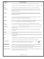
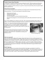
UL label location
CABP3
UL marking is on the serial number label attached to the housing cover next to the access plate.
DMO
UL marking is on the serial number label inside the oven against the left wall. To view, open the oven door.
EHD
UL marking is on the serial number label located in the rear panel. To view, remove the filters.
ERD30S06
UL marking is in the Rating Label located in the left side of the kick panel. To view, open the door.
UL label is also in the serial number located inside the unit in the right hand side wall. To view, look
through the intake grill slots.
ERSD30
UL marking is in the Rating Label located in the left side of the kick panel. To view, open the door.
UL label is also in the serial number located inside the unit in the right hand side wall. To view, look
through the intake grill slots.
POLICIES
AND
PROCEDURES
ERSD36
UL marking is in the Rating Label and serial number label located in the wall behind the door latch. To
view, open the oven door and look through the intake grill slots.
ERSD48
UL marking is in the Rating Label and serial number label located in the wall behind the door latch of the
36” oven. To view, open the 36” oven door and look through the intake grill slots.
ESG
UL marking is in the Rating Label located in the back of the unit right behind the left rear burner.
ETT/CER
UL marking is on the serial number label located on the bottom of the unit next to the electrical connection.
MODULES.
UL marking (if any), is on the serial number label located in the opposite side of the electrical connection
(beneath the handle).
PGR
UL marking is on the front of the front case top. To view, open the oven door and look through the
intake grill slots.
REMP3
UL marking is on the serial number label attached to the main housing wrap behind the protective rack
left of the access plate.
RSD
UL marking is in the Rating Label and serial number label located inside the storage compartment at the
left hand side wall.
RSE
UL marking is on the serial number label located inside the storage compartment at the left hand side wall.
RV
UL marking is on the serial number label located in the front plenum above the access panel.
SGM/SGMEM
UL marking is in the Rating Label underneath of unit next to gas connection.
marking is also on the serial number label located next to the rating label.
WALL OVENS.
DOUBLE OVENS
SINGLE OVENS
WARMING OVENS
For SGM’s only the UL
UL marking is on the serial number label located inside the intake grill, at the left hand side of the door
latch. To view, open the upper door and look through the slots of the intake grill.
UL marking is on the serial number label located inside the intake grill, at the left hand side of the door
latch. To view, open the door and look through the slots of the intake grill.
UL marking is on the serial number label located at the bottom of the cabinet at the left hand side. To view,
the drawer must be pulled completely open or removed.
Technical Manual - Page 2
ERC Failure Codes
-F0- Shorted Or Jammed Input Device
This failure will appear if a shorted or jammed input device is defective. Possible causes include
shorted wires or a defective membrane switch.
-F1- Alarm “System Watchdog Circuit”
The system will detect a failure in the internal watchdog element relay circuits and will activate a
cancel feature. F1 will be displayed in the time digits and will beep until the cancel button or another
function is selected. An F1 failure could be detected in cook or time of day mode. With an F1 failure
the ERC is picking up a command to supply heat without receiving an input from the membrane. The
watch dog circuit is designed to prevent this.
If the beep continues after pressing cancel check the main control (ERC)
-F2- Alarm Heating Mode High Temperature
Is activated when the ERC senses a runaway heat condition or when the temperature exceeds
“runaway limits”. The ERC will beep until the cancel or another function is selected. If the alarm
repeats the F2 alarm check the oven sensor and wiring after first checking for a stuck relay. If alarm
goes away verify the oven will complete a clean cycle without any type of failure.
-F3- Alarm Shorted Oven Sensor
Occurs when the ERC senses a short circuit in the oven temperature sensor for 16 temperature conver
sions in a row. F-3 will appear in the digits and a beeping will be heard. If the alarm does not go away
after pressing the cancel key check the sensor and wiring.
**Important Note:
This test will only be performed while a cooking operation is being attempted. The F3 alarm will not
be displayed in the time of day mode.
-F4- Alarm Open Oven Sensor
“F4” will be displayed along with a beeping if the ERC determines an open oven temperature sensor
circuit for 16 consecutive oven temperature conversions.
**Important note: This test will only be performed while a cooking operation is being attempted.
The F4 mesage will not be displayed in the time of day mode.
**Important note: If the oven sensor is open the bake modes cannot be activated. The controls
will be non-responsive. Look for this failure, as at first appearance you may suspect the ERC or
selector instead of an open sensor. A strange number may also appear in this failure mode.
Technical Manual - Page 3
Failure Codes
(Continued)
-F5- This Code Is Not Used
-F6- Alarm EEPROM Checksum Error
The brain of this oven (so to speak) operates a series of software commands. These commands control
the various features and functions of the oven. A numerical value has been assigned to each function or
operation. The numerical values can be added up - this is the check sum operation. Every time the
system is powered up and after each clean cycle the system performs a check sum and compares
the value to the value programmed into the software. (stored in memory.)
An EEPROM check sum error or F-6 alarm occurs when the values differ. Only the time of day and
timer operation will operate. If you receive a F-6 alarm replace the ERC.
-F7- Alarm Door Lock Enabled Above Temperature
“F7” wil appear in the digits and a beeping will be heard if a failure in the clean lock/ phase circuitry is
detected for 16 seconds in a row. Check the door lock switches and door adjustments.
-F8- Alarm Door Locking Switch
Occurs when operating the door lock motor if the motor runs for two minutes without seeing the phase
switch change positions. This failure will normally occur only when a clean mode is started. If it
occurs check the door switches and wiring.
Technical Manual - Page 4
Dacor Model Number Designations
CPS
CPD
PCS/D
MCS/D
ECS/D
DMO
ECPS
ECPD
CPTS
CPTD
RSG
RSD
RSE
ERSD
ERSD
RV
REMP3
CABP3
SGM
SGMEM
SGG
ESG
ECC
Modules:
EM1
EM3
EM4
EM5
CER
Convection Plus – single oven, convection
127 – Single oven 27 inch
227 – Double 27 inch, top only convection
Double convection ovens
Microwave Oven
Epicure Series, single oven, convection
127 – Single oven 27 inch
227 – Double 27 inch, top only convection
Epicure Series, Double Convection ovens
Touch Top, Single Convection
Touch Top, Double Convection
Range – All Gas
Range – Dual Fuel (Electric Oven)
Range – All Electric
Range, 30” -- Epicure Dual Fuel (Electric Oven) 15,000 BTU’s
Range, 36&48” Epicure Dual Fuel Range Gas IR Broiler
Raised vent
Remote Blower
Cabinet Blower
Cooktop –Sealed Burner Gas Metal Top 30,36,46 inches
Cooktop – Sealed Gas Metal plus Electric Module 36,46 inches
Cooktop – Sealed Gas Glass Top
6 Burner Cooktop, 15,000 BTU’s
36, 48 inches
Electric Convertible Cooktop
POLICIES
AND
PROCEDURES
EWO
MWO
PWO
2 coil elements
Wok/Canning
Ceramic Glass
Barbecue
Electric Ceramic Cooktop
(ceramic electric radiant)
Electric Touchtop Cooktop
(electric touch top)
Epicure Warming Oven
Millennia Warming Oven
Preference Warming Ovens
Accessories:
AE13
AG13
A20A
A30
ASP10
AG14
AG11
AWR
Griddle for Electric Module
Griddle for Gas Grate
Rotisserie
Wok
Simmer Plate
Griddle for Epicure Cooktops/Ranges
Griddle for 30” cooktop
Wok Ring
ETT
Technical Manual - Page 5
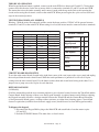
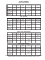
SERIAL NUMBER FORMAT
2 LETTERS FOLLOWED BY 7 NUMBERS
ex: CA6520001 is an electric cooktop made in the last week of 1996
FIRST LETTER
A
B
C
D
E
F
H
M
R
S
T
V
W
Accessories
Blowers
Electric Cooktops
Displays
Electric Modules
Ranges
Hoods
Metal Cooktops/Gas & Dual Fuel
Raised Vents
Surface Vents
Electric Cooktops – Ceran
Wall Ovens
Warmers
POLICIES
AND
PROCEDURES
SECOND LETTER
Identifies the revision level of the model. New models start with an A and as product enhancements are made the
revision level will change. Letters I and O will not be used.
FIRST NUMBER
Last digit of year in which the product was manufactured
1 – 2001
2 – 2002
3 – 2003
4 – 1994
5 – 1995
6 – 1996
7 - 1997
8 – 1998
9 – 1999
0 – 2000
2nd and 3rd NUMBERS
01 THROUGH 52 indicates the week of the year that the product was produced
01 – week 1
02 – week 2
03 – week 3
etc.
The last four numbers are the actual serial number of the product.
Technical Manual - Page 6
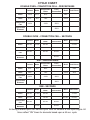
Serial Number Format
In 2002 Dacor changed the serial number format slightly to accommodate additional product line growth by adding two (2)
characters each for product code and revision and two (2) digits for the year of manufacture.
Prior to the 38th week of 2002 the serial number format was:
�
�
�
����
��
������������
���������������������
��������
�������������������
�������������������
A dash was added to separate the two codes - so that a serial number ABC representing product type AB at revision C
could not be confused as a product type A at revision BC. There is also a dash added between the revision code and year of
manufacture. The year code was increased so a unit manufactured in 1992 would not be confused for a unit manufactured
in 2002.
The new serial number format will read:
��
��
��
��
������������
����
���������������������
��������
�������������������
�������������������
The new serial number format for a PGR30 manufactured at revision F on 9/18/02 with the unique number
of 1234 would read: K – F – 02381234.
The new format is being implemented on all product manufactured as of week number 38 of 2002.
TO THE AUTHORIZED SERVICE COMPANY
Our mission is to ensure that Dacor customers receive prompt, courteous and professional service. We are here to
provide support to the servicer with technical information and replacement parts.
SCOPE
The customer warranty program provides home service on Dacor products, at no charge to the consumer.
The warranty begins from the date of original purchase or the date of installation. The warranties on
individual products vary, please see the actual warranty that accompanies each product. Some products carry
an extended parts warranty.
Warranty service must be performed by an authorized service agency in accordance with a written service
agreement provided by Dacor. See warranty matrix for a warranty description by product.
POLICIES
AND
PROCEDURES
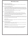
WHAT IS INCLUDED IN THE CUSTOMER WARRANTY PROGRAM
1. Travel time to consumer’s residence.
2. Diagnosis of the problem and completion of the repairs.
3. Replacement of warranty parts.
4. Distributor/Dealer stock merchandise. This includes repairs to correct any defect in materiel or workmanship. A SPECIAL AUTHORIZATION must be obtained in advance for all Distributor or Dealer stock
repairs (see section on Service Authorizations, page 4).
5. All repairs must be made in accordance with Dacor’s recommended procedures and industry accepted
repair techniques along with any governmental rules or guidelines. Only Genuine Dacor Replacement
Parts shall be used.
6. Repairs to correct defects in materials and/or workmanship as outlined in the product warranty.
WHAT IS NOT COVERED IN THE CUSTOMER WARRANTY PROGRAM
1. Repairs made on any unit in which the model and/or serial number have been altered, defaced or removed.
2. Routine maintenance as outlined in the Use and Care booklet. Such maintenance is the owner’s responsibility.
3. Delivery, installation or reinstallation of any product unless an Authorization Number is obtained prior to
doing the work (see section on Service Authorizations).
4. Replacement of cooktop grates, burner caps, filters, knobs, grills or any other part removable for routine
maintenance.
5. Repairs associated with normal use and wear are not considered to be defects in materials and workmanship.
6. Repairs to correct errors in installation or misuse by the consumer.
7. Customer education.
8. Damage to the product caused by shipping or other means.
Technical Manual - Page 7
POLICIES AND PROCEDURES
LABOR RATE STRUCTURE
A warranty claim shall be defined as charges allowed, based upon a previously approved labor rate, accepted by
Dacor and the authorized service agency to make necessary repairs as specified under the terms of the product
warranty. The negotiated rate is defined on the Contractors Rate Schedule. All deviations from this rate require
a Special Authorization (see Special Authorizations page7)
It is the policy of Dacor to negotiate service labor rates on an individual basis. Our intention is to be reasonable
and comparable for the market being serviced. The service labor rate, agreed to by the servicer, is factored to
include travel time, diagnostic and repair time.
TECHNICAL SUPPORT
Dacor has full time technical advisors available to help with diagnostics and problem solving. When contacting an
advisor you must have your authorized service agency number, the model and serial number of the product, and the
purchase date. Our technical advisors can be reached at (800) 353-2267, Monday through Friday between the hours of
5:00 AM and 4:00 PM Pacific Standard Time.
POLICIES
AND
PROCEDURES
CUSTOMER SUPPORT
The Customer Service Department provides support to Customers, Dealers, Product Distributors, Service Agencies and
Parts Distributors. They are responsible for resolving customer complaints. When evaluating a complaint they consider
the following:
AGE OF THE PRODUCT
SERVICE HISTORY
NATURE OF PROBLEM
COST AND EXTENT OF THE REMEDY
Periodically we may contact you for copies of repair invoices to help evaluate a customer inquiry. Our Customer Service
Department can be reached at (800) 793-0093 Monday through Friday between the hours of 7:00 AM and 4:00 PM
Pacific Standard Time.
ADVERTISING PROGRAMS
Dacor does not offer an advertising or co-op program.
SERVICE LITERATURE
Upon acceptance as an authorized service agency or parts distributor, Dacor will provide one free set of service and
parts manuals. Periodic updates will be provided at no charge. Additional sets are available for purchase. Service
literature must be ordered directly from Dacor. It is the service agencies responsibility to keep current literature on
Dacor products. Dacor will supply service updates (field service bulletins) on a regular basis, at no charge, only to
authorized service agencies.
INSTRUCTIONS FOR SUBMITTING WARRANTY LABOR CLAIMS
Dacor warranty claims are processed and entered “online” at www.dacorservice.com. To begin processing your warranty
claims online, contact warranty administration or your regional technical manager to get your login and password.
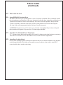
CONSUMER AUDIT PROGRAM
All claims are subject to an audit by direct contact with the consumer, a field service, sales representative or by other
means. Any claim for service and/or parts the consumer denies receiving or conflicting consumer technicians statement
of service performed will be charged back to the servicer. All complaints of fraud will be turned over to the appropriate
Technical Manual - Page 8
governmental agency. Submitting fraudulent claims is grounds for immediate termination of the service agreement.
The consumer audit program will also include a customer satisfaction survey. Consumer complaints, comments,
suggestions will be forwarded to the service agency.
PROOF OF PURCHASE
Proof of Purchase to verify the status of any warranties shall include original bill of sale, closing papers of the new
dwelling, cancelled check or occupancy papers in the case of a remodel. The model and serial numbers are required
on the NARDA form along with the purchase date. The accuracy of this information is the responsibility of the
service agency.
SPECIAL AUTHORIZATIONS
All Non Warranty, Dealer/Distributor stock, or extensive warranty repairs being charged to Dacor must have prior
approval from a Dacor Customer Service Representative and a written Service Authorization. The Service Authorization
number must be written on the NARDA invoice and submitted for payment in the same manner as a warranty claim.
See exhibit C for a copy of the Service Authorization form being used. Claims submitted without this number may
be delayed or declined.
POLICIES
AND
PROCEDURES
RETURN AUTHORIZATIONS
For the return of a product or replacement part, Dacor requires and issues Return Authorizations (RA’s) A completed
authorization specifically describes the cost, product, or part being authorized for return. The return authorization
number must be written or clearly identified on the shipping container or the package may be refused. No credits or
payments other than specified on the authorization will be made unless Dacor amends that authorization.
Return Authorization for finished product is only considered when all service remedies are exhausted. Returned product
may be examined to determine or verify the previous service work performed on the product. The service agency will
be contacted about any errors or discrepancies.
PARTS DISTRIBUTION
Dacor sells parts to a network of independent parts distributors, who sell replacement parts to our network of
independent service agencies. Authorized service agencies receive a 25% discount from the published retail price.
Parts Distributors provide warranty parts and issue credits for warranty repairs directly to the service agency. It is the
responsibility of the service agency to establish an account or a business relationship with their local parts distributor.
Parts distributors are provided with a recommended stocking list. In addition, each parts distributors inventory is
reviewed quarterly. Parts ordered in error or other parts requested for return may be subjected to a restocking fee. Dacor
is committed to supporting its parts and service network and understands the importance of having replacement parts
readily available. Dacor reviews all part return requests individually and will not penalize a distributor who attempts
to maintain complete parts inventory.
PARTS SHIPPING POLICY
Replacement parts are shipped to parts distributors from Dacor, freight prepaid with the exception of air shipments
(please see the authorized Parts Distributor Agreement for specific details). The parts distributor is responsible for
freight costs on all warranty parts. Large parts such as oven cells should be drop shipped directly to the service agency.
EMERGENCY PART ORDERS
An order identified as an emergency and received prior to 12:00 PM (Pacific Standard Time) will ship that day. If an
air shipment is requested the parts distributor will be billed for air freight. An emergency order received after 12:00
PM will be shipped the following day.
DROP SHIPMENT OF PARTS
If requested by a parts distributor, replacement parts can be drop shipped directly to the service agency. This practice
is recommended for large parts, such as oven cells.
Technical Manual - Page 9
PARTS RETURN POLICY
Effective March 1, 2000 Dacor implemented a Factory Direct Parts Return Policy. Each part to be returned should
be shipped back in the original container with the shipping label enclosed in the replacement box. A copy of the
NARDA/USA claim form should be enclosed with the part being returned. This new policy will not affect Canada.
WARRANTY REPLACEMENT OF GAS COOKTOP GRATES AND CAPS
In recent years, manufacturers have developed new lighter colored gas cooktop grates and burner caps. Lighter
components show signs of normal wear more quickly than the traditional black components. Warranty will cover
defects in materials or workmanship but not normal wear. Due to the high cost of these parts, Dacor does not authorize
parts Distributors or service agencies to replace these parts under warranty. If you have a customer requesting gas
cooktop grates or caps (under warranty) please refer them to our customer service department.
Credit will not be issued on replacement caps and grates submitted as warranty without prior authorization.
PROCEDURE FOR SUBMITTING PARTS WARRANTY CLAIMS
Please see previous section “processing a labor claim” explaining the distribution of the NARDA claim form. The Parts
Distributor would send the PINK copy of the NARDA to Dacor along with any summary or debit form preferred.
POLICIES
AND
PROCEDURES
REPLACEMENT PART WARRANTY
Replacement parts are guaranteed for one year from the date of installation. A copy of the original service invoice must
be included with the part when returning to the parts distributor for credit.
Technical Manual - Page 10
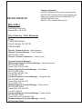
DACOR CONTACTS
Telephone Numbers
626-799-1000 Main Office and Customer Service
800-353-2267 Technical Service (technicians only)
Sales and Customer Service Fax 800-866-7147
626-934-9065 Parts Fax
909-612-1702 Technical Service Fax
Main Office
Dacor
1440 Bridge Gate Drive
Diamond Bar, CA 91765
City of Industry - Parts Shipments
Dacor
14425 Clark Street
City of Industry, CA 91745
626-961-6406
Director, Technical Service – Kevin Leedom
National Technical Manager - Thom Tompkins
800-793-0093 X3602
Director, Customer Satisfaction – Cheryl Crowe
Regional Technical Managers
West Central Regional Technical Manager - Darrell Kummerle
800-793-0093 X4606
Home Office 916-789-1094
Eastern Regional Technical Manager – Kurt Moses
800-793-0093 X3604
Home Office 860-482-1340
Fax 860-482-1342
Southern Regional Technical Manager – George Brands
800-793-0093 X3603
Home Office 678-334-3130
Fax 678-344-3126
Midwest Regional Technical Manager – Randy Renfro
800-793-0093 X4603
Home Office 972-412-8976
Fax 972-412-4315
Southwest Regional Technical Manager – Adrian Acosta
800-793-0093 X4675
Home Office and Fax 909-484-7906
Northwest Regional Technical Manager - Ron Hill
800-793-0093 X4602
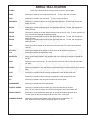
SERIAL TAG LOCATION
CABP3
DMO
Serial Tag is attached to the housing cover next to the access plate.
Serial tag is inside the oven against the left wall. To view, open the oven door.
UL LABEL
AND
SERIAL TAG
LOCATION
EHD
Serial tag is located in the rear panel. To view, remove the filters.
ERD30S06
Serial tag is located inside the unit in the right hand side wall. To view, look through the
intake grill slots.
ERD36
Serial tag is located inside the unit on the right hand side wall. To view, look through the
intake grill slots.
ERD48
Serial tag is located on the wall behind the door latch of the 36” oven. To view, open the 36”
oven door and look through the intake grill slots.
Serial tag is located inside the unit on the right hand side wall. To view, look through the
intake grill slots.
Serial tag is located inside the unit on the right hand side wall. To view, look through the
intake grill slots.
ERG30
ERG36
ESG
Serial tag is either located on the side wall or the back wall. The unit must be pulled to
view tag.
ETT/CER
ILB
Serial tag is located on the bottom of the unit next to the electrical connection.
Serial tag is fixed to the flat surface wrap.
MODULES
Serial number label located in the opposite side of the electrical connection (beneath the
handle).
PGR
Serial tag is the front case top. To view, open the oven door and look through the intake
grill slots.
REMP3
Serial tag is attached to the main housing wrap behind the protective rack left of the access
plate.
RSD
Serial tag is located inside the storage compartment at the left hand side wall.
RSE
Serial tag is located inside the storage compartment at the left hand side wall.
RV
Serial tag is located in the front plenum above the access panel.
SGM/SGMEM
Serial tag is located next to the rating label.
DOUBLE OVENS
Serial tag is located inside the intake grill, at the left hand side of the door
latch. To view, open the upper door and look through the slots of the intake grill.
SINGLE OVENS
Serial tag is located inside the intake grill, at the left hand side of the door latch.
To view, open the door and look through the slots of the intake grill.
WARMING OVENS
Serial tag is located at the bottom of the cabinet at the left hand side. To
view, the drawer must be pulled completely open or removed.
Technical Manual - Page 12
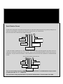
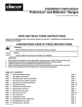
Electrode Detection of a Gas Flame
Theory of Operation
If you look closely at a finger of burner flame you will see that it is
clearly made up of three separate elements:
(see figure 1)
1. Inner fuel rich cone
2. *Ionized blue outer cone with current carrying capabilities
3. Outer air rich mantle.
When gas combined with air; burned energy is released in the form
of heat and light. When the gas / air mixture is controlled, the outer
blue cone will actually carry electrical current similar to a wire.
2
3
1
Figure 1
If we place a metal probe into this “Ionized Plume” and apply a voltage between it and the burner,
current will flow. An important characteristic of a burner/flame/electrode assembly is its ability to
mainly pass current in one direction. It behaves as a one way valve or rectifier.
Flame Rectification systems make use of this directional characteristic when detecting a good
flame to distinguish it from leakage currents that can arise due to moisture contamination, soiled
igniter tip, poorly grounded burner spreader ring / burner head, cracked igniter insulation or poor
house ground.
A voltage of alternating polarity (an AC voltage) is applied to the electrode from the spark module
and the resultant current flow which is greater in one direction than the other, is electronically
detected. This current is very small, about one microamp (one millionth of an amp).
The Dacor re-igniter has a specified minimum flame current that will be sensed as a flame of
0.5 microamps (1.3uA minimum sensitivity for C664 Series Gas Ignition Systems). The minimum
recommended flame current measured under all likely conditions in an installation should be 1.0
microamps for re-igniters (2.0 microamps for C664 Series). When a burner flame is present the
Ionized outer cone will be producing a small DC current. This current is known as (Flame Current).
The flame current has to be at a certain level to allow voltage from the spark module to flow
efficiently.
The accurate placing of the electrode in the flame is important.
This igniter tip needs to be perfectly located in the ionized outer
blue cone to effectively send and then detect current flow.
To break it down further, the spark module
acts as a simple capacitor. It saves voltage like a sponge
until it can hold no more. It will save and release this voltage
approximately 3 times per second. When the voltage is released it follows the spark wire until
reaches the spark electrode tip. The built up voltage wants to leave the tip and move to the
point of least resistance. In a healthy situation this will be the burner spreader ring. From the
burner spreader ring the voltage flow will pass through the burner head, burner tube, chassis and to
ground. An interruption of this current path will cause the spark system to misbehave.
Technical Manual - Page 13
The flame also plays a very important role in this process. Because the flame is conductive, it
allows the voltage to pass through its body like a bridge to the burner spreader ring. This {bridge}
allows the built up spark voltage to bleed off of the igniter tip and move to ground more easily. The
resultant ionized flame bridge has now become the path of least resistance for the spark to take
across the gap between the spark electrode and the burner body.
By bleeding off the buildup of voltage we stop the spark from occurring. The spark is, in effect,
still there, you just canʼt see it.
* Ionized / To separate into Ions or to become electrically charged.
In order to successfully detect a flame we first need to;
1.
2.
3.
4.
Place the electrode in the correct position under all flame conditions.
Ensure the flame is stable and does not “lift off” the burner at the ports adjacent to the
electrode and put the flame beyond the electrode. It is very important to have a stable flame
especially around the igniter tip.
Ensure there is a secure ground path to earth from the burner spreader ring / burner head.
Confirm the appliance is properly connected to earth ground.
Current Path
The current path for detection is through the spark electrode, outer plume of flame, burner spreader
ring, burner head, burner base, chassis and earth ground. If this path is broken, the current cannot
flow and sparking will occur. A proper flame will keep this from happening. In other words, the
current will always flow through the path of least resistance and it might not be on top of the
cooktop, it might be below the top frame and out of sight. In this case, suspect a defective spark
wire or a pinched spark wire.
Do you have a ground prior to the igniter tip?
If there is a current path (leak / ground) prior to spark electrode,there will likely not be a spark
pulse between the electrode and the burner spreader ring. This phenomenon is what leads most
servicers to believe they have a defective spark module.
The spark module can tolerate a relatively large leakage before going into fault condition and
generating a spark. The tolerance to leakage decreases with an increasing amount of flame current
therefore it is desirable to obtain a high flame current at the appliance design stage to provide
some allowance for increasing leakage with age and use. The better the flame current / ground,
the less likely there is to be reignition.
Possible Causes Of Continuous Sparking:
Defective spark wires.
Continuous high heat can cause spark wires to degrade. Use volt/ohm meter to determine continuity of spark wires. Look for obvious cuts/ abrasions or pinch points. A defective wire can allow
spark voltage to transfer through insulation to ground prior to reaching spark electrode. Under
normal circumstances all igniters fire together and if the burner in question has found an easier
ground path the spark will go there. It will not, however, in most cases have found a CONTINUOUS
ground path such as what the flame would provide under normal circumstances. This will cause
the spark module to re-ignite.
Technical Manual - Page 14
Cracked Ceramic Spark Electrode
Itʼs important to determine whether the spark electrode is faulty. Physical impacts and high heat
can cause the ceramic post to fracture or crack. If this occurs the spark can shoot through the
ceramic insulation and will normally go to ground on the burner head rather than through the flame
/burner spreader ring.
Faulty Burner Grounding
From the spark electrode / burner spreader ring to earth ground it is important that you have a
strong connection. This can be interrupted in many different ways.
Soiled spark electrode
Soiled burner spreader ring
Soiled burner head
Corrosion between the burner head and burner tube.
Normally this will appear as a brownish stain and can be easily cleaned with a small wire
brush.
Any of these conditions can interrupt current flow. We recommend frequent cleaning with a stiff
plastic or soft wire bristle brush using pure alcohol or a window cleaning solution that contains
alcohol. It is commonly thought that simple igniter cleaning
is enough, it is not. You have to clean all three conductive
components to ensure good continuity. A small amount of
grease or oil can act as an insulator and prevent the spark from
flowing properly.
The burner head and burner tube connection has to be tight.
The fastening ring that holds them together has to be seated
properly in order for the two components to properly pass
electrical current.
Burner Fastening Ring
Poor house ground
If you have thoroughly diagnosed the spark system and continue to have erratic sparking do not
dismiss the home ground as the culprit. Many older homes that are being remodeled do not have
adequate ground systems in place to handle todayʼs demands. A quick diagnostic tool is a 20-foot
piece of 16-gauge wire with alligator clips on each end. This can be used a temporary {jumper}
to a known ground source. If the problem is eliminated when you connect the {jumper} you have
to suspect the home ground as the culprit. When tested, the Neutral and ground should share
less than 20 volts.
Erratic Sparking
It is common to find one or a series of burners that will only spark occasionally. As with the
previously described scenarios check all possible ground faults. This is the number one cause of
erratic sparking, not spark modules as is more commonly thought. If you have made certain that
you have a strong flame current / flame placement / solid ground; replace spark module.
Technical Manual - Page 15
Excessive Failures:
Diagnosis on a spark system can be confusing. For some, diagnosing spark failure is difficult while
for others it is pure luck to get it right. Often you can eliminate a problem by disassembling the
cooktop and putting it back together. In the process most technicians will have installed a new
spark module and assumed thatʼs what repaired the unit. What they have likely done is improved
a ground path in the reassemble process. Most gravitate to what they have heard {just change the
spark module} Dacor monitors the return of spark modules and NARDA claim forms. The statistical
data clearly shows that a vast majority of modules being replaced are not faulty since over 83% of
the spark modules returned to Dacor for credit are tested as “good” product.
The following “fault descriptions” have been taken directly from the NARDA claims submitted:
Burner no light
Rear burner making a “popping noise”
When one burner is turned on others click
Sparking continues long after flame
Constant sparking
Burner intermittent sparking
Clicks but will not light
Takes too long to light
None of these reasons for service are accurate indicators of a faulty igniter module.
As with any Flame Rectification Reignition system, the Dacor flame reignition system does have
some critical issues that may prevent its correct function.
These are:
Partially open valve
90% of the trials will not light the flame but will cause spark.
Downdraft Ventilation
Might affect the re-ignition of the small H-Burner in the simmer setting
Clogged Valve
Not an adequate volume of gas. It will take longer to light the burner.
Poor Grounding
Might damage the module.
Reversed Polarity
Will cause constant sparking when unit is turned on.
Faulty spark leads
A broken wire may allow for a spark but not for flame sensing.
Leakage path to ground
Condensation or moisture on the electrode or dirt build up will cause poor grounding.
One of more burners will not stop sparking unless a certain sequence of burners are turned on
at the same time.
This indicates mismatched spark wires. Each individual burner wire has to go to a specific burner.
The spark switch located on each gas valve is connected to the spark module input side. This
connection determines which burner the module {listens} to. If the wiring sequence is incorrect the
module does not know what to look for.
Consistent But Weak Spark
After giving close inspection to the spark wires, spark electrode, burner head /burner base and
Technical Manual - Page 16
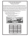
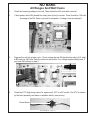
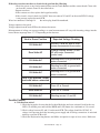
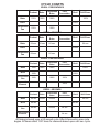
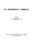
OUTPUT VOLTAGE CHECK POINTS
ON ERC/CLOCK CONTROL
All Ranges And Wall Ovens
When programming the oven into a cooking cycle, you first select the desired mode on the
touch membrane. Pressing this key sends a message to the ERC/Clock control, which in
turn triggers 24 Volts DC to be sent to the main relay board through the connective harness.
The desired relay (for example, Pure Convection) closes and distributes power to the desired
components. In order to correctly diagnose this sequence you need a volt meter set on DC
voltage. Drop the Bezel/Control panel down thus exposing the ERC/Clock and related wiring.
Dropping the control panel down will expose the back side of the ERC/Clock control and
main wiring harness. The connective harness will have 16 pins. Using a voltmeter take the
test leads and insert into the backside of the main wiring harness
To take a voltage reading using the ERC connection chart below:
1. Set the voltage meter to DC voltage
2. Insert the test lead into the backside of the main harness
(plugged into the backside of the ERC control.)
For example: if bake isn’t working:
a) Insert the test leads into connections (2-5)
b) Program the unit into the bake cycle
The meter should read 22-24 Volts AC
TEST POINT 1
TEST POINT 16
ERC CONNECTOR
B etw een P ins
R elay
S hould R ead
1-3
D BL
24 V OLTS
2-5
BAKE
24 V OLTS
2-6
B ROIL
24 V OLTS
2-7
C ONV E C TION
E LE ME NT
24 V OLTS
2-9
C ONV E C TION
FA N
24 V OLTS
1-11
D OOR MOTOR
(LATC H MOTOR)
24 V OLTS
1-13
C OOLING FA N
24 V OLTS
Technical Manual - Page 17
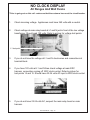
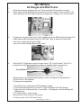
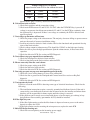
NO CLOCK DISPLAY
All Ranges And Wall Ovens
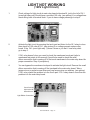
**Prior to going out on this call - make sure that the customer has re-set the circuit breaker.
1.
Check incoming voltage. Appliances must have 240 volts with a neutral.
2.
Check voltage at main relay board at L1 and N just in front of the low voltage
transformer. Should read 120 volts. Refer to picture for voltage test points.
L1 test point
3.
If you do not have the voltage at L1 and N check wires and connections at
terminal block.
4.
If you have 120 volts at L1 and N then check voltage at main ERC
harness connection coming off ERC clock control. Refer to picture for
test points 14 and 15. Should have 22-24 volts AC input to ERC/clock control.
1
5.
If you do not have 22-24 volts AC, suspect the main relay board or main
harness.
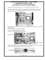
Technical Manual - Page 18
NO BAKE
All Ranges And Wall Ovens
1.
Check the incoming voltage to the unit. There should be 240 volts with a neutral.
2.
Check power at the Dbl (double line relay) from (Com) to neutral. There should be 120 volts
incoming to the Dbl. Refer to picture for testpoints. If voltage is ok, movetostep3.
3.
Program the unit into a bake cycle. Check voltage across Dbl (double line relay) (N.O. side)
to BA relay for 240 volts. Refer to picture for test points. If no voltage replace relay board. If
you have 240 volts go to step 4.
4.
Check the HTC (high temp cutout) for open circuit. HTC is a NC switch. The HTC is located
by the latch assembly and has a re-settable switch. (see picture)
Reset Button
Technical Manual - Page 19
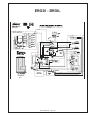
NO BROIL
All Ranges And Wall Ovens
1.
2.
Check the incoming voltage to the unit. There should be 240 volts with a neutral.
Check power at the Dbl (double line relay) from (Com) to neutral. There should be 120
volts incoming to the Dbl. Refer to picture for testpoints. If voltage is ok, move to step 3.
3.
Program the unit into a broil cycle. Check voltage across the DBL (double line relay) N.O.
output side and BR relay (Broil relay) For 240 Volts. Refer to picture for test points.
If you have voltage present go to step 4.
If you do not have voltage replace relay board.
4.
Check the HTC (high temp cutout) for open circuit. HTC is a NC switch. The HTC is
located next to the latch assembly and has a re-settable switch. (see picture)
Re-set Button
There is also a user programmable option to set the cooling fan off temperature to
200, 300, 400 or 450 degrees.
To change the temperature:
1. Touch Broil pad - enter temp as 500 degrees or higher.
2. Push and hold Broil pad for 5 seconds - COOL will show in the ERC display
3. Adjust fan shut off temp with the +/- pad. (000 = 450 degrees, all other settings will
display temp).
4. To exit the mode - press cancel.
Recommended factory setting is 300 degrees
This will only work on EC, MC and PC ovens
Technical Manual - Page 20
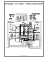
PURE CONVECTION - NO HEAT
(MCS/MCD, ECS/ECD, ERD,
RSD, RSE, CPS, CPTS, ECPS ERSD)
1.
Check the incoming voltage to the unit. There should be 240 volts with a neutral.
2.
Program the unit into pure convection. Check power at the Dbl (double line relay) from
(Com) to neutral. There should be 120 volts incoming to the Dbl. Refer to picture for
test points. If voltage is ok, move to step 3.
3.
Check voltage across the Dbl (double line relay) NO output side and the CVL (convection
element relay)
for 240 volts. Refer to picture for test points. )
If you have voltage present move to step 4
If you do not have voltage replace relay board.
Double line relay
Convection Element
Relay
4.
Check the HTC (high temp cutout) for open circuit. HTC is a NC switch. HTC is located by
the latch assembly and has a re-settable switch. (see picture)
Re-set Button
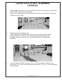
Technical Manual - Page 21
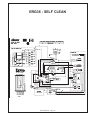
DOOR LATCH NOT RUNNING
(All Models)
1.
Check voltage at L2 just to the left of the DRLK relay. (door lock relay) you should have
120V present. See picture for test points.
If there is no voltage present, check wiring from L2 back to terminal block. If you have
voltage at L2 go to step 3
2.
3.
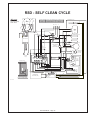
Program oven into self-clean cycle.
Check voltage from the DRLK (door lock relay) to neutral. See picture for test
points. Should have 120 Volts. If no voltage is present replace relay board.
If voltage is present check wiring to door latch assembly. If ok replace door
latch assy.
4.
If you do not have 120VAC, check for (+ or -) 24V DC at molex connector on the
relay board. Pins 1 and 9 on relay board should read 24V DC (+or-); if not then replace
the relay board.
Technical Manual - Page 22
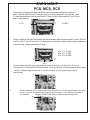
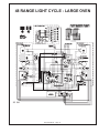
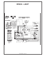
OVEN LIGHT
PCS, MCS, ECS
1.
Check input voltage to the light transformer at the primary side across terminal 1
and 5. Should read 240 volts. (see picture) If you do not have 240 volts across 1 and
5, check wiring back to the terminal block. If there is 240 volts present at 1 and 5 go to
step 2. (see picture)
1= 0V
1
5
5=240V
Step 1
2.
Check voltage at the light transformer on the secondary side across terminal 6 and 8. Should
read 12 volts. If you do not have 12 volts present at terminal 6 and 8 replace light transformer.
If you do have voltage present go to step 3.
6 to 8 = 12 VAC
8 to 10 = 12 VAC
6 to 10 = 24 VAC
6
10
8
Step 2
3.
Check voltage from the main relay board at terminal N which is to the left of OL1 relay.
Should have 12 volts present at N all the time. If you do not have 12volts present re-check steps
1 and 2 or replace light transformer. If you do not have 12 volts present go to step 4.
(see picture)
N
Step 3
4.
Check voltage at OL1 on main relay board. Should have 12 volts present after OL1 relay
closes. If you do not have voltage present recheck steps 1-3 or replace relay board. If
you do have
voltage present Check wiring to light socket and light bulb.
OL1
Technical Manual - Page 23
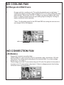
NO COOLING FAN
All Ranges And Wall Ovens
1.
Program unit into a cooking cycle. The cooling fan should come on right away. **
If cooling fan doesn’t come on, check voltage at CVF or CLF relay (cooling fan relay)
side to neutral. Should read 120 VAC. If voltage is not present replace main relay
board. If voltage is present check for open wires going to cooling fan. If wiring ok,
replace cooling fan motor assembly.
**Note: On all models except for the PGR and RSG the cooling fan turns on at an
oven temp of 180 to 230 degrees
NEUTRAL
CVF or CLF
NO CONVECTION FAN
(All Models)
1.
2.
3.
Program the oven into convection bake.
Check voltage at L2 just to the left of the CV (convection relay), should have 120 volts.
See picture. If no voltage check wiring back to the terminal block. If you have voltage
present at L2. Go to step 3.
Check voltage out of the CV (convection relay) for 120 volts. See picture for test points. If
no power out of CV relay replace relay board. If there is voltgage present check wiring,
convection motor and connections.
L2
Technical Manual - Page 24
CV
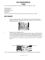
NO BAKE/BROIL
PGR
Here is a list of functional parts that should be working for the bake/broil to light..
Main Relay Board
Cooling blower
Air switch (sail switch)
Dual gas valve
Bake Igniter
All of these elements must be working in order for the bake or broil burner to function.
NO BAKE
1.
Check incoming line voltage to the DBL (double line relay) NO side and neutral.
Should have 120 VAC. If no voltage present trace wiring back to terminal block. If
voltage is present go to step 2.
2.
Program the unit into Bake or Broil.
Check voltage at the DBL (double line relay) com side to neutral. Should read 120
VAC. If no voltage present replace main relay board. If voltage is present then check
if cooling fan is running. If cooling fan is not running check wiring and cooling fan
motor.If cooling fan is running then check the air switch/sail switch that is mounted to
the cooling fan assy. You must remove cooling fan to gain access to air switch/sail
switch.
BR Broil Relay
BA Bake Relay
**Note: The cooling fan should turn on immediately when any cooking cycle is programmed.
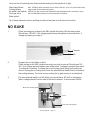
Technical Manual - Page 25
Here is a list of functional parts that should be working for the bake/broil to light
Main Relay Board
Cooling blower
Air switch (sail switch)
Dual gas valve
Bake Igniter
Note: ERG30’s had a sail switch prior to SN KC1230128. On 6-7-01 the sail switch was
replaced with an automatic reset switch.
PGR30’s unit with a serial level KB0000000 and KA0000000 had a sail switch - those
with a KC0000000 and above have an automatic limit switch.
All of these elements must be working in order for the bake or broil burner to function.
NO BAKE
1.
Check incoming line voltage to the DBL (double line relay) NO side and neutral.
Should have 120 VAC. If no voltage present trace wiring back to terminal block. If
voltage is present go to step 2.
Common
NO
2.
Program the unit into Bake or Broil.
Check voltage at the DBL (double line relay) com side to neutral. Should read 120
VAC. If no voltage present replace main relay board. If voltage is present then check
if cooling fan is running. If cooling fan is not running check wiring and cooling fan
motor.If cooling fan is running then check the air switch/sail switch that is mounted to
the cooling fan assy. You must remove cooling fan to gain access to air switch/sail
3.
The air switch/sail switch is a NO switch you should have 120 VAC to that switch.
Take a voltage check from one side of the wire to neutral - it should read 120VAC.
Brown wire to bake igniter
120 Volts
Brown wire to broil igniter
Technical Manual - Page 26
LIGHT NOT WORKING
(120V Light Circuit)
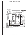
1.
Check voltage for light circuit at main relay board at terminal N, just to the left of OL1
(oven light relay one) Should have a constant 120 volts. (see picture) If no voltage there
check wiring back to terminal block. If you do have voltage present go to step 2.
OL1
N
2.
Activate the light circuit by pressing the touch pad and listen for the OL1 relay to close
then check for 120 volts at OL1. (see picture) if no voltage present replace relay
board. If the OL1 (oven light relay 1) doesn’t close or you don’t hear relay close
go to step 3.
3.
If OL1 relay doesn’t close you need to check the membrane touch pad (refer to
membrane test points in this manual) You will also need to check the small
ribbon connection that is coming off of the touch membrane to the main relay board for
proper connection. Step 4 (see picture)
4.
You can bypass the membrane touchpad to activate the light circuit. Remove the small
ribbon connection that is coming off the touchpad to the main relay board. Take a
jumper wire or a pocket screw driver and jump across pins one and two. (see picture)
If OL1 relay closed the problem is in the touch pad. If OL1 relay doesn’t close then the
problem is in the main relay board.
Count from the
right to the left:
start with one
Light Ribbon Connection
Technical Manual - Page 27
NO BAKE/BROIL HEAT:
ERG30
1.
Check for incoming voltage to the main relay board at the DBL (Double Line Relay) NO
side to neutral. Should have 120 VAC present. If no voltage check wiring back to the
power terminal block.
If voltage is present go to step 2.
2.
After programming the unit into the bake cycle or any cooking cycle “cooling fan must be
running” Check voltage from the com side of the DBL relay to the BA relay (Bake relay)
and the BR (Broil Relay) should have 120 VAC present.
Note: the BA relay and the BR relay are the neutral side to the glow bar igniters. If no
voltage present replace main relay board. If voltage is present go to step 3.
3.
If cooling fan is not running check voltage at L2 next to the CLF relay (cooling fan)
to neutral.
Should read 120 VAC. If no voltage check wiring from L2 back to power terminal
block. If voltage is present check wiring to the cooling fan blower, if wiring ok replace
cooling fan assy.
Technical Manual - Page 28
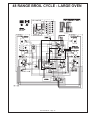
ERD30, 36, 48
Large Oven, No Bake
1.
Check incoming power to range should have 240 VAC with a neutral. Check voltage
going into main relay board from L2 (red) to L1 (black) at main relay board. Should
have 240 VAC.
2.
Program unit into bake cycle, the unit will go into a preheat bake. The bake element
and broiler should activate during pre-heat.
If the bake element doesn’t activate check voltage at the main relay board. At the DBL
(double line relay) NO side to the BA relay (Bake Relay) Check for voltage across
these
two relays. Should read 240 VAC.
If no voltage is present the next check is the HTC (hi temp cutout) which is located
just to the right of the latch assembly.
3.
There are two HTC’s. (High Temp Cutouts) one is for the bake element circuit. The
second one is for the broil cycle circuit. You can tell the difference between them by
the color of the wire going in to the HTC. The Bake HTC has a black wire going in to
the HTC. Line voltage Hot (to bake element) The broil HTC is a white wire.
This is the neutral side to the broil igniter. If the bake HTC is open, push down on
the re-set button located in the center of the HTC. If the re-set button will not depress,
replace HTC. If the HTC is good, check for an open bake element and wiring to the
element.
Technical Manual - Page 29
NO BROIL
ERD30, 36, 48
1.
Program unit into the broil cycle.
Take an amp reading at the broiler igniter. You should have 3.1 to 3.3 amps. Or take a voltage
reading at the main relay board. At the main relay board take a voltage check from the BR
(broil relay) to neutral should read 120 volts AC. If no voltage out of the BR relay - replace
relay board. If you have voltage out of the relay board check the HTC (High temp cutout) to
see if the HTC has tripped.
(Remember the broil HTC has the white wire hook to it. You can do this by pushing down
on the reset button located in the center of the HTC. If the HTC won’t reset or is open,
replace HTC. If the HTC is good, go to step 2.
2.
Dual Valve: The HTC (Hi temp cutout) feeds the neutral into the dual valve then the
dual valve feeds the neutral to the broil igniter. If the dual valve is bad then the broil igniter
won’t be energized.
Technical Manual - Page 30
ERC Quick Test
The process requires two people. To access the program, one person should stand at the oven,
while the other is located at the circuit breaker. The person at the circuit breaker turns off the
breaker and then the person at the oven depresses and holds the cooktime keypad. The person
at the circuit breaker then turns the breaker back on. The display will show the 4-character
identification code of the ERC. Example (1180)
You have 30 seconds between each test mode.
Note: if unit shows time of day start procedure over again.
Test 1
Push and hold convection bake
Bake element and convection fan activate.
Test 2
Push and hold Standard Bake
Bake element activate.
Test 3
Push and hold Pure Convection
Convection fan and convection element activate.
Test 4
Push and hold broil
Broil element activate. (on gas units - ignitor will activate.)
Test 5
Push and hold convection broil (select models)
Broil element and convection fan activate.
Test 6
Momentary push timer 2
Audible tone will sound.
Test 7
Push and hold stop time
Cooling fan activate.
Test 8
Momentary push clock
All LEDs will light up. Push + or - key pad. LEDs wil display numbers
Example: 1111, 2222, 3333, 4444 etc.
Test 9
Last test door open, push and hold cook time for 10 seconds
Self clean latch motor activate. Door latch will complete one cycle.
The test will end and ERC will display the time of day.
NOTE:
Complete all tests within 30 seconds - otherwise you will see a failure code (F-0: Stuck key pad)
displayed on the ERC.
Technical Manual - Page 31
THEORY OF OPERATION
When keypad up/down button is pushed, contacts on the main PCB close between #12 and #13. Closing these
contacts activates the triac for the sleeve motor which is connected to terminals L3 and N3 on the main PCB.
The motor then raises the intake assembly until contact is made with the up stroke limit switch opening the
circuit and reversing the electronic switch on the main PCB. When pressed again, the cycle reverses itself and
stops in the retracted position.
VENT PCB DIAGNOSIS (ALL MODELS)
Warning – With the motor disconnected, and the vent in the down position, 120VAC will be present between
terminals L2 and N2 on the main PCB. When testing for a load, the motor must be connected to these terminals.
K eypad - C ircuit B oard Molex P lug Wiring Order
Terminal #
Old S tyle
N ew S tyle
N ew S tyle
1
brown
dark green
whi te
2
red
brown w/whi te
purple
3
orange
blue
orange
4
yellow
brown
blue
5
green
gray
bk w/stri pe
6
blue
red
dk green
7
purple
purple
li te green
8
grn w/whi te
pi nk
gray
9
red w/whi te
whi te
pi nk
10
orange w/black
orange
red
11
yellow w/black
black w/whi te
brown
12
green w/black
black
orange w/stri pe
13
blue w/black
black
black
14
purple w/whi te
lt green
yellow
Button Contacts
Up/Dow n
12 13
High Speed
11
Medium Speed 5
10
10
L o w S p eed
12 10
Delay
14
Stop
12 14
Clean
11
5
14
CIRCUIT BOARD DIAGNOSTICS
To test the main control board,(located in the right front corner of the vent) remove the access panel and unplug
the touch pad from the main control board. When the touch pad harness is pulled off it will reveal 14 pins
coming from the main control board. Use the button contact chart and circuit board wiring order chart. Use a
jumper wire to jump across the 14 pins for each function.
KEYPAD DIAGNOSIS
(All Models)
Of all the returned keypads the most common problem is poor electrical contact between the Touch Pad and the
Contact Board. In the majority of these cases the Keypad Assembly is replaced unnecessarily. Before replacing
the Keypad Assembly check for a foreign material between the Touch Pad and the Contact Board. Examples
of foreign material include grease, cooking residue, moisture, or residue from cleaning agents. Circuit board
cleaner or equivalent (available from electronic supply stores) should be used to clean the keypad assembly.
To diagnose the keypad:
1. Disconnect the Keypad Molex plug at the Main PCB and attach leads of an ohm meter to pins
#12 and #13.
2. Push the UP/DOWN button. This must show a closed circuit.
Technical Manual - Page 32
If the above test does not show a closed circuit, perform the following.
- Check for grease or any foreign material between the Touch Buttons and the contact board. Clean with
an electronic contact cleaner as described above.
- Repeat test above.
- If the contacts are clear, replace the keypad assembly.
- If the circuit is closed, check for 120VAC between contacts N3 and L3 on the main PCB. If voltage
is not present, replace the main PCB.
Wires Are numbered 1 through 14
the molex plug should be numbered.
Voltage output for fan speed
Voltage output from the main PCB to the exhaust fan motor:
Measurements of voltage are average readings, as actual measurements will vary with incoming voltage into the
home. Motor amperage draw 2.7-3.5 depending on the duct run.
Vent in Dow n Position
Expected Voltage Reading
120 Volts AC
Across L2 and N2 with no load
(wires disconnected from motor)
Zero Volts AC
Voltage reading across L2 and
N2 with motor connected
(under load)
120 Volts AC
Reading from L2 to ground with
motor connected
120 Volts AC
Reading from N2 to ground with
motor connected
120 Volts AC
Reading from L2 to ground with
motor connected
Vent in up position, under
load w ith motor connected
120 Volts AC
From L2 to Ground
Zero Volts AC
From N2 to Ground
120 Volts AC
Reading across L2 and N2
Possible Failures
A. Unit dead on arrival
1. Check the keypad to be sure that the Lockout Mode has not been activated (look for the two
LEDʼs) To disable press and hold the HIGH and LOW button for a minimum of 1.0 second.
2. Check voltage between N1 and L1 on the main PCB. The voltage should be 120VAC. If
voltage is not present check the incoming power supply and all wiring connections. A miswired
unit may cause the PCB to fail.
3. Check the Keyboard wiring harness and Molex receptacle for open or loose wires. Make sure
Technical Manual - Page 33
Voltage Output For Fan Speed
output from the main PCB to the exhaust fan motor
Low
77VAC
87VAC
Medium
94VAC
101VAC
High
115VAC
115VAC
that the Molex plug is securely attached to the main PCB.
B. Unit will not raise or lower:
1. Check limit switches and the connecting wiring.
2. Check main PCB between L3 and N3 for 120 VAC when the UP/DOWN key is pressed. If
voltage is not present check between terminals #12 and #13 on the PCB for continuity when
the up/down key is depressed. If there is no voltage or continuity the PCB is defective and
must be replaced.
C. Vent will go up but motor will not run:
1. Check for proper wiring to the exhaust motor. The majority of motors failing to operate on new
units are the result of incorrect installation wiring.
2. Look for miswired or defective limit switches. Review the functional and operational descrip
tions of the limit switches.
3. Check voltage output to exhaust motor. This should be 120VAC on the high-speed setting.
4. Raise the vent or press the high-speed button. Spin the exhaust motor, if motor runs check
capacitor.
5. Check for defective PCB. See section on PCB Diagnosis.
D. Vent will not stop, goes up and down continuously:
1. Check for misaligned or defective limit switches.
2. Check wiring between the limit switches and main PCB.
E. Blower runs only when the vent is down.
1. Check for proper wiring at the PCB
2. Check for defective limit switches
3. Check for defective PCB. See section on PCB Diagnosis.
F. Vent only goes part way up; user must push keypad repeatedly.
1. Check for a loose wiring harness or loose wire connections.
2. Check for dirt or grease on the Touchpad and Contact board. See section on KeyPad
diagnosis.
3. Check for defective PCB. See section on PCB diagnosis.
G. Vent operates by itself:
For this to occur the main PCB is detecting some type of electrical interference. Check for the
following:
1. The installation instructions require a correctly grounded and dedicated circuit. If the unit is
connected to a non-dedicated circuit refer the customer back to the installer and inform them
that they will be responsible for future repairs until the wiring is corrected.
2. If the problem can be traced or associated with the use of an electronic gas cooktop (of any
design) then a filter assembly (part number 86325) should be installed.
H. Filter light stays on:
1. If the filter light remains on after the filter button is depressed remove power to the unit to
deposit to replace the P.C.B
2. If the light remains on after resetting the microprocessor, replace the main PCB
I. Main PCB keeps shorting out:
1. Check for reversed polarity on the incoming power supply.
Technical Manual - Page 34
2. Check for possible miswire of the exhaust motor.
Quick Check – Main PCB:
If the vent is not working at all:
- Check the fuse on the main PCB
- If the fuse is good check for continuity between the fuse and L3 (drive motor terminal)
- If this circuit is open the PCB is bad and must be replaced.
When reassembling please be sure all the wiring is correct.
KEYPAD, KEYBOARD REPLACEMENT
RV SERIES RAISED VENT
Removal of the cooktop is not required.
- Raise the vent sleeve by pressing the UP/DOWN button. If the unit is dead, raise the vent by
removing the black motor sleeve wires L3 and N3 from the main PCB and hook direct to a power
source (Auxiliary power cord, pigtail etc)
- With the vent in up position turn off the electrical power to the vent and remove the vent electric
cover plate.
- If a cabinet blower is used, disconnect the blower from the vent by loosening the three wing nuts
located above the blower and lifting up on the blower retaining bracket.
- If a remote blower is used remove the cover plate.
- Disconnect the 14 wire Molex plug from the main PCB.
- Remove the screws, 1 on each side of the sleeve. Lift topcap assembly from the sleeve assembly.
-Guide the Molex plug through the electric box and through the channel in the sleeve assembly.
- Remove the right end cap (pressed in). Slide out the bezel, keypad and keyboard as one unit. Replace
desired part and reinstall in reverse order.
OFF BUTTON
Pressing and releasing this button will switch off the fan motor. The fan speed indicators will be switched off
and the OFF LED will be switched on. The OFF LED will only be switched on to indicate the fan motor is
switched of whenever the UPPER LIMIT switch is closed.
If DELAY OFF function is on, this will also be cancelled by pressing the OFF button.
DELAY OFF BUTTON
This button has a toggle action. Pressing and releasing this button will enable the five- minute DELAY OFF
function. Pressing and releasing this button again will cancel the selected DELAY OFF function.
When the DELAY OFF function is selected, the fan will continue to operate at the selected speed for five
minutes and then turn off automatically.
During this five-minute interval the fan speed can be changed by pressing and releasing the HIGH, MEDIUM,
or the LOW button.
FAN SPEED – LOW BUTTON
Pressing and releasing this button will select the low speed for the fan. The LOW speed LED indicator will be
on indicating the selected fan speed. Both the MEDIUM and HIGH LED will be off.
FAN SPEED – MEDIUM BUTTON
Pressing and releasing this button will select the medium speed for the fan. The MEDIUM speed LED indicator
Technical Manual - Page 35
will be on and both the LOW and HIGH LED will be off.
FAN SPEED -HIGH BUTTON
Pressing and releasing this button will select the HIGH speed for the fan. The HIGH speed LED indicator will
be on and the LOW and MEDIUM LED will be off.
CLEAN FILTER BUTTON
When the total number of hours that the fan has operated exceeds 10 hours, the FILTER CLEAN LED will be on
indicating the fan has accumulated over 10 operating hours. Pressing and releasing the FILTER button enables
this 10-hour timer to reset, and turns off the FILTER CLEAN LED. This button only becomes operational after
the FILTER CLEAN LED is on.
UP/DOWN BUTTON
This button is used to control the sleeve motor. Pressing and releasing this button will stop the fan motor and
cancel the DELAY OFF function (if selected). However, this button can carry out three different operations
to the sleeve motor.
If the sleeve motor is in its upright position, pressing and releasing this button will start the sleeve motor
and lower the vent.
Pressing and releasing this button again before the vent has lowered to its lowest position will stop the sleeve
motor. After the vent has stopped, pressing and releasing this button again will start to lower the vent until the
LOWER LIMIT switch is closed or the UP/DOWN BUTTON is pressed again.
UPPER LIMIT SWITCH
When this limit switch is closed during the sleeveʼs upward motion, the sleeve motor will be switched off. This
indicates the sleeve is in its full upright. At this instance the fan motor will automatically select HIGH SPEED.
Furthermore, the FAN SPEED buttons and the delay off button will then become operational.
LOWER LIMIT SWITCH
When this limit switch is closed during the sleeveʼs downward motion, the sleeve motor will be switched off
automatically. This indicates the sleeve is in its lowest position.
LOCKOUT FUNCTION
Pressing and holding the LOW button and the HIGH speed button for more than 0.5 seconds will select the
clean function.
**Once this function is activated, all the buttons will be disabled until this function is enabled by again pressing
and holding the two speed buttons for 0.5 seconds. This function will permit the cleaning of the unit without
accidentally activating the unit.
INITIAL POWER UP
On power up, the controller will not assume any status of the two limit switches. It is assumed that the sleeve
motor will either be in its upright position or its lowest position. If the UPPER LIMIT switch is closed, the
controller will automatically select the high fan speed and operate the fan at that speed.
On the other hand, if the lower limit switch is selected, the controller will switch off both the fan motor and the
sleeve motor. ALL LED indicators will be switched off indicating the current status of the controller.
However, if both of the UPPER LIMIT and the LOWER LIMIT switches are off, pressing and releasing the
UP/DOWN button will either raise or lower the vent depending on the mechanical set up of the vent, until
either one of the limit switches are closed. Depending on which limit switch is closed, the vent will respond
to the corresponding switch.
Technical Manual - Page 36
Furthermore, the controller will learn the current status of the limit switches and the direction of the sleeve
motor. However if both limit switches are closed during any stage of operation, the controller will only be
able to operate the sleeve motor.
FAILURE MODE, PCB PROGRAMMING
The software for the vent is designed so that when the sleeve motor is travelling upwards, it will only look for
the UPPER LIMIT switch. The software is designed this way so that the mechanical arrangement of the limit
switch will not be a determining factor of the sleeveʼs operation.
However in the situation when the UPPER LIMIT switch fails to close due to either broken wire connection
or malfunctioning of the limit switch, the sleeve motor will continue to operate until either the UP/DOWN is
pressed again or the power is switched off.
To prevent the above situation from occurring, two timers are incorporated into the software. The sleeve will
take 8 seconds to travel from its lowest position to its fully raised position; hence a 15 and a 30-second
timer are used.
If the 15 second timer times out before the corresponding limit switch, the microprocessor will assume the limit
switch fails to close. It will assume the sleeve motor is now moving in the opposite direction than it was before,
due to the mechanical set up of the sleeve, therefore the microprocessor will try to detect the other limit switch.
If the 30-second timer has timed out before the limit switch closes, the microprocessor will stop the sleeve motor
and all operation will be disabled until a power reset is applied.
Technical Manual - Page 37
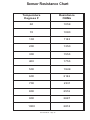
Sensor Resistance Chart
Temperature
D egrees F
R esistance
OH Ms
60
1059
70
1080
100
1143
200
1350
300
1553
400
1753
500
1949
600
2142
700
2331
800
2516
900
2697
1000
2874
Technical Manual - Page 38
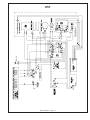
CET
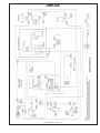
Technical Manual - Page 39
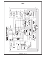
CER
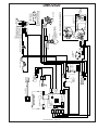
Technical Manual - Page 40
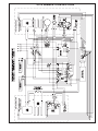
CERB
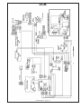
Technical Manual - Page 41
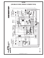
ETT304
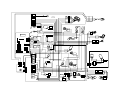
Technical Manual - Page 42
ETT365
Technical Manual - Page 43
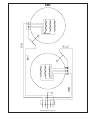
2a
RL
FL
2b
1b
1a
3b
3a
2a
INNER
COIL
1a
3a
3b
OUTER
COIL
2b
1b
RC
2b
2a
1a
3a
3b
3a
3b
3b
3a
2a
1b
2b
1a
2a
1b
2b
1a
1b
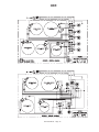
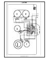
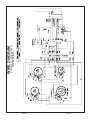
MET 365
FR
+
RR
+
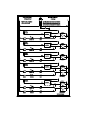
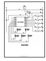
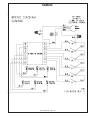
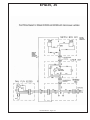
MODEL NUMBER
B
RIBBON CABLE TO
TOUCH-CONTROL
PANEL
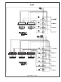
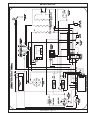
240VAC, 60Hz, 50A
ELECTRICAL CIRCUIT REQUIRED
E12
E16
E17
E14
E13
E15
E4
E1
E3
E19
J1
E10
E11
E9
E8
J2
E5
E6
E2
E7
1
2
3
4
5
6
7
L2
L1
GRD
TERMINAL
BLOCK
GROUND
FAN
P/N 65373
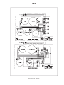
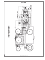
MET365 WIRING DIAGRAM
E18
B
CONTROL BOX
9500W (39.6A)
TOTAL CONNECTED LOAD
RED
BLK
GRN
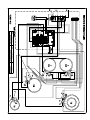
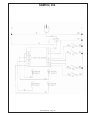
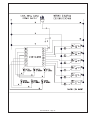
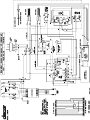
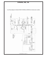
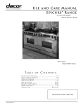
WIRING DIAGRAM
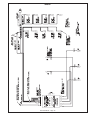
PGM365
120V, 60Hz, 0.235A
POWER SUPPLY
N
L
VERIFY PROPER OPERATION
CAUTION: LABEL ALL WIRES PRIOR TO DISCONNECTION
AFTER SERVICING
WHEN SERVICING CONTROLS. WIRING ERRORS CAN
CAUSE IMPROPER AND DANGEROUS OPERATION.
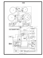
W
BK
GRN
W
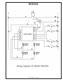
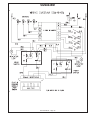
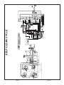
IGNITOR,
LR BURNER
RED
N
RE-IGNITOR
L1
W
NO SWITCH
BK
BK
BK
W
RESISTOR
INDICATOR LED
S1
DIODE
W
IGNITOR,
CR BURNER
RED
N
RE-IGNITOR
L1
W
NO SWITCH
BK
BK
BK
W
RESISTOR
INDICATOR LED
S2
DIODE
W
IGNITOR,
RR BURNER
RED
N
RE-IGNITOR
L1
W
NO SWITCH
BK
BK
BK
W
RESISTOR
INDICATOR LED
S3
NO SWITCH
DIODE
W
IGNITOR,
LF BURNER
RED
N
RE-IGNITOR
L1
W
NO SWITCH
BK
BK
W
BK
RESISTOR
INDICATOR LED
BK
DIODE
W
BK
RESISTOR
SIMMER LED
S4
DIODE
S4
NC SWITCH
(OPEN POSITION)
W
IGNITOR,
CF BURNER
RED
N
RE-IGNITOR
L1
W
W
NO SWITCH
BK
BK
BK
RESISTOR
INDICATOR LED
BK
DIODE
W
BK
RESISTOR
SIMMER LED
S5
DIODE
S5
NC SWITCH
(OPEN POSITION)
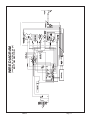
DACOR P/N 65393
ECC
Technical Manual - Page 44
GGC
Technical Manual - Page 45
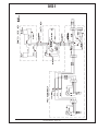
SGG304
Technical Manual - Page 46
Technical Manual - Page 47
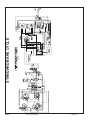
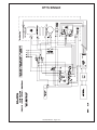
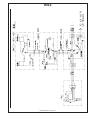
SGM304, 364
Technical Manual - Page 48
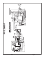
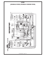
SGM362EM
Technical Manual - Page 49
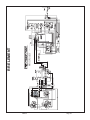
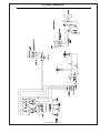
SGM464EM
Technical Manual - Page 50
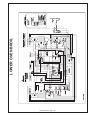
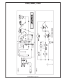
SGM466
Technical Manual - Page 51
Technical Manual - Page 52
EM4
Technical Manual - Page 53
RSE
Technical Manual - Page 54
RSG
Technical Manual - Page 55
ERSD30
Technical Manual - Page 56
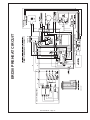
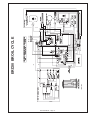
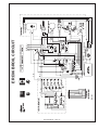
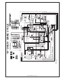
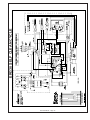
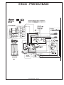
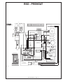
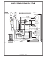
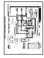
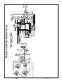
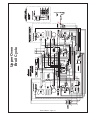
ERD30 PREHEAT CIRCUIT
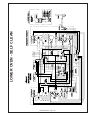
Technical Manual - Page 57
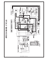
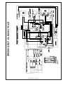
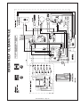
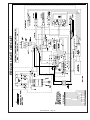
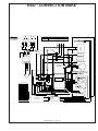
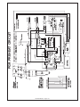
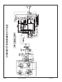
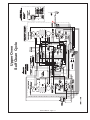
ERD30 BAKE CYCLE
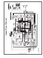
Technical Manual - Page 58
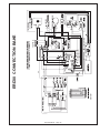
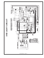
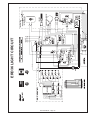
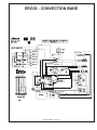
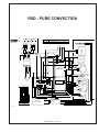
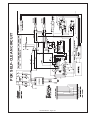
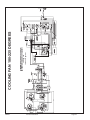
ERD30 CONVECTION BAKE
Technical Manual - Page 59
ERD30 PURE CONVECTION
Technical Manual - Page 60
ERD30 BROIL CYCLE
Technical Manual - Page 61
ERD30 SELF-CLEAN CYCLE
Technical Manual - Page 62
ERD LIGHT CIRCUIT
Technical Manual - Page 63
ERD36 PREHEAT CYCLE
Technical Manual - Page 64
ERD36 BAKE CIRCUIT
Technical Manual - Page 65
ERD36 PURE CONVECTION
ERD
Technical Manual - Page 66
ERD36 BROIL CIRCUIT
Technical Manual - Page 67
ERD36 SELF CLEAN CYCLE
Technical Manual - Page 68
ERD36 LIGHT CIRCUIT
ERD
Technical Manual - Page 69
18” OVEN PREHEAT
Technical Manual - Page 70
Technical Manual - Page 71
Note:
Cooling fan turns on between
180 and 220 degrees.
18” OVEN - BAKE CYCLE
18” OVEN CONVECTION BAKE CYCLE
Technical Manual - Page 72
18” OVEN PURE CONVECTION CYCLE
Technical Manual - Page 73
18” OVEN SELF CLEAN CYCLE
Note:
Cooling fan turns on between
180 and 220 degrees
Technical Manual - Page 74
18” OVEN LIGHT CIRCUIT
Technical Manual - Page 75
48 RANGE PREHEAT BAKE CYCLE
LARGE OVEN
Technical Manual - Page 76
48 RANGE CONV-BAKE CYCLE - LARGE OVEN
Technical Manual - Page 77
48 RANGE - 36” OVEN - PURE CONVECTION
Technical Manual - Page 78
48 RANGE BROIL CYCLE - LARGE OVEN
Technical Manual - Page 79
36” OVEN - SELF-CLEAN CYCLE
Note:
Cooling Fan turn on temp
180-220 degrees
Technical Manual - Page 80
48 RANGE LIGHT CYCLE - LARGE OVEN
Technical Manual - Page 81
ERG30 PREHEAT/BAKE CYCLE
Technical Manual - Page 82
Technical Manual - Page 83
ERG30 CONVECTION BAKE CYCLE
ERG30 SELF CLEAN CYCLE
Technical Manual - Page 84
ERG30 LIGHT CIRCUIT
Technical Manual - Page 85
ERG36 - PREHEAT/BAKE
Technical Manual - Page 86
ERG36 - CONVECTION BAKE
Technical Manual - Page 87
ERG36 - BROIL
Technical Manual - Page 88
ERG36 - LIGHT
Technical Manual - Page 89
ERG36 - SELF CLEAN
Technical Manual - Page 90
RSD - PREHEAT
W
MODEL NUMBER ELECTRICAL CIRCUIT REQUIRED TOTAL CONNECTED LOAD
DUAL FUEL RANGE
MODEL RSD30
RSD30
INDICATOR
LIGHTS
120/240VAC, 60Hz, 30A
OVEN ASSEMBLY (REF.)
5.8kW (23A)
W
W
BK
OVEN TEMPERATURE SENSOR
BK
W
R
S1
S2
S3
S4
GN
Y
BAKE
ELEMENT
2200W
BK
BK
240V
GN
W
BK
N A
4 3 2 1
BK
BK
W
L1
N
BK
BROIL ELEMENT -3500W, 240V
BK
BK
W
W
R
4 POINT RE-IGNITOR
L2
R
R
BU
S4 S3 S2 S1
CONVECTION ELEMENT -2200W, 240V
GROUND
STUD
BK
GN
R.F
BK
BK
OVEN HI TEMP LIMIT
OPEN 250∞ F.
(MANUAL RESET)
O
BK
GN
GN
L.F.
W
CONVECTION
FAN MOTOR
41W, 120V
BK
BK
BK
R.R
L.R
BK
BU
R
Y
N OL1
IGNITION
PLUGS
N.O.
COM
BR L2
BA
BN
1
BN
14
O
MAIN
RELAY
BOARD
W
SHIELD
10
11
12
13
14
1
2
3
4
5
6
7
8
9
PHASE
SWITCH
BK
GND
N
TO MAIN RELAY BOARD
COOLING BLOWER
35W, 120V
L2CLF L2 CV L2 DRLK L2
R CVL L1
BK
BK
BK
BK
BK
BK
TERM.
BLOCK
W
DOOR
LATCH
ASY
3W, 120V
LOCK
SWITCH
W
Y
BN
O
W
W
BK
MEMBRANE PIGTAIL
10
11
12
13
14
15
16
1
2
3
4
5
6
7
8
9
1
TO ERC 4800 CONTROLLER
LOW VOLTAGE CABLE
OVEN MEMBRANE
SWITCH PANEL (REF.)
ERC 4800
CONTROLLER
(REF.)
LOW VOLTAGE CABLE
16
J4 (REF.)
2
5
6
7
8
85061-1 03.22.95
Technical Manual - Page 91
BN
W
Y
O
W
OVEN
LIGHT
40W
130V
RSD PREHEAT/BAKE CYCLE
W
MODEL NUMBER ELECTRICAL CIRCUIT REQUIRED TOTAL CONNECTED LOAD
DUAL FUEL RANGE
MODEL RSD30
INDICATOR
LIGHTS
120/240VAC, 60Hz, 30A
RSD30
OVEN ASSEMBLY (REF.)
5.8kW (23A)
W
W
BK
OVEN TEMPERATURE SENSOR
BK
W
R
S1
S2
S3
S4
GN
Y
BAKE
ELEMENT
2200W
BK
BK
240V
GN
W
BK
N A
4 3 2 1
BK
BK
W
L1
N
BK
BROIL ELEMENT -3500W, 240V
BK
BK
W
W
R
4 POINT RE-IGNITOR
L2
R
R
BU
S4 S3 S2 S1
CONVECTION ELEMENT -2200W, 240V
GROUND
STUD
BK
GN
R.F
BK
BK
OVEN HI TEMP LIMIT
OPEN 250∞ F.
(MANUAL RESET)
O
BK
GN
GN
L.F.
W
CONVECTION
FAN MOTOR
41W, 120V
BK
BK
R.R
L.R
BK
BK
BU
R
Y
N OL1
IGNITION
PLUGS
N.O.
COM
BR L2
BA
BN
1
BN
14
W
SHIELD
10
11
12
13
14
1
2
3
4
5
6
7
8
9
PHASE
SWITCH
BK
GND
N
TO MAIN RELAY BOARD
O
COOLING BLOWER
35W, 120V
MAIN
RELAY
BOARD
L2 CLF L2 CV L2 DRLK L2
R CVL L1
BK
BK
BK
BK
BK
BK
TERM.
BLOCK
W
DOOR
LATCH
ASY
3W, 120V
LOCK
SWITCH
W
Y
BN
O
W
W
BK
MEMBRANE PIGTAIL
10
11
12
13
14
15
16
1
2
3
4
5
6
7
8
9
1
TO ERC 4800 CONTROLLER
LOW VOLTAGE CABLE
OVEN MEMBRANE
SWITCH PANEL (REF.)
ERC 4800
CONTROLLER
(REF.)
LOW VOLTAGE CABLE
16
J4 (REF.)
2
5
6
7
8
85061-1 03.22.95
Technical Manual - Page 92
BN
W
Y
O
W
OVEN
LIGHT
40W
130V
RSD - CONVECTION BAKE
W
MODEL NUMBER ELECTRICAL CIRCUIT REQUIRED TOTAL CONNECTED LOAD
DUAL FUEL RANGE
MODEL RSD30
INDICATOR
LIGHTS
120/240VAC, 60Hz, 30A
RSD30
OVEN ASSEMBLY (REF.)
5.8kW (23A)
W
W
BK
OVEN TEMPERATURE SENSOR
BK
W
R
S1
S2
S3
S4
GN
Y
BAKE
ELEMENT
2200W
BK
BK
240V
GN
W
BK
N A
4 3 2 1
BK
BK
W
L1
N
BK
BROIL ELEMENT -3500W, 240V
BK
BK
W
W
R
4 POINT RE-IGNITOR
L2
R
R
BU
S4 S3 S2 S1
CONVECTION ELEMENT -2200W, 240V
GROUND
STUD
BK
GN
R.F
BK
BK
OVEN HI TEMP LIMIT
OPEN 250∞ F.
(MANUAL RESET)
O
BK
GN
GN
L.F.
W
CONVECTION
FAN MOTOR
41W, 120V
BK
BK
BK
R.R
L.R
BK
BU
R
Y
N OL1
IGNITION
PLUGS
N.O.
COM
BR L2
BA
BN
1
BN
14
O
MAIN
RELAY
BOARD
W
SHIELD
10
11
12
13
14
1
2
3
4
5
6
7
8
9
PHASE
SWITCH
BK
GND
N
TO MAIN RELAY BOARD
COOLING BLOWER
35W, 120V
L2 CLFL2 CV L2 DRLK L2
R CVL L1
BK
BK
BK
BK
BK
BK
TERM.
BLOCK
W
DOOR
LATCH
ASY
3W, 120V
LOCK
SWITCH
W
Y
BN
O
W
W
BK
MEMBRANE PIGTAIL
10
11
12
13
14
15
16
1
2
3
4
5
6
7
8
9
1
TO ERC 4800 CONTROLLER
LOW VOLTAGE CABLE
OVEN MEMBRANE
SWITCH PANEL (REF.)
ERC 4800
CONTROLLER
(REF.)
LOW VOLTAGE CABLE
16
J4 (REF.)
2
5
6
7
8
85061-1 03.22.95
Technical Manual - Page 93
BN
W
Y
O
W
OVEN
LIGHT
40W
130V
RSD - PURE CONVECTION
W
MODEL NUMBER ELECTRICAL CIRCUIT REQUIRED TOTAL CONNECTED LOAD
DUAL FUEL RANGE
MODEL RSD30
INDICATOR
LIGHTS
120/240VAC, 60Hz, 30A
RSD30
OVEN ASSEMBLY (REF.)
5.8kW (23A)
W
W
BK
OVEN TEMPERATURE SENSOR
BK
W
R
S1
S2
S3
S4
GN
Y
BAKE
ELEMENT
2200W
BK
BK
240V
GN
W
BK
N A
4 3 2 1
BK
BK
W
L1
N
BK
BROIL ELEMENT -3500W, 240V
BK
BK
W
W
R
4 POINT RE-IGNITOR
L2
R
R
BU
S4 S3 S2 S1
CONVECTION ELEMENT -2200W, 240V
GROUND
STUD
BK
GN
R.F
BK
BK
OVEN HI TEMP LIMIT
OPEN 250∞ F.
(MANUAL RESET)
O
BK
GN
GN
L.F.
W
CONVECTION
FAN MOTOR
41W, 120V
BK
BK
R.R
L.R
BK
BK
BU
R
Y
N OL1
IGNITION
PLUGS
N.O.
COM
BR L2
BA
BN
1
BN
14
O
MAIN
RELAY
BOARD
W
SHIELD
10
11
12
13
14
1
2
3
4
5
6
7
8
9
PHASE
SWITCH
BK
GND
N
TO MAIN RELAY BOARD
COOLING BLOWER
35W, 120V
L2 CLFL2 CV L2 DRLK L2
R CVL L1
BK
BK
BK
BK
BK
BK
TERM.
BLOCK
W
DOOR
LATCH
ASY
3W, 120V
LOCK
SWITCH
W
Y
BN
O
W
W
BK
MEMBRANE PIGTAIL
10
11
12
13
14
15
16
1
2
3
4
5
6
7
8
9
1
TO ERC 4800 CONTROLLER
LOW VOLTAGE CABLE
OVEN MEMBRANE
SWITCH PANEL (REF.)
ERC 4800
CONTROLLER
(REF.)
LOW VOLTAGE CABLE
16
J4 (REF.)
2
5
6
7
8
85061-1 03.22.95
Technical Manual - Page 94
BN
W
Y
O
W
OVEN
LIGHT
40W
130V
RSD BROIL CYCLE
W
MODEL NUMBER ELECTRICAL CIRCUIT REQUIRED TOTAL CONNECTED LOAD
DUAL FUEL RANGE
MODEL RSD30
INDICATOR
LIGHTS
120/240VAC, 60Hz, 30A
RSD30
OVEN ASSEMBLY (REF.)
5.8kW (23A)
W
W
BK
OVEN TEMPERATURE SENSOR
BK
W
R
S1
S2
S3
S4
GN
Y
BAKE
ELEMENT
2200W
BK
BK
240V
GN
W
BK
N A
4 3 2 1
BK
BK
W
L1
N
BK
BROIL ELEMENT -3500W, 240V
BK
BK
W
W
R
4 POINT RE-IGNITOR
L2
R
R
BU
S4 S3 S2 S1
CONVECTION ELEMENT -2200W, 240V
GROUND
STUD
BK
GN
R.F
BK
BK
OVEN HI TEMP LIMIT
OPEN 250∞ F.
(MANUAL RESET)
O
BK
GN
GN
L.F.
W
CONVECTION
FAN MOTOR
41W, 120V
BK
BK
BK
R.R
L.R
BK
BU
R
Y
N OL1
IGNITION
PLUGS
N.O.
COM
BR L2
BA
BN
1
BN
14
O
COOLING BLOWER
35W, 120V
MAIN
RELAY
BOARD
SHIELD
10
11
12
13
14
1
2
3
4
5
6
7
8
9
W
GND
N
TO MAIN RELAY BOARD
PHASE
SWITCH
BK
L2 CLFL2 CV L2 DRLK L2
R CVL L1
BK
BK
BK
BK
BK
BK
TERM.
BLOCK
W
DOOR
LATCH
ASY
3W, 120V
LOCK
SWITCH
W
Y
BN
O
W
W
BK
MEMBRANE PIGTAIL
10
11
12
13
14
15
16
1
2
3
4
5
6
7
8
9
1
TO ERC 4800 CONTROLLER
LOW VOLTAGE CABLE
85061-1 03.22.95
OVEN MEMBRANE
SWITCH PANEL (REF.)
ERC 4800
CONTROLLER
(REF.)
LOW VOLTAGE CABLE
16
J4 (REF.)
2
5
6
7
8
OVEN
LIGHT
40W
130V
BN
W
Y
O
W
NOTE:
COOLING FAN COMES ON AT 180-220 DEGREES
Technical Manual - Page 95
RSD - SELF CLEAN CYCLE
W
MODEL NUMBER ELECTRICAL CIRCUIT REQUIRED TOTAL CONNECTED LOAD
DUAL FUEL RANGE
MODEL RSD30
INDICATOR
LIGHTS
120/240VAC, 60Hz, 30A
RSD30
OVEN ASSEMBLY (REF.)
5.8kW (23A)
W
W
BK
OVEN TEMPERATURE SENSOR
BK
W
R
S1
S2
S3
S4
GN
Y
BAKE
ELEMENT
2200W
BK
BK
240V
GN
W
BK
N A
4 3 2 1
BK
BK
W
L1
N
BK
BROIL ELEMENT -3500W, 240V
BK
BK
W
W
R
4 POINT RE-IGNITOR
L2
R
R
BU
S4 S3 S2 S1
CONVECTION ELEMENT -2200W, 240V
GROUND
STUD
BK
GN
R.F
BK
BK
OVEN HI TEMP LIMIT
OPEN 250∞ F.
(MANUAL RESET)
O
BK
GN
GN
L.F.
W
CONVECTION
FAN MOTOR
41W, 120V
BK
BK
R.R
L.R
BK
BK
BU
R
Y
N OL1
IGNITION
PLUGS
N.O.
COM
BR L2
BA
BN
1
BN
14
O
MAIN
RELAY
BOARD
W
SHIELD
10
11
12
13
14
1
2
3
4
5
6
7
8
9
PHASE
SWITCH
BK
GND
N
TO MAIN RELAY BOARD
COOLING BLOWER
35W, 120V
L2 CLFL2 CV L2 DRLK L2
R CVL L1
BK
BK
BK
BK
BK
BK
TERM.
BLOCK
W
DOOR
LATCH
ASY
3W, 120V
LOCK
SWITCH
W
Y
BN
O
W
W
BK
MEMBRANE PIGTAIL
10
11
12
13
14
15
16
1
2
3
4
5
6
7
8
9
1
TO ERC 4800 CONTROLLER
LOW VOLTAGE CABLE
OVEN MEMBRANE
SWITCH PANEL (REF.)
ERC 4800
CONTROLLER
(REF.)
LOW VOLTAGE CABLE
16
J4 (REF.)
2
5
6
7
8
85061-1 03.22.95
Technical Manual - Page 96
BN
W
Y
O
W
OVEN
LIGHT
40W
130V
RSD LIGHT CIRCUIT
W
MODEL NUMBER ELECTRICAL CIRCUIT REQUIRED TOTAL CONNECTED LOAD
DUAL FUEL RANGE
MODEL RSD30
RSD30
INDICATOR
LIGHTS
120/240VAC, 60Hz, 30A
OVEN ASSEMBLY (REF.)
5.8kW (23A)
W
BK
OVEN TEMPERATURE SENSOR
BK
W
W
R
S1
S2
S3
S4
GN
Y
BAKE
ELEMENT
2200W
BK
BK
GN
240V
W
N A
BK
4 3 2 1
BK
BK
W
N
R
4 POINT RE-IGNITOR
L1
L2
BK
BROIL ELEMENT -3500W, 240V
BK
BK
W
W
R
R
BU
S4 S3 S2 S1
GROUND
STUD
GN
R.F
CONVECTION ELEMENT -2200W, 240V
BK
BK
BK
OVEN HI TEMP LIMIT
OPEN 250∞ F.
(MANUAL RESET)
O
BK
GN
GN
L.F.
W
CONVECTION
FAN MOTOR
41W, 120V
BK
BK
L.R
BK
BU
MAIN
RELAY
BOARD
N.O.
COM
R
BR L2
Y
BA
1
BN
14
BN
O
COOLING BLOWER
35W, 120V
PHASE
SWITCH
BK
W
SHIELD
10
11
12
13
14
1
2
3
4
5
6
7
8
9
TO MAIN RELAY BOARD
BK
N OL1
IGNITION
PLUGS
GND
N
R.R
L2 CLFL2 CV L2 DRLK L2
R CVL L1
BK
BK
BK
BK
BK
BK
TERM.
BLOCK
W
DOOR
LATCH
ASY
3W, 120V
LOCK
SWITCH
W
Y
BN
O
W
W
BK
MEMBRANE PIGTAIL
10
11
12
13
14
15
16
1
2
3
4
5
6
7
8
9
1
TO ERC 4800 CONTROLLER
LOW VOLTAGE CABLE
OVEN MEMBRANE
SWITCH PANEL (REF.)
ERC 4800
CONTROLLER
(REF.)
LOW VOLTAGE CABLE
16
J4 (REF.)
2
5
6
7
8
85061-1 03.22.95
Technical Manual - Page 97
BN
W
O
W
Y
OVEN
LIGHT
40W
130V
PGR BAKE CIRCUIT
Technical Manual - Page 98
PGR LIGHT CIRCUIT
Technical Manual - Page 99
PGR CONV BAKE CIRCUIT
Technical Manual - Page 100
PGR PREHEAT CIRCUIT
Technical Manual - Page 101
PGR SELF-CLEAN CIRCUIT
Technical Manual - Page 102
PGR BROIL CIRCUIT
Technical Manual - Page 103
MRE30
Page 14
PART 1
(continued on following page)
MRE LADDER DIAGRAM
MRE30
Page 15
PART 2
MRE LADDER DIAGRAM
MRE30
Page 16
(continued on following page)
TOP SECTION
WIRE DIAGRAM
MRE30
Page 17
(continued on following page)
BOTTOM SECTION
WIRE DIAGRAM
MRE30
Page 20
Self Clean Cycle
SELF CLEAN CYCLE
MRE30
Page 21
Pure Convection
PURE CONVECTION CYCLE
Convection Fan
CONVECTION FAN
MRE30
Service Instructions
Page 22
MRE30
Service Instructions
Page 23
Convection Bake
CONVECTION BAKE CYCLE
MRE30
Service Instructions
Page 24
Cooling Fan
180-225 Degrees
COOLING FAN 180-225 DEGREES
Broil
BROIL CYCLE
MRE30
Service Instructions
Page 25
Bake
STANDARD BAKE CYCLE
MRE30
Service Instructions
Page 26
MRE30
Page 37
LF Element Circuit
Stay Hot Circuit
---------
LF ELEMENT CIRCUIT
MRE30
Page 38
LR Element Circuit
Stay Hot Circuit
------
RF ELEMENT
MRE30
Page 39
RF Element
Stay Hot Circuit - - - - - - -
RR ELEMENT
MRE30
Page 40
R/R Element - Power
R/R Stay Hot Circuit - - - - - - - - -
RR ELEMENT
LOWER OVEN BAKE PREHEAT
Technical Manual - Page 104
LOWER OVEN BROIL
Technical Manual - Page 105
LOWER OVEN - SELF CLEAN
Technical Manual - Page 106
Upper Oven Preheat
Technical Manual - Page 107
Upper Oven
Bake Cycle
Technical Manual - Page 108
Upper Oven
Pure Convection
Technical Manual - Page 109
Upper Oven
Broil Cycle
Technical Manual - Page 110
Upper Oven
Self Clean Cycle
Technical Manual - Page 111
CYCLE CHART - ERD48
36 “ Oven
PERCENTAGES
Preheat
B ake
Convection
B ake
B ake
100%
100%
100%
Broil
100%
Convection
F an
100%
Pure
Convection
Broil
Self-Clean
100%
100%
100%
100%
18“ Oven
PERCENTAGES
Preheat
B ake
C onvection
B ake
B ake
100%
100%
100%
B roil
100%
C onvection
F an
100%
Pure
C onvection
B roil
Self-C lean
100%
100%
100%
100%
36 “Oven
SECONDS
Preheat
B ake
C onvection
B ake
B ake
6 4 se c
6 4 se c
6 4 se c
B roil
6 4 se c
C onvection
F an
6 4 se c
Pure
C onvection
B roil
Self-C lean
6 4 se c
6 4 se c
6 4 se c
6 4 se c
18 “ Oven
SECONDS
Preheat
B ake
C onvection
B ake
B ake
6 4 se c
6 4 se c
6 4 se c
B roil
6 4 se c
1 3 se c
1 3 se c
C onvection
F an
6 4 se c
6 4 se c
Pure
C onvection
B roil
Self-C lean
6 4 se c
6 4 se c
6 4 se c
All timing is based upon a 64 second cycle. After 64 seconds a new cycle begins.
All times reflect “ON” times for elements based upon a 64 second cycle.
CYCLE CHARTS
PGR - PERCENTAGES
B ake
Preheat
B ake
C onvection
B ake
100%
100%
100%
Pure
C onvection
Self-C lean
100%
B roil
C onvection
F an
B roil
6 4 se c
100%
100%
PGR - SECONDS
B ake
Preheat
B ake
C onvection
B ake
6 4 se c
6 4 se c
6 4 se c
Pure
C onvection
Self-C lean
6 4 se c
B roil
C onvection
F an
B roil
6 4 se c
6 4 se c
6 4 se c
ERG36 - PERCENTAGES
B ake
Preheat
B ake
C onvection
B ake
100%
100%
100%
Pure
C onvection
Self-C lean
100%
B roil
C onvection
F an
B roil
100%
100%
100%
ERG36 - SECONDS
B ake
Preheat
B ake
C onvection
B ake
6 4 se c
6 4 se c
6 4 se c
B roil
C onvection
F an
Pure
C onvection
B roil
Self-C lean
6 4 se c
6 4 se c
6 4 se c
6 4 se c
All timing is based upon a 64 second cycle. After 64 seconds a new cycle begins.
All times reflect “ON” times for elements based upon a 64 second cycle.
CYCLE CHART
ERD36 - PERCENTAGES
Preheat
B ake
C onvection
B ake
B ake
100%
100%
100%
B roil
100%
C onvection
F an
100%
Pure
C onvection
B roil
Self-C lean
100%
100%
100%
100%
C onvection
Element
100%
ERD - SECONDS
Preheat
B ake
C onvection
B ake
B ake
6 4 se c
6 4 se c
6 4 se c
B roil
6 4 se c
C onvection
F an
6 4 se c
Pure
C onvection
B roil
Self-C lean
6 4 se c
6 4 se c
6 4 se c
C onvection
Element
6 4 se c
6 4 se c
SINGLE OVEN - PERCENTAGES
Preheat
B ake
C onvection
B ake
B ake
100%
81%
81%
B roil
47%
19%
19%
C onvection
F an
100%
100%
C onvection
Element
Pure
C onvection
B roil
Self-C lean
58%
100%
42%
B roil
Self-C lean
100%
100%
SINGLE OVEN - SECONDS
Preheat
B ake
C onvection
B ake
B ake
6 4 se c
5 2 se c
5 2 se c
B roil
3 0 se c
1 2 se c
1 2 se c
C onvection
F an
6 4 se c
C onvection
Element
6 4 se c
Pure
C onvection
3 7 se c
6 4 se c
2 7 se c
6 4 se c
6 4 se c
All timing is based upon a 64 second cycle. After 64 seconds a new cycle begins.
All times reflect “ON” times for elements based upon a 64 sec. cycle.
CYCLE CHART
DOUBLE OVEN - CONVECTION CELL - PERCENTAGES
Preheat
B ake
C onvection
B ake
B ake
100%
81%
81%
58%
B roil
47%
19%
19%
100%
C onvection
F an
100%
100%
C onvection
Element
Pure
C onvection
B roil
Self-C lean
100%
100%
DOUBLE OVEN - CONVECTION CELL - SECONDS
Preheat
B ake
C onvection
B ake
B ake
6 4 se c
5 2 se c
5 2 se c
3 7 se c
B roil
3 0 se c
1 2 se c
5 2 se c
3 7 se c
C onvection
F an
6 4 se c
6 4 se c
C onvection
Element
Pure
C onvection
B roil
Self-C lean
6 4 se c
6 4 se c
RSE - PERCENTAGES
Preheat
B ake
C onvection
B ake
B ake
41%
19%
84%
B roil
59%
16%
C onvection
F an
100%
100%
C onvection
Element
Pure
C onvection
B roil
Self-C lean
58%
100%
42%
B roil
Self-C lean
100%
100%
RSE - SECONDS
Preheat
B ake
C onvection
B ake
B ake
2 6 se c
1 2 se c
5 4 se c
B roil
3 7 se c
1 0 se c
C onvection
F an
6 4 se c
6 4 se c
C onvection
Element
5 2 se c
Pure
C onvection
3 7 se c
2 7 se c
6 4 se c
6 4 se c
6 4 se c
All timing is based upon a 64 second cycle. After 64 seconds a new cycle begins. All
times reflect “ON” times for elements based upon a 64 sec. cycle.
CYCLE CHARTS
ERG30 - PERCENTAGES
B ake
Preheat
B ake
Convection
B ake
100%
100%
100%
Pure
Convection
Self-Clean
100%
Broil
Convection
F an
Broil
100%
100%
100%
ERG30 - SECONDS
B ake
Preheat
B ake
Convection
B ake
6 4 se c
6 4 se c
6 4 se c
Pure
Convection
Self-Clean
6 4 se c
Broil
Convection
F an
Broil
6 4 se c
6 4 se c
6 4 se c
ERD30 - PERCENTAGES
Preheat
B ake
C onvection
B ake
B ake
100%
100%
100%
B roil
100%
C onvection
F an
100%
Pure
C onvection
B roil
Self-C lean
100%
100%
100%
100%
C onvection
Element
100%
ERD30 - SECONDS
Preheat
B ake
C onvection
B ake
B ake
6 4 se c
6 4 se c
6 4 se c
B roil
6 4 se c
C onvection
F an
6 4 se c
C onvection
Element
Pure
C onvection
B roil
Self-C lean
6 4 se c
6 4 se c
6 4 se c
6 4 se c
6 4 se c
All timing is based upon a 64 second cycle. After 64 seconds a new cycle
begins. All times reflect “ON” times for elements based upon a 64 sec. cycle.
Technical Manual - Page 117
WHT
BLK
WHT
CLOSE
GRN
OPEN
BLK
BLK
BLK
OVEN
CLEAN TEMP.
SENSOR
COOLING FAN
SWITCH
BLK
MANUAL RESET
LAMP HOLDER
40 WATT
BULB
ONLY
GRN
E3
SWITCH
9
8
7
5
3
J1
YEL
ORN
BLK
BLK
BLK
WHTBLK RED BLK BLU
E2 E1 E7 E9
E6
COM LOWER
COM CLEAN
NC
NO
NC
NO
UPPER NC
CLEAN NO
SWITCH
ERCIII ELECTRONIC CONTROL
BRN
COM
WHT
WHT
CONVECTION FAN
MOTOR
WHT
COOLING FAN
MOTOR
WHT
YEL
ORN
WHT
BRN
WHT
WHT
WHT
DACOR MODEL W305 WIRING
DIAGRAM WITH ERCIII CONTROL
6
5
P3
7
P4
P5
P1
4
3
1
2
RED
RED
WHT
ORG
YEL
WHT
BLK
WHT
L2
ORG
YEL
WHT
2
L
LIGHT
SWITCH
WHT
TERMINAL
BLOCK
OVEN PILOT
LIGHT
TERMINAL
BOARD
RED
N
RELAY
WHT
WHT
BLK
OVEN MODE
SELECTOR
BLK
BLK
BLK
P2
BLK
BLU
BLK
BLK
RED
RED
RED
BLK
L1
TEMPERATURE
SENSOR
TERM.
CAP
BLK
BLU
BLK BLK
BLK
CONV. FAN
DOOR SWITCH
ORG
BAKE TEMP.
SENSOR
OPEN
BLK
BROIL ELEMENT 3500W BAKE ELEMENT 2200W
CONVECTION ELEMENT 2200W
BLU
WHT
WHT
YEL
YEL
W305 ERCIII
CPO
Technical Manual - Page 118
CPO
Technical Manual - Page 119
CPO
Technical Manual - Page 120
CPS SINGLE CONVECTION
Technical Manual - Page 121
CPTS
(DOUBLE OVEN, SINGLE CONVECTION)
Technical Manual - Page 122
CPTS SINGLE
Technical Manual - Page 123
CPTD
(DOUBLE OVEN, DOUBLE CONVECTION)
Technical Manual - Page 124
EOG36 WIRING
Technical Manual - Page 125
DWO, EDWO, TDWO
Technical Manual - Page 126
EWO, MWO, PWO
Technical Manual - Page 127
DMO24
Technical Manual - Page 128
Technical Manual - Page 129
BLK
RED
RED
BLU
BRN
1
2
CN-C
N.O.
CN-A
N.O.
COM.
T1
1
2
CN-B
(POWER UNIT)
PRIMARY
INTERLOCK
RELAY
RY2
CN-G
(LSI UNIT)
B LU
ORG
CN-A
1 WHT
CN-B
1 PNK
2 GRN
AH SENSOR
CN-F
CONTROL PANEL
CN-F
1 BLK
2 RED
3 WHT
WHT
GRY
WHT
WHT
WHT
SECONDARY NO
INTERLOCK
SWITCH
COM.
N.O.
WHT
COM.
GRN
GRN
MONITOR
SWITCH
N.C.
RED
to Oven cavity
COM.
DOOR
SENSING
SWITCH
RED
BLK
MONITOR
FUSE
&
HOLDER
GRN
PNK
WHT
WHT
CAVITY TEMP. FUSE
WHT
TURNTABLE
MOTOR
WHT
BRN
WHT
WHT
RED
RED
OVEN LAMP
AND SOCKET
RED
MAGNETRON TEMP. FUSE
POWER SUPPLY
CORD 120V 60Hz
N
ORG
FAN MOTOR
MAGNETRON
POWER
TRANSFORMER
H.V. RECTIFIER
HIGH VOLTAGE
WIRE A
HIGH
VOLTAGE
CAPACITOR
HIGH VOLTAGE COMPONENTS
WHT
NOTE:
The neutral (WHT/GRY) wire must
be connected to the terminal with
"N" mark on the power supply
cord.
H
ORG
NOTE:
Hot (ORG) wire must be
connected to the terminal
with blue mark on the oven
light socket.
BLUE MARK
ORG
GRY
WHT
NOTE:
The grounding conductor of
the power supply cord has
been grounded by power
supply cord fixing screw.
The screw must always be
kept tight.
RED
DMO2420
Technical Manual - Page 130
1
9
RY4
RY3
RY2
RY1
CN-C
CN-C
7
CN-A
1
1
3
CN-F
(POWER UNIT)
CN-B
IC1
(LSI UNIT)
2 12
12
CN-E
1
CN-G
3
1
CONTROL UNIT
YLW
WHT
BLK
BLK
1 WHT
2
5
4
3
YLW
RED
8
7
6
ORG
9
CN-B
2 RED
1 RED/ORG
1 RED
2
5
4
3
6
7
CN-A
STOP SWITCH
HARNESS
1 RED
2 GRN
CN-E
BLK
3 YLW
2
1 GRN
SENSOR GROUND WIRE
GRN
AH SENSOR
to chassis support
CN-F
1 BLK
2 RED
3 WHT
N.O.
COM.
SECONDARY
INTERLOCK
SWITCH
MONITOR
SWITCH
BLK
N.C.
BLK
FUSE &
HOLDER
RED
BLK
COM.
PRIMATY
INTERLOCK SWITCH
N.O.
GRY
GRY
WHT
WHT
COM.
WHT
WHT
QRG
QRG
RED
BLK
COM.
GRN
RED
STOP SWITCH
N.O.
GRN
to Chassis support right
WHT
WHT
G
R
Y
BLK
WHT
RED
RED
3 BLK
RED
WHT
RED
ORG
RED
MAGNETRON
TEMPERATURE
FUSE
RED
OVEN LAMP & SOCKET
Blue
Marking
Power Supply
cord 120V 60Hz
RED
BLU
To inverter
angle
2
BLK
YLW
3
1
GRN
M
AC3 A
N
C
F
MAGNETRON
FA
FA
Earth
F
INVERTER
UNIT
RR
E E
DD
HIGH VOLTAGE
WIRE ASSEMBLY
HIGH VOLTAGE COMPONENTS
WHT
INVERTER
WIRE ASSEMBLY
GRN
BLK
WHT 2 WHT
GRN 1 GRN
PWM WIRE ASSEMBLY
WHT 2 BLU
RED 1 RED
ORG
ORG
WHT
ORG
YLW
STIRRER MOTOR
FAN
MOTOR
HOOD FAN
THERMAL
CUT-OUT
WHT
WHT
RED
RED
GRY
Blue Marking
HOOD LAMPS
& SOCKETS
WHT
WHT
BLU
OVEN
THERMAL
CUT-OUT
BLK
HOOD FAN MOTOR
WHT
TURNTABLE
MOTOR
GRN
RED 5 RED
YLW 4 YLW
WHT 3 WHT
BLK 2 BLK
BLU 1 BLU
6
PMOR
DCM
Technical Manual - Page 131
EHDR, ILB8
Technical Manual - Page 132
EHD30, 36
Technical Manual - Page 133
EHD42, 48, 54
Technical Manual - Page 134
RV
Technical Manual - Page 135
IVS1
Technical Manual - Page 136
IVS2
Technical Manual - Page 137
Technical Service
950 S. Raymond Ave.
Pasadena, CA 91105
Part # 95106 REV.8.7.02