1
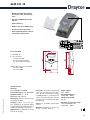
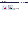
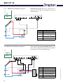
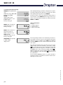
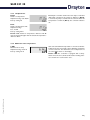
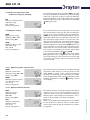
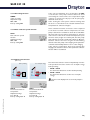
Drayton SHR 521 20 49000720 *49000720* SHR 521 20 Installation Commissioning Operation Fault finding Examples B manual Thank you for buying a Drayton product. Please read this manual carefully to get the best perfomance from this unit. SHR 521 20 Contents Disclaimer ............................................................................2 Safety Regulations ...............................................................2 Technical data and function ...............................................3 1. Installation .............................................................5 1.1 Mounting .................................................................................. 5 1.2 Electrical wiring ...................................................................... 5 1.2.1 Standard solar system ........................................................... 6 1.2.2 Solar system and back-up heating ...................................... 6 2. Operation and function ........................................7 2.1 Adjustment buttons .............................................................. 7 2.2 System-screen display ........................................................... 7 2.2.1 Channel indication ................................................................. 7 2.2.2 Tool bar .................................................................................... 7 2.2.3 2.3 2.3.1 2.3.2 3. 4. 4.1 4.1.1-6 4.1.7-17 5. 5.1 6. Security advice Please pay attention to the following security advice in order to avoid danger and damage to people and property. Instructions Attention should be paid - to the statutory provisions for prevention of industrial accidents, - to the statutory provisions for environmental protection, - to the Health and Safety at Work Act 1974 - to Part P of the Building Regulations 2005 - to BS7671 Requirements for electrical installations and relevant safety regulations of DIN, EN, DVGW, TRGI, TRF and VDE. This instruction is exclusively addressed to authorised skilled personnel. - Only qualified electricians should carry out electrical works. - Initial installation should be effected by named qualified personnel Declaration of conformity We, Invensys Controls Europe, declare under our sole responsibility that our product SHR 52120 complies with the following standards: EN 55 014-1 EN 60 730-1 According to the regulations of the above directives, the product is labelled with : 89/336/EWG 73/ 23/EWG © Drayton 06334 SHR 521 20.monen.indd System screen ......................................................................... 8 Flashing symbols ..................................................................... 8 System-Screen flashing symbols ......................................... 8 Flashing symbols ..................................................................... 8 Commissioning ......................................................9 Control parameter and indication channels ... 10 Channel overview ................................................................ 10 Indication channels .............................................................. 11 Adjustment channels ........................................................... 12 Tips for fault finding ........................................... 17 Miscellaneous ........................................................................ 18 Accessories ......................................................... 20 |2 SHR 521 20 • Backlit multifunction display to monitor solar thermal systems • Up to 4 Pt1000 temperature sensors • Heat balancing • Stylish, easy-to-install housing • Simple 3-button operation • Solar operating hours counter and thermostat function ! Parts included: 1 x SHR 521 20 1 x accessory bag 1 x spare fuse T4A 2 x screws and wall plugs 4 x cable clamps and screws © Drayton 06334 SHR 521 20.monen.indd Additionally enclosed in the full kit: 1 x sensor FKP6 1 x sensor FRP6 Technical data Housing: plastic, PC-ABS and PMMA Protection type: IP 20 / DIN 40050 Ambient temp.: 0 ... 40 °C Size: 172 x 110 x 46 mm Mounting: wall mounting, panels mounting is possible Display: System screen for system visualisation, 16-segment display, 7-segment display, 8 symbols for system status and operating control lamp Operation: by 3 pushbuttons on the front of the housing Functions: Temperature differential controller with optional system functions. System monitoring according to BAW-guidelines, operating hours counter for solar pump, tube collector special function, as well as heat quantity balancing. Inputs: for 4 Pt1000 temperature sensors Outputs: depending on version, see section „controller versions“ Power supply: 220 ... 240V~ Switching Capacity: 4 (2) A 220 ... 240V~ Mode of operation: Typ 1.b Breaking capacity per relay: electromechanical relay: 4 (2) A 220 ... 240V~ 3| SHR 521 20 Examples SHR 521 20 Standard solar systems Solar systems with dual-mode DHW cylinder © Drayton 06334 SHR 521 20.monen.indd Please find detailed connection diagramms for these systems in chapter 1. |4 SHR 521 20 1. Installation display Warning! Switch-off mains supply before opening the housing. 1.1 Mounting cover pushbuttons cable conduits in the clamps can fuse 4A hanging The unit must only be located indoors. It is not suitable for installation in hazardous locations and should not be sited near to any electromagnetic field.The controller must additionally be equipped with an all-polar gap of at least 3 mm or with a gap according to the relevant installaton regulations, e.g. LS-switches or fuses. Please ensure that sensor cables and AC power cables are kept well apart. 1. Unscrew the cross-head screw of the cover and remove it from the housing. 2. Mark the upper fastening point on the wall and insert the enclosed wall plug and screw. 3. Hang the housing at the upper fastening point and mark the lower fastening point on the wall (hole pitch 130 mm), afterwards put the lower wall plug. 4. Fix the housing on the wall. fixation 1.2 Electrical wiring fuse T4A 220 ... 240 V~ R1 2 (1) A (220 ... 240) V~ R2 2 (1) A (220 ... 240) V~ Temp. Sensor Pt1000 S1 1 2 3 S2 4 S3 5 © Drayton 06334 SHR 521 20.monen.indd Sensor terminals 6 S4 7 8 12 13 14 N R2 N R1 N L 15 16 17 18 19 20 earth terminals output terminals mains terminals The power supply to the controller must only be made by an external mains switch (last step of installation!) and the mains voltage must be 220 ... 240 Volt (50...60 Hz). Flexible lines are to be fixed at the housing by enclosed cable clamps and screws. The controller is equipped with 2 relays to which the outputs e.g. pumps, valves etc. can be connected: • Relay 1 18 = line R1 17 = neutral N 13 = earth terminal • Relay 2 16 = line R2 15 = neutral N 14 = earth terminal The temperature sensors (S1 up to S4) will be connected to the following terminals regardless of polarity: 1 / 2 = Sensor 1 (e.g. Sensor collector 1) 3 / 4 = Sensor 2 (e.g. Sensor store 1) 5 / 6 = Sensor 3 (e.g. Sensor TSPO) 7 / 8 = Sensor 4 (e.g. Sensor TRL) The power supply is connected to the terminals: 19 = neutral N 20 = Line L 12 = earth terminal Electrostatic discharge can damage electronic components! Dangerous voltage on contact! 5| SHR 521 20 1.2.1 Allocation of terminals for system 1 Standard solar system with 1 store, 1 pump and 3 sensors. The sensor S4 / TRF can optionally be used for heat quantity balancing. Arr 1 S1 R1 Symbol S1 S2 S3 S3 S2 S4 / TRF S4 / TRF R1 Specification Collector sensor Store sensor lower Store sensor upper (optional) Sensor for heat quantity measurement (optional) Solar pump Solar system and dual-mode DHW cylinder with 1 store, 3 sensors and backup-heating.The sensor S4 / TRF can optionally be used for heat quantity balancing. 1.2.2 Allocation of terminals for system 2 Arr 2 R1 S4 / TRF S3 S2 R2 Symbol S1 S2 S3 S4 / TRF R1 R2 |6 Specification collector sensor store sensor lower store sensor upper sensor for heat quantity balancing (optional) solar pump pump for heat exchange © Drayton 06334 SHR 521 20.monen.indd S1 SHR 521 20 2. Operation and function 2.1 Pushbuttons for adjustment backwards forward 2 3 1 The controller is operated by 3 pushbuttons below the display. The forward-key (1) is used for scrolling forward through the menu or to increase the adjustment values. The backwards-key (2) is accordingly used for the reverse function. To confirm the current mode, hold down button 1 for 2 seconds. If an adjustment value is shown on the display, SEt is indicated. In this case you can press the key „Set“ (3) in order to change into input mode. Select a mode by keys 1 and 2 Press key 3, so that „SEt“ flashes Adjust the value by keys 1 and 2 Press key 3, so that „SEt“ permanently appears, the selected value is now saved. SET (selection / adjustment mode) 2.2 System monitoring display ! The system monitoring display consists of 3 blocks: mode indication, tool bar and system screen (active system scheme). Complete monitoring-display 2.2.1 Mode indication only mode indication The mode indication consists of two lines. The upper line is an alphanumeric 16-segment display, in which mainly the mode names / menu items are shown. In the lower 7-segment display, the channel values and the adjustment parameter are indicated. Temperatures and temperature differences are indicated in or . 2.2.2 Tool bar The additional symbols of the tool bar indicate the current system status. Symbol standard flashing relay 1 active only tool bar relay 2 active maximum store limitation active / maximum store temperature exceeded © Drayton 06334 SHR 521 20.monen.indd antifreeze- function activated collector cooling function or recooling function active collector minimum limitation or antifreeze function active collector security shutdown or store security shutdown active + sensor defect + manual operation active an adjustment channel is changed SET-mode 7| SHR 521 20 2.2.3 System screen The system screen (active system scheme) shows the schemes selected on the controller. It consists of several system component symbols, which are - depending on the current status of the system - either flashing, permanently shown or hidden. only system screen Sensors Sensor store upper Collector 2 Heating Collector 1 Valves Valves Pumps Sensor Additional symbol for operation of the burner Store heat exchanger Store Store 2 or back-up heating (with additional symbol) Temperature sensor Collectors with collector sensor Store 1 and 2 with heat exchanger 3-way valves The flow direction or the current breaking capacity are always shown. Heating circuit Pump Back-upheat with burner symbol 2.3.1 System screen flashing symbols 2.3.2 LED flashing codes |8 • Pumps are flashing during starting phase • Sensors are flashing if the respective sensor-mode is selected. • Sensors are flashing quickly in case of sensor defect. • Burner symbol is flashing if back-up heat is activated. Constantly green: everything functioning correctly Red/green flashing: initialisation phase manual operation Red flashing: sensor defect (sensor symbol is flashing quickly) © Drayton 06334 SHR 521 20.monen.indd 2.3 Flashing symbols SHR 521 20 3. Commissioning To commission you have to adjust the solar thermal system Operation control lamp forward backwards 2 3 1. Ac power supply must be activated.The controller passes an initialisation phase in which the operating control lamp flashes red and green. When the initialisation is complete, the controller is in automatic operation with factory settings. The default system scheme is Arr 1. 2. - select Arr 1 - change into -mode (see 2.1) - select the system scheme by Arr-characteristics - adjustment is saved by pressing button Now the controller is ready for operation and should allow optimum operation of the solar system by the factory settings. SET (Selection / Adjustment mode) Arr 1 Arr 2 System types: Arr 1 : standard solar system © Drayton 06334 SHR 521 20.monen.indd Arr 2 : solar system with back-up heating 9| SHR 521 20 4. Control parameters and menu mode 4.1 Mode-overview Legend: x Corresponding mode is only available if the option heat quantity measurement is activated (OWMZ). Corresponding mode is available. x* Corresponding mode is available if the appropriate option is activated. MEDT Please note: S3 and S4 are only indicated if sensors are connected. mode Arr specification 1 2* COL x x TST x Corresponding mode is only available if the option heat quantity measurement is deactivated (OWMZ). The mode antifreeze content (MED%) is only shown if a medium other than water or Tyfocor LS / G-LS (MEDT 0 or 3) is used. The adjustment is only appropriate when using other types of antifreeze. page mode Arr 1 2 specification page Temperature collector 1 11 OCX x x Option collector cooling collector 1 14 Temperature store 1 11 CMX x* x* Maximum temperature collector 1 14 OCN x x Option minimum limitation collector 1 14 CMN x* x* Minimum temperature collector 1 14 TSTL x Temperature store 1 lower 11 TSTU x Temperature store 1 upper 11 S3 x Temperature sensor 3 11 TRF Temperature return flow 11 S4 Temperature sensor 4 11 hP x Operating hours relay 1 11 OCF x x Option antifreeze collector 1 14 CFR x* x* Antifreeze temperature collector 1 14 h P1 x Operating hours relay 1 11 OREC x x Option recooling 15 h P2 x Operating hours relay 2 11 O TC x x Option tube collector 15 kWh Heat quantity kWh 12 AH O x Switch-on temp. for thermostat 1 15 MWh Heat quantity MWh 12 AH F x Switch-off temp. for thermostat 1 15 System 9 OHQM x Option WMZ 12 Arr 1-2 DT O x x Switch-on temperature difference 13 FMAX Maximum flow 12 DT F x x Switch-off temperature difference 13 MEDT Antifreeze type 12 S MX x x Maximum temperature store 1 13 MED% EM x x emergency temperature collector 1 14 HND x x Manual operation relay 1 16 HND2 x x Manual operation relay 2 16 LANG x x Language 16 PROG XX.XX Program number VERS X.XX Version number 12 © Drayton 06334 SHR 521 20.monen.indd MEDT MEDT Antifreeze content | 10 SHR 521 20 4.1.1 Indication of collector temperatures COL: Collector temperature display range: -40 ...+250 °C 4.1.2 Shows the current store temperature. • TST : store temperature (1-store-system) • TSTL : store temperature lower • TSTU : store temperature upper Indication of sensor 3 and sensor 4 S3, S4: Sensor temperatures display range: -40 ...+250 °C 4.1.4 • COL : collector temperature (1-collector-system) Indication of store temperatures TST,TSTL,TSTU: Store temperatures display range: -40 ...+250 °C 4.1.3 Shows the current collector temperature. Shows the current temperature of the corresponding additional sensor (without control function). • S3 : temperature sensor 3 • S4 : temperature sensor 4 Please note: S3 and S4 are only indicated if the temperature sensors are connected (shown). Indication of other temperatures TRF: other measured temperatures display mode: -40 ...+250 °C Shows the current temperature of the sensor. • TRF : temperature return flow 4.1.5 Operating hours counter h P / h P1 / h P2: Operating hours counter display mode The operating hours counter adds up the solar operating hours of the respective relay (h P / h P1 / hP2).Total hours are shown on the display. The total operating hours can be reset. When one operating hours mode is selected, the symbol is permanently shown on the display. The button SET (3) must pressed for approx. 2 seconds in order to get back into the RESET mode of the counter.The display-symbol is flashing and the operating hours will be set to 0. In order to finish the RESET procedure, the button must be pressed in order to confirm. © Drayton 06334 SHR 521 20.monen.indd To interrupt the RESET procedure, no button should be pressed for about 5 seconds. The controller returns automatically into the menu mode. 11 | SHR 521 20 4.1.6 Heat quantity balancing OHQM:Heat quantity balancing Adjustment range: OFF ...ON Factory setting: OFF FMAX: Volume flow in l/min Adjustment range 0 ... 20 in steps of 0,1 Factory setting 6,0 MEDT: Type of antifreeze Adjustment range 0 ...3 Factory setting 1 Heat quantity balancing is possible for all systems in conjunction with a flowmeter. You just have to activate the option heat quantity balancing in the mode OHQM. The flow volume read by the flowmeter (l/min) must be selected in the mode FMAX. Antifreeze type and concentration of the heat transfer medium are indicated in modes MEDT and MED%. Type of antifreeze: 0 : water 1 : propylene glycol 2 : ethylene glycol 3 : Tyfocor® LS / G-LS MED%: Concentration of antifreeze in (Vol-) % MED% is blinded out by MEDT 0 and 3. Adjustment range 20 ...70 Factory setting 45 kWh/MWh:Heat quantity in kWh / MWh display mode The heat quantity transferred is calculated by the flow volume and the reference sensors of feed flow S1 and return flow S4. It is shown in kWh in mode kWh and in MWh in the mode MWh. The sum of both modes form the total heat output. The total heat quantity can be reset. As soon as one of the display modes of the heat quantity is selected, the symbol is permanently shown on the display. The button SET (3) must be pressed for approx. 2 seconds to return to the RESET mode of the counter. The display-symbol is flashing and the value for heat quantity will be set to 0. To finish the RESET-procedure, the button must be pressed for confirmation. © Drayton 06334 SHR 521 20.monen.indd To interrupt the RESET-procedure, no button should be pressed for about 5 seconds. The controller returns automatically into menu mode. | 12 SHR 521 20 4.1.7 ∆T-adjustment DT O: Switch-on temperature Adjustment range 1,0...20,0 K Factory setting 6.0 Basically the controller works in the same way as a standard differential controller. If the switch-on difference (DT O) is reached, the pump is activated. If the selected switch-off temperature is underrun (DT F), the controller switches off. DT F: Switch-off temperature diff. Adjustment range 0,5 ... 19,5 K Factory setting 4.0 K Please note: Switch-on temperature difference DT O must be at least 1 K higher than the switch-off temperaturedifference DT F. 4.1.8 Maximum store temperature If the selected maximum temperature is exceeded, a further loading of the store is stopped so that a damaging overheating can be avoided. If the maximum store temperature is exceeded, is shown on the display. Please note: The controller is equipped with a safetyswitch-off of the store, which avoids a further loading of the store if 95 °C are reached at the store. © Drayton 06334 SHR 521 20.monen.indd S MX: Maximum store temp. Adjustment range 2..95 °C Factory setting 60 °C 13 | SHR 521 20 4.1.9 Collector temperature limit Collector emergency shutdown EM: Collector temperature limit Adjustment range 110 ... 200 °C, Factory setting 140 °C 4.1.10 System cooling OCX: Option system cooling Adjustment OFF ... ON Factory setting OFF CMX: Maximum collector temp. Adjustment range 100 ...190 °C Factory setting120 °C If the selected collector limit temperature (EM) is exceeded, the solar pump (R1/R2) is deactivated to avoid overheating of the solar components (collector emergency shutdown). The limit temperature is set to 140 °C but it can be changed within the adjustment range of 110 ...200 °C. In the display (flashing) is shown. If the selected maximum store temperature is reached, the solar system switches off. If then the collector temperature rises to the selected maximum collector temperature (CMX), the solar pump remains activated until the collector temperature falls below the temperature limit value. The store temperature might continue to rise (up to the maximum store temperature), but only until 95 °C (emergency shutdown of the store). If the store temperature is higher than the maximum store temperature (S MX) and the collector temperature is lower by at least 5 K than the store temperature, the solar system remains activated until the store is again cooled down by the collector and the pipes to the selected maximum temperature (S MX). In case of active system cooling is shown on the display (flashing). Thanks to the cooling function the solar system can be kept running for longer periods on hot summer days and cooling of the collector and the heat transfer medium is ensured as well. 4.1.11 Option minimum collector limit OCN: Minimum collector limit Adjustment range OFF / ON Factory setting OFF CMN: Minimum collector temperature adjustment range -10 ... 90 °C Factory setting 10 °C The minimum collector temperature is a minimum switching temperature, which must be exceeded to allow the solar pump (R1/R2) to switch on. The minimum temperature will prevent overswitching of the solar pump (or solid fuel boiler charging pumps) at low collector temperatures. If the minimum temperature is underrun, (flashing) is shown on the display. OCF: Antifreeze function Adjustment range OFF / ON Factory setting OFF CFR: Antifreeze temperature Adjustment range -10 ...10 °C Factory setting 4,0 °C | 14 The antifreeze function activates the loading circuit between collector and store if the selected antifreeze function is underrun in order to protect the medium from freezing or thickening. If the selected antifreeze temperature is exceeded by 1 °C, the loading circuit will be deactivated. Please note: As there is only a limited heat quantity of the store available for this function, the antifreeze function should only be used in regions with few days of temperatures around the freezing point. © Drayton 06334 SHR 521 20.monen.indd 4.1.12 Option antifreeze function SHR 521 20 4.1.13 Recooling function If the selected maximum store temperature (S MX) is reached, the solar pump remains activated to avoid overheating the collector. The store temperature might continue to increase but only up to 95 °C (emergency shutdown of the store). In the evening the solar system continues running until the store is cooled down to the selected maximum store temperature via collector and pipes. OREC: option recooling adjustment range OFF ...ON Factory setting: OFF 4.1.14 Tube collector special function O TC: Tube collector special function Adjustment range: OFF ...ON Factory setting: OFF If the controller measures an increase of 2 K compared to the latest recorded collector temperature, the solar pump is switched on to 100 % for about 30 seconds. After this period the current collector temperature is stored as new reference value. If the measured temperature (new reference value) is again exceeded by 2 K, the solar pump again switches-on for 30 seconds. If the switch-on difference between collector and store is again exceeded during runtime of the solar pump or the stopping of the system, the controller automatically switches over to solar charging. If the collector temperature drops by 2 K during this stoppage, the switch-on value for the special tube collector function will be recalculated. 4.1.15Thermostat function (Arr = 2) back-up heating use of surplus energy The thermostat function works independently from the solar operation and can be used for use of surplus energy back-up heating. • AH O < AH F the thermostat function is used for back-up heating • AH O > AH F the thermostat function is used for use of surplus energy is shown on the display if the second relay output is activated. AH F: Thermostat switch-off temperature Adjustment range: 0,0 ...95,0 °C Factory setting: 45,0 °C © Drayton 06334 SHR 521 20.monen.indd AH O: Thermostat switch-on temperature Adjustment range: 0,0 ...95,0 °C Factory setting: 40,0 °C 15 | SHR 521 20 4.1.16 Operating mode HAND / HND1 / HND2: Operating mode Adjustment range: OFF, AUTO, ON Factory setting: AUTO For commissioning and service work the operating mode of the controller can be manually selected by selecting the adjustment value HAND / HND1 / HND2, in which the following adjustments can be made: • HAND / HND1 / HND2 Operating mode OFF : relay off (flashing) + AUTO : relay in automatic operation ON : relay on (flashing) + 4.1.17 Language The menu language can be selected in this channel. • • • • dE En It FR : : : : German English Italiano French © Drayton 06334 SHR 521 20.monen.indd LANG: Adjustment of language Adjustment range: dE, En, It, FR Factory setting: En | 16 SHR 521 20 5.Tips for fault finding can fuse T4A T4A If a malfunction occurs, a notification is given on the display of the controller: 220 ... 240 V~ R1 2 (1) A (220 ... 240) V~ R2 2 (1) A (220 ... 240) V~ Temp. Sensor Pt1000 S1 1 2 3 S2 4 S3 5 6 S4 7 8 12 13 14 Warning symbol N R2 N R1 N L 15 16 17 18 19 20 Operating control lamp Operating control lamp flashes red. On the display the symbol and the symbol appear. Sensor defect. An error code is shown on the relevant sensor mode instead of a temperature. 888.8 - 88.8 open circuit. Check the line. Short-circuit. Check the cables. Operating control lamp off The power supply to the controller should be checked if the control lamp goes out. no o.k. The can fuse of the controller is defective. It can be replaced after removal of the front cover (spare fuse is enclosed in the accessory bag). © Drayton 06334 SHR 521 20.monen.indd Pt1000 temperature sensors when disconnected can be checked with an ohmmeter. In the following the resistance values corresponding to different temperatures are listed. Resistance values of the Pt1000-sensors 17 | SHR 521 20 5.1Various: Pump is overheated, there is no heat transfer from collector to the store, feed flow and return flow are equally warm, perhaps also bubble in the lines. Pump starts for a short moment, switches off, switches on again, etc. (“controller hunting“) Air in the system? Is the temperature difference at the controller too small? no yes Drain the system; increase system pressure to at least static primary pressure plus 0,5 bar; if necessary continue to increase, switch the pump for a short time off and on. Is the collector circuit blocked at the dirt trap? no Wrong position of the collector sensor? no yes yes yes Clean the dirt trap Check collector special function. Change ∆T on and ∆Toff accordingly. no o.k. Mount the collector sensor at solar feed flow (warmest collector output); use the immersion sleeve of the respective collector. Pump starts up very late and soon stops working soon. The temperature difference between store and collector increases enormously during operation; the collector circuit cannot dissipate the heat. Switch-on temperature difference ∆Ton too high? Collector circuit pump defect ? no yes Change ∆T on and ∆Toff accordingly. yes Control / replace Heat exchanger calcified? Collector sensor unfavourable placed (e.g. contact sensor instead of immersion sleeve sensor? yes no no yes Decalification If necessary activate tube collector function. Heat exchanger blocked? o.k. yes Cleaning Heat exchanger too small? yes | 18 New calculation of the dimension. © Drayton 06334 SHR 521 20.monen.indd no SHR 521 20 a b Stores are cooled during the night. Control the return flow preventer in warm water circulation- o.k. Does collector circuit pump run during the night? no yes Collector temperature is at night higher than ambient temperature. no yes yes Check the controller functions correctly no Is store insulation close enough to the store? yes no no Warm water outflow upwards? no yes Increase the insulation. The solar circuit pump does not work although the collector is obviously warmer than the store. Replace or intensify the insulation. Does the control LED flash? yes Insulate connections. Change connection and let the water flow sidewards or through a siphon (bow downwards); less store losses now? no Does warm water circulation run for a very long time? © Drayton 06334 SHR 521 20.monen.indd no yes Switch-off the circulation pump and the blocking valve for 1 night; less store losses? yes no Cleaning or replacement. Check the return flow preventer in feed flow and return flow for functional efficiency. Are the store connections insulated? yes no The gravitation circulation in the circulation line is too strong; insert a stronger return flow preventer or an electrical 2-way valve behind the circulation pump; the 2-way valve is open in pump operation, otherwise it is closed, connect pump and 2-way Is store insulation sufficient? yes Please also check further pumps which are connected to the solar store. yes no Does the pump start up in manual operation? no yes valve in parallel; activate the circulation again! There is no current; check fuses / replace them and check power supply. The selected temperature difference for starting the pump is too high; choose suitable setting Is the flow of the pump seen by the controller? Is the pump stuck? no yes yes o.k. Put the pump into operation by means of a screwdriver; is there flow now ? Use the circulation pump with timer and switch-off thermostat (energy efficient circulation) Check the pumps of the backup heating circuit according to nightly run and defect return flow preventer; problem solved? no Are the fuses of the controller o.k.? no Replace the fuses. Is the pump defective ? replace it. yes Controller seems to be defective - replace it. no a b 19 | SHR 521 20 6. Accessories Sensors Our product range includes high-precision platinum temperature sensors, flatscrew sensors, ambient temperature sensors, indoor temperature sensors, cylindrical clip-on sensors and irradiation sensors, which can be used as full sensors with sensor pocket. Overvoltage protection We highly recommend installing overvoltage protection in order to avoid overvoltage damage to the collector (e.g. by lightning). Flowmeter If you are interested in heat quantity balancing, you need a flowmeter for measuring the volume flow in your system. Invensys Controls Europe Sales: +44 (0) 845 / 130 5522 Technical: +44 (0) 845 / 130 5522 Fax: +44 (0) 845 / 130 0622 E-mail: [email protected] www.draytoncontrols.co.uk Please note: The design and the specifications are to be changed without notice. The illustrations may differ from original product. | 20 © Drayton 06334 SHR 521 20.monen.indd Distributed by: