1
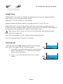
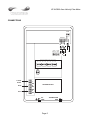
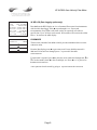
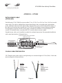
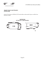
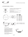
Tel: +44 (0)191 490 1547
Fax: +44 (0)191 477 5371
Email: [email protected]
www.micronicsflowmeters.com
Website: www.heattracing.co.uk
www.thorneanderrick.co.uk
USER'S GUIDE
Installation & Operation
Instructions
Area-Velocity Flow Meter
Model UF AV5000
Manual Series B.1.4
UF AV5000 Area-Velocity Flow Meter
Note: This page has been left blank intentionally.
Page 2
UF AV5000 Area-Velocity Flow Meter
INDEX
CONNECTIONS ................................................................................................ 4 FUNCTION TEST .............................................................................................. 4 KEYPAD SYSTEM............................................................................................ 6 CALIBRATION MENU ..................................................................................... 8 MESSAGE .......................................................................................................... 9 STATUS ............................................................................................................. 9 PASSWORD..................................................................................................... 10 UNITS/MODE .................................................................................................. 11 CALIBRATION................................................................................................ 12 RELAY PARAMETERS .................................................................................. 16 SPECIAL FUNCTIONS ................................................................................... 17 INSTALLATION - SENSOR LOCATION ...................................................... 19 ENCLOSURE INSTALLATION ..................................................................... 23 FIELD TROUBLESHOOTING........................................................................ 24 APPLICATIONS HOTLINE ............................................................................ 26 PRODUCT RETURN PROCEDURE............................................................... 27 AREA-VELOCITY FLOW DATA SHEET ..................................................... 28 APPENDIX A – OPTIONS............................................................................... 31 DATA LOGGING (OPTIONAL)......................................................................... 36 SPECIFICATIONS........................................................................................... 39 IMPORTANT NOTE: This instrument is manufactured and calibrated to meet product specifications.
Please read this manual carefully before installation and operation. Any unauthorized repairs or
modifications may result in a suspension of the warranty.
Available in Adobe Acrobat pdf format
Page 3
UF AV5000 Area-Velocity Flow Meter
CONNECTIONS:
POWER INPUT: 100 to 240 VAC 50/60Hz. No adjustments are necessary for voltages within this
range. Connect L (Live) N (Neutral) and AC Ground.
Optional DC: 9-32 VDC. Connect to + and -terminals.
Optional Thermostat and Heater modules are available rated for 115 VAC or 230 VAC.
IMPORTANT NOTE: AC power input and relay connection wires must have conduit entry to the
instrument enclosure. Installation requires a switch, overcurrent fuse or circuitbreaker in the building (in
close proximity to the equipment) that is marked as the disconnect switch.
!
Risk of electric shock. Loosen cover screw to access connections. Only qualified personnel
should access connections.
Note: Use of instrumentation over 40°C ambient requires special field wiring.
Note: User replaceable fuse is 2 Amp 250V (T2AL250V).
FUNCTION TEST:
Connect the sensor to the TDCR terminals as shown below, then apply
power. Allow 30 seconds for the UF AV5000 to initialize.
GOOD
A. Place QZ02L sensor (flat to the bottom) in a bucket of water
about 6” deep and select Level mode (from UNITS/MODE
menu) to see a level reading.
B. Select Velocity mode and stir the water to see a velocity
reading.
Page 4
BAD
UF AV5000 Area-Velocity Flow Meter
CONNECTIONS
+ –
+ –
NC
C
NO
NC
C
NO
NC
C
NO
NC
C
NO
EXTRA RELAYS OPTION
RLY3
RLY4
RLY5
RLY6
AC
LN
4-20mA
FLOW
–
+
RLY2
NO
C
NC
RLY1
NO
C
NC
HEATER OPTION
AC
GND
Page 5
TRANSDUCER
GND
WHT
GRN
4-20mA 4-20mA
VELOCITY LEVEL
BLK
RCVR
GND
GND
TMTR
VELOCITY
SENSOR
GND
LEVEL
UF AV5000 Area-Velocity Flow Meter
KEYPAD SYSTEM
The UF AV5000 uses a menu system. Arrows show the four directions to leave a menu box. Pressing a
corresponding keypad arrow will move to the next item in the direction shown. Move the cursor
(underline) under numerals and increase or decrease numerals with the © and ª keys.
To store calibration values permanently (even through power interruptions), press 9.
Page 6
--24 hr log--Velocity
}Date
Feb. 12/2010
Average
0.000ft/s
Maximum
0.000ft/s
Max Time
11:08:00
Minimum
0.000ft/s
Min Time
9:15:00
--24 hr log-----Level
}Date
Feb. 12/2010
Average
0.000ft
Maximum
0.000ft
Max Time
11:08:00
Minimum
0.000ft
Min Time
9:15:00
--24 hr log------Flow
}Date
Feb. 12/2010
Total
50138 USG
Average 34.82 USG/m
Maximum 52.20 USG/m
Max Time
11:08:00
Minimum 0.000 USG/m
Min Time
9:15:00
Page 7
20130.8 USG
1 2 3 4 5 6
0.000
OPTIONAL FEATURES
--Status-----------}Velocity
0.00ft/s
Level
0.00 ft
Tot
0.000USG
Signal Cutoff
5%
Signal Strength
0%
EC
0%
Relays 1 2 3 4 5 6
Tot
Relays
USG/min
--Message----------Data Log
Logging
Log Used
0%
Sensor
Good
Temperature
24C
Password
0000
--Password----------
--Menu Selections---}Units / Mode
Calibration
Channel Setup
Relay Parameters
Data Logging
Special Functions
Simulation
Doppler
Logger
Relays
Analog Out
Sonar
1.10
1.12T
2
3
1.05
--Configuration----}Utility Board 1.16.11
--Simulation-------} Level
0.75ft
Velocity
10ft/s
Flow
1982.88USG/m
4-20mA A
20.00
4-20mA B
20.00
4-20mA C
20.00
Relays 1 2
--Special Functions}Language
English
Analog Out
4-20mA
Backlight
High
Reset Totalizer
NO
Negative Totals
NO
Reverse Flow
NO
Cal Constant
1.000
--Data Logging------}Log Site ID
0
Mode
Flow
Set Date Feb 18/2010
Set Time
11:27:40
Interval
10sec
Log
Logging
--Relay Parameters-}Relay
1
Function
Flow
On
1000 USG/min
Off
0.000 USG/min
--Channel Setup-----}Type
Round
Max Height
0.75ft
4mA Flo
0.000ft³/s
20mA Vel
10.000 ft/s
4mA Vel
0.000 ft/s
20mA Level
12.000ft
4mA Level
0.000ft
Min Vel
0.000ft/s
--Calibration------}20mA Flo
10.000ft³/s
--Units/Mode-------}Mode
Flow
Linear
in
Volume
USG
Time
min
Temperature
C
UF AV5000 Area-Velocity Flow Meter
CALIBRATION MENU
UF AV5000 Area-Velocity Flow Meter
USG/min
0.000
Tot
Relays
20130.8 USG
1 2 3 4 5 6
--Message----------Data Log
Logging
Log Used
0%
Sensor
Good
Temperature
24C
--Status-----------Velocity
0.00ft/s
Level
0.00 ft
Tot
0.000USG
Signal Cutoff
5%
Signal Strength
0%
EC
0%
Relay s 1 2 3 4 5 6
RUN
The main display shows the units selected from the Units/Modemenu, Flow
orVelocity rate being measured, TOTALIZER and RELAY states. The
UF AV5000 will start-up with this display and will return to this screen after a timeout
if keys are not pressed in other menus.
MESSAGE
Press from the RUN display to view temperature measurement, status of the
data logger and error/warning messages provided by the instrument. The word
Messagewill appear on the RUN display if error messages are being generated by
the instrument. Refer to the manual section Error/Warning Messages for a
description. Press to return to the main display.
STATUS
Press
from the RUN display to view instrument status.
Velocity
Will be displayed in ft/secorm/sec.
Level
Is displayed in the selected units.
Tot
Displays the current totalizer reading.
Signal Cutoff
Adjust the setting in percent to suppress flow readings
at zero flow when fluid swirling or pipe vibration may
cause the instrument to continue reading. Example:
Signal Cutoffat 5% will force the display and outputs to
zero when signal strength drops below 5%.
Signal Strength
Displays percentageof signal being received by
theultrasonic sensor.
EC
Displays level measurement Echo Confidence
Relays 1 2 3 4 5 6
Energized relays will display with reversed font eg:
Page 8
UF AV5000 Area-Velocity Flow Meter
--24 hr log------Flow
}Date
Feb. 12/2010
Total
50138 USG
Average 34.82 USG/m
Maximum 52.20 USG/m
Max Time
11:08:00
Minimum 0.000 USG/m
Min Time
9:15:00
--Password---------Password
0000
24 HR LOG (Data Logging option only)
Press § from the RUN display to view a formatted flow report from instruments
with a built-in data logger. Press § to pan through Level, Velocityand
Flowsummaries. Press ª to scroll down one day or repeatedly to scroll to a
specific date. Up to 365 days can be stored. Newest date will overwrite the oldest.
Press 9 to return to the main display.
PASSWORD
The Password (a number from 0000 to 9999) prevents unauthorized access to the
Calibration menu.
From the Run display press ¨ to get to Password. Factory default password is
0000 and if it has not been changed press 9 to proceed to the Menu
Selectionsscreen.
If a password is required, press ¨ to place the cursor under the firstdigit and ª or
© to set the number, then ¨ to the second digit, etc. Press ¨ or 9 to proceed to
theMenu Selectionsscreen.
A new password can be stored by going to Special Functions/New Password.
Page 9
UF AV5000 Area-Velocity Flow Meter
--Units/Mode-------}Mode
Flow
Linear
in
Volume
USG
Time
min
--Units/Mode-------Mode
Flow
}Linear
in
ft
m
mm
UNITS/MODE
From `Modepress the ¨ and then the © or ª to select Flowor Velocity. Flow
mode displays the flow rate in engineering units (e.g. gpm, litres/sec, etc.) Press
the 9to store your selection then the ª to the next menu item.
From `Linear press the ¨ key and then the © or ª to select your units
ofmeasurement. Press the 9to store your selection.
Press the ª key to move the `symbol to each subsequent menu item and the 9 to
save your selections.
Note: the volume selection "bbl" denotes U.S. barrels.
`Temperature press¨ then ©ª to select CorF.
--Units/Mode-------}Volume
Press § or 9 to return to the Menu Selections screen.
USG
ft3
bbl
L
m3
IMG
IG
USMG
--Units/Mode-------Mode
Flow
Linear
in
Volume
USG
sec
}Time
day
hr
min
--Units/Mode-------}Mode
Flow
Linear
in
Volume
USG
Time
min
Temperature
C
Page 10
UF AV5000 Area-Velocity Flow Meter
--Calibration------10.000ft³/s
}20mA Flo
4mA Flo
20mA Vel
4mA Vel
20mA Level
4mA Level
Min Vel
Min Level
Lvl Offset
Damping
LOE Time
0.000ft³/s
10.000ft/s
0.000ft/s
12.000ft
0.000ft
0.000ft/s
0.083ft
0.000ft
10%
30sec
CALIBRATION
Press ª to Calibration and ¨ to enter. Use ª or © to position ` before each menu
item and ¨ to enter. When settings are completed press 9 to store and return to
the Calibration menu.
20mA Flo
[5V Flo]
Press ¨and enter the flow rate value for 20mA.
Note: Analogue output can be selected as 4-20mA or 0-5V in Special Functions.
4mA Flo
[0V Flo]
Press ¨and enter the flow rate value for 4mA.
20mA Vel
[5V Vel]
Press ¨and enter the velocity value for 20mA.
4mA Vel
[0V Vel]
Press ¨and enter the velocity value for 4mA.
20mA Level
[5V Level]
Optional for QZ02L-A type transducer. Press ¨and enter the
level value for 20mA.
4mA Level
[0V Level]
Optional for QZ02L-A type transducer. Press ¨and enter the
level value for 4mA.
MaxRg
Only for PZ12LP/QZ02L-B type transducer. Press ¨and enter
the zero water level (distance from the PZ12-LP sensor to the
zero water level).
MinRg
Only for PZ12LP/QZ02L-B type transducer. Press ¨and enter
the max level (distance from the PZ12-LP sensor to the max
water level).
Min Vel
Press ¨and enter a minimum velocity cutoff. Forward and
reverse velocities less than Min Velwill be forced to zero.
Min Level
Optional for QZ02L-A type transducer. Press ¨and enter a
minimum level cutoff. Level reading less than Min Level will
be forced to zero.
Page 11
UF AV5000 Area-Velocity Flow Meter
Optional for QZ02L-A type transducer. Press ¨and enter an
offset to level measurement. Set to 0.00 when sensor mounted
on floor of channel. When sensor is mounted above the floor
of the channel enter the distance between channel floor and
bottom of sensor.
Lvl Offset
Note: 4mA is not affected by Lvl Offset settings. 4mA is the
bottom of the channel or pipe.
LEVEL
SENSOR
TOP VIEW
USE THE MB-QZ
STAINLESS STEEL
MOUNTING BRACKET
(SUPPLIED)
SENSOR ELEVATED
ABOVE FLOOR OF
PIPE OR CHANNEL
SENSOR
SENSOR
U-SHAPE STAINLESS STEEL
18 GA. RECOMMENDED
HEIGHT AS REQUIRED
SIDE VIEW
Damping
LOE Time
END VIEW
Increase damping to stabilize readings under turbulent flow
readings or to reject spurious level readings. Decrease for
faster response to changes in flow.
Press ¨and enter the number of seconds allowed without
receiving an echo before the UF AV5000 displays ECHO
LOSS, and Control relays change state as calibrated under
Relay Parameters.
Press 9 from the Calibrationdisplay to return to Menu Selections.
Page 12
UF AV5000 Area-Velocity Flow Meter
--Channel Setup-----}Type
Round
Max Height
0.75ft
CHANNEL SETUP
Round
SelectRoundfor open pipes. SetMax Height to the inner diameter
of the pipe.
Rectangle
Select Rectangle for rectangular channels. Enter the channel
width.
Trapezoid
Select Trapezoidfor trapezoidal shaped channels. Specify the
Width and Slope of the channel as shown in the following
illustration.
TRAPEZOIDAL
CHANNEL
SLOPE = x
y
x
y
WIDTH
Egg
Select Egg for Egg shaped channels. Enter the Max Heightof the
channel.
R
2R
HEIGHT
= 3R
3R
R/2
Page 13
UF AV5000 Area-Velocity Flow Meter
--Custom Channel----}Type
Custom
Reset Data
No
Max Height
0.75 ft
Division
0.05 ft
Increment #
0
Width
0.000 ft
Level
0.000 ft
CUSTOM CHANNELS
Reset Data
Old data MUST be removedbefore enteringdata for a new
channel. Press ¨ then press © to Yesand press 9 to clear old
data.
Max Height
Enter the maximum height of the channel.
Division
Divide the maximum height into equal increments (maximum
of 40) and enter this division value (example 1”, 1 cm etc.)
Increment #
Enter the increment number if you want to edit aprevious
entry or to skip entering widths for some levels (Note: The
custom channel will interpolate widths between entry points).
Width
Enter the measured width of the channel at the level shown
(Note: To enter 0 width you must press ¨ and then 9 to store
a 0 width data point).
Level
Displays the level of the channel for each increment and width
entry.
DIVISION
MAX
HEIGHT
WIDTH
INCREMENT #
10
9
8
7
6
5
4
3
2
1
0
LEVEL
Note:
Custom channel data in equal width increments with variable height
measurements must be converted to the format shown above using the “Channel
Data Translator” PC software.
Page 14
UF AV5000 Area-Velocity Flow Meter
--Relay Parameters-}Relay
1
Function
Flow
On
1000 USG
Off
0.000 USG
RELAY PARAMETERS
Relay
Press ¨ and ª or © to select a relay (2 relays are standard, 4
additional are optional).
Function
Press ª or © to selectOff,Pulse, Flow, Velocityor Level.
Flow
OnPosition the cursor under the numerals and press ª or © to
set digits to the relay On set point.
Off set digits to theOff set point.
Pulse
Press ª and set digits to the flow volume per relay pulse. Use
this feature for remote samplers, chlorinators or totalizers.
Minimum time between pulses is 2.25 seconds and pulse
duration is 350 milliseconds.
Return toRelayand enter settings for each relay.
VelocityOn
Position the cursor under the numerals and press ª or © to set
digits to the relayOn set point.
Off set digits to the Offset point.
LevelOn
Position the cursor under the numerals and press ª or © to set
digits to the relay Onset point.
Offset digits to the Off set point.
LOE mode Specify the state of the relay for loss of echo
condition: Off, Onor Hold.
Press 9 to return toMenu Selections
Page 15
UF AV5000 Area-Velocity Flow Meter
DATA LOGGING (OPTIONAL)
Refer to Options section of this manual.
--Special Functions}Language
English
Analog Out
4-20mA
Backlight
High
Reset Totalizer
NO
Negative Totals
NO
Reverse Flow
NO
Cal Constant
1.000
SPECIAL FUNCTIONS
Language
Select English, Frenchor Spanish
Analog Out
Select 4-20mAor0-5V mode for the analog output.
Backlight
Select High, Medium orLow for continuous backlight.
Select KeyHi/Lo for high backlight (for 1 minute) after a
keypress and then Lo backlight until a key is pressed
again.
--Special FunctionsLanguage
English
}Backlight
High
Medium
Low
Key Hi/Lo
Key High
Key Med
Key Low
Off
SelectKeyHigh,MedorLowfor backlight after a keypress
and then backlight off until a key is pressed again.
Reset Totalizer
Press ¨ and select Yes to erase and restart the totalizer
at zero.
Negative Totals
Select Yesto have reverse flow readings deducted from
the totalizer. SelectNo to totalize forward flow only and
ignore reverse flow.
Reverse Flow
Select Yesto invert the sign of the flow measurement.
Cal Constant
Scales the velocity reading. Set to 1.000 for QZ02L
transducer.
Restore Defaults
Select Yes and press 9 to erase all user settings and
return the instrument to factory default settings.
New Password
Select any number from0000 to9999 and press 9.
Default setting of 0000 will allow direct access to the
calibration menus. Setting of any password greater than
0000 will require the password to be entered to access
the calibration menus.
Press 9 to return to Menu Selections.
Page 16
UF AV5000 Area-Velocity Flow Meter
--Simulation-------} Level
0.75ft
Velocity
10ft/s
Flow
1982.88USG/m
4-20mA A
20.00
4-20mA B
20.00
4-20mA C
20.00
Relays 1 2
SIMULATION
Simulate a level reading and a velocity reading (Press ¨ to change value
and9 to store).
Review the resulting Flow reading, the three analog outputs (A: Flow, B:
Velocity, C: Level) and the relay states. Note: Outputs will follow the
displayed values.
Exercises the 4-20mA output, digital display and control relays (does not
affect the totalizer or optional data logger).
Press the 9 to terminate simulation and return to the Menu Selections screen.
Page 17
UF AV5000 Area-Velocity Flow Meter
INSTALLATION - SENSOR LOCATION
1. Choose a sensor mounting location where silt or deposits are least likely to accumulate.
2. For best results flow should be evenly distributed across the channel and relatively free of turbulence.
(The UF AV5000 is very effective at averaging level and velocity readings in turbulent conditions, but
best accuracy and response time is achieved with evenly distributed flow.)
3. Avoid vertical drops, obstructions or elbows immediately up and downstream from the sensor. Locate
the QZ02L sensor at least 10 times maximum Head (level) and 10 times the channel width from these
flow disturbances.
QZ02L VELOCITY-LEVEL SENSOR MOUNTING
QZ02L
VELOCITY/LEVEL SENSOR
TOP VIEW
Mount the QZ02L sensor with the
stainless steel bracket and hardware
supplied. Ensure that the sensor is
parallel to the water surface (check with
a level). Mount with the tapered end of
the sensor pointing upstream and the
sensor cable pointing downstream.
MB-QZ
MOUNTING
BRACKET
LEVEL
SENSOR
FASTEN MOUNTING
BRACKET WITH A
SET SCREW
FLOW
SIDE VIEW
INSERT SENSOR INTO
MOUNTING BRACKET
Clip or tie wrap the sensor cable securely
to the pipe or channel wall.
FLOW
Note: The mounting bracket is designed
to release the sensor if weeds or rags are
caught by the sensor.
FASTEN SENSOR
CABLE TO PIPE OR
CHANNEL WITH
METAL CLIPS OR
TIE WRAPS
END VIEW
SENSOR
Page 18
UF AV5000 Area-Velocity Flow Meter
BAD
GOOD
END VIEW
END VIEW
SENSOR
SENSOR
SENSOR
SENSOR
FLOW
FLOW
SENSOR
SENSOR
SENSOR
SENSOR
END VIEW
END VIEW
Page 19
UF AV5000 Area-Velocity Flow Meter
OPTIONAL PIPE BAND MOUNTING WITH QZ02L SENSOR
Install the stainless steel pipe band with the sensor mounting
bracket at the invert (bottom) of the pipe. Ensure that the
sensor bracket is parallel to the water surface (check with a
level). Mount so the tapered end of the sensor will point
upstream and the sensor cable will point downstream. (Turn
the ¼” adjustment nut clockwise to expand the bracket and secure to the pipe wall by friction fit.)
Insert the sensor into the mounting bracket and tie-wrap the sensor cable securely to the pipe band using
the holes provided.
BAND
ADJUSTMENT JACK
VSJ PIPE MOUNTING BAND
DETAIL
BAND ADJUSTMENT
JACK
SENSOR MOUNTING
BRACKET
OPTIONAL QZ02L-DP VELOCITY SENSOR MOUNTING
Mount the velocity sensor at or near the bottom of the channel or pipe in a position where it will be
continuously submerged. The QZ02L-DP velocity sensor does not have to be parallel to the water
surface. Position where silt or solids will not build-up on the sensor.
Page 20
UF AV5000 Area-Velocity Flow Meter
OPTIONAL PZ12-LP LEVEL SENSOR MOUNTING
Mount the PZ12-LP non-contacting ultrasonic level sensor in an unobstructed position at least 203.2mm
(8”) above the high water level. Install the stainle ss steel mounting bracket in a horizontal position
(check with a level) and then insert the PZ12-LP sensor.
PZ12-LP SENSOR
MB12 - MOUNTING BRACKET
PZ12-LP PIPE MOUNTING
PZ12-LP MANHOLE MOUNTING
PZ12-LP
PZ12-LP
QZ02L-DP VELOCITY SENSOR
WATER
WATER
Page 21
UF AV5000 Area-Velocity Flow Meter
ENCLOSURE INSTALLATION
Locate the enclosure within 6 m (20 ft) of the sensor (up to 150 m - 500 ft optional). The enclosure can
be wall mounted with the four mounting screws (included) or panel mounted with Option PM Panel
Mount kit from Micronics Limited.
Avoid mounting the enclosure in direct sunlight to protect the electronics from damage due to
overheating and condensate. In high humidity atmospheres, or where temperatures fall below freezing,
Option TH Enclosure Heater and Thermostat is recommended. Seal conduit entries to prevent moisture
from entering enclosure.
NEMA4X (IP66) WITH CLEAR COVER
1. Open hinged enclosure cover.
2. Insert #8 screws (supplied) through the four enclosure mounting holes
to secure the enclosure to the wall or mounting stand.
Additional conduit holes can be cut in the bottom of the enclosure with a
hole saw or Greenlee-type hole cutter.
COVER
ENCLOSURE
MOUNTING
HOLES
DO NOT make conduit/wiring entries into the top of the enclosure.
Note: This non-metallic enclosure does not automatically provide
grounding between conduit connections. Grounding must be provided as
part of the installation. Ground in accordance with the requirements of the
National Electrical Code. System grounding is provided by connecting
grounding wires from all conduit entries to the steel mounting plate or
another point which provides continuity.
CLEANING
Cleaning is not required as a part of normal maintenance.
Page 22
ENCLOSURE
END VIEW
UF AV5000 Area-Velocity Flow Meter
FIELD TROUBLESHOOTING
The UF AV5000 uses an ultrasonic level sensor to determine channel AREA and an ultrasonic Doppler
sensor to measure flow VELOCITY.
The QZ02L transducer combines both sensors in one housing.
An optional configuration uses the PZ12-LP “down-looking” level sensor and a QZ02L-DP velocity
sensor.
To troubleshoot the UF AV5000, verify correct operation of LEVEL and VELOCITY measurements
separately.
Note: Selecting “Defaults” in theSPECIAL FUNCTION menu will return the instrument to “as-shipped”
factory settings.
LEVEL (QZ02L SENSOR)
SYMPTOMS
EC bar graph at zero
-Level display reads 1.0 inches
FAULTS
- very turbulent flow
- very aerated flow
- sensor not level
- sediment/dirt/grease build-up on
sensor
- Level at or less than 1.0 inches
SOLUTIONS
- IncreaseLOE time (SPECIAL
FUNCTION)
- relocate sensor or use PZ12-LP
- level sensor with “Bullseye” level
- clean sensor with liquid soap
VELOCITY (QZ02L SENSOR)
SYMPTOMS
FAULTS
SOLUTIONS
- No velocity reading
- Grease/sediment on sensor
- Improper hook-up
- Clean sensor with detergent
- Check sensor connections
Page 23
UF AV5000 Area-Velocity Flow Meter
SENSOR CABLE RESISTANCE TEST
Unplug the green sensor terminal from the Doppler board and connect the sensor wires as shown. With a
multimeter, perform resistance checks for each set of wires. One single loose terminal may cause false
readings.
Test across shield and core of each wire: TMTR (black/white) and RCVR (black). Resistance should be
approximately 82.5K ohms for any cable length. High readings indicate an open circuit and low readings
indicate a short or partial short in the sensor cable.
Page 24
UF AV5000 Area-Velocity Flow Meter
APPLICATIONS HOTLINE
For applications assistance, advice or information on any Micronics Limited contact your Sales
Representative, write to Micronics or phone the Applications Hotline below:
Tel: +44 (0)1628 810456
Fax: +44 (0)1628 531540
Email:
[email protected]
Web Site:
www.micronicsflowmeters.com
Micronics Limited.
Knaves Beech Business Centre,
Davies Way, Loudwater,
High Wycombe, Buckinghamshire,
United Kingdom, HP10 9QR
Page 25
UF AV5000 Area-Velocity Flow Meter
PRODUCT RETURN PROCEDURE
Instruments may be returned to Micronics for service or warranty repair.
1) Obtain an RMA Number from Micronics Before shipping a product to the factory please contact Micronics by telephone, fax or email to obtain an
RMA number (Returned Merchandise Authorization). This ensures fast service and correct billing or
credit.
When you contact Micronics please have the following information available:
1.
2.
3.
4.
5.
Model number / Software Version
Serial number
Date of Purchase
Reason for return (description of fault or modification required)
Your name, company name, address and phone number
2) Clean the Sensor/Product Important: unclean products will not be serviced and will be returned to the sender at their expense.
1. Rinse sensor and cable to remove debris.
2. If the sensor has been exposed to sewage, immerse both sensor and cable in a solution of 1 part
household bleach (Javex, Clorox etc.) to 20 parts water for 5 minutes. Important: do not immerse open
end of sensor cable.
3. Dry with paper towels and pack sensor and cable in a sealed plastic bag.
4. Wipe the outside of the enclosure to remove dirt or deposits.
5. Return to Micronics for service.
3) Ship to Micronics After obtaining an RMA number please ship the product to the appropriate address below:
Customers:
Micronics Limited.
Knaves Beech Business Centre,
Davies Way, Loudwater,
High Wycombe, Buckinghamshire,
United Kingdom, HP10 9QR
RMA#
Page 26
UF AV5000 Area-Velocity Flow Meter
AREA-VELOCITY FLOW DATA SHEET
Micronics
Knaves Beech Business Centre,
Davies Way, Loudwater,
High Wycombe, Buckinghamshire,
United Kingdom, HP10 9QR
Please complete and return this form to Micronics. It is
important. We use this information to check our database
for performance of Micronics flow meters in similar
applications, and to provide advice and recommendations
to you. Thanks for your cooperation.
Page 27
UF AV5000 Area-Velocity Flow Meter
LIMITED WARRANTY
_____________________
Micronics warrants, to the original purchaser, its products
to be free from defects in material and workmanship for a period
of one year from date of invoice. Micronics will replace or
repair, free of charge, any Micronics product if it has been
proven to be defective within the warranty period. This warranty
does not cover any expenses incurred in the removal and
re-installation of the product.
If a product manufactured by Micronics should prove defective
within the first year, return it freight prepaid to Micronics
along with a copy of your invoice.
This warranty does not cover damages due to improper
installation or handling, acts of nature, or unauthorized service.
Modifications to or tampering with any part shall void this
warranty. This warranty does not cover any equipment used in
connection with the product or consequential damages due to a
defect in the product.
All implied warranties are limited to the duration of this
warranty. This is the complete warranty by Micronics and no
other warranty is valid against Micronics . Some states do not
allow limitations on how long an implied warranty lasts or
limitation of incidental or consequential damages, so the above
limitations or exclusions may not apply to you.
This warranty gives you specific legal rights, and you may also
have other rights which vary from state to state.
Micronics Limited.
Page 28
UF AV5000 Area-Velocity Flow Meter
APPENDIX A – OPTIONS
EXTRA SENSOR CABLE
(OPTION VXC)
Each Micronics UF AV5000 flow meter includes 7.6 m. (25 ft), 15 m. (50 ft) or 30 m. (100 ft) tri-coaxial
sensor cable. This cable is shielded from electrical interference and is watertight with a polyurethane
jacket. Additional cable and Cable Junction Box (Option VJB) may be ordered with the Flow Meter, or
the cable may be spliced and extended up to 152 m (500 ft) total length as required during installation.
No adjustment is required when the sensor cable is extended or shortened. Use only Micronics tricoaxial VXC shielded cable, or run three RG174U coaxial cables in a metal conduit.
Extended sensor cable can be installed in conduit for mechanical protection. Recommended installation
with a metal junction box is illustrated below:
OPTION VJB SENSOR CABLE JUNCTION BOX
NEMA4 (IP55) STEEL
BLK/WHT
EXTENDED SENSOR
CABLE TO ELECTRONICS
ENCLOSURE
BLK
BLK/GRN
SHIELD
CORE
SENSOR CABLE
25 ft (7.6m) SHIELDED
TRI-COAXIAL
CONDUIT (BY CUSTOMER)
If Required For Mechanical Protection
TRI-COAXIAL
SHIELDED CABLE
500 ft (152m)
MAX. LENGTH
SENSOR
GND
BLK/WHT
BLK/GRN
BLK
GND WIRES
MUST BE CONNECTED
TO GND TERMINAL
COAXIAL CABLE PREPARATION
VXC Doppler sensor cable can be cut and spliced up to a maximum length of 152 m (500 ft). Cable ends
must be prepared as illustrated below.
GOOD
BAD
BLACK
(CONDUCTIVE)
SLEEVE
HAS BEEN
REMOVED
BLACK
(CONDUCTIVE)
SLEEVE
HAS NOT BEEN
REMOVED
Page 29
UF AV5000 Area-Velocity Flow Meter
SENSOR CABLE JUNCTION BOX
(OPTION VJB)
Optional Watertight steel NEMA4 (IP55) Junction Boxes with terminal strips are available from
Micronics Limited.
DIMENSIONS
OPTION VJB - JUNCTION BOX
140mm
(5.5”)
28mm
(1.12”)
73mm
(2.86”)
84mm
(3.31”)
127mm ( 5”)
Page 30
UF AV5000 Area-Velocity Flow Meter
SS PIPE MOUNTING BAND – OPTION VSJ
Use optional VSJ stainless steel Pipe Mounting Bands
for easy Sensor installation in round pipes.
Each Pipe Band includes:
Band Adjustment Jack allowing ±0.5” (13 mm) adjustment from
the nominal band size
Stainless steel bracket for Sensor mounting
Pre-drilled for tie wraps (included) to secure Sensor cable
DETAIL
BAND ADJUSTMENT
JACK
CODE
VSJ6
VSJ8
VSJ10
VSJ12
VSJ14
VSJ15
VSJ16
VSJ18
VSJ20
VSJ24
VSJ30
BAND
ADJUSTMENT JACK
VSJ PIPE MOUNTING BAND
SENSOR MOUNTING
BRACKET
BAND SIZE
6”/150 mm ID pipes
8”/200 mm ID pipes
10”/250 mm ID pipes
12”/300 mm ID pipes
14”/350 mm ID pipes
15”/375 mm ID pipes
16”/400 mm ID pipes
18”/450 mm ID pipes
20”/500 mm ID pipes
24”/600 mm ID pipes
30”/750 mm ID pipes
END
BRACKET
VSJ32-40 32-40” / 800-1000 mm ID pipes
VSJ42-54 42-54” / 1100-1375 mm ID pipes
VSJ56-72 56-72” / 1400-1800 mm ID pipes
VSJ HALF-PIPE
MOUNTING BAND
FLOW
ADJUSTMENT
JACK
SENSOR MOUNTING
BRACKET
Mounting Instructions:
Install the stainless steel pipe band with the
sensor mounting bracket at the invert (bottom)
of the pipe. Ensure that the sensor bracket is
parallel to the water surface (check with a
level). Mount so the tapered end of the sensor
will point upstream and the sensor cable will
point downstream. Turn the ¼” adjusting nut
clockwise to expand the bracket and secure to
the pipe wall by friction fit.
FASTEN SENSOR
CABLE TO PIPE OR
CHANNEL WITH
TIE WRAPS
END VIEW
SENSOR
Insert the sensor into the mounting bracket and
tie wrap the sensor cable securely to the
stainless steel pipe band.
Page 31
UF AV5000 Area-Velocity Flow Meter
ENCLOSURE HEATER AND THERMOSTAT - Option TH
Instruments can be factory-equipped with an Enclosure Heater and Thermostat or the module can be
customer-installed. The Thermostat is factory set to turn ON at 4.5°C (40°F) and OFF at 15.5°C (60°F).
Power consumption is 15 Watts.
TO AC POWER SUPPLY
ENCLOSURE SUNSCREEN - Option SCR
Do not mount instrument electronics in direct sunlight. Overheating will reduce the life of electronic
components and condensate may form during the heat/cool cycles and cause electrical shorts.
280 mm / 11”
Note:
Exposure to direct sunlight can cause
overheating and moisture condensation
which will reduce the operating life of
electronics.
280 mm
11”
Protect Instruments from direct sunlight
with this iridite finished aluminum sun
screen (Micronics Option SCR).
Seal conduit entries with caulking
compound to further reduce moisture
condensation.
Page 32
127 mm
5”
UF AV5000 Area-Velocity Flow Meter
POWER INPUT OPTION
9-32VDC
UF AV5000 Flow Meters may be ordered factory-configured for 9-32VDC power input.
QUICK BENCH TEST:
Connect Sensor as shown below, then Power. Test operation of the UF AV5000 by holding the sensor in
one hand and rubbing your thumb or fingers briskly across the face (plastic surface) of the sensor.
Allow 15 seconds for the UF AV5000 to process the signal and display a flow value.
CONNECTIONS:
UF AV5000 Area-Velocity Flow Meter
POWER INPUT: Connect 9-32VDC to the + and - terminals. The Power Input GND terminal must be
connected to the nearest Ground pole. A 1-amp fuse in line is recommended.
+ –
+ –
NC
C
NO
NC
C
NO
NC
C
NO
NC
C
NO
EXTRA RELAYS OPTION
RLY3
RLY4
RLY5
RLY6
DC
+ –
4-20mA
FLOW
–
+
RLY2
NO
C
NC
RLY1
NO
C
NC
AC
GND
TRANSDUCER
GND
Page 33
--Data Logging------Log Site ID
00
DATA LOGGING (Optional)
WHT
GRN
4-20mA 4-20mA
VELOCITY LEVEL
BLK
RCVR
GND
GND
TMTR
VELOCITY
SENSOR
GND
LEVEL
–
+
4-20mA
FLOW
RLY2
NO
C
NC
RLY1
NO
C
NC
UF AV5000 Area-Velocity Flow Meter
UF AV5000 Area-Velocity Flow Meter
AC
GND
TRANSDUCER
GND
ENCLOSURE
HEATER AND
THERMOSTAT
- Option TH
--Data Logging------DATA
LOGGING (Optional)
ENCLOSURE
HEATER
AND
THERMOSTAT
- Option TH
Log Site ID
00
99
Setup
Mode
Flow
Instruments
canVelocity
be factory-equipped
with an Enclosure Heater and Thermostat or the module can be
Instruments
can
be
factory-equipped
an Enclosure
Heater
and Thermostat
the at
module
be
Set
Date
Feb
18/2008
customer-installed.
The Thermostat
is with
factory
set
to turn
at 4.5°C
(40°F) andorOFF
15.5°Ccan
(60°F).
Logging
from
MenuON
Selections.
Select Data
Mar 19/2009
customer-installed.
The
is factory set to turn ON at 4.5°C (40°F) and OFF at 15.5°C (60°F).
Power
consumption
is
15Thermostat
Watts.
Set Time
11:27:40
12:28:41
Power consumption
is 15 Watts.
Log Site ID
Enter a number from00 to99. The site ID will become part of
Interval
Log
10sec
60min
30min
10min
5min
2min
1min
30sec
Stop
Start
Delete
the downloaded file name to help distinguish downloads from
different instruments. Press to store the setting.
TO AC POWER SUPPLY
TO AC POWER SUPPLY
Mode
Select Velocity, LevelorFlow. Press
to store the setting.
Set Date
Press or to scroll and select Month, Day and Year. Press
to store the setting.
Set Time
Press or to select the current time in Hours, Minutes and
Seconds. Press to store the setting.
Interval
Press or to select the logging interval. Flow rate reading
AV5000
Area-Velocity
Meter
store the
will be stored atUF
each
time interval.
Press to Flow
setting.
ENCLOSURE SUNSCREEN - Option SCR Page 36
ENCLOSURE SUNSCREEN - Option SCR
Note: Press
to Log
and
or
to Delete and
to delete
the log file.
Press and
or to the
Startlife
andof electronic
to restart the
Do not mount instrument electronics in direct sunlight.
Overheating
will reduce
Do
not
mount
instrument
electronics
in
direct
sunlight.
Overheating
will
reduce
the
life
of
electronic
logger.
components and condensate may form during the heat/cool cycles and cause electrical shorts.
components and condensate may form during the heat/cool cycles and cause electrical shorts.
Note:
Note:
Log
mmYou
/ 11” MUST delete old file and
Stop,Startor Deletethe log280
file.
280 mm / 11”
start a new log to apply any changes that have been made to
theLog Site ID, Mode or Interval.
280 mm
Exposure to direct sunlight can cause
11”
280
mm
127 mm
Exposure toand
direct
sunlight
can
cause
overheating
moisture
condensation
View
24-hr formatted
from the
RUN
11”Reports on the UF AV5000 display. Press
5”127 mm
overheating
and the
moisture
condensation
which
will reduce
operating
life ofto view a formatted flow report from instruments with a built-in data5”
display
which will reduce the operating
life Press
of
electronics.
logger.
to pan throughLevel,Velocityand Flow summaries. Press to
electronics.
scroll down one day or repeatedly to scroll to a specific date. Up to 365 days can
Protect Instruments from direct
be sunlight
stored. Newest date will overwrite the oldest. Press to return to the main
Protect
from
direct
sunlight
with
this Instruments
iridite finished
aluminum
sun
display.
with this
iridite finished
screen
(Micronics
Optionaluminum
SCR). sun
screen (Micronics Option SCR).
Seal conduit entries with caulking
Seal conduit
entries reduce
with caulking
compound
to further
moisture
compound
to
further
reduce moisture
condensation.
condensation.
Page 34
Page 34
RETRIEVE LOG FILE
Plug a USB Flash Memory Drive (not supplied by Micronics) into the USB output
UF AV5000 Area-Velocity Flow Meter
UF AV5000 Area-Velocity Flow Meter
Note: Press to Log and or to Delete and to delete
logPress
file. Press
and and
to restart
the
to Logand andor orto Start
to Delete
to delete
Note:
RETRIEVE LOG the
FILE
logger.
the log file. Press and or to Start and to restart the
logger.
Plug a USB Flash Memory Drive (not supplied by Micronics) into the USB output
Log
Stop,Start
or Delete
the logdisplay
file. You
delete
old file and
cable from the instrument.
The
instrument
willMUST
show the
message
start
a
new
log
to
apply
any
changes
that
have
been
to
Log
Stop
,
Start
or
Delete
the
log
file.
You
MUST
delete
oldmade
file
and
Downloading until the log file is transferred to the memory card and then
display
the
Log
Site
ID
,
Mode
or
Interval
.
start
a
new
log
to
apply
any
changes
that
have
been
made
to
Completed. The USB flash drive may be removed.
theLog Site ID, Mode or Interval.
View
24-hr
formatted
on the
UF format:
AV5000 display. Press from the RUN
Download file names Reports
will appear
in this
display
to view
a formatted
flow
from
instruments
with
a built-in
View 24-hr
formatted
Reports
onreport
the UF
AV5000
display.
Press
fromdata
the RUN
logger.
pan through
Level
,
Velocity
and
Flow
summaries.
Press
to
displayPress
to view atoformatted
flow
report
from
instruments
with
a
built-in
data
AVFM� �00A.LOG
scroll
down
or repeatedly
to ,scroll
toand
a specific
date. Up toPress
365 daystocan
logger.
Pressone day
to pan
throughLevel
Velocity
Flow summaries.
be
stored.
Newest
date
overwrite
the oldest.
Press date.
to return
the days
maincan
scroll
down
one day
orwill
repeatedly
to scroll
to a specific
Up toto365
MODEL
TAG DOWNLOAD
display.
be stored. Newest date will overwrite the oldest. Press to return to the main
display.
Tag
is set according to theLog Site IDentered in the instrument Data Logging
menu.
Download letter will be A for the first download from an instrument. B for the
second, then C etc. At the letter Z a - character will appear indicating that the
maximum number of downloads for that instrument are on the USB flash drive.
Older files can be erased or moved from the flash memory drive or a new memory
drive can be used.
UF AV5000 Area-Velocity Flow Meter
OPENING LOG FILES
RETRIEVE LOG FILE
Page 35
RETRIEVE LOG FILE
Install Micronics Logger on your PC or laptop. Refer to the Help menu in the
Plug a USB Flash Memory Drive (not supplied by Micronics) into the USB output
program for detailed instructions.
cable
instrument.
instrument
display
show the
message
Plug afrom
USBthe
Flash
MemoryThe
Drive
(not supplied
bywill
Micronics)
into
the USB output
Downloading
until
the log file
is instrument
transferred display
to the memory
card
then display
cable from the
instrument.
The
will show
theand
message
Select File/Open/Instrument Log (.log) to open the log file from your USB flash
Completed
. The
USB
drive
may be removed.
Downloading
until
theflash
log file
is transferred
to the memory card and then display
drive.
Completed. The USB flash drive may be removed.
Download file names will appear in this format:
Download file names will appear in this format:
AVFM� �00A.LOG
AVFM� �00A.LOG
MODEL
TAG DOWNLOAD
MODEL
TAG DOWNLOAD
Tag is set according to theLog Site IDentered in the instrument Data Logging
menu.
Tag is set according to theLog Site IDentered in the instrument Data Logging
menu.
Download letter will be A for the first download from an instrument. B for the
second,
thenletter
C etc.
Atbe
theAletter
Z afirst
- character
will
appear
indicating that
Download
will
for the
download
from
an instrument.
B forthe
the
maximum
number
instrument
are on the
USB flash
second, then
C etc.ofAtdownloads
the letter Zfor
a -that
character
will appear
indicating
thatdrive.
the
Older
files number
can be erased
or movedforfrom
flash memory
or a flash
new memory
maximum
of downloads
thatthe
instrument
are ondrive
the USB
drive.
drive
used.
Oldercan
filesbecan
be erased or moved from the flash memory drive or a new memory
drive can be used.
OPENING LOG FILES
OPENING LOG FILES
Page 35
Page 35
UF AV5000 Area-Velocity Flow Meter
SPECIFICATIONS
Electronics Enclosure:
Accuracy:
Display:
Programming:
Power Input:
Output:
Control Relay:
Temperature Compensation:
Electrical Surge Protection:
Environmental Conditions:
NEMA4X (IP 66), watertight and dust tight, polycarbonate with clear,
shatterproof hinged Lexan cover
Level: ± 0.25% of Range Velocity: ± 2% of Reading Repeatability: 0.1%
F.S., Linearity: 0.1%F.S.
White, backlit matrix – displays flow rate, totalizer, relay states,
operating mode and calibration menu
Built-in 5-key calibrator with English, French or Spanish language
selection
100-240VAC, 50/60 Hz, (30 W max.)
Optional: 9-32VDC (9W max.)
2Isolated 4-20mA, 1000 ohm load maximum or 2 Isolated 0-5V
Qty 2, rated 5 ampere SPDT
Automatic, temperature probe built in to level Sensor
Sensor, 4-20mA, AC power input
Relative humidity up to 80% -23 to 60°C ambient temperature,
maximum 5000 m altitude, pollution degree 4, Installation Category
UF AV5000
Area-Velocity
Flowprotection
Meter
II.Optional Enclosure Heater
recommended
for condensation
below -1°C (32°F)
188mm/ 7.4”
130mm / 5.12”
254mm / 10”
278mm / 10.94”
164 mm / 6.46”
UF AV5000
Area-Velocity
Flow Meter
CONDUIT ENTRY
LOCATION
SIDE VIEW
Velocity/Level Sensor QZ02L
Minimum Velocity:
Maximum Velocity:
Minimum Head:
Maximum Head:
0.03 m/sec (0.1 ft/sec)
Page
36 [reverse flow to -1.5 m/sec (-5 ft/sec)]
6.2 m/sec (20
ft/sec)
25.4 mm. (1 in)
4.88 m. (16 ft)
UF AV5000
Area-Velocity
Flow Meter
UF AV5000 Area-Velocity Flow Meter
UF AV5000 Area-Velocity Flow Meter
188mm/ 7.4”
CONDUIT
ENTRY
LOCATION
164 mm / 6.46”
SIDE VIEW
130mm / 5.12”
188mm/ 7.4”
Velocity/Level Sensor QZ02L
UF AV5000
Area-Velocity
Flow Meter
254mm 254mm
/ 10” / 10”
278mm 278mm
/ 10.94”/ 10.94”
164 mm / 6.46”
130mm / 5.12”
Minimum Velocity: 0.03 m/sec (0.1 ft/sec)
Maximum Velocity: 6.2 m/sec (20 ft/sec) [reverse flow to -1.5 m/sec (-5 ft/sec)]
Minimum Head: 25.4 mm. (1 in)
Maximum Head: 4.88 m. (16 ft)
Operating Temperature: -15 to 65°C (5 to 150°F)
Exposed Materials: PVC, epoxy resin, polyurethane, ultem
Sensor Cable: 7.6 m. (25 ft) submersible polyurethane jacket, shielded, 3 coaxial
Hazardous Rating: CSA rated Intrinsically Safe Class I, Groups C,D, Class II, Groups E,F,G
with optional Intrinsic Safety Barrier
UF AV5000
UF AV5000 Area-Velocity Flow Meter
Area-Velocity
Flow Meter
CONDUIT ENTRY
LOCATION
MB-QZ - MOUNTING BRACKET
SIDE VIEW
QZ02L VELOCIT
Y/LEVEL SENSOR
CONDUIT ENTRY
SIDE VIEW
38.1 mm
LEVEL
0.03 m/sec (0.1 ft/sec) SENSOR
1.50”
6.2 m/sec (20 ft/sec) [reverse flow to -1.5 m/sec (-5 ft/sec)]
7.6m
(25ft)(1 in)
25.4
mm.
SensorCable
4.88 m. (16 ft)
0.03 m/sec (0.1 ft/sec)
127 mm
-15 to 65°CPage
(5 to 150°F)
38SIDE
5.00”
6.2 m/sec (20 ft/sec)
[reverse
VIEW flow to -1.5 m/sec (-5 ft/sec)]
PVC, epoxy resin, polyurethane, ultem
16 mm
25.4 mm. (1 in)
0.63”
7.6 m. (25 ft) submersible polyurethane jacket, shielded, 3 coaxial
4.88 m. (16 ft)
CSA rated Intrinsically Safe Class I, Groups C,D, Class II, Groups E,F,G
-15 to 65°C (5 to 150°F)
with optional Intrinsic Safety Barrier
PVC, epoxy resin, polyurethane, ultem
7.6 m. (25 ft) submersible polyurethane jacket, shielded, 3 coaxial
CSA rated Intrinsically Safe Class I, Groups C,D, Class II, Groups E,F,G
with optional Intrinsic Safety Barrier
Page 37
Page 38
0.5”
41.2 mm
0.56”
Minimum Velocity:
Maximum Velocity:
Velocity/Level Sensor QZ02L
Minimum Head:
Maximum
Head:
76.2 mm
Minimum
Velocity:
3.00”
Operating Temperature:
Maximum Velocity:
Exposed Materials:
Minimum Head:
Sensor Cable:
Maximum Head:
Hazardous Rating:
Operating Temperature:
Exposed Materials:
Sensor Cable:
Hazardous Rating:
12.7 mm
412 mm
162”
Velocity/Level Sensor QZ02L
LOCATION
UF AV5000 Area-Velocity Flow Meter
Optional (Velocity only) Sensor QZ02L-DP
Minimum Velocity:
Maximum Velocity:
Operating Temperature:
Exposed Materials:
Sensor Cable:
Hazardous Rating:
0.03 m/sec (0.1 ft/sec)
6.2 m/sec (20 ft/sec) [reverse flow to -1.5 m/sec (-5 ft/sec)]
-15 to 65°C (5 to 150°F)
PVC, epoxy resin, polyurethane, ultem
7.6 m. (25 ft) submersible polyurethane jacket, shielded, 3-coaxial
CSA rated Intrinsically Safe Class I, Groups C,D, Class II, Groups
E,F,G, with optional Intrinsic Safety Barrier
QZ02L-DP VELOCITY SENSOR
1.62"
41.2 mm
MB-QZ - MOUNTING BRACKET
1.50"
38.1 mm
25ft (7.6 m)
SensorCable
3.00"
76.2 mm
5.00”
127 mm
0.50"
12.7 mm
0.56"
14.2 mm
SIDE VIEW
0.63"
16 mm
Optional Sensor PZ12-LP
Maximum Range:
Minimum Range:
Beam Angle:
Operating Temperature:
Exposed Materials:
3.66m (12 ft)
203.2 mm (8”)
8°
-40 to 65°C (-40 to 150°F)
Sensor - PVC, Mounting Bracket - 316 Stainless
Hazardous Rating: CSA rated Intrinsically Safe Class I, Groups
C,D,Class II, Groups E,F,G with optional Intrinsic Safety Barrier
MB12 - MOUNTING BRACKET
PZ12-LP ULTRASONIC SENSOR
FACE
VIEW
0.25 DIA
(6.35 mm)
4.00"
101.6 mm
3.00"
76.2 mm
0.68"
17.3 mm
3.00"
76.2 mm
0.218 DIA
(5.5 mm)
SIDE
VIEW
Page 38
0.62"
15.75 mm
3.12"
79.2 mm
25ft (7.6 m)
Coaxial Cable