1
Dedicated to the lives, memory, and families of
Chris Camacho and Gabe Weiner — two young men
who shared a passion for great audio,
and who left us much too soon.
STT-1
Gabe
Chris
1970-1997
1959-1999
READ THIS FIRST!
Any changes or modifications not expressly approved by MILLENNIA MEDIA, INC. could
void your authority to operate this equipment under the EC or FCC rules.
1. Copyright: You acknowledge that no title to the intellectual property in the STT-1 is transferred to you.
2. Inspection: Inspect packing box(es), STT-1, and cable(s) for damage, unusual marks, or shortages. It is your responsibility to report damage, shortage, or misshipments in a timely manner.
Millennia Media and/or its dealers will not be responsible for claims arising from damage in
shipping, nor will claims for shortage or misshipments be honored, more than 10 days after
ship date.
3. Read this manual carefully and completely before attempting to use the STT-1. Improper
operation could result in damage to product. It is the user's responsibility to understand the safe
use and operation of this device.
4. The shipping box of the STT-1 system will include (1) Owner's Manual, (2) STT-1, (3) a UL
approved power cord, (4) Owner's Registration Card. Fill out the Owner's Registration Card
and return to Millennia Media at your earliest ability.
The material contained in this manual consists of information that is property of Millennia
Media, Inc. and is intended solely for use by the purchasers of the equipment described in this
manual. Millennia Media, Inc. expressly prohibits the duplication of any portion of this manual
or the use thereof for any purpose other than the operation and/or maintenance of the equipment described in this manual without the express written permission of Millennia Media, Inc..
Under copyright laws, this manual may not be duplicated in whole or in part without the written consent of Millennia Media, Inc..
STT-1 and Origin are trademarks of Millennia Media, Inc. All other trademarks are property of
their respective holders. Serial numbers are located on the rear left side of each unit. We suggest
that you record the serial numbers in the space provided below. Refer to it whenever you call an
authorized Millennia Media repair facility or the manufacturer. Make sure that you return your
completed warranty card immediately.
Features and specifications subject to change without notice.
© 2001-2002 Millennia Media, Inc., All rights reserved
Serial Nos. ______________________________________________________________
Purchase Date ___________________________________________________________
Where Purchased _________________________________________________________
STT-1
SAFETY PRECAUTIONS
For your safety and the safety of others, be sure to read and understand all safety and operational instructions before attempting to use the STT-1. WARNING: The STT-1 internal circuitry carries lethal voltages. Carefully observe all warnings, precautions, and instructions on the
STT-1 and as described in the instructions supplied with the unit.
1. WATER, MOISTURE, AND SPILLAGE
Do not attempt to use the STT-1 in, near, or around water or in unusually moist environments,
such as near a sink or swimming pool. Prevent liquids or any other materials or objects from spilling or falling into the STT-1 unit.
2. HEAT AND VENTILATION
Be sure to allow adequate ventilation to STT-1 and avoid using or installing unit in close proximity to heat sources, such as heaters, stoves, radiators, power amplifiers, spotlights, or other heatproducing appliances or equipment.
3. POWER SOURCES AND POWER CORD PROTECTION
The STT-1 Power Supply should be connected to a power source only of the type described in the
operating instructions or as marked on the Power Supply. Route the power cord so that it is not
likely to be walked on or pinched by having objects placed on it. Pay particular attention to plugs,
receptacles, and the point where the AC power cord exits the STT-1.
4. GROUNDING
For your safety, it is extremely important that the grounding pin of the 3-wire power cable (included with unit) be inserted into a grounding type 3-pin power outlet. If you are unable to insert
the plug into an existing outlet, contact an electrician to install a properly grounded 3-pin power
outlet, preferably that with OFI protection, if available.
5. DAMAGE REQUIRING SERVICE
This unit should be repaired or serviced by qualified personnel whenever:
· The AC power cord has been damaged, or
· A microphone cable has been damaged, or
· Objects have fallen or liquid has spilled into any STT-1 unit, or
· The unit does not function properly or exhibits a marked change in performance, or
· The unit has been abused, dropped, or damaged, or
· The unit has been exposed to rain or moisture
6. SERVICING
Deadly voltages are found inside the STT-1 chassis. The user should not attempt to repair or
service this unit. All servicing and/or repairs should be referred to Millennia Media.
If, after reading all instructions, precautions, and warnings, you have remaining questions, please
contact Millennia Media directly before attempting to use your STT-1. Retain this owner’s manual
as a record of your purchase to aid positive identification in the event of loss.
STT-1
QUICK START
READ THIS!! The STT-1 operates with lethal operating voltages
— the voltage inside the STT-1 can kill you. Never, under any circumstances, remove the top cover. Refer to a qualified electronics
technician any and all servicing and other operations which require
the top cover to be removed.
Congratulations on your purchase of the Millennia Media STT-1 Origin tracking and post system. The STT-1 is the culmination of meticulous listening tests on innumerable circuit, topology, and packaging designs over many years of product design and development. Your STT-1
is a finely tuned instrument intended for critical professional applications — we feel it offers
the world's most sonically versatile "all-in-one channel strip" audio signal path, with the added
benefits of selectable transformer-coupling and vacuum tubes when "euphonic enhancement" is
desired. With the emergence of 24+ bit digital audio, recording engineers are faced with a new
requirement for undistorted dynamic range. The STT-1 meets this challenge exceptionally well.
Before connecting power to the STT-1, assure that the rear panel voltage selection fuse block
switch is set correctly. In the USA, the STT-1 is shipped with the voltage selection block set
to 100-120 VAC. If you change the voltage selection block to 200-240 VAC usage, be sure to
change both fuses to the correct types. See "Rear Panel" instructions for proper fuse requirements.
The STT-1 enclosure measures approximately 19" wide x 3.5" high x 15.5" deep and is designed
for mounting into a standard 2U, 19" equipment rack. If the STT-1 is mounted in a road case or
other rack which is prone to strong vibration or shock, it is highly recommended that the rear
of the STT-1 be supported or otherwise reinforced to withstand such conditions. The STT-1
contains a significant number of high voltage vacuum tubes and discrete transistors, all running
in pure Class-A mode. As such, the STT-1 Origin runs warm and should be mounted with at
least one rack screw space open above and below the unit. The rear panel heat sink should also
be given adequate exposure to unrestricted air movement.
The STT-1 is designed on a common ground topology. For high quality operation, and for your
own safety and the safety of others, do not defeat the purpose of the earth grounding pin.
STT-1 FRONT-END PROTECTION
Millennia Media enjoys a reputation for what many top engineers and producers call the
world's most musically accurate and dynamically consistent microphone preamplifier — the
HV-3. But this unique design is not achieved without certain operating criteria. Back-to-back
Zener diodes protect the super-matched discrete bipolar input transistors against high transient
energy spikes common when inserting and extracting XLR connectors. To maintain top performance and protect the STT-1's sensitive HV-3 front-end, it is advised that you do not insert or
extract XLR connectors with phantom power on. Get in the habit of turning phantom power
off and waiting about thirty seconds for the phantom power to ramp down before inserting or
removing a microphone. This is good advice for protecting a microphone, as well.
STT-1
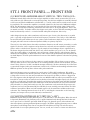
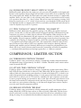
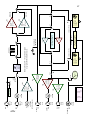
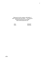
INTRODUCTION (see block diagram)
The STT-1 Origin is a collection of Millennia's essential product line combined into one box. You might
call it our "greatest hits" compilation. The STT-1 is a single channel (mono) processing chain with various
signal path topologies (vacuum tubes, discrete transistors, audio transformer, transformerless) all selectable at various functions. The STT-1 offers an entirely discrete, entirely Class-A direct signal path from
input to output. The signal path can be variously selected to use vacuum tubes or transistors, transformer
or non-transformer coupling. The STT-1 also offers additional monolithic utility outputs. There are (yes,
we counted) at least 134 different product combinations available in the STT-1 Origin — ranging from
the most musically transparent, sonically accurate, and dynamically stable audio circuits, to sublime levels
of vacuum tube and transformer 'euphony', and everything in between. The possibilities afforded the creative engineer, producer, and musician are virtually endless. The STT-1 includes the following functions,
employing the essential topology of Millennia products as noted by name:
1.) HV-3 discrete hybrid solid state microphone preamplifier -or2.) M-2 vacuum tube microphone preamplifier
3.) Vacuum tube instrument DI input, routable into M-2 vacuum tube -or- HV-3 solid state gain amplifiers
4.) Balanced line level (+4) input, routable into M-2 vacuum tube -or- HV-3 solid state gain amplifiers
5.) NSEQ four-band parametric EQ, selectable via vacuum tube -or- discrete solid state audio topology
6.) TCL opto-compressor/limiter/de-esser, selectable via vacuum tube, solid state, or non-amplifier topology
7.) All paths selectable via transformer -or- transparent transformerless input signal path
The STT-1 Origin has three available audio inputs.
1.) Line Input (XLR or 1/4" phone, rear panel)
2.) Mic Input (XLR, rear panel)
3.) Instrument DI Input (1/4" phone, front panel)
A user must select one of the above three inputs via the "SOURCE" rotary switch. The above inputs cannot be combined or mixed internally. Polarity of any input can be flipped 180 degrees, if desired. The mic
input can also receive +48V Phantom power, if required.
All input sources (mic, line, DI) are routed directly to the front-end gain amplifiers. A front-end gain amplifier is selectable as either vacuum tube (M-2) or solid state (HV-3). Each front-end gain amplifier has
its own gain adjustment potentiometer (approximately +10 dB to +50 dB solid state range and +20 dB
to +40 dB vacuum tube range). A user can select one front end gain amplifier, only (VT or SS) — front
end gain amplifiers cannot be mixed or used simultaneously. Additionally, a Millennia MIT-01 audio-path
transformer is selectable at all inputs (mic, line, DI) to the gain amplifiers. Use the transformer when you
want to add an enhanced, "in-your-face" euphonic personality to high-level input signals. The MIT-01
input transformer remains relatively uncolored and sonically neutral with nominal signal levels.
The front-end amplifiers feed two areas simultaneously: (1) a direct utility ouput and (2) the EQ/Dynamics section. The direct output is placed before the EQ and Dynamics sections. The direct output is
FET-based, monolithic, balanced, and always active. The EQ and Dynamics sections can share the same
amplifier stage (selectable as vacuum tubes or field effect transistors), which opens up some interesting
operational features. The ORIGIN's Opto-Dynamics functions can be used with vacuum tube amplfication, solid state amplification, or with no additional amplification whatsoever. See page 16 for important
detail on EQ and Dynamics co-operation.
The STT-1 has three other 'main' outputs: (1) monolithic XLR balanced, (2) discrete 100% Class-A 1/4"
unbal, and (3) discrete 100% Class-A XLR unbalanced. Main outputs sit at the back end of the STT-1,
following all functions. An additional RCA phono jack provides a linking function for stereo operation of
two STT-1 Dynamics sections. The large scale VU meter is a true audio responding level meter which can
be selected to measure the main output level or Dyanamics gain reduction.
STT-1
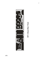
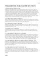
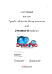
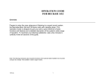
STT-1 REAR PANEL
(1) MICROPHONE INPUT "MIC INPUT"
Conventional 3-pin female XLR input jacks for use with all standard balanced microphones, both phantom and non-phantom powered. Provides +48 Volts DC Phantom powering via front panel switch. Input
impedance is approximately 6,200 ohms with phantom power switched in. Microphone input is selected
via a front panel rotary switch marked "Source - MIC." Pin 2 is positive polarity. Pin 3 is negative polarity.
Connector contacts are Neutrik Galvatronic gold plated. It is suggested that XLR cable connectors used
with the STT-1 employ identical plating. This input feeds either the vacuum tube gain amplifier (M2)
or solid state gain amplifier (HV-3), with or without transformer coupling, depending on the status of
front panel Twin Topology "TT" and "XFMR" switches. With non-transformer coupling, the maximum
microphone input levels are +3 dBu (vacuum tube) and +14 dBu (solid-state). For reference, a Neumann
U87Ai directly in front of a screaming vocalist (127 dB SPL) will output approximately -6 dBu. (NOTE:
Do not let the front panel "overload indicator" LED fool you. It begins to turn on with a mic preamp
output of +18 dBu. When you first see the red LED turn on dimly, you have 14 dB of output headroom
remaining.)
(2) LINE LEVEL INPUT "LINE INPUT"
Conventional 3-pin female XLR connector for use with balanced line level audio signals. A line level
signal is defined here as nominal +4 dBu operating level. Pin 1 is ground. Pin 2 is positive polarity. Pin
3 is negative polarity. A 1/4" phone jack is wired in parallel with the XLR (Tip=pin 2, Ring=pin 3,
Sleeve=pin 1). Input impedance is approximately 2,200 ohms (x2). Line level input is selected via a front
panel rotary switch marked "Source - LINE." This input feeds either the vacuum tube gain amplifier
(M-2) or solid state gain amplifier (HV-3), with or without transformer coupling, depending on the status
of front panel Twin Topology "TT" and "XFMR" switches. Minimum line input gain is achieved when
amplifier gain controls are set fully counter-clockwise. Maximum line level input level is +30 dBu into
the solid state gain amplifier and +19 dBu into the vacuum tube gain amplifier. Unbalanced "semi-pro"
(-10 dBv) signals should be tried in both the front panel DI input and the line level input — select the
input which sounds best. Line level input XLR connector contacts are Neutrik Galvatronic gold plated. It
is suggested that XLR cable connectors used with the STT-1 employ identical plating.
(3) FRONT END DIRECT OUTPUT "DIRECT OUT"
Conventional three pin male XLR connector providing balanced, line level output directly from the
front-end amplifiers (MIC, LINE, DI). This output is configured before the EQ, Compressor, De-esser,
and main outputs. This direct output is essentially equivalent to the output on an HV-3 micamp and
can be used in addition to the main outputs (below). Pin 1 is ground. Pin 2 is positive polarity. Pin 3 is
negative polarity. This line level output is capable of driving <600 ohm loads and long, high capacitance
cables. Outputs may be configured in an unbalanced configuration by grounding pin 3, or taking pin 2
directly as an unbalanced signal while floating pin 3. In the former configuration, the output is automatically increased by 6 dB. Connector contacts are Neutrik Galvatronic gold plated. It is suggested that XLR
cable connectors used with the STT-1 employ identical plating.
(4) MAIN OUTPUT #1 "MAIN OUT - BAL"
Conventional three pin male XLR connector providing balanced, line level output from all stages of the
STT-1. Can be used simultaneously with all other outputs. Pin 1 is ground. Pin 2 is positive polarity. Pin
3 is negative polarity. This monolithic-based, balanced line level output is capable of driving <600 ohm
loads and long, high capacitance cables and has a maximum output level of +32 dBu. Outputs may be
configured in an unbalanced pin-2-hot configuration by either grounding pin 3, or taking pin 2 directly
as an unbalanced signal while floating pin 3. In the latter configuration, the output is decreased by 6 dB
STT-1
115
STT-1 Origin Rear Panel
PUSH
STT-1
ORIGIN STT-1
PUSH
(5) MAIN OUTPUT #2 "MAIN OUT - UNBAL"
Conventional three pin male XLR connector providing unbalanced, line level output from all stages
of the STT-1. Can be used simultaneously with all other outputs. This XLR sits directly above the 1/4"
unbalanced output connector. Pin 1 is ground. Pin 2 is positive polarity. Pin 3 is ground. This output is
all discrete, pure Class-A, and is capable of driving < 600 ohm loads and long, high capacitance cables.
This output should drive a balanced destination with no interface concerns. In the rare instance where a
balanced destination exhibits difficulty with an unbalanced source, use the balanced output (#4 above).
Connector contacts are Neutrik Galvatronic gold plated. It is suggested that XLR cable connectors used
with the STT-1 employ identical plating.
(6) MAIN OUTPUT #3 "MAIN OUT - UNBAL"
Conventional 1/4" female phone connector providing unbalanced, line level output from all stages of the
STT-1. Can be used simultaneously with all other outputs. Tip is signal positive polarity, Sleeve is ground.
This output is all-discrete, pure Class-A and is capable of driving < 600 ohm loads and long, high capacitance cables. This output should drive a balanced destination with no interface concerns. In the rare instance where a balanced destination shows difficulty with an unbalanced source, use the balanced output
(#4 above). This output is paralleled with Output #5 (above).
(7) DYNAMICS LINK "Dyn Link"
Conventional RCA-style phono jack providing a connection to the dynamics side chain circuit. Use to
link dual STT-1 units for stereo operation. Any conventional RCA phono cable should work appropriately.
(8) EARTH/AUDIO GROUND JUMPER
A barrier terminal which ties earth ground to audio ground. If ground "hum" loops are experienced when
using the STT-1, removing this jumper may help. Using this jumper to lift ground, the integrity of the
chassis/earth ground connection is never compromised. Do not defeat the earth grounding pin on the AC
plug.
(9) AC VOLTAGE MAINS SELECTION "100-120" or "200-240"
A power entry module with a removable fuse holder block. This fuse holder block is selectable for 100
- 120 Volt or 200 - 240 Volt worldwide mains powering. The fuse block contains two fuses — one fuse is
in series with the hot power line while the other fuse is in series with the neutral power line. Both fuses
must be installed. To change the mains voltage selection, remove IEC power connector and assure that
the STT-1 is not connected to mains power. With a non-conductive tool, gently pry the fuse block away
from the power entry module. Remove the two fuses and replace both with type as shown below. Slide
out the internal PC Board, turn it over, and reinsert the PCB so that the desired AC mains voltage appears
in the viewing window. Double check that the fuses installed correspond to the AC mains voltage range
which appears in the viewing window. Gently push the fuse block back until flush and snug.
FUSES:
For 100-120 VAC mains, use two 5 x 20 mm, 1A, slow blow, 250 V, Littelfuse 218 or equiv.
For 200-240 VAC mains, use two 5 x 20 mm, 500 mA, slow blow, 250 V, Littelfuse 218 or equiv.
(10) POWER ENTRY "IEC Power Receptacle"
An IEC-type AC line-power receptacle for use with removable cords. Use only the power cord provided
STT-1
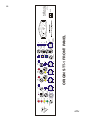
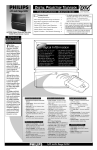
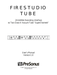
STT-1 FRONT PANEL — FRONT END
(1) FRONT-END AMPLIFIER SELECT SWITCH - TWIN TOPOLOGYtm
Pushbutton switch which selects the front-end gain amplifier as either entirely vacuum tube (VT) or entirely solid state (SS). When used as a microphone preamp, the solid state amplifier is essentially identical
to the front-end found on Millennia's acclaimed HV-3 — used by a who's who in critical acoustic recording worldwide. The vacuum tube amplifier is essentially identical to the front-end of Millennia's sublime
M-2b. The DI instrument input uses a tested and selected low noise, high voltage (300+ Volts) 12AT7
vacuum tube for impedance buffering, which then feeds either the VT or SS gain amplifiers. There's also
an unusual twist here. To further enhance the Origin's sonic palate, we have included something that Millennia has historically avoided — a switch selectable audio path transformer. Here's why...
Audio designers know that audio transformers add various types of sonic color (distortion) to an audio
path — especially at high dynamic levels and wide frequency excursions. This is why, to date, Millennia
has avoided audio path transformers. In our opinion, audio transformers simply have no place in a critical signal path when acoustic realism and dynamic stability are primary objectives.
That said, it is also widely known that audio transformer distortion can add "artistic personality" to audio
signals. For decades, creative engineers and producers have selected various transformer-coupled audio
paths to achieve a marked sonic signature. A good example is found in Rupert Neve's original Class-A,
all-discrete designs from the 1960s. Mr. Neve's early console modules (1272, 1073, etc.) are in demand
today due to their ability to "cut through" a mix and present a "bigger than life" sonic signature. Hugely
unnatural, and delightfully so! What causes these audio artifacts? It's predominantly the transformers. We
can thank Rupert's old audio path transformers for most of that familiar euphonic coloration and pleasing
distortion.
Millennia enjoys a fine collection of these 1960's era console modules. We use them on pop recording
dates (by choice, however, more than 90% of our recording schedule remains acoustic classical, jazz, and
ethno-eclectic; where we use HV-3 and M-2b micamps exclusively). We know intimately the "sound" that
a purposefully designed audio path transformer can deliver. It is with this understanding and mission that
Millennia presents our first product with an audio path transformer.
Numerous listening tests were performed on a wide range of off-the-shelf transformers. We couldn't
find a stock transformer that had the particular "sound" we were searching for. We then embarked upon
a design effort to create our own unique transformer. Developed for its ability to deliver a "bigger than
life" sonic signature when hit high input levels, the new Millennia MIT-01 audio input transformer is not
intended for acoustic reality nor musical accuracy. Rather, when used with higher input levels, the MIT01 offers a colorful sonic personality that engineers and producers of popular music will likely find both
highly artistic and eminently useful. This transformer can be switched in and out of the front-end audio
path; selectable via a front panel switch (see #4). The transformer can be used with all input types (microphones, line-level, and instrument-DI), but will likely be most sonically pronounced when used with
condensor microphones. When used with nominal input levels, the transformer exhibits modest sonic
coloration. The remaining functional areas of the STT-1, including the vacuum tube or solid state EQ,
dynamics, and output sections, remain inherently transformerless.
(2) PHANTOM POWER SELECT SWITCH ("+48V")
Pushbutton switch which provides phantom power (+48 Volts DC) to the microphone. When this switch
is depressed (illuminated red), phantom power is applied simultaneously through dual 6.81k ohm resistors to pins 2 and 3 of the three pin female XLR mic input. Use phantom power with condensor and
other microphones requiring traditional phantom supply. CAUTION: Applying phantom power to ribbon
microphones could damage them. Do not use phantom with ribbons, moving coil, and other microphones which do not require phantom power. Use care, as well, not to insert or extract mic cables from
STT-1
10
(3) POLARITY REVERSE SWITCH "POL REV"
A pushbutton switch which, when depressed and illuminated, reverses the polarity (180 degree inversion) of
all input signals, including the DI, mic input, and line input.
(4) TRANSFORMER SELECT SWITCH "XFMR IN"
A pushbutton switch which, when depressed and illuminated, places the Millennia MIT-01 audio path transformer in the front-end circuit. When used with high level signals, such as when using a pair of STT-1 units
for mixdown applications, the engineer may notice a marked 'enhancement' in sonic signature when the transformer is inserted. We have designed this transformer to provide a unique, "fat" sonic coloration with condensor microphones which gives the engineer a richer, fuller, 'bigger-than-life' image when used with aggressive
sources such as drums and electric bass. Read more about this transformer in section (1).
(5) OVERLOAD INDICATOR "OL"
A single red LED (light emitting diode) which begins turn-on (most dim) around +18 dBu and becomes
fully illuminated at +24 dBu at the direct output. The gradual illumination feature offers better indication of
approximate direct output level when compared with a typical "on/off" LED.
(6) VACUUM TUBE GAIN CONTROL "VACUUM TUBE GAIN"
A potentiometer which offers a front-end vacuum tube gain range of approximately 18 dB, being an absolute
gain range of approximately +22 dB to +40 dB at the direct output. When Line Input is used, it is recommended that this Gain Control remain fully CCW with the Output Master Level control set between 12
o'clock and 3 o'clock as a starting point. If less gain is required, lower the Master Level. If additional gain is required for line level signals (such as unbalanced "-10" signals), raise the level using use the Vacuum Tube Gain
Control. Line level signals sound fantastic in the Origin, but for optimized performance of EQ and Compressor
with line level sources, the stand-alone NSEQ-2 and TCL-2 Twincom stereo products offer slightly improved
specifications. This is due to the additional (and required) interface circuitry found in the Origin. NOTE: We
did not attempt to unify the rotational position or resolutions of the SS and VT gain controls. That is, the user
cannot place each gain potentiometer at the same angular setting and expect the same gain. Rather, we have
optimized each gain amplifier unto itself, not in relation to the other gain amplifier.
(7) SOLID STATE GAIN CONTROL "SOLID STATE GAIN"
A potentiometer which offers a front-end solid state gain range of 40 dB, being an absolute gain range of
approximately +10 dB to +50 dB at the direct balanced output. The Origin is optimized for mic-level and
instrument-level signals. When Line Input is used, it is recommended that this Gain Control remain fully
CCW with the Output Master Level control set between 10 o'clock and 2 o'clock as a starting point. If additional gain is required for line level signals, raise the level using use the Gain Control. Line level signals
sound fantastic in the Origin, but for optimized performance of EQ and Compressor with line level sources,
the stand-alone NSEQ-2 and TCL-2 Twincom stereo products offer slightly improved specifications. This is
due to the additional (and required) interface circuitry found in the Origin. NOTE: We did not attempt to
unify the rotational position or resolutions of the SS and VT gain controls. That is, the user cannot place each
gain potentiometer at the same angular setting and expect the same gain. Rather, we have optimized each gain
amplifier unto itself, not in relation to the other gain amplifier. NOTE: An approximate 20 dB of additional
solid state gain is available if necessary. Contact Millennia for customization information.
(8) SOURCE SELECT SWITCH "SOURCE: MIC - LINE - DI"
Rotary switch (Grayhill, military-spec, gold plated) which selects the front-end input source as either microphone, line level, or 1/4" DI (instrument, keyboard, etc.). Mic, Line, and DI inputs all feed the same front-end
amplifiers (selectable via switches as either vacuum tube or solid state, transformer-coupled or transformerless). When used as a solid state amplifier, the circuit is essentially identical to the front-end found on Millennia's acclaimed HV-3. When used as a vacuum tube amplifier, the circuit is essentially identical to Millennia's
sublime and musically euphonic M-2b front-end. The DI input offers a standard 1/4" phone jack exhibiting a
very high input impedance via a single 12AT7 vacuum tube circuit.
STT-1
11
PARAMETRIC EQUALIZER SECTION
(9) BAND IN/OUT SWITCH "IN"
Pushbutton switch which places its associated EQ band in circuit or out of circuit. There are
four bands of equalization on the STT-1 Origin. The four frequency bands are labeled LF (low
frequencies), LM (low-mid frequencies [20 Hz - 2.5 kHz]), HM (high-mid frequencies [250 Hz
- 25 kHz]), and HF (high frequencies). An EQ band is in circuit when its associated band switch
is depressed and LED is illuminated. Because of the equalizer's unique network-shunt design,
EQ bands should have no detectable sonic signature when they are in circuit as long as the
boost/cut control is set at zero. Band In/Out switches are provided both for comparing a single
EQ band setting versus flat-band response, and for bypassing the EQ entirely.
(10) FREQUENCY SELECT SWITCH
Rotary switch (Grayhill, gold contacts, military spec) which selects fixed high and low band frequencies. LF control center frequencies are set to 20, 34, 56, 100, 180, and 270 Hz. HF control
center frequencies are set to 4.8k, 5.8k, 8.0k, 10k, 16k, and 21 kHz.
(11) PEAK/SHELF SELECT SWITCH
Pushbutton switch which selects LF band and HF band curve shape. When switch is depressed
and LED is illuminated, EQ is shelving at 6 dB per octave. When switch is not depressed, EQ is
peaking with a fixed "Q" of 1.0.
(12) BOOST/CUT CONTROL
Conductive plastic rotary potentiometer offering up to +15 dB of boost and -15 dB of cut.
Boost/Cut potentiometer has 21 detented positions for accurate repeatability and session logging.
(13) PARAMETRIC FREQUENCY CONTROL
Conductive plastic rotary potentiometers (2) which sweep all center frequencies from 20 Hz to
25 kHz. The low-mid band ("LM") sweeps 20 Hz to 220 Hz -or- 200 Hz to 2.2 kHz, depending on the status of Frequency Range Switch (below). The high-mid band sweeps 250 Hz to 2.5
kHz -or- 2.5 kHz to 25 kHz, depending on the status of Frequency Range Switch (below). This
control is optionally available with 21-step detents for accurate repeatability and logging.
(14) PARAMETRIC FREQUENCY RANGE SELECT SWITCH "10X"
Pushbutton switch which selects 1X or 10X parametric frequency range. When switch is depressed and corresponding LED is illuminated, frequencies as shown on front panel legend are
multiplied by 10X. When switch is not depressed and LED is not illuminated, frequencies are as
shown on front panel legend.
(15) PARAMETRIC QUALITY CONTROL "Q"
Conductive plastic rotary potentiometer which sweeps "Q" (Quality factor) from 0.4 to 4.0.
"Q" is defined as the ratio of the center frequency to the bandwidth. For example, a filter boost
setting with "3 dB down points" near 100 Hz and 1000 Hz exhibits a "Q" of approximately 0.4.
This control is optionally available with 21-step detents for accurate repeatability and session
logging.
STT-1
T
IN
REV
IN
POL
O
XFMR
INST
LINE
MIC
IN
+48V
SOURCE
SS
IN
INPUT TT
VT
OUT
OL
50 dB
SOLID STATE GAIN
40 dB
VACUUM TUBE GAIN
UMEN
STR
T
IN
34
15
20
0
180 270
100
56
LF
15
IN
0
15
4.0
Q
0.4
15
X10
0.6
0
15
4.0
2.5k
Q
2.1k
1.0
300
250
IN
1.4k
1.6k
1.2k
HM
400
900
0.4
15
5.8k
4.8k
0.6
0
16k 21k
10k
8.0k
HF
15
IN
IN
SS
IN
OFF
DE-ESSER
4.9k
2.0
+20
RATIO
METER
GR
30:1
15:1
1.4:1
COMP
+LIM
OUTPUT
MUTE
20:1
9:1
3.0
100
-20
2:1
6:1
RELEASE
ATTACK
THRESH
3:1
4:1
0.02
IN
PRE
EQ
0.08
10.7k
8.2k
12.0k
6.8k
OUT
POST
EQ
FLIP DYNAMICS
VT
OUT
EQ/COMP TT
EQ
OUTPUT
MASTER
0 dB
METER
ZERO
IN
IN
IN
20
T
VU
+
5 32 1 0 1
2
10 7
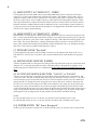
ORIGIN STT-1 FRONT PANEL
15
X10
220
190
1.0
25
20
IN
120
140
90
LM
30
50
3
POWER
ST T-1
Music & Media Systems
Millennia
12
PUT (HI-Z)
IN
STT-1
13
(16) EQUALIZER IN/OUT SELECT SWITCH "EQ IN"
Pushbutton switch which places the single (yes, only one) active EQ amplifier in the signal path.
Because of this equalizer's unique design, the four bands of active filters are not technically 'in' the
direct audio signal path. Rather, the filter bands exist within the shunt network of a single audio
amplifier. Hence, an active filter is only effecting audio when its associated Boost/Cut control
is in a position other than "0" — that is, when a Boost/Cut control is boosting or cutting. If all
Boost/Cut controls are set to "0" (12:00 o'clock position), even though the EQ IN switch and all
four EQ Band switches are engaged, there will be no noticeable sonic difference until a Boost/Cut
control is adjusted away from its "0" position.
(17) TWIN TOPOLOGYtm SELECT SWITCH "EQ/COMP TT"
Pushbutton switch which selects the amplifier topology to be used by the equalizer and compressor, vacuum tube or solid state. When switch is depressed and LED is illuminated, EQ and
compressor are routed via a 100% Class-A solid state FET amplifier. When switch is not depressed and LED is not illuminated, EQ and compressor are routed via a 100% Class-A vacuum
tube amplifier. EQ and compressor amplifier path topologies cannot be selected separately. Not
a gimmick, Twin Topology is designed around two world class, musically optimized amplifiers
— one amplifier is based upon twin triode 300+ Volt vacuum tubes, while the other is based
upon all discrete Class-A biased J-FET servo amplifiers. Like having two distinctly different
equalizer path amplifiers and two distinctly different opto-compressor path amplifiers in one
chassis. We do not "match" inherent gains between the vacuum tube and solid state amplifiers
— a small gain differential between topologies (generally 1 or 2 dB) is not unusual.
COMPRESSOR / LIMITER SECTION
(18) THRESHOLD CONTROL "THRESH"
Conductive plastic rotary potentiometer offering a continuously variable compression threshold adjustment range of approximately -20 dBu to +20 dBu. Threshold is most sensitive when
control is turned fully CW.
(19) ATTACK TIME CONTROL "ATTACK"
Conductive plastic rotary potentiometer offering a continuously variable attack timing. When
fully CCW, the fastest attack time is achieved (2 mS). When fully CW, the slowest attack time is
achieved (100 mS). Opto-resistive gain reduction, as found in the Origin STT-1, is ideal for virtually all program material, including tracking of vocals, guitars, keyboards, and most acoustic
music. Moreover, when a pair of STT-1 units are combined, the opto-compressor can be used
for stereo program mixing, post production, and so forth. Opto-electronic gain reduction is not
the fastest known method of compression attack, but based on many years of listening experience with every gain reduction technology, we feel that well designed opto-resistive compression is the most sonically transparent method.
(20) RELEASE CONTROL "RELEASE"
Conductive plastic rotary potentiometer offering continuously variable compression release
timing. When fully CCW, the fastest release is achieved (20 mS). When fully CW, the slowest
release is achieved (3 seconds). Note that release times below 80 mS are normally used only
during de-essing. It is recommended that broadband compression use >80 mS release times.
STT-1
14
(21) RATIO CONTROL "RATIO"
Conductive plastic rotary potentiometer offering continuously variable compression ratio.
When fully CCW, the lowest and most gentle compression ratio is achieved (1.4:1). When fully
CW, the highest and most pronounced compression ratio is achieved (30:1). A compression
ratio of approximately 10:1 or higher is typically called "limiting" hence the STT-1 dynamics
section is properly called a "compressor/limiter."
(22) PRE / POST DYNAMICS SELECT SWITCH "FLIP DYNAMICS"
Pushbutton switch which determines the order in which the dynamics section is placed in the
audio signal path. When switch is depressed and LED is illuminated, the dynamics section
precedes the EQ section. When switch is not depressed, the dynamics section follows the EQ
section. Use this switch to achieve desired sonic objectives. In some cases, compressing equalized program can offer an "effect" not achievable with pre-EQ compression. When the Equalizer
is not enabled (EQ IN switch is disabled), pre/post selection is also disabled.
(23) DE-ESSER SELECT ROTARY SWITCH "DE-ESSER"
Rotary switch which selects the notching frequency of an opto-electronic de-esser. De-esser
provides selective filtering of particularly "sibilant" frequencies, such as found on overly breathy
singers, RF "hissing" artifacts encountered with certain wireless mic receivers during dropout,
and so forth. Compressor/limiter "dynamics" switch (#24) must be active to achieve de-essing
function.
Origin's de-essing function employs the same opto-resistive gain reduction elements used by
the broadband compressor/limiter. The de-essing function can be used simultaneously with the
parametric equalizer (pre or post), and can be used with the additional solid-state audio path
amplifier, vacuum tube audio path amplifier, or with no additional amplifier in the audio path.
The de-esser and broadband compressor/limiter cannot be used simultaneously.
When the “Comp/Lim In” switch (#24) is active and illuminated, and the de-essing rotary
switch is fully counter-clockwise, the broadband compressor/limiter is active and the de-essing
function is off. As the de-essing switch is rotated clockwise, the broadband compressor/limiter
is disabled and the de-esser becomes active at the center frequency noted on switch. When any
de-essing frequency is selected, the meter Gain Reduction function is disabled.
The de-esser works in conjunction with the compressor/limiter’s dynamics controls (threshold,
attack, release, ratio) and signal input level. At lower input, threshold, and ratio levels, the deessing function is less prominent. At higher levels, de-essing becomes more pronounced. The
de-esser in the Origin is intended for modest de-essing duties. For more aggressive sibilance, a
dedicated de-essing unit with greater flexibility is suggested.
At low settings (fully CCW) of threshold and ratio, the de-esser function is essentially off. For
instance, at 1.4:1 ratio, the de-essing notch is very broad with minimal cut. As the ratio and
threshold controls are increased clockwise, the de-essing notch becomes more pronounced
with an apparent tighter “Q”. It is recommended that the fastest attack and release be used as a
starting point; the user should then experiment with different settings of attack and release to
achieve optimal de-essing performance. The Origin de-esser has also been found effective on RF
microphone "envelope hiss," guitar fret squeek noise, and such.
STT-1
15
(24) DYNAMICS IN/OUT SWITCH "COMP + LIM IN"
Pushbutton switch which places an opto-compressor/limiter into the signal path. When switch is
depressed and LED is illuminated, opto-electronic gain reduction elements are activated. When
pushbutton switch is not depressed, gain reduction is not in circuit. Opto-compressor/limiter can
be used with or without additional active amplifier stage (vacuum tube or solid-state).
(25) MUTE SELECT SWITCH "OUTPUT MUTE"
Pushbutton switch which mutes all main outputs, balanced and unbalanced. When switch is depressed and LED is illuminated, audio signal is muted at the main outputs. Does not effect Direct Output from the front end amplifiers. When switch is not depressed, muting is not active.
(26) VU METER FUNCTION SELECT SWITCH "METER GR"
Pushbutton switch which determines the VU meter function. When switch is depressed and
LED is illuminated, VU meter indicates the amount of dynamics gain reduction. When switch is
not depressed, VU meter indicates the actual output level of the balanced main outputs. A meter
reading of 0 VU is equivalent to a balanced output of +4 dBu. NOTE: Unbalanced main output
is 6 dB lower output than shown on VU meter. Gain reduction metering is disabled when de-esser is enabled.
(27) MASTER LEVEL CONTROL "OUTPUT MASTER"
Master output level control. Fully CCW is fully off. Fully CW offers an additional 10 dB of gain
relative to the front-end amplifier circuits. Unity output level is achieved when this control is
approimately 2:00 o'clock (at the tip of the right "bat wing"). At 10:00 o'clock, output level is
attenuated approximately -16 dB.
(28) VU METER ADJUSTMENT "METER ZERO"
Inset multi-turn trimmer potentiometer which adjusts the VU meter zero point when meter is
set to Gain Reduction. Use insulated "wand" tool designed for trimpot adjustment. Allow ample
time (1/2 hour recommended) for the STT-1 Origin circuits and chassis to 'warm up' and reach
a stable operating temperature before attempting to set the GR zero point of VU meter.
(29) VU METER
True analog-level meter providing indication of output level or gain reduction. Meter is backlit.
Meter backlighting also serves as operational 'pilot' light.
(30) POWER SWITCH "POWER"
Rocker switch for switching AC line power on and off.
(31) TEMPLATE
(not shown) A logging template for use with the STT-1 Origin is available for download on the
Millennia web site at: http://www.mil-media.com/origin.html
STT-1
16
COMPRESSOR T/T OPERATION
Please review the STT-1 block diagram. You'll note that the opto-compressor gain reduction
"shunt" elements, both pre-EQ and post-EQ, are passive. This means that no additional audio
path amplifiers are required for dynamics control, though an additional 10 dB of "make up
gain" can be achieved via the master output buffer amplifiers if required. In some cases, the
sound of an additional Class-A biased amplifier in the dynamics signal path may be preferred.
As such, the STT-1 ORIGIN opto-compressor can be selected to use three different signal paths,
follows:
1.) With vacuum tube signal path amplifier, or
2.) With solid-state signal path amplifier
The opto-compressor and parametric equalizer can share the same Class-A signal path amplifier
(selectable as vacuum tube or solid-state). To use the compressor with the additional signal path
amplifier, assure that the "EQ IN" switch is depressed and illuminated. If no EQ is desired (compressor only), assure that all four "EQ Band" switches are disabled — this will effectively remove all EQ function while allowing the dynamics processing to traverse an additional vacuum
tube or solid state amplifier signal path. In practice, this additional amplifier would usually be
selected as a vacuum tube path for heightened sonic coloration.
3.) Without any additional signal path amplifier
The opto-compressor function is passive, meaning that no additional signal path amplifiers
are required for dynamics operation. Passive opto-resistive elements are oriented as "variable
resistors" to ground, achieving broad levels of gain reduction. To use passive opto-compression,
whether pre-EQ or post-EQ, simply assure that the "EQ IN" switch is not depressed.
We feel this unique design approach offers maximum flexibility in achieving the widest range of
dynamics sonic possibilities, from straight-wire 'minimalist' design to variously applied Class-A
amplification paths. Note that EQ and compressor control switches give visual indication of the
functions described above.
SUMMARY
The STT-1 ORIGIN could very quickly become among the only front-end analog paths you'll
ever need. With over 130 different product and topology combinations in one 2U rack chassis,
and the inherent range of sonic possibilities, the STT-1 is designed for the producer/engineer/
musician who doesn't have large amounts of time to spend patching and repatching racks of
analog front-end gear trying to achieve "that sound." Now, in one chassis, it's possible to easily
and quickly patch vacuum tube equipment with discrete solid state Class-A equipment, transformer-coupling and non-transformer coupling, various inputs and outputs, even dispensing
with certain signal path amplifiers altogether if not desired. It's —all— here in one compact
chassis. The STT-1 vastly expands the range of every artist's sonic pallette at a price/performance level previously unknown in professional audio. STT-1 — Straight to Tape. Or for those
no longer using tape, Straight to Track!
STT-1
1/4“
PHONE
XLR
LINK
DYNAMICS
OUT
BAL
OUT
UNBAL
OUT
PHONO
RCA
XLR
MALE
+25V
-25V
+48V
+350V
+5V
+12V
+18V
-18V
AMPLIFIER
SOLID-STATE
AMPLIFIER
SOLID-STATE
DISCRETE
MUTE
VU METER
LEVEL/GR
AMPLIFIER
SOLID-STATE
MONOLITHIC
50V
FSA-01
350V
50V
MONOLITHIC
50V
INTERNAL DC POWER
PHONE
XLR
2
1/4“
MALE
2
XLR
MALE
2
JACK (front panel)
INPUT
SELECT
(ROTARY)
PHANTOM
AMPLIFIER
TUBE
VACUUM
12AT7
+48V Phantom
FEMALE
2
XLR
FEMALE
2
1/4“ PHONE
IN
DI
DIRECT
STT-1
IN
LINE
IN
MIC
XFMR
FSA-1
DISCRETE
POST-EQ
SHUNT CELL
DYNAMICS CONTROLS
PRE-EQ
SHUNT CELL
REDUCTION
DYNAMICS PRE EQ
T/T
AMPLIFIER
TUBE
VACUUM
M-2B
350V
OPTO-GAIN
COMPRESSOR / LIMITER
COMPRESSOR IN/OUT
AMPLIFIER
SOLID-STATE
50V
EQUALIZER CONTROLS
FOUR-BAND PARAMETRIC
T/T
REDUCTION
DYNAMICS POST EQ
T/T
TUBE
VACUUM
AMPLIFIER
350V
INDICATOR
OVERLOAD
XFMR
AMPLIFIER
STATE
HV-3 SOLID
36V
OPTO-GAIN
EQ IN
Copyright 2000 Millennia Media, Inc.
Millennia Media STT-1 “Origin” Block Diagram
(PASSIVE)
REVERSE
POLARITY
Audio Transformer
Millennia MIT-01
EQ IN
MAX:+40 dB
MIN: +20 dB
MAX:+50 dB
MIN: +10 dB
T/T
17
18
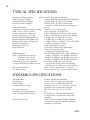
TYPICAL SPECIFICATIONS
Instrument DI Input Amplifier
Selected 12AT7 dual triode vacuum tube
Solid State Input Amplifier
Discrete NPN Transistor Hybrid (HV-3 PAM-01)
Vacuum Tube Input Amplifier
Selected 12AX7 & 12AU7 vacuum tubes
EQ and Dynamics Amplifiers
Selected 12AX7 & 12AU7 vacuum tubes
— or FSA-01 J-FET all-discrete semiconductors
Total Vacuum Tubes
Five (5)
Total Discrete Transistors (FET & NPN)
Twenty five (25) in audio path
THD + Noise, 20 Hz - 30 kHz
.005% typical SS, .05% typical VT
Frequency Response -3 dB points
3 Hz to 200 kHz, typical. Varies with topology
Frequency Response, +/- 0.5 dB
10 Hz to 100 kHz typical. Varies with topology
Maximum Balanced Mic Input Level +14 dBu (SS), +3 dBu (VT), non-xfmr
Maximum Balanced Line Input Level
+30 dBu (SS), +19 dBu (VT), non-xfmr
Maximum Mic Input to Transformer
+1 dBu @ 30 Hz, +20 dBu @ 1 kHz (3% THD)
Maximum Output Level
+32 dBu, main balanced output
Maximum System Gain
60 dB, main balanced output.
Input Impedance
6,200 ohms, nominal, microphone input
2,200 (x2) ohms, line input
> 1 megohm, instrument DI input
Output Impedance 24.3 (x2) ohms balanced. 49.9 ohms unbalanced
Noise (Common source, mic in)
-71 dB @ 50 dB gain (-121 dB EIN), solid state
(30 ohm source, mic in)
-68 dB @ 50 dB gain (-118 dB EIN), solid state
(150 ohm source, mic in)
-66 dB @ 50 dB gain (-116 dB EIN), solid state
Noise (Line in, EQ in, dynamics in)
better than -90 dB, varies with topology
Common Mode Rejection Ratio, mic in
> 50 dB, 100 mV CM, varies with topology
> 80 dB typical @ 60 Hz. varies with topology
Three-pin XLR Polarity Pin 2 = positive polarity, Pin 1 = ground
1/4" Phone Polarity
Sleeve = ground, Tip = positive polarity unbal
DYNAMICS SPECIFICATIONS
Threshold Range
Attack Range
Release Range
Compression Ratio Range
De-essing Frequencies
Dynamics pre/post EQ selection?
Twin Topology Selection (EQ In)
EQ Select Switch Out
40 dBu, Continuously Adjustable
2 mS to 100 mS, Continuously Adjustable
20 mS to 3.0 S, Continuously Adjustable
minimum 1.4:1 (6:1 at 12 o'clock pot setting)
maximum 30:1 Continuously Adjustable
Off, 4.9k, 6.8k, 8.2k, 10.7k, 12.0 kHz
Yes
TT Switch In = FET Signal Path Amplifier
TT Switch Out = Vacuum Tube Signal Path Amplifier
"Passive" Opto-Compression Shunt Network
(see instructions pg 16 for details on EQ and Dynamics co-operation)
STT-1
19
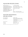
EQUALIZER SPECIFICATIONS
Maximum Boost & Cut
Parametric "Q" Adjustment Range
Low-Mid (LM) Parametric Sweep Freqs
High-Mid (HM) Parametric Sweep Freqs
Low (LF) Range Fixed Frequencies High (HF) Range Fixed Frequencies Low/High Range Fixed "Q"
Parametric Frequency Multiplier (10X?)
Peak/Shelf Selection on Hi & Lo bands?
Bypass Selection on Each Band?
Twin Topology Selection
+/- 15 dB (21 step detent)
Q = 0.4 to 4.0, sweepable
20 Hz to 220 Hz -or- 200 Hz to 2.2 kHz
250 Hz to 2.5 kHz -or- 2.5 kHz to 25 kHz
20, 34, 56, 100, 180, 270 Hz
4.8, 5.8, 8.0, 10, 16, 21 kHz
Q = 1.0
Yes
Yes
Yes
Switch In = FET Signal Path Amplifier
Switch Out = Vacuum Tube Signal Path Amplifier
ELECTRO-MECHANICAL
SPECIFICATIONS
Power Consumption
Power Requirements Fuses (2 required)
Internal DC Power
Dimensions
Net Weight
50 Watts, nominal
100VAC to 240VAC, 50/60Hz, selectable
2 ea 1A with 100-120VAC mains (5x20mm, slow-blow, 250V)
2 ea 500mA with 200-240V mains (5x20mm,
slow-blow, 250V)
+350V, +50V, +25V, -25V, +18V,
-18V, +12V, +5V
19" W x 15.5" D x 3.5" H
approximately 25 pounds
Millennia Media reserves the right to change specifications, delivery, and pricing without notice.
STT-1
20
WARRANTY
Millennia Media will repair this product, free of charge, in the USA, in the event of defect of
materials or workmanship for one (1) year following date of purchase. This warranty is extended only to the original purchaser. This limited warranty covers failures due only to defects
in materials and workmanship which occur during normal, intended use and does not cover
damage which occurs in shipment or failures which are caused by products not supplied by Millennia Media. This limited warranty does not cover failures which arise from accident, misuse,
abuse, neglect, mishandling, misapplication, faulty installation, improper adjustment, alteration
or modification of product, incompatibilities, line-power surges, acts of God, or service performed by anyone other than Millennia Media or its authorized agent. Vacuum tube failures are
not covered under warranty.
LIMITS AND EXCLUSIONS
There are no express warranties except as listed above. Millennia Media shall not be liable for
special, subsequent, incidental, consequential, or punitive damages, including, but not limited
to: damage to recordings, broadcasts, microphones, mixing consoles, or any associated equipment, downtime costs, loss of goodwill, or claims of any party dealing with purchaser for such
damages resulting from the use of this product. All warranties, express and implied, including
the warranties of merchantability and fitness for a particular purpose are limited to the applicable warranty period set forth above.
Some states do not allow the exclusion or limitation of incidental or consequential damages, or
length of time an implied warranty remains in effect. As such, the above exclusions may not apply. This warranty gives you specific legal rights and you may also have other rights which can
vary from state to state.
MILLENNIA MUSIC & MEDIA SYSTEMS
Millennia Media, Inc.
4200 Day Spring Court
Placerville, CA 95667-9500
T 530-647-0750
F 530-647-9921
[email protected]
http://www.mil-media.com
The STT-1 Origin is hand-crafted in USA
Manual printed in USA
STT-1