1
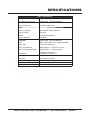
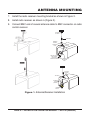
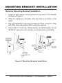
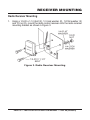
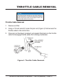
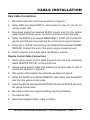
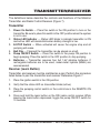
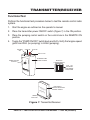
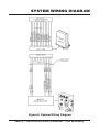
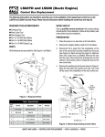
INSTALLATION/OPERATION MANUAL MIRATRON WIRELESS REMOTE CONTROL RADIO MAYCO MODEL C30HDZ Revision #0 (09/09/09) THIS MANUAL MUST ACCOMPANY THE EQUIPMENT AT ALL TIMES. TABLE OF CONTENTS Warranty ......................................... 3 Overview ........................................ 4 Specifications ................................ 5 Care And Handling ......................... 6 Parts ............................................... 7 Antenna Mounting .......................... 7-8 Mounting Bracket Installation ....... 9 Receiver Mounting ......................... 10 Throttle Cable Removal ................. 11 Control Box Removal ..................... 12 Cable Installation .......................... 13 Wiring Diagram............................... 14 Transmitter/Receiver ..................... 15-16 Troubleshooting ............................. 17 System Wiring Diagram ................. 18 PAGE 2 — INSTALLATION OPERATION MANUAL — REV. #0 (09/09/09) WARRANTY LIMITED ONE YEAR WARRANTY Miratron Incorporated, hearafter referred to as Miratron, is providing this warranty in lieu of all other express or implied warranties, including any warranty of merchantability or fitness for a particular purpose. This warranty is buyer’s exclusive remedy for all claims against Miratron. Miratron shall not be liable for any consequential or incidental damages. Miratron’s total liability for all contracts, negligence, or other claims shall be limited to the price paid for its product. Miratron promises buyer that any Miratron product purchased by buyer shall be free from all material defects in desgin, material, or manufacturing for a period of one year from the manufacture date; provided, however, that the warranty shall not extend to ordinary wear and tear or to normally replaceable components (e.g., batteries). During the warranty period, Miratron may repair or replace (in its sole discretion) any product suffering from a warranty defect and returned freight prepaid by buyer, with no charge to buyer for any warranty repair or replacement. The warranty shall remain in full force and effect for such 1 year period, provided that the product: (1) was installed, operated, and maintained properly; (2) has not been abused or misused; and (3) has not been repaired, altered, or modified outside of Miratron’s authorized facilities. This warranty provides specific legal rights that may be varied by state law. Miratron products are not designed for life or safety applications. Product specification subject to change without notice. NOTICE System must be physically disconnected from the machine prior to welding on the machine. Welding may cause permanent damage to sensitive electronic components, and will void this warranty. INSTALLATION/OPERATION MANUAL — REV. #0 (09/09/09) — PAGE 3 OVERVIEW ALWAYS read manual before attempting to operate the equipment. Failure not to read manual could cause severe equipment damage and or damage to the receiver and transmitter. Make sure work area is safe to operate radio control receiver and transmitter. This device complies with Part 15 of the FCC rules. Operation is subject to the following two conditions: (1) This device may not cause harmful interference, and (2) This device must accept any interference received, including interference that may cause undesired operation. If any problems or malfunctions occur using this product, discontinue use immediately, and refer to the Troubleshooting Guide in this manual. If the problem persists, call your equipment dealer immediately for parts and or service. NOTICE Disconnect and lock-out all power sources before making any wiring connections to the receiver. NOTICE Improper operation of the transmitter receiver could cause damage to the equipment. DO NOT allow unauthorized personnel to operate this equipment before reading manual. NOTICE MIRATRON, Inc. transmitters and receivers are not intended for life or safety applications, MIRATRON, Inc. shall not accept resposibility for installation, application, or safety of machine or systems which utilize MIRATRON, Inc. transmitters and receivers. PAGE 4 — INSTALLATION OPERATION MANUAL — REV. #0 (09/09/09) SPECIFICATIONS Table 1. Specifications Miratron Model Number: RX4 Radio Control Receiver General: CMD16-0138 ~ (MQ P/N EM98216) Power Requirements Radio: 12-24VDC, 500mA max Frequency Standard 902-928 MHz, FHSS, ISM Band Frequecy Control Direct FM FCC ID OUR9XCITE (Standard) Receiver Sensitivity -106 dBM Transmitter: Range CMD16-0138 ~ (MQ P/N EM98216) 300 ft. (91.44 meters) Line of Sight (Standard) Battery Type 1.5 Volt “AA” Alkaline (4) Battery Life (Standard) Standby, 80 hrs. — Transmitt, 12-16 hrs. Battery Life (Extended Range) Standby, 40 hrs. — Transmitt, 6-8 hrs. LED Indicator Flashing = Battery Good Double Blink = Battery Low Enclosure: Transmitter Environmental: Operating Storage High Impact Polystyrene -14° F ~ 158° F (-10°C ~ 70° C) -40° F ~ 185° F (-40°C ~ 85° C) INSTALLATION/OPERATION MANUAL — REV. #0 (09/09/09) — PAGE 5 CARE AND HANDLING Transmitter: Clean transmitter gently with a damp cloth. DO NOT immerse transmitter in water, or spray with hose. DO NOT store outside. DO NOT drop transmitter or otherwise subject transmitter to physical shock. DO NOT expose transmitter to extreme temperatures. DO NOT open transmitter enclosure. Transmitter contains no serviceable parts. Receiver: Remove receiver from machine prior to welding on machine DO NOT paint electrical connector. Use only factory provided antenna and cabling. DO NOT open receiver enclosure except to change radio channel or make adjustments to factory settings. Use transmitter to test functions. DO NOT apply voltage to circuit board directly. PAGE 6 — INSTALLATION OPERATION MANUAL — REV. #0 (09/09/09) PARTS/ANTENNA MOUNTING Parts: Make sure all parts are accounted for before performing the installation. The following parts are included with the kit: Radio Transmitter Radio Receiver Spiral Antenna with associated mounting hardware Coaxial Antenna Cable Data /Power Cable (5-wire) Remote Control Cable Receiver Mounting Bracket Battery Disconnection 1. Disconnect the negative terminal of the battery cable from the battery. Ant enna Mounting 1. Drill a 3/4” hole into the hood on the C30HDZ as shown in Figure 1. 2. After hole has been drilled, deburr hole opening. 3. Tilt the engine hood slightly forward to gain access to the antenna hole opening. Support the hood with a block of wood to maintain the desired access position. 4. Insert antenna cable thru 3/4” hole opening in hood. Insert BNC end of cable first. 5. With one hand holding the antenna end of the cable through the antenna hole opening, connect the locking flange, antenna and rubber gasket. Tighten locking flange securely. 6. Secure coaxial antenna with pressed on tie-wrap pads to interior of engine hood. INSTALLATION/OPERATION MANUAL — REV. #0 (09/09/09) — PAGE 7 ANTENNA MOUNTING 7. Install the radio receiver mounting bracket as shown in Figure 2. 8. Install radio receiver as shown in (Figure 3). 9. Connect BNC end of coaxial antenna cable to BNC connector on radio control receiver. STEP 3 LOCKING FLANGE ANTENNA RUBBER GASKET COAXIAL CABLE ANTENNA END RX4 RADIO RECE CONT IVER ROL MIRA TRO N SEE RECEIVER MOUNTING BRACKET A INSTRUCTIONS BNC CONNECTOR RECEIVER END STEP 4 LOCKING FLANGE TIGHTEN TIE-WRAP PADS (INSIDE) RX4 RADIO RECE CONT IVER ROL MIRA TRO N DATA CABLE Figure 1. Antenna/Receiver Installation PAGE 8 — INSTALLATION OPERATION MANUAL — REV. #0 (09/09/09) MOUNTING BRACKET INSTALLATION Receiver Mounting Bracket Installation 1. Install the radio receiver mounting bracket to the frame of the C30HDZ as shown in Figure 2. 2. Using the bracket as a template, mark the holes to be drilled on the frame. 3. Drill two 3/8-diameter holes into the frame as shown in Figure 2. After both holes have been drilled, deburr each hole opening. 4. Using a 3/8 X 1-1/2 bolt (2), 3/8 lock washer (2), 3/8 flat washer (2) and 3/8 nut (2), secure the radio receiver mounting bracket to the frame. Figure 2. Mounting Bracket Installation INSTALLATION/OPERATION MANUAL — REV. #0 (09/09/09) — PAGE 9 RECEIVER MOUNTING Radio Receiver Mounting 1. Using a 1/4-20 x 1-1/4 bolt (2), 1/4 lock washer (2), 1/4 flat washer (2) and 1/4 nut (2), mount the radio control receiver onto the radio receiver mounting bracket as shown in Figure 3. Figure 3. Radio Receiver Mounting PAGE 10 — INSTALLATION OPERATION MANUAL — REV. #0 (09/09/09) THROTTLE CABLE REMOVAL NOTICE The removal of the control box may not be required. If wiring connections, crimping and splicing can be made without removing the box, then disregard control box/ throttle cable removal instructions. Throttle Cable Removal 1. Remove air filter. 2. Using a 7/8-inch wrench loosen the jam nut (Figure 4) that secures the throttle cable to the control box. 3. Once jam nut has been loosened, pull upward then back on the throttle cable to disengage throttle cable from locking mechanism. Figure 4. Throttle Cable Removal INSTALLATION/OPERATION MANUAL — REV. #0 (09/09/09) — PAGE 11 CONTROL BOX REMOVAL Control Box Removal 1. Using a 10 mm wrench, remove the upper bolt (Figure 5) that secures the control box bracket to the engine. 2. Using a 13 mm wrench, remove the lower bolt that secures the control box to the engine V-belt cover. 3. Position control box so that wire side is facing upwards. Figure 5. Control Box Removal PAGE 12 — INSTALLATION OPERATION MANUAL — REV. #0 (09/09/09) CABLE INSTALLATION Data Cable Connections 1. Wire data cable into control box as shown in Figure 6. 2. Splice RED wire labeled BATT+. and connect to relay K1, pin 30 (12 volt key switch ON). 3. Disconnect engine fuel solenoid BLACK ground wire from the control panel support bracket. Leave 1.5-inches of wire on control box side. 4. Splice the WHITE wire labeled EMERGENCY STOP with the BLACK ground wire that was removed from the control panel support bracket. 5. Crimp a #16-14 (5/16”) terminal ring onto the BLACK wire labeled FRAME GROUND. Connect this end of the wire to engine chassis ground. 6. Insert connector end of data cable into Miratron receiver. Remote Control Cable Connections 1. Insert yellow remote control cable (Figure 6) into the 2-pin receptacle labled REMOTE OUTLET on the control box. 2. Secure yellow remote cable with pressed on tie-wrap pads to side of control box as shown in Figure 6. 3. Wire remote control cable to the control box as shown in Figure 6. 4. Splice the WHITE wire labeled REMOTE (data cable) with the BLACK wire from the yellow remote cable 5. Splice the WHITE wire labeled NO PUMP ON with the WHITE wire from the yellow remote cable. 6. Re-install control box using the existing mounting hardware. 7. Re-install air filter 8. Reconnect negative battery cable to battery. INSTALLATION/OPERATION MANUAL — REV. #0 (09/09/09) — PAGE 13 WIRING DIAGRAM 12-PIN DATA CABLE L RO NT CO IO ER AD EIV 4 R EC RX R MIR R AT ON 5-WIRES FRAME GROUND (BLACK) REMOTE (WHITE) ADD TERMINAL RING BLACK BATT + (RED) WHITE YELLOW REMOTE CABLE SPLICE DEUTZ ENGINE CONNECTOR NO PUMP ON (WHITE) E-STOP (WHITE) IGNITION SWITCH SPLICE SPLICE BLACK 3 HOUR METER 1 RED WIRE (ADD) +12VDC IGNITION ON PIN 30 RELAY K1 1 2 PRESSED-ON TIE-WRAPS CONNECT YELLOW REMOTE CABLE TO RECEPTACLE LABELED “REMOTE OUTLET” 3 NOTE: PUMPING CONTROL SWITCH OIL PRESSURE 1 BATT LEAVE 1.5 INCHES OF WIRE EXPOSED ON CONTROL BOX SIDE. OIL TEMPERATURE Figure 6. Wiring Diagram PAGE 14 — INSTALLATION OPERATION MANUAL — REV. #0 (09/09/09) TRANSMITTER/RECEIVER The definitions below describe the controls and functions of the Miratron Transmitter and Radio Control Receiver (Figure 7). Transmitter 1. Power On Switch — Place this switch in the ON position to turn on the transmitter. Be sure to place this switch in the OFF position when the system is not in use. 2. Status LED Indicator — Status LED blinks to indicate transmitter is ON and active. LED will double-blink when battery strength is low. 3. E-STOP Switch — When activated will cause the engine stop and all pumping will cease. 4. Belt Clip — If desired the transmitter can be placed on a belt. 5. Pump ON/OFF Switch — Place this switch in the pump ON position to begin pumping. Place the switch in the OFF position to stop pumping. 6. Batteries — Transmitter requires four AA 1.5V alkaline batteries. If rechargable batteries are to be used, nickel-metal hydride (NiMH) are recommended. Receiver (Learn Button) Transmitter and receiver must be matched as a pair. Perform the procedure listed below to pair the transmitter and receiver. Reference Figure 7. 1. Place the ignition switch in the ON position. 2. Verify that the status LED on transmitter blinks (active). 3. Place the pumping control switch on the control box in the REMOTE ON position. 4. Press and hold the learn button on the RX4 radio control receiver. While keeping the learn button depressed, toggle the pump ON/OFF switch for 10 seconds. INSTALLATION/OPERATION MANUAL — REV. #0 (09/09/09) — PAGE 15 TRANSMITTER/RECEIVER Functional Test Perform the functional test procedure below to test the remote control radio system. 1. Start the engine as outlined on the operator’s manual. 2. Place the transmitter power ON/OFF switch (Figure 7) in the ON position. 3. Place the pumping control switch on the control box in the REMOTE ON position. 4. Toggle the “PUMP ON/OFF” switch back and forth. Verify that engine speed goes from IDLE (no pumping) to HIGH (pumping). POWER ON STATUS E-STOP BELT CLIP PUMP ON/OFF SWITCH PUM P ON TRANSMITTER MODEL CDM16 BATTERY COMPARTMENT + OFF RX 4R AD RE IO C CE O IV NTR ER O MI RA TR ON L + 1.5V 1.5V 1.5V 1.5V A L K A L I N E A L K A L I N E A L K A L I N E A L K A L I N E 4 AA 1.5V ALKALINE BATTERIES REQUIRED RX4 RADIO CONTROL RECEIVER MODEL CDM16 LEARN BUTTON Figure 7. Transmitter/Receiver PAGE 16 — INSTALLATION OPERATION MANUAL — REV. #0 (09/09/09) TROUBLESHOOTING Symptom Transmitter does not function at all Table 2. Troubleshooting Possible Problem LED status indicator not flashing. Solution Turn transmitter power switch ON. Weak dead battery, replace batteries. Check orientation of batteries. LED indicator not lit when power ON/OFF switch is pressed. Make sure transmitter has be matched (paired) to receiver. Receiver is not powered up. Transmitter range is poor LED indicator not lit when power ON/OFF switch is pressed Weak dead battery, replace batteries. LED indicator lit when switch is pressed Check receiver antenna Maintain line-of-sight Avoid obstructions Check for interference Heavy rain reduces range Transmitter works (RX LED Check wiring. in receiver comes on) but outputs do not operate Make sure output wires are not shorted to Ground Verify load is wired correctly. INSTALLATION/OPERATION MANUAL — REV. #0 (09/09/09) — PAGE 17 SYSTEM WIRING DIAGRAM Figure 8. System Wiring Diagram PAGE 18 — INSTALLATION OPERATION MANUAL — REV. #0 (09/09/09) NOTE PAGE INSTALLATION/OPERATION MANUAL — REV. #0 (09/09/09) — PAGE 19 INSTALLATION/OPERATION MANUAL HERE’S HOW TO GET HELP PLEASE HAVE THE MODEL AND SERIAL NUMBER ON-HAND WHEN CALLING UNITED STATES Multiquip Corporate Office 18910 Wilmington Ave. Carson, CA 90746 Contact: [email protected] MQ Parts Department Tel. (800) 421-1244 Fax (800) 537-3927 800-427-1244 310-537-3700 Fax: 800-672-7877 Fax: 310-637-3284 800-421-1244, Ext. 279 310-537-3700, Ext. 279 Mayco Parts Fax: 800-672-7877 Fax: 310-637-3284 Warranty Department 800-306-2926 310-537-3700 Service Department Fax: 310-537-1173 Technical Assistance 800-421-1244 310-537-3700 Fax: 310-537-4259 MEXICO 800-478-1244 Fax: 310-631-5032 UNITED KINGDOM MQ Cipsa Multiquip (UK) Limited Head Office Carr. Fed. Mexico-Puebla KM 126.5 Momoxpan, Cholula, Puebla 72760 Mexico Contact: [email protected] Tel: (52) 222-225-9900 Fax: (52) 222-285-0420 Hanover Mill, Fitzroy Street, Ashton-under-Lyne, Lancashire OL7 0TL Contact: [email protected] Tel: 0161 339 2223 Fax: 0161 339 3226 CANADA Multiquip 4110 Industriel Boul. Laval, Quebec, Canada H7L 6V3 Contact: [email protected] Tel: (450) 625-2244 Tel: (877) 963-4411 Fax: (450) 625-8664 © COPYRIGHT 2009, MULTIQUIP INC. Multiquip Inc, the MQ logo and the Mayco logo are registered trademarks of Multiquip Inc. and may not be used, reproduced, or altered without written permission. All other trademarks are the property of their respective owners and used with permission. This manual MUST accompany the equipment at all times. This manual is considered a permanent part of the equipment and should remain with the unit if resold. The information and specifications included in this publication were in effect at the time of approval for printing. Illustrations, descriptions, references and technical data contained in this manual are for guidance only and may not be considered as binding. Multiquip Inc. reserves the right to discontinue or change specifications, design or the information published in this publication at any time without notice and without incurring any obligations. Your Local Dealer is: