1
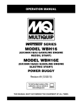
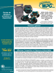
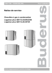
LS60TD and LS600 (Deutz Engine) Control Box Replacement The following instructions are intended to assist the user in the installation of the replacement control box on the LS60TD and LS600 Concrete Pump. Please read all instructions before installing the control box and relay kit. Required tools/components Work safely! Only a qualified service technician with proper training should perform this installation. Follow all shop safety rules when performing this installation. Crimping Tool Wire Cutter Tool Wire Stripper Tool Two 12-10 AWG Butt Splice One 14-16 AWG Butt Splice One 12-10 AWG Spade Lug Preparation 1. Place the pump in an area free of dirt and debris. 2. Disconnect negative battery cable from the battery. Parts Verify that parts are accounted for. See Figure 1 and Table 1. 2 5 3. Disconnect the 4 plugs from the receptacles on the rear of the control box currently installed on the pump (see Figure 2). Mark and tag the plugs for reference when new control box is installed. Remove the fuse from the rear of the control box and keep the nut and washers. They will be used to reinstall the fuse on the new control box. 4. Remove the existing control box as shown in Figure 2. Keep the hex bolts, flat washers and lock nuts. They will be used in the installation of the new control box. 3 4 OPEN HATCH PLUGS (4) FUSE OLD CONTROL PANEL 1 Figure 1. Required Parts FLAT WASHER (8) Table 1. Required Parts Item No. Part No. Description QTY. 1 EM517648A Digital Control Box 1 2 EM515799 Relay Kit 1 3 ___ 10/32" Hex Nut 1 Not Provided 4 ___ #10 Lock Washer 1 Not Provided 5 ___ #10 Flat Washer 1 Not Provided Remarks HEX BOLT (4) LOCK NUT (4) SCREW (2) Figure 2. Removing Existing Control Box LS60TD and LS600 — CONTROL bOX replacement — Rev. #1 (03/23/12) — Page 1 INSTALLATION connections 1. Install the replacement digital control box on the pump using the existing hardware. See Figure 3. Refer to Figure 5 for connections from the relay to the plugs . CONTROL BOX REAR VIEW HARNESS LOCK WASHER 1. Connect #86 purple 12 AWG wire from Relay K1 to terminal #6 on Plug P1 using a spade connector. RELAY 2. Connect #85 black wire from Relay K1 to starter ground point using a butt splice. STUD 3. Connect #87 purple 10 AWG wire from Relay K1 to terminal #4 on Plug P1 using a butt splice. FLAT WASHER 4. Cut wire from terminal #4 on Plug P4 flush to the plug. Terminal will not be used. 5. Connect #30 red wire from Relay K1 to the other end of the cut wire using a butt splice. 6. Reconnect the 4 plugs to the corresponding receptacles on the new control box. See Figure 4 for location of receptacles. Receptacle J5 will not be used. HEX NUT HATCH NOTICE Use extreme care when connecting the control box rear receptacle plugs to make sure that correct orientation is followed. PLUGS HEX BOLT (4) Relay Fuse J5 (Not Used) Receptacles FLAT WASHER (8) LOCK NUT (4) SCREW (2) NEW CONTROL PANEL Figure 3. Replacement Digital Box Installation 2. Attach the relay kit to the digital control box by securing it to the stud shown in Figure 3, using the appropriate hardware (user provided). J1 J2 J3 J4 Figure 4. Control Box Rear Receptacles 7. Install the fuse to the rear of the new control box. 8. After all connections are made, reconnect the battery. Turn the control panel ignition switch to the ON position. The control box panel should light. You will see and hear the engine fuel solenoid energize. 9. Perform control box programming instructions. LS60TD and LS600 — CONTROL bOX replacement — Rev. #1 (03/23/12) — Page 2 BLACK 16 AWG 86 30 87 Butt Splice Relay K1 85 REAR VIEW Relay Connector PURPLE 10 AWG STARTER GROUND POINT PURPLE 12 AWG IN + 12V DC Power Butt Splice ORANGE 10 AWG OUT Existing Fuse RED 10 AWG 4 6 Spade Lug P1 Cut Flush P4 Plugs Butt Splice 4 TO START/STOP SOLENOID Figure 5. Connections Between Control Box and Relay LS60TD and LS600 — CONTROL bOX replacement — Rev. #1 (03/23/12) — Page 3 Plug P1 Outside Terminal # 6 (Ignition B+) 12 AWG Purple Wire Plug P1 Outside Terminal # 4 Splice B+ Power (Fuse) 10 AWG Purple Wire #86 #87 #85 #30 16 AWG Black Wire Starter Ground Point 10 AWG Red Wire Plug P4 Terminal # 4 (Cut Wire Flush) Opposite End to Deutz Start/Stop Solenoid Figure 6. Relay P/N EM515799 Relay Schematic Diagram LS60TD and LS600 — CONTROL bOX replacement — Rev. #1 (03/23/12) — Page 4 CONTROL BOX PROGRAMMING 6. Once the language is selected, place the CONTROL switch to the center off position. NOTICE Control boxes come pre-programmed from the factory and configured to Model LS300. It is necessary to reprogram the model configuration to match your unit. Machine Model Configuration 1. Turn the IGNITION switch to the ON position. Do not start engine. See Figure 7 to identify control box switches. 2. Place the FLOW DIRECTION switch to reverse. Digital Screen Ignition Switch Reset Switch 7. Turn the IGNITION switch to OFF then ON again to memorize final configuration. 3. Place the AUTOMATIC/JOG switch to jog. 4. Place the CONTROL switch to remote. RESET SCROLL SET OFF VOLUME DECREASE FLOW DIRECTION FORWARD ON INCREASE REVERSE IGNITION CONTROL START LOCAL CENTER OFF JOG JOG “A” JOG “B” MULTIQUIP INC. CARSON, CALIFORNIA 90746 USA 310-537-3700 800-421-1244 WWW.MULTIQUIP.COM Automatic/Jog Switch 6. Once the model is selected, place the CONTROL switch to the center off position. 7. Turn the IGNITION switch to OFF then ON again to memorize final configuration. CYLINDER STROKE AUTOMATIC 5. Manually hold the CYLINDER STROKE switch to the jog B position. While holding the switch to the jog B position, toggle the RESET switch down 5 times. After the fifth time, move the CYLINDER STROKE switch to the jog A position. While holding the switch to the jog A position, toggle the RESET switch down to the desired model (LS60TD or LS600). REMOTE Control Switch Cylinder Stroke Switch Flow Direction Switch Figure 7. Control Box Switches Language Selection 1. Turn the IGNITION switch to the ON position. Do not start engine. 2. Place the FLOW DIRECTION switch to reverse. 3. Place the AUTOMATIC/JOG switch to jog. 4. Place the CONTROL switch to remote. 5. Manually hold the CYLINDER STROKE switch to the jog B position. While holding the switch to the jog B position, toggle the RESET switch down 5 times. On the fifth time, the digital screen will display the current set language. Toggle RESET switch again to change language, if desired. LS60TD and LS600 — CONTROL bOX replacement — Rev. #1 (03/23/12) — Page 5 CONTROL PANEL COMPONENTS 5 3 1 4 12 E 12 SCROLL 50 75 GENCY ST O ER M P RESET 1000 0 20 0 500 1500 SET 11 VOLUME ON 00 OFF START INCREASE DECREASE 2 ACCUMULATOR PRESSURE 13 IGNITION FLOW DIRECTION 7 12 50 75 1000 0 FORWARD CONTROL 500 1500 8 CENTER OFF CYLINDER STROKE 20 00 0 REMOTE LOCAL REVERSE JOG AUTOMATIC JOG “B” JOG “A” PUMPING PRESSURE REMOTE 9 10 6 Figure 8. Digital Control Panel Components 1. Emergency Stop Button — Press emergency stop button to stop pump in an emergency. Turn knob counterclockwise to disengage the stop button. 2. Ignition Switch — Insert the ignition key here to start the engine. Turn the key clockwise to the ON position, then continue turning clockwise to the START position and release. To stop the engine turn the key fully counterclockwise to the STOP position. 3. Digital Readout Screen — Displays and monitors the various functions of the machine. 4. Scroll Switch — Allows the operator to scroll the various readout screens. 5. Reset Switch — Allows the operator to reset the stroke counter. 6. Remote Cable Connector — Insert the remote control input cable into this connector. 7. Direction Control Switch — This 2-position switch controls the direction of flow for any mix in the pump. The leftmost position sets the pumping direction to forward and the rightmost position sets the pumping direction to reverse. 8. Pumping Control Switch — This 3-position switch controls the pumping of the pump. The rightmost position (REMOTE) is for use with the remote control unit, the leftmost position (LOCAL) is for normal pumping operation, and the centermost position (CENTER OFF) prevents pumping. 9. Cylinder Stroke Control Switch — This 2-position switch controls the pumping function. The leftmost position (AUTOMATIC) sets the pump to automatic cycling. Set the switch to this position for normal pump operation. The rightmost position (JOG) changes the pump from automatic to manual cycling. This allows the cylinders to be manually cycled using the Manual Cylinder Jogging Switch. 10. Manual Cylinder Jogging Switch — This 2-position switch allows the operator to manually jog the cylinders to assist in clearing material line packs and is used to test pumping pressure. The leftmost position jogs Cylinder “A” and the rightmost position jogs Cylinder “B”. 11. Stroke Volume Control Switch — Increases or decreases the number of strokes per minute of the pump (not used on model LS60TD). 12. Accumulator Pressure Gauge — This gauge monitors the internal pressure of the Accumulator tank. Normal internal pressure should read approximately 1750 PSI during pumping. 13. Main Pressure Gauge — This gauge monitors the system pressure while pumping material. The maximum pressure rating is 4400 PSI ± 50. LS60TD and LS600 — CONTROL bOX replacement — Rev. #1 (03/23/12) — Page 6 DIGITAL READOUT SCREENS Screen 5 Primary Screen Displays the ON/OFF electrical signal status of the various 12 volt solenoids (Swing A circuit, Main A circuit, Main B circuit). Screen 1 Indicates the various modes of the switch settings. INDICATES SWING A CIRCUIT IS OFF 5 SWING A OFF Monitors engine RPM - Idle speed 900, High speed 2550. Battery charge indicator - Normal charge 13+ volts. Indicates electrical malfunction. INDICATES MAIN B CIRCUIT IS OFF MAIN A OFF MAIN B OFF INDICATES MAIN A CIRCUIT IS OFF Screen 6 Displays the ON/OFF electrical signal status for the Proximity Switch A, Proximity Switch B, Engine Fuel Solenoid, and Unloader Solenoid. INDICATES PROXIMITY A CIRCUIT IS OFF Secondary Screens Screen 2 (not used on Model LS60TD) Displays the position of the VOLUME CONTROL switch by indicating whether the increase or decrease position is on or off. INDICATES VOLUME SWITCH IS NOT IN THE - POSITION INDICATES UNLOADER CIRCUIT IS OFF FLOW DEC OFF 2 FLOW INC ON Screen 7 INDICATES THROTTLE IS ON Screen 3 Displays the number of hours the engine and pump have been used and the number of faults the pump has registered. All three indicators can be reset to zero by the RESET switch on the control panel. E HRS: 00000.0 3 PMP HRS: 00000.0 FAULTS: 00000000 RESET TO CLEAR MESSAGE OR INSTRUCTION INDICATES NO. OF HOURS PUMP HAS BEEN USED INDICATES THE NO. OF YARDS PER HOUR THROTTLE ON 7 STROKES: 20 STROKES/MIN 8.2 YDS/HR 10.7 INDICATES THE NUMBER OF STROKES INDICATES THE NO. OF STROKES PER MINUTE Screen 8 Displays the electrical status of the engine fuel solenoid. To test the 12-Volt solenoid status, activate with the RESET switch on the control panel. INSTRUCTION OR MESSAGE 8 INDICATES NO. OF FAULTS DETECTED Screen 4 Displays the number of strokes the main hydraulic cylinders have gone through. This indicator can be reset to zero by the RESET switch on the control panel. INDICATES A RUNNING COUNT OF NO. OF STROKES INDICATES FUEL SOLENOID CIRCUIT IS OFF Displays the number of times the main hydraulic cylinders stroke and the yards per hour output. This indicator can be reset to zero by the RESET switch on the control panel. INDICATES VOLUME SWITCH IS IN THE + POSITION INDICATES NO. OF HOURS ENGINE HAS BEEN USED 6 PROX A OFF PROX B ON FUEL SOL OFF UNLOADER OFF INDICATES PROXIMITY B CIRCUIT IS ON TO TEST FUEL SOL PRESS RESET FUEL SOL OFF INDICATES THE FUEL SOLENOID IS OFF Screen 9 Displays the communication status of the (optional) radio remote control. To activate a new remote control connection, use the reset switch on the control panel. 4 STROKE CTR: 0000 PRESS RESET TO ZERO STROKE CTR MESSAGE OR INFORMATION RADIO ADDRESS 9 COMMUNICATING PRESS RESET TO LEARN A NEW ONE IINSTRUCTION OR MESSAGE LS60TD and LS600 — CONTROL bOX replacement — Rev. #1 (03/23/12) — Page 7 INDICATES THAT RADIO REMOTE IS ON LS60TD and LS600 Control Box Replacement HERE’S HOW TO GET HELP PLEASEHAVETHEMODELANDSERIAL NUMBERON-HAND WHENCALLING United StateS Multiquip Corporate Office 18910 Wilmington Ave. Carson, CA 90746 Contact: [email protected] MQ Parts Department Tel. (800) 421-1244 Fax (800) 537-3927 Service Department 800-421-1244 310-537-3700 800-427-1244 310-537-3700 Fax: 800-672-7877 Fax: 310-637-3284 Warranty Department Fax: 310-537-4259 800-421-1244 310-537-3700 Fax: 310-943-2249 Technical Assistance 800-478-1244 Fax: 310-943-2238 mexico United Kingdom MQ Cipsa Multiquip (UK) Limited Head Office Carr. Fed. Mexico-Puebla KM 126.5 Momoxpan, Cholula, Puebla 72760 Mexico Contact: [email protected] Tel: (52) 222-225-9900 Fax: (52) 222-285-0420 Unit 2, Northpoint Industrial Estate, Globe Lane, Dukinfield, Cheshire SK16 4UJ Contact: [email protected] Tel: 0161 339 2223 Fax: 0161 339 3226 Canada Multiquip 4110 Industriel Boul. Laval, Quebec, Canada H7L 6V3 Contact: [email protected] Tel: (450) 625-2244 Tel: (877) 963-4411 Fax: (450) 625-8664 © COPYRIGHT 2012, MULTIQUIP INC. Multiquip Inc and the MQ logo are registered trademarks of Multiquip Inc. and may not be used, reproduced, or altered without written permission. All other trademarks are the property of their respective owners and used with permission. The information and specifications included in this publication were in effect at the time of approval for printing. Illustrations, descriptions, references and technical data contained in this document are for guidance only and may not be considered as binding. Multiquip Inc. reserves the right to discontinue or change specifications, design or the information published in this publication at any time without notice and without incurring any obligations. YourLocalDealeris: