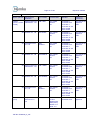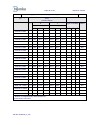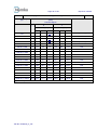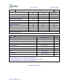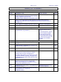
1
Test Report issued under the responsibility of www.nemko.com TEST REPORT IEC 60335-2-40 Safety of household and similar electrical appliances Part 2-40: Particular requirements for electrical heat pumps, air conditioners and dehumidifiers Report Reference No. ...................... : 255837 Date of issue....................................... : 2014-03-19 Total number of pages ........................ 100 pages CB/CCA Testing Laboratory Name : Nemko AS Address............................................... : Gaustadalléen 30, NO - 0373 Oslo, Norway Applicant's name.............................. : Samsung Electronics Co., Ltd. Address............................................... : Digital Air-solutions Business Team, 129, Samsung-ro, Yeongtong-gu, Suwon-si, Gyeonggi-do, 443-742 Korea, Republic of Phone: (+47) 22 96 03 30 Test specification: Standard ............................................. : IEC 60335-2-40:2002 (4. Edition) + A1:2005 (incl. Corr.1:2006) + A2:2005 with IEC 60335-1:2001 (4. Edition) (incl. Corr.1:2002) + A1:2004 (incl. Corr.1:2005) + A2:2006 (incl. Corr.1:2006) IEC 62233:2005 (1. Edition) Test procedure ................................... : CB Non-standard test method…………..: N/A Test Report Form No. ...................... : IEC60335_2_40F Test Report Form(s) Originator......................... : VDE Testing and Certification Institute Master TRF ....................................................... : Dated 2009-11 Copyright © 2009 IEC System for Conformity Testing and Certification of Electrical Equipment (IECEE), Geneva, Switzerland. All rights reserved. This publication may be reproduced in whole or in part for non-commercial purposes as long as the IECEE is acknowledged as copyright owner and source of the material. IECEE takes no responsibility for and will not assume liability for damages resulting from the reader's interpretation of the reproduced material due to its placement and context. If this Test Report Form is used by non-IECEE members, the IECEE/IEC logo and the reference to the CB Scheme procedure shall be removed. This report is not valid as a CB Test Report unless signed by an approved CB Testing Laboratory and appended to a CB Test Certificate issued by an NCB in accordance with IECEE 02. This Test Report, when bearing the Nemko name and logo is only valid when issued by a Nemko laboratory, or by a laboratory having special agreement with Nemko. Page 2 of 100 Test item description ....................... : Report No. 255837 Air-conditioner Trade Mark ......................................... : Manufacturer ...................................... : Same as applicant. Samsung Electronics Co., Ltd. Digital Air-solutions Business Team, 129, Samsung-ro, Yeongtong-gu, Suwon-si, Gyeonggi-do, 443-742 Korea, Republic of Model/Type reference ........................ : (Indoor unit) a) AM056FNLDEH; b) AM045FNLDEH; c) AM036FNLDCH; d) AM028FNLDCH; e) AM022FNLDCH Ratings................................................ : a) 0.53 A 95 W 220 – 240 V~ 50 Hz b) 0.52 A 90 W 220 – 240 V~ 50 Hz c) 0.35 A 75 W 208 – 230 V~ 60 Hz d) 0.34 A 60 W 208 – 230 V~ 60 Hz e) 0.32 A 47 W 208 – 230 V~ 60 Hz Additional information......................... : Cl. I, Built-in duct type (Slim duct – 1), Climate class T1 or T3, Indoor unit only. Optional accessory product; - Drain pump: model, MDP-E075SEE3D TRF No. IEC60335_2_40F Page 3 of 100 Report No. 255837 Testing procedure and testing location: CB/CCA Testing Laboratory: N/A Testing location/ address ........................ : Associated CB Laboratory: N/A Testing location/ address ........................ : Tested by (name + signature) .......: Approved by (+ signature) .............: Testing procedure: TMP Tested by (name + signature) .......: Jae Hyeon, Kim Approved by (+ signature) ..............: Jae Hong, Park Testing location/ address ........................ : Samsung Electronics Co., Ltd. Digital Air-solutions Business Team, 129, Samsung-ro, Yeongtong-gu, Suwon-si, Gyeonggi-do, 443-742 Korea, Republic of Testing procedure: WMT N/A Tested by (name + signature) .......: Witnessed by (+ signature) ............: Approved by (+ signature) .............: Testing location/ address ........................ : Testing procedure: SMT N/A Tested by (name + signature) .......: Approved by (+ signature) ..............: Supervised by (+ signature) ..........: Testing location/ address ........................ : Testing procedure: RMT Tested by (name + signature) .......: Approved by (+ signature) ..............: Supervised by (+ signature) ..........: Testing location/ address ........................ : TRF No. IEC60335_2_40F N/A Page 4 of 100 Report No. 255837 Summary of testing: Tests performed (name of test and test clause): - Clause 7: Marking and instructions - Clause 8: Protection against access to live parts - Clause10: Power input and current - Clause 11: Heating - Clause 13: Leakage current and electric strength at operating temperature - Clause 15: Moisture resistance - Clause 16: Leakage current and electric strength - Clause 19: Abnormal operation - Clause 20: Stability and mechanical hazards - Clause 21: Mechanical strength - Clause 22: Construction - Clause 23: Internal wiring - Clause 24: Components - Clause 25: Supply connection and external flexible cord - Clause 26: Terminals for external conductors - Clause 27: Provision for earthing - Clause 28: Screws and connections - Clause 29: Clearances, creepage distances and solid insulation - Clause 30: Resistance to heat and fire - Clause 31: Resistance to rusting - Annex E: Needle flame test - Annex N: Proof tracking test - Annex EE: Pressure test Testing location: Samsung Electronics Co., Ltd. Digital Air-solutions Business Team, 129, Samsung-ro, Yeongtong-gu, Suwon-si, Gyeonggi-do, 443-742 Korea, Republic of 1. Safety test conditions; Normal temperature condition was considered as following based on ISO 13253 and ISO 15042; - For climatic class T1, an appliance was installed with the indoor side subjected to 27°C and the outdoor side subjected to 35°C for cooling function. - For climatic class T3, an appliance was installed with the indoor side subjected to 29°C and the outdoor side subjected to 46°C for cooling function. - An appliance was installed with the indoor side subjected to 20°C and the outdoor side subjected to 7°C for heating function. 2. EMF test conditions; 1) Measuring distance (r1): 30 cm 2) Sensor locations: Around 3) Operating conditions: Continuously. Cooling mode: Lowest cooling, Heating mode: Highest heating 3. In this test report, the model AM056FNLDEH (indoor unit, built-in slim duct type) was mainly tested and evaluated as a representative by connecting it with the model AM080FXVAGR (outdoor unit) in combination with the model AM071FNLDEH (indoor unit, built-in slim duct type), AM071FN2DEH (indoor unit, built-in 2-way cassette type), AM056FNJDEH (indoor unit, named as a console type) and AM071FNCDEH (indoor unit, named as a ceiling type) under the most severe operating condition specified by the manufacturer. 4. For the relevant tests, a motor-compressor was equipped with an outdoor unit, which was approved by NEMKO employing a non-flammable refrigerant of R410A. TRF No. IEC60335_2_40F Page 5 of 100 Report No. 255837 Summary of testing: 5. This test report replaces the previous test report no. 241841 by following; - Revision on the critical component list. Refer to the Table 24.1 in main test report. 6. Heat exchanger of this appliance was tested and evaluated with the refrigerant R410A only in this test report. 7. The appliance shall be provided with a certified supply cord and interconnection cords complying with the national regulations of the countries in which the appliance is to be sold. The supply cord and interconnection cords were evaluated just for the reference in this test report. 8. Information about other standards/ documents considered; 1) ISO 5149 (1993, edition:1); Mechanical refrigerating systems used for cooling and heating – Safety requirements 2) ISO 13253 (2011, edition:2); Ducted air-conditioners and air-to-air heat pumps -- Testing and rating for performance 3) ISO 15042 (2011, edition:1); Multiple split-system air-conditioners and air-to-air heat pumps -- Testing and rating for performance Summary of compliance with National Differences: 1) All CENELEC members as listed in the following standards; EN 60335-2-40:2003 +A11:2004 +A12: 2005 +A1:2006 +A2:2009 EN 60335-1:2002 +A11:2004 +A1:2004 +A12:2006 +A2:2006 +A13:2008 +A14:2010 +A15:2011 EN 62233:2008 2) All CB members as listed in the IECEE Online Bulletin. All National differences listed in the CB Bulletin are covered by the National Differences and Group Differences for Europe (Common Modifications, Special National Conditions). 3) The product fulfils the requirements of the following standards; IEC 60335-2-40: 2002 (Fourth edition) +A1:2005 +A2:2005 IEC 60335-1:2001 (Fourth ed.) (incl. Corr.1:2002) +A1:2004 +A2:2006 (incl. Corr. 1:2006) EN 60335-2-40:2003 +A11:2004 +A12: 2005 +A1:2006 +A2:2009 EN 60335-1:2002 +A11:2004 +A1:2004 +A12:2006 +A2:2006 +A13:2008 +A14:2010 +A15:2011 EN 62233:2008 TRF No. IEC60335_2_40F Page 6 of 100 Report No. 255837 Copy of marking plate: 1 / 4 Model: AM056FNLDEH (Indoor unit) The artwork below may be only a draft. The use of certification marks on a product must be authorized by the respective NCBs that own these marks. TRF No. IEC60335_2_40F Page 7 of 100 Report No. 255837 Copy of marking plate: 2 / 4 Model: AM045FNLDEH (Indoor unit) The artwork below may be only a draft. The use of certification marks on a product must be authorized by the respective NCBs that own these marks. TRF No. IEC60335_2_40F Page 8 of 100 Report No. 255837 Copy of marking plate: 3 / 4 Model: AM036FNLDCH (Indoor unit) The artwork below may be only a draft. The use of certification marks on a product must be authorized by the respective NCBs that own these marks. - TRF No. IEC60335_2_40F Page 9 of 100 Report No. 255837 Copy of marking plate: 4 / 4 Model: AM028FNLDCH/ AM022FNLDCH (Indoor unit) The artwork below may be only a draft. The use of certification marks on a product must be authorized by the respective NCBs that own these marks. TRF No. IEC60335_2_40F Page 10 of 100 Report No. 255837 Name and address of production-sites (Factories): Factories are introduced as following; No. Address Factory 1: SUZHOU SAMSUNG ELECTRONICS CO., LTD. 501, Suhong East Road, Suzhou City, Jiangsu, 215021 China Factory 2: SUZHOU SAMSUNG ELECTRONICS CO., LTD. 218 Jiepu Road, Industry Park, Suzhou City, Jiangsu, China Factory 3: SAMSUNG ELECTRONICS CO., LTD. 107, Hanamsandan 6beon-ro, Gwangsan-gu, Gwangju-si, 506-723, Korea, Republic of Factory 4: THAI SAMSUNG ELECTRONICS CO., LTD. 313 Moo 1 Sukhaphiban 8 Rd., Sriracha Industry Park, T.Bung, A.Sriracha Chonburi, 20230 Thailand Factory 5: HANCHANG CO., LTD. 22, Sinwon-ro, Yeongtong-gu, Suwon-si, Gyeonggi-do, Korea, Republic of List of attachments: 1. Attachment 1 (13 pages): Attachment report to the IEC 60335-2-40 for European Group Differences and National Differences; Attachment Form No. ............ : EU_GD_IEC60335_2_40F Attachment Originator ............ : VDE Master Attachment................. : 2009-11 2. Attachment 2 (14 pages) Attachment report to the IEC 60335-1 for European Group Differences and National differences; Attachment Form No. ............ : EU_GD_IEC60335_1S Attachment Originator ............ : Nemko Master Attachment................. : 2011-12 3. Attachment 3 (4 pages): National Difference of Australia (AU) in the IECEE Online Bulletin. (http://www.iecee.org) No. IEC standard National standard reference 1 IEC 60335-1 (Fourth edition); am1; am2 AS/NZS 60335.1: 2002 Last modification: 2010-04-19 2 IEC 60335-2-40 (Fourth edition); am1; am2 AS/NZS 60335.2.40: 2006 No national deviation for Australia (AU). 4. Attachment 4 (4 pages): Schematic wiring/ Circuit diagram. 5. Attachment 5 (7 pages): Photos of appliance. TRF No. IEC60335_2_40F Page 11 of 100 Report No. 255837 Test item particulars .................................................. : Air-conditioner Classification of installation and use............................ : Fixed / Stationary appliance / Built-in duct type Supply Connection ....................................................... : Type Y attachment ...................................................................................... : ...................................................................................... : Possible test case verdicts: - test case does not apply to the test object ................. : N/A - test object does meet the requirement ....................... : P (Pass) - test object does not meet the requirement................. : F (Fail) Testing .......................................................................... : Date of receipt of test item ............................................ : 2014-02-04 Date (s) of performance of tests ................................... : 2014-02-05 to 2014-03-15 General remarks: The test results presented in this report relate only to the object tested. This report shall not be reproduced, except in full, without the written approval of the Issuing testing laboratory. "(See Enclosure #)" refers to additional information appended to the report. "(See appended table)" refers to a table appended to the report. Throughout this report a comma is used as the decimal separator. General product information: 1) This test report is for the models of indoor unit as following; a) AM056FNLDEH; b) AM045FNLDEH; c) AM036FNLDCH; d) AM028FNLDCH; e) AM022FNLDCH 2) The variant models, AM045FNLDEH; AM036FNLDCH; AM028FNLDCH; AM022FNLDCH are same as the model AM056FNLDEH just except for the electrical rating by the difference of outdoor unit which is connected with indoor unit. 3) Each model has different rated cooling/ heating capacity for the outdoor unit which is combined with the indoor unit. 4) This appliance is not considered having any IP degrees, i.e. IPX0. 5) This appliance is not intended to be installed where accessible to the general public, which is intended to be maintained by qualified service personnel and located at a level not less than 2,5m. 6) This test report is just for the indoor unit, and the indoor unit/ outdoor unit shall be installed by a service agent or similarly qualified persons with an end user’s preference with the combination specified by manufacturer. TRF No. IEC60335_2_40F Page 12 of 100 Report No. 255837 IEC 60335-2-40 Clause Requirement – Test 5 GENERAL CONDITIONS FOR THE TESTS 5.2 Result Verdict — Tests performed according to cl. 5, e.g. nature of supply, sequence of testing, etc. All the tests are conducted according to this standard. If the test of annex D has to be carried out, an additional appliance may be used (IEC 60335-1/A1) Not applicable. Tests of clause 21 carried out on separate samples. Tests of clauses 11, 19 and 21 require pressure measurements made at various points in refrigerating system (IEC 60335-2-40/A1) Performed according to the requirement. P N/A P At least one additional specially prepared sample required for tests of annex FF (Leak simulation tests) (IEC 60335-2-40/A1) P Temperatures on refrigerant piping measured during Tested as this clause. test of clause 11 (IEC 60335-2-40/A1) P 5.3 The tests of clause 14 and 21.2 and 22.24 are carried out after the tests of clause 29 (IEC 60335-1/A1) 5.6 Appropriate controls rendered inoperative during test Tested as this clause. (IEC 60335-2-40) P 5.7 Tests of clauses 10 and 11 carried out under most severe operating conditions within operating temperature range specified by manufacturer. Annex AA provide examples of such temperature conditions (IEC 60335-2-40) Annex AA: A7 A20. Also considered ISO 13253 and ISO 15042. P 5.10 For split-package units, refrigerant lines installed in accordance with installation instructions (IEC 60335-2-40) Provide with indoor unit and outdoor unit in separate. Installed as its instructions. P Not applicable. N/A Refrigerant line length is maximum length stated in installation instructions or (IEC 60335-2-40) 5.14 N/A 7,5 m, whichever is shorter (IEC 60335-2-40) 7,5 m P Thermal insulation of refrigerant lines applied in accordance with installation instructions (IEC 60335-2-40) Applied as instructions. P NOTE: Guidance is given in annex P for enhanced requirements that may be used to ensure an acceptable level of protection against electrical and thermal hazards for particular types of appliances used in an installation without a protective earthing conductor in countries that have warm damp equable climates (IEC 60335-1/A1) Not applicable. TRF No. IEC60335_2_40F N/A Page 13 of 100 Report No. 255837 IEC 60335-2-40 Clause Requirement – Test Result 5.101 Motor-compressor subjected to relevant test of clause 19 of IEC 60335-2-34, unless (IEC 60335-2-40) Not checked in the appliance. For the relevant tests of indoor unit, the outdoor unit was installed equipped with a motor-compressor which is approved by NEMKO employing a non-flammable refrigerant of R410A. motor-compressor comply with that standard (IEC 60335-2-40) Verdict N/A N/A 5.102 Motor-compressors tested and comply with IEC 60335-2-34 need not additionally tested for clause 21 (IEC 60335-2-40/A1) 6 CLASSIFICATION 6.1 Protection against electric shock: Class I, II, III (IEC 60335-2-40) 6.2 Protection against harmful ingress of water, IP degree in accordance with IEC 60529 (IEC 60335-2-40) Not checked in the appliance. N/A — Class I appliance. - appliances or parts intended for outdoor use be at least IPX4 (IEC 60335-2-40); Not checked in the appliance. - appliances intended only for indoor use (excluding laundry rooms) be IPX0 (IEC 60335-2-40); IPX0 for indoor unit. - appliances intended to be used in laundry rooms be at least IPX1 (IEC 60335-2-40). P — N/A P N/A 6.101 Degree of accessibility (accessible/not accessible to the general public) (IEC 60335-2-40) 7 MARKING AND INSTRUCTIONS 7.1 Rated voltage or voltage range (V)..........................: 220 – 240 V or 208 – 230 V See copy of marking plate. P Symbol for nature of supply including number of phases, unless for single phase operation (IEC 60335-2-40)......................................................: Provided with symbol (~) and frequency (50/60 Hz). P Rated frequency (Hz) ...............................................: 50/ 60 Hz P Rated power input (W) .............................................: Marked. P Rated current (A) ......................................................: Marked. P Manufacturer's or responsible vendor's name, trademark or identification mark ..............................: TRF No. IEC60335_2_40F Not intended to be installed where accessible to the general public. P — P Page 14 of 100 Report No. 255837 IEC 60335-2-40 Clause Requirement – Test Result Model or type reference ...........................................: (Indoor unit) a) AM056FNLDEH; b) AM045FNLDEH; c) AM036FNLDCH; d) AM028FNLDCH; e) AM022FNLDCH Symbol 5172 of IEC 60417, for class II appliances Class I appliance. Verdict P N/A Symbol IEC 60417-5036, for the enclosure of Not intended to be connected electrically-operated water valves in external to the water mains. hose-sets for connection of an appliance to the water mains (IEC 60335-1/A1) N/A Mass of refrigerant or of each refrigerant in blend (except for azeotropic type) (IEC 60335-2-40) ........: Not checked in the appliance N/A Refrigerant identification (IEC 60335-2-40) .............: Not checked in the appliance N/A Permissible excessive operating pressure for sanitary hot water heat pumps (IEC 60335-2-40) ...: Not such an appliance. N/A Maximum operating pressure for heat exchanger for hydronic fan coil/air handling units (IEC 60335-2-40/A2) ................................................: No hydronic unit. N/A Permissible excessive operating pressure of refrigerant circuit for suction and discharge, if they differ (IEC 60335-2-40) ............................................: Not marked with marking plate for indoor unit. N/A Symbol for degree of protection against ingress of water, other than IPX0 (IEC 60335-2-40) ................: IPX0 for indoor unit. N/A Separate marking of appliances with all rated characteristics of supplementary heaters (IEC 60335-2-40)......................................................: No supplementary haters. N/A Marking of direction of fluid flow (IEC 60335-2-40) It can be distinguished from the different diameter of pipes. N/A Flame symbol and instruction manual symbol of 7.6 visible when flammable refrigerant employed and following conditions exist (IEC 60335-2-40/A1): - accessing parts expected to be subjected to maintenance or repair (IEC 60335-2-40/A1); Intended for the use of a nonflammable refrigerant. — N/A - observing appliance under sale or installed conditions (IEC 60335-2-40/A1); N/A - observing appliance packaging, if appliance charged with refrigerant (IEC 60335-2-40/A1). N/A If flammable refrigerant used, symbols for “read operator’s manual”, “operator’s manual; operating instructions” and “service indicator; read technical manual” (symbols 0790, 1641 and 1659 of ISO 7000) placed on appliance in location visible to persons required to know information. Perpendicular height be at least 10 mm (IEC 60335-2-40/A1 corr.1) N/A TRF No. IEC60335_2_40F Page 15 of 100 Report No. 255837 IEC 60335-2-40 Clause 7.2 7.3 Requirement – Test Result Verdict Additional warning symbol (flame symbol: B.3.2 of ISO 3864) placed on nameplate of unit near declaration of refrigerant type and charge information. Perpendicular height be at least 10 mm, and symbol need not be in colour (IEC 60335-2-40/A1) N/A Following warning also applied to appliance when flammable refrigerant employed. WARNING Appliance shall be installed, operated and stored in a room with a floor area larger than ‘X’ m² (only applies to appliances that are not fixed appliances) (IEC 60335-2-40/A1) N/A Not fixed appliances, minimum room size X specified on appliance. X in marking determined in m² by procedure described in paragraph 2 of annex GG for unventilated areas and X in marking be 4 if refrigerant charge of appliance is less than m 1 (see annex GG, paragraph 1.1) (IEC 60335-2-40/A1) N/A Maximum allowable pressure for low-pressure side and high-pressure side marked on product (IEC 60335-2-40/A1) N/A If not already visible when accessing service port and if service port provided, service port marked to identify type of refrigerant. If refrigerant is flammable, symbol B.3.2 of ISO 3864, be included, without specifying the colour (IEC 60335-2-40/A1) N/A Warning for stationary appliances for multiple supply P Warning placed in vicinity of terminal cover P Range of rated values marked with the lower and upper limits separated by a hyphen 220 – 240 V or 208 – 230 V Different rated values marked with the values separated by an oblique stroke N/A 7.4 Appliances adjustable for different rated voltages, the voltage setting is clearly discernible 7.5 Appliances with more than one rated voltage or one Single rated voltage range of or more rated voltage ranges, marked with rated 220 – 240 V or power input or rated current for each rated voltage or 208 – 230 V range, unless Not adjustable for different rated voltages. the power input is related to the mean value of the rated voltage range Relation between marking for upper and lower limits of rated power input or rated current and voltage is clear power input is related to the arithmetic mean value of the rated voltage range (IEC 60335-1/A2) TRF No. IEC60335_2_40F P N/A N/A P Single rated voltage range of 220 – 240 V or 208 – 230 V N/A P Page 16 of 100 Report No. 255837 IEC 60335-2-40 Clause Requirement – Test Result 7.6 Correct symbols used Correct symbols are used. 7.7 7.8 Verdict P Flammable refrigerant, warning symbol B.3.2 of Intended for the use of a nonISO 3864, including colour and format, permanently flammable refrigerant. placed on appliance. Perpendicular height of triangle containing "Caution, risk of fire" symbol be at least 30 mm (IEC 60335-2-40/A1) N/A Flammable refrigerant, symbol requiring reference to manual [0790 of ISO 7000], including colour and format, permanently placed on appliance (IEC 60335-2-40/A1 corr.1) N/A Connection diagram fixed to appliances to be connected to more than two supply conductors and appliances for multiple supply Indicated by letters; 1(L), 2(N) N/A Considered as correct mode of connection. Except for type Z attachment, terminals for connection to the supply mains indicated as follows: - marking of terminals exclusively for the neutral conductor (N) — N/A - marking of protective earthing terminals (symbol 5019 of IEC 60417) Protective earthing terminal is provided. - marking not placed on removable parts No marking on removable parts. N/A 7.9 Marking or placing of switches which may cause a hazard No hazard. N/A 7.10 Indications of switches on stationary appliances and With visual means for indoor controls on all appliances by use of figures, letters or unit. other visual means ...................................................: P P On LED display: The figure 0 indicates only OFF position, unless no confusion with the OFF position For address setting of communication between the indoor unit and outdoor unit. P 7.11 Indication for direction of adjustment of controls 7.12 Instructions for safe use provided Provided with user/ installation manual. P Appliances not accessible to general public, classification of clause 6.101 included (IEC 60335-2-40) Not accessible to the general public. Described on installation manual. P Appliances using flammable refrigerants, an installation, service and operation manual, either separate or combined manuals, provided and include information given in annex DD (IEC 60335-2-40/A1) Intended for the use of a nonflammable refrigerant. N/A TRF No. IEC60335_2_40F P Page 17 of 100 Report No. 255837 IEC 60335-2-40 Clause Requirement – Test Result Instructions state that (IEC 60335-1/A2): 7.12.1 Verdict — - Appliance is not to be used by children or persons with reduced physical, sensory or mental capabilities, or lack of experience and knowledge, unless they have been given supervision or instruction (IEC 60335-1/A2) Adequately described similar sentences on user manual. P - Children being supervised not to play with appliance (IEC 60335-1/A2) Described on user manual. P Sufficient details for installation or maintenance supplied (IEC 60335-2-40): — - that the appliance shall be installed in accordance with national wiring regulations (IEC 60335-2-40); P - the dimensions of the space necessary for correct installation of the appliance including the minimum permissible distance to adjacent structures (IEC 60335-2-40); P - for appliances with supplementary heaters, the minimum clearance from the appliance to combustible surfaces (IEC 60335-2-40); No supplementary heaters. N/A - a wiring diagram with a clear indication of the connections and wiring to external control devices and supply cord (IEC 60335-2-40); P - the range of external static pressures at which the appliance was tested (add-on heat pump,s and appliances with supplementary heaters only) (IEC 60335-2-40); N/A - the method of connection to the appliance to the electrical supply and interconnection of separate components (IEC 60335-2-40); - indication of which parts of the appliance are suitable for outdoor use, if applicable (IEC 60335-2-40); - details of type and rating of fuses (IEC 60335-2-40); P N/A P - details of supplementary heating elements that may be used in conjunction with the appliance, including fitting instructions either with the appliance or with the supplementary heater (IEC 60335-2-40); N/A - maximum and minimum water or brine operating temperatures (IEC 60335-2-40); N/A - maximum and minimum water or brine operating pressures (IEC 60335-2-40). N/A Open storage tanks of heat pumps for water heating, accompanied by an instruction sheet which state that the vent shall not be obstructed (IEC 60335-2-40) N/A TRF No. IEC60335_2_40F Page 18 of 100 Report No. 255837 IEC 60335-2-40 Clause Requirement – Test 7.12.2 Stationary appliances not fitted with means for disconnection from the supply mains having a contact separation in all poles that provide full disconnection under overvoltage category III, the instructions state that means for disconnection must be incorporated in the fixed wiring in accordance with the wiring rules N/A 7.12.3 Insulation of the fixed wiring in contact with parts exceeding 50 K during clause 11; instructions stating that the fixed wiring must be protected N/A 7.12.4 Instructions for built-in appliances: - dimensions of space 7.12.5 Result Verdict — Built-in duct type. P - dimensions and position of supporting means P - distances between parts and surrounding structure P - dimensions of ventilation openings and arrangement P - connection to supply mains and interconnection of separate components P - allow disconnection of the appliance after installation, by accessible plug or a switch in the fixed wiring, unless (IEC 60335-1/A1) Not checked in this test report. N/A a switch complying with 24.3 (IEC 60335-1/A1) Not checked in this test report. N/A The disconnection may be achieved by having the plug accessible or by incorporating a switch in the fixed wiring in accordance with the wiring rules (IEC 60335-1/A1) Not checked in this test report. N/A Replacement cord instructions, type X attachment with a specially prepared cord Replacement cord instructions, type Y attachment N/A Type Y attachment. Replacement cord instructions, type Z attachment P N/A 7.12.6 Caution in the instructions for heating appliances with a non-self resetting thermal cut-out (IEC 60335-1/A1) 7.12.7 Instructions for fixed appliances stating how the appliance is to be fixed (IEC 60335-1/A1) P 7.12.8 Instructions for appliances connected to the water mains (IEC 60335-1/A1): — - max. inlet water pressure (Pa) (IEC 60335-1/A1) .: Not a heating appliance. Not intended to be connected to the water mains. N/A N/A - min. inlet water pressure, if necessary (Pa) (IEC 60335-1/A1) ...................................................: N/A Instructions concerning new and old hose-sets for appliances connected to the water mains by detachable hose-sets (IEC 60335-1/A1) N/A TRF No. IEC60335_2_40F Page 19 of 100 Report No. 255837 IEC 60335-2-40 Clause Requirement – Test Result 7.13 Instructions and other texts in an official language In English. P 7.14 Marking clearly legible and durable Legible. No curling. No damage. P 7.15 Marking on a main part Marked on the main part. P Marking clearly discernible from the outside, if necessary after removal of a cover Clearly discernible. P For portable appliances, cover can be removed or opened without a tool Verdict N/A For stationary appliances, name, trademark or identification mark and model or type reference visible after installation P For fixed appliances, name, trademark or identification mark and model or type reference visible after installation according to the instructions P Indications for switches and controls placed on or near the components. Marking not on parts which can be positioned or repositioned in such a way that the marking is misleading P Marking on panel allowed, provided panel in place for intended operation of appliance (IEC 60335-2-40) P 7.16 Marking of a possible replaceable thermal link or fuse link clearly visible with regard to replacing the link 7.101 Marking of fuses and overload protective devices, if replaceable (IEC 60335-2-40): - fuse rated current in amperes, type and rated voltage or (IEC 60335-2-40) Clearly visible. Not intended to be replaceable by the user. Shall be replaced by any qualified personnel. - manufacturer and model of overload protective device (IEC 60335-2-40) P — N/A N/A 7.102 Marking for connection with aluminium wire, if necessary (IEC 60335-2-40) 8 PROTECTION AGAINST ACCESS TO LIVE PARTS 8.1 Adequate protection against accidental contact with live parts Adequately protected. P 8.1.1 Requirement applies for all positions, detachable parts removed Adequately protected. P Insertion or removal of lamps, protection against contact with live parts of the lamp cap No lamps. Use of test probe B of IEC 61032: no contact with live parts No contacts. TRF No. IEC60335_2_40F No aluminium wire. N/A — N/A P Page 20 of 100 Report No. 255837 IEC 60335-2-40 Clause Requirement – Test 8.1.2 Use of test probe 13 of IEC 61032 through openings Class I appliance. in class 0 appliances and class II appliances/ constructions: no contact with live parts N/A Test probe 13 also applied through openings in earthed metal enclosures having a non-conductive coating: no contact with live parts N/A 8.1.3 For appliances other than class II, use of test probe 41 of IEC 61032: no contact with live parts of visible glowing heating elements 8.1.4 Accessible part not considered live if: - safety extra-low a.c. voltage: peak value not exceeding 42,4 V 8.1.5 8.2 Result No visible glowing heating elements. Verdict N/A — Adequately protected. N/A - safety extra-low d.c. voltage: not exceeding 42,4 V N/A - or separated from live parts by protective impedance N/A If protective impedance: d.c. current not exceeding 2 mA, and N/A a.c. peak value not exceeding 0,7 mA N/A - for peak values over 42,4 V up to and including 450 V, capacitance not exceeding 0,1 µF N/A - for peak values over 450 V up to and including 15 kV, discharge not exceeding 45 µC N/A The quantity of electricity in the discharge is measured using a resistor having a nominal non-inductive resistance of 2000 Ω (IEC 60335-1/A1) N/A - for peak values over 15 kV energy of discharge not exceed 350 mJ (IEC 60335-1/A2) N/A Live parts protected at least by basic insulation before installation or assembly: — - built-in appliances Intended for built-in use. P - fixed appliances Fixed appliance. P - appliances delivered in separate units Intended to be delivered as separate units: Indoor unit and outdoor unit. P Class II appliances and constructions constructed so Class I appliance. that there is adequate protection against accidental contact with basic insulation and metal parts separated from live parts by basic insulation only N/A Only possible to touch parts separated from live parts by double or reinforced insulation N/A TRF No. IEC60335_2_40F Class I appliance. Page 21 of 100 Report No. 255837 IEC 60335-2-40 Clause Requirement – Test 10 POWER INPUT AND CURRENT 10.1 Power input at normal operating temperature, rated voltage and normal operation not deviating from rated power input by more than shown in table 1 (See appended table) P Deviation of appliance with one or more rated voltage ranges (IEC 60335-1/A2) Rated: 220 – 240 V or 208 – 230 V Measured at arithmetic mean value of the rated voltage range. P Current at normal operating temperature, rated voltage and normal operation not deviating from rated current by more than shown in table 2 (See appended table) P Deviation of appliance with one or more rated voltage ranges (IEC 60335-1/A2) Rated: 220 – 240 V or 208 – 230 V. Measured at arithmetic mean value of the rated voltage range. P 10.2 11 HEATING 11.1 No excessive temperatures in normal use (IEC 60335-2-40) Result — — No excessive temperatures. Compliance is checked by the tests of annex C, if (IEC 60335-2-40): 11.2 11.2.1 Verdict P — - temperature of motor winding exceeds values shown in table 3 (IEC 60335-2-40) Not exceeded. N/A - there is doubt about classification of insulation system of the motor (IEC 60335-2-40) No doubt about the classification of insulation system of motors. N/A Placing and mounting of appliance (IEC 60335-2-40): — - clearances to adjacent surfaces (IEC 60335-2-40); Installed in accordance to the manual. - flow rates for liquid source or sink equipment be minimum, except for fan coils where flow rates and liquid temperatures be maximum (IEC 60335-2-40/A2); No means for adjustment. P N/A - static pressures (IEC 60335-2-40); N/A - means of adjusting the flow, flow for tests be minimum obtainable (IEC 60335-2-40); N/A - adjustable limit controls set at maximum cut-out setting and minimum differential (IEC 60335-2-40). No adjustable limit controls. N/A Appliances with supplementary heaters, use test casing of clause 11.9 (IEC 60335-2-40) No supplementary heaters. N/A Appliances with supplementary heaters, inlet duct connected to inlet air opening (IEC 60335-2-40) No supplementary heaters. N/A TRF No. IEC60335_2_40F Page 22 of 100 Report No. 255837 IEC 60335-2-40 Clause Requirement – Test 11.2.2 Appliance without supplementary heaters, air outlet used (IEC 60335-2-40) 11.3 Temperature rise determine by thermocouples or resistance method (IEC 60335-2-40) By thermocouple method and resistance method. P 11.4 Test performed at supply voltage between 0,94 and 1,06 times the rated voltage (IEC 60335-2-40) Tested as this clause. P Heating elements energized at voltage which gives an electrical input of 1,15 times maximum rated power input (IEC 60335-2-40) Motor operated appliance. 11.5 Result N/A Test conducted in heating mode and cooling mode, if At both lowest cooling and both exist (IEC 60335-2-40) highest heating mode. All supplementary heating elements operative simultaneously (IEC 60335-2-40) Verdict No supplementary heaters. N/A P N/A 11.6 Defrost test in most unfavourable conditions, if needed (IEC 60335-2-40) 11.7 Appliances operated continuously until steady conditions except for defrost tests (IEC 60335-2-40) Operated until steady conditions are established. P 11.8 Temperatures not exceeding values of table 3 (IEC 60335-2-40/A2) (See appended tables) P Protective devices do not operate (IEC 60335-2-40) Not operated. P N/A Sealing compound not flowing out (IEC 60335-2-40) P Temperature of air in outlet duct not exceed 90 °C (IEC 60335-2-40) 11.9 Test casing and installation of appliances in accordance with manufacturer’s instructions (IEC 60335-2-40) N/A Not considered. Glass fibre insulation for appliances without indication of minimum clearances according to manufacturer; thermocouple in contact with enclosure (IEC 60335-2-40) N/A N/A 13 LEAKAGE CURRENT AND ELECTRIC STRENGTH AT OPERATING TEMPERATURE — 13.1 Leakage current not excessive and electric strength adequate P Heating appliances operated at 1,15 times rated power input ...............................................................: No heating elements. N/A Motor-operated appliances and combined appliances supplied at 1,06 times rated voltage .....: 1,06 x 240V~ 50/60Hz P Protective impedance and radio interference filters disconnected before carrying out the tests 13.2 Leakage current measured by means of the circuit described in figure 4 of IEC 60990 TRF No. IEC60335_2_40F P Tested by this measurement circuit. P Page 23 of 100 Report No. 255837 IEC 60335-2-40 Clause 13.3 14 Requirement – Test Result Leakage current measurements (IEC 60335-2-40) (See appended table) Verdict P Appliance disconnected from supply and insulation is Applied test voltages to each immediately subjected to voltage having frequency insulation as specified. of 50 Hz or 60 Hz for 1 min, in accordance with IEC 61180-1 (IEC 60335-1/A1) P High-voltage source used for test is to be capable of (See appended table) supplying short circuit current Is between the output terminals after output voltage adjusted to appropriate test voltage (IEC 60335-1/A1) P (See appended table) Overload release of circuit is not to be operated by any current below tripping current Ir. Values of Is and Ir given in table 5 for various high-voltage sources (IEC 60335-1/A1) P No breakdown during the tests P No breakdown. TRANSIENT OVERVOLTAGES Appliances withstand the transient overvoltages to which they may be subjected — Not applicable. N/A Clearances having a value less than specified in table 16 subjected to an impulse voltage test, the test voltage specified in table 6 N/A No flashover during the test, unless of functional insulation N/A In case of flashover of functional insulation, the appliance complies with clause 19 with the clearance short circuited N/A 15 MOISTURE RESISTANCE 15.1 Enclosure provides degree of moisture protection against ingress of water (rain, overflow from drain pan or defrosting), tests of clause 15.2, 15.3, 11.6 and 16) (IEC 60335-2-40) — IPX0 for indoor unit. Adequately prevented from spillage of liquid and overflow which may reduce clearances and creepage distances. Motor-compressor not operated and detachable parts removed during tests of clause 15.2 and 15.3 (IEC 60335-2-40/A2) P 15.2 Tests in accordance with IEC 60529 in appliances other than IPX0, as specified (IEC 60335-2-40) .....: IPX0 for indoor unit. 15.3 Drain pan filled to brim and subjected to continuous overflow and fan(s) switched on (IEC 60335-2-40) Adequately prevented from spillage of liquid and overflow which may reduce clearances and creepage distances. TRF No. IEC60335_2_40F P N/A P Page 24 of 100 Report No. 255837 IEC 60335-2-40 Clause Requirement – Test Result 15.101 Spillage test as specified (IEC 60335-2-40/A2) Not accessible to the general public. Described on the installation manual it shall be installed at a level of 2,5 m above the floor or grade level. After spillage completed, appliance withstand test of clause 16 (IEC 60335-2-40/A2) Verdict N/A N/A 16 LEAKAGE CURRENT AND ELECTRIC STRENGTH — 16.1 Leakage current not excessive and electric strength adequate P Protective impedance disconnected from live parts before carrying out the tests P 16.2 Single-phase appliances: test voltage 1,06 times rated voltage .............................................................: 1,06 x 240V~ 50/60Hz Three-phase appliances: test voltage 1,06 times rated voltage divided by √3 ......................................: 16.3 17 P N/A Leakage current measurements (IEC 60335-2-40) (See appended table) P Electric strength tests according to table 7 (See appended table) P No breakdown during the tests No breakdown. P OVERLOAD PROTECTION OF TRANSFORMERS AND ASSOCIATED CIRCUITS — No excessive temperatures in transformer or associated circuits in event of short-circuits likely to occur in normal use N/A Appliance supplied with 1,06 or 0,94 times rated voltage and the most unfavourable short-circuit or overload likely to occur in normal use applied ........: N/A Temperature rise of insulation of the conductors of safety extra-low voltage circuits not exceeding the relevant value specified in table 3 by more than 15 K N/A Temperature of the winding not exceeding the value specified in table 8, N/A however limits do not apply to fail-safe transformers complying with sub-clause 15.5 of IEC 61558-1 N/A 19 ABNORMAL OPERATION — 19.1 The risk of fire or mechanical damage under abnormal or careless operation obviated (tests 19.219.14) (IEC 60335-2-40) P Failure of transfer medium flow or of any control device not result in a hazard (IEC 60335-2-40) P TRF No. IEC60335_2_40F Page 25 of 100 Report No. 255837 IEC 60335-2-40 Clause Requirement – Test Result P Electronic circuits so designed and applied that a fault will not render the appliance unsafe (electric shock, fire or mechanical hazard, dangerous malfunction) (test 19.11 and 19.12) (IEC 60335-2-40) 19.2 Verdict Test of appliance with motor rotors, other than motor-compressors, operated for 15 days (360 h) or until protection device opens circuit (IEC 60335-2-40) Fan motor for indoor unit. Thermally protected. P Insulation of motor windings (IEC 60335-2-40).......: Cl. B (Cl. 130) P Temperature of enclosure does not exceed (°C) (IEC 60335-2-40)......................................................: Indoor fan motor: - YSK110-50-4SM: 80.1 °C P Results: Less than 150 °C. No hazard. Temperature of the windings does not exceed the values shown in the table ; temperature (°C) (IEC 60335-2-40)......................................................: Electric strength test as specified in 16.3, 72 h after the beginning of the test (IEC 60335-2-40) Indoor fan motor: - YSK110-50-4SM: 139.5 °C Results: Less than the values specified. No hazard. Between windings and enclosure: 1250V for 1min 30 mA residual current device does not open (IEC 60335-2-40) 19.3 P P P At the end, leakage current between windings and enclosure does not exceed 2 mA (IEC 60335-2-40) Measured: 0.61mA Less than 2mA Motor-compressor complies with IEC 60335-2-34 (IEC 60335-2-40) Not checked in the appliance. P N/A Test of motor-compressor with rotor locked as specified in clause 19.101 of IEC 60335-2-34 and comply with 19.104 of that standard (IEC 60335-2-40) N/A 19.4 Test of three-phase motors operated under conditions of clause 11 with one phase disconnected until steady conditions or protective device operates (IEC 60335-2-40) N/A 19.5 Test of appliance with heat transfer medium flow of the outdoor heat exchanger restricted or shut off when reaching steady conditions (IEC 60335-2-40) (see appended table) Results: No hazard. No severe temperature rise. P Test of appliance with heat transfer flow of the indoor (see appended table) heat exchanger restricted or shut off when reaching Results: No hazard. steady conditions (IEC 60335-2-40) No severe temperature rise. P Disconnection of motor common to both the outdoor and the indoor heat exchangers when reaching steady conditions (IEC 60335-2-40) 19.6 Test of appliances using water as heat transfer medium (IEC 60335-2-40) TRF No. IEC60335_2_40F N/A Not such an appliance. N/A Page 26 of 100 Report No. 255837 IEC 60335-2-40 Clause Requirement – Test 19.7 Test of air to air appliances at rated voltage or at the Results: No hazard. upper limit of the rated voltage range. Dry-bulb No severe temperature rise. temperature is 5 K below values specified by manufacturer (IEC 60335-2-40) P Test with the dry-bulb temperature 10 K over the values specified by manufacturer (IEC 60335-2-40) (see appended table) Results: No hazard. No severe temperature rise. P 19.8 Test of appliances with supplementary heaters (IEC 60335-2-40) No supplementary heaters. N/A 19.9 Test at temperature permitting continuous operation of the motor-compressor and electric heating elements at same time (IEC 60335-2-40) No supplementary heaters. N/A 19.10 Test of appliance with any defect which expected during normal use (IEC 60335-2-40) (see appended table) Results: No hazard. No severe temperature rise. P 19.10.101 Test of clause 19.10 repeated on class 0I appliances No heating elements. and class I appliances incorporating tubular sheathed or embedded heating elements (IEC 60335-2-40/A2) N/A However, controls not short-circuited but one end of element connected to sheath of heating element (IEC 60335-2-40/A2) N/A Test repeated with polarity of supply to appliance reversed and with other end of element connected to sheath (IEC 60335-2-40/A2) N/A Test not carried out on appliances intended to permanently connected to fixed wiring and on appliances where an all-pole disconnection occurs during test of clause 19.10 (IEC 60335-2-40/A2) N/A 19.11 Electronic circuits, compliance checked by evaluation of the fault conditions specified in clause 19.11.2 for all circuits or parts of circuits (IEC 60335-2-40), unless they comply with conditions specified in clause 19.11.1 (IEC 60335-2-40) Result (see appended table) Results: No hazard. No severe temperature rise. Verdict P N/A Windings temperature not exceeding values shown in table 8 (IEC 60335-2-40) P Appliance comply with conditions of clause 19.14 (IEC 60335-2-40) P Appliance withstands test: a conductor becomes open circuited and three conditions are met (IEC 60335-2-40) N/A TRF No. IEC60335_2_40F Page 27 of 100 Report No. 255837 IEC 60335-2-40 Clause Requirement – Test 19.11.1 Before applying the fault conditions a) to f) in 19.11.2, it is checked if circuits or parts of circuit meet both of following conditions (IEC 60335-2-40): 19.11.2 Result Verdict — - electronic circuit is low-power circuit, that is, maximum power at low-power points not exceed 15 W according to tests specified (IEC 60335-2-40) N/A - protection against electric shock, fire hazard, mechanical hazard or dangerous malfunction in other parts of appliance does not rely on correct functioning of electronic circuit (IEC 60335-2-40) N/A Fault conditions applied one at a time, appliance operated under conditions specified in clause 11, but supplied at rated voltage, duration of tests as specified (IEC 60335-2-40): a) short circuit of creepage distances and clearances between live parts of different potential, if these distances less than values specified in clause 29.1, unless relevant part is adequately encapsulated (IEC 60335-2-40) N/A b) open circuit at terminals of any component (IEC 60335-2-40) c) short circuit if capacitors, unless they comply with IEC 60384-14 (IEC 60335-2-40) — P Complying with IEC 60384-14. N/A d) short circuit of any two terminals of an electronic component, other than integrated circuits. This fault condition not applied between circuits of an optocoupler (IEC 60335-2-40) P e) failure of triacs in diode mode (IEC 60335-2-40) N/A f) failure of an integrated circuit. Possible hazardous situations of appliance assessed to ensure that safety not rely on correct functioning of such component (IEC 60335-2-40) P Short-circuit of low-power circuits (IEC 60335-2-40) N/A Duration of tests (IEC 60335-2-40): — - as specified in clause 11.7 but only for one operating cycle, if fault cannot recognised by user (IEC 60335-2-40); P - as specified in clause 19.2, if fault can recognised by user (IEC 60335-2-40); P - until steady conditions stablished (IEC 60335-2-40). P Test ended if interruption of supply occurs within the appliance (IEC 60335-2-40) P If electronic circuit operates to ensure compliance with clause 19, relevant test repeated with single fault a) to f) simulated (IEC 60335-2-40) N/A Fault condition f) applied to encapsulated or similar components (IEC 60335-2-40) N/A TRF No. IEC60335_2_40F Page 28 of 100 Report No. 255837 IEC 60335-2-40 Clause 19.12 Requirement – Test Result PTC’s, NTC’s and VDR’s resistors not short-circuited if used as specified by manufacturer (IEC 60335-2-40) P If safety of appliance for any of fault conditions specified in clause 19.11.2 depends on operation of miniature fuse-link complying with IEC 60127, test repeated with fuse-link replaced by an ammeter (IEC 60335-2-40) P Current ≤ 2,1 times rated current of fuse-link, circuit not adequately protected (fuse-link short-circuited) (IEC 60335-2-40) N/A Current ≥ 2,75 times rated current of fuse-link, circuit Rated (F100): 250V~ T5A During testing, F100 broken at adequately protected (IEC 60335-2-40) 118 A (> 2.75 x 5A) Considered as adequately protected. Current ≥ 2,1 and ≤ 2,75 times rated current, fuse-link short-circuited and test carried out during specified time (IEC 60335-2-40) P N/A 19.13 Appliances with PTC heating elements test as specified (IEC 60335-2-40) No PTC heating elements. 19.14 During tests of clause 19.2 to 19.10.101 and 19.11, 19.12 and 19.13 if appropriate, appliances not emit flames, molten metal, poisonous or ignitable gas in hazardous amounts (IEC 60335-2-40/A2) No flames, molten metal, poisonous or ignitable gas in hazardous amounts. 19.101 Verdict N/A P Enclosures not deform (IEC 60335-2-40) P Temperature rise not exceed values shown in table 9 (See appended table) (IEC 60335-2-40) P Electric strength test, test voltage as specified in table 4 (IEC 60335-2-40) No breakdown. P All appliances provided with supplementary heaters and free air discharge subjected to specified test in each mode of operation (IEC 60335-2-40/A2) No supplementary heaters. N/A During test temperature not exceed 150 °C but an overshoot of 25 °C is permitted during first hour (IEC 60335-2-40/A2) No supplementary heaters. N/A 20 STABILITY AND MECHANICAL HAZARDS 20.1 Adequate stability — Fixed appliance. N/A Tilting test through an angle of 10 ° (appliance placed on an inclined plane/horizontal plane); appliance does not overturn N/A Tilting test repeated on appliances with heating elements, angle of inclination increased to 15 ° N/A TRF No. IEC60335_2_40F Page 29 of 100 Report No. 255837 IEC 60335-2-40 Clause Requirement – Test Result Possible heating test in overturned position; temperature rise does not exceed values shown in table 9 20.2 Verdict N/A Moving parts adequately arranged or enclosed as to Adequately arranged and provide protection against personal injury protected. P Protective enclosures, guards and similar parts are non-detachable P Adequate mechanical strength and fixing of protective enclosures P Self-resetting thermal cut-outs and overcurrent protective devices not causing a hazard, by unexpected reclosure No hazard. P Not possible to touch dangerous moving parts with test probe No touch with test probe. Described to be installed at a level of 2,5 m height on manual as well. P 21 MECHANICAL STRENGTH 21.1 Appliance has adequate mechanical strength and constructed as to withstand rough handling Having adequate mechanical strength. P Checked by applying blows to the appliance in accordance with test Ehb of IEC 60068-2-75, spring hammer test, impact energy 0,5 J (IEC 60335-1/A1) Providing with adequate mechanical strength. P If necessary, supplementary or reinforced insulation subjected to the electric strength test of 16.3 No doubt, no needs. N/A If necessary, repetition of groups of three blows on a No doubt, no needs. new sample N/A — Safety requirements specified in annex EE applied. 1) Motor-compressor is not Pressure test in annex EE applies to parts other than applicable in this test report. pressure vessels (IEC 60335-2-40/A1) 2) Test location: Heat exchanger of indoor unit. P Test result: No leakage, damage, or hazard. Safety requirements of ISO 5149 applied (IEC 60335-2-40/A2) 21.2 Complying with ISO 5149. P Accessible parts of solid insulation shall have sufficient strength to prevent penetration by sharp implements (IEC 60335-1/A1) Compliance is checked by subjecting the insulation to the following test, unless the thickness of supplementary insulation is at least 1 mm and that of reinforced insulation is at least 2 mm (IEC 60335-1/A1) TRF No. IEC60335_2_40F P 1) Supplementary insulation: Not less than 1mm 2) Reinforced insulation: Not less than 2mm P Page 30 of 100 Report No. 255837 IEC 60335-2-40 Clause Requirement – Test Result Verdict The insulation is raised to the temperature measured during the test of clause 11 (IEC 60335-1/A1) N/A The surface of the insulation is then scratched by means of a hardened steel pin, the end of which has the form of a cone with an angle of 40 °. Its tip is rounded with a radius of 0,25 mm ± 0,02 mm (IEC 60335-1/A1) N/A The pin is held at an angle of 80 ° - 85 ° to the horizontal and loaded so that the force exerted along its axis is 10 N ± 0,5 N (IEC 60335-1/A1) N/A The scratches are made by drawing the pin along the surface of the insulation at a speed of approximately 20 mm/s. Two parallel scratches are made (IEC 60335-1/A1) N/A They are spaced sufficiently apart so that they are not affected by each other, their length covering approximately 25 % of the length of the insulation (IEC 60335-1/A1) N/A Two similar scratches are made at 90 ° to the first pair without crossing them (IEC 60335-1/A1) N/A Test fingernail of figure 7 is then applied to the scratched surface with a force of approximately 10 N. No further damage, such as separation of the material, shall occur. The insulation shall then withstand the electric strength test of 16.3. (IEC 60335-1/A1) N/A Hardened steel pin is then applied perpendicularly with a force of 30 N ± 0,5 N to an unscratched part of the surface. The insulation shall then withstand the electric strength test of 16.3 with the pin still applied and used as one of the electrodes (IEC 60335-1/A1) N/A 22 CONSTRUCTION 22.1 Appliance marked with the first numeral of the IP system, relevant requirements of IEC 60529 are fulfilled 22.2 Stationary appliance: means to provide all-pole disconnection from the supply provided, the following means being available: — - a supply cord fitted with a plug P — IPX0 for indoor unit. 1. Not checked in this test report. N/A 2. The manufacturer, service agent or similarly qualified person shall use a proper cross sectional area of supply cord referring to an installation manual. - a switch complying with 24.3 TRF No. IEC60335_2_40F Not checked in this test report. N/A Page 31 of 100 Report No. 255837 IEC 60335-2-40 Clause Requirement – Test Result - a statement in the instruction sheet that a disconnection incorporated in the fixed wiring is to be provided - an appliance inlet 22.3 Verdict P No appliance inlet. N/A Singe-pole switches and single-pole protective devices for disconnection of heating elements in single-phase, permanently connected class 0I and I appliances, connected to phase conductor (IEC 60335-1/A2) N/A Appliance provided with pins: no undue strain on socket-outlets N/A Applied torque not exceeding 0,25 Nm N/A Pull force of 50 N to each pin after the appliance has being placed in the heating cabinet; when cooled to room temperature the pins are not displaced by more than 1 mm N/A Each pin subjected to a torque of 0,4 Nm; the pins are not rotating unless rotating does not impair compliance with the standard N/A 22.4 Appliance for heating liquids and appliance causing undue vibration not provided with pins for insertion into socket-outlets No heating liquids or undue vibration. N/A 22.5 No risk of electric shock when touching pins of plug, for appliances having a capacitor with rated capacitance exceeding 0,1 µF, appliance being disconnected from supply at instant of voltage peak (IEC 60335-1/A2) Not provided with the supply cord fitted with a plug. N/A 22.6 The appliance is supplied at rated voltage. Any switch is then placed in the off position and the appliance is disconnected from the supply mains at the instant of voltage peak. One second after disconnection, the voltage between the pins of the plug is measured with an instrument that does not appreciably affect the value to be measured (IEC 60335-1/A1) N/A The voltage shall not exceed 34 V N/A Electrical insulation not affected by condensing water or leaking liquid Constructed so that the appliance is prevented from condensing water or leaking liquid which may cause a hazard. P Electrical insulation of class II appliances not affected in case of a hose rupture or seal leak N/A Electrical insulation not affected by snow penetration Considered the indoor unit to appliance enclosure (IEC 60335-2-40) only. N/A TRF No. IEC60335_2_40F Page 32 of 100 Report No. 255837 IEC 60335-2-40 Clause Requirement – Test Result 22.7 Adequate safeguards against the risk of excessive pressure in appliances provided with steam-producing devices No steam-producing devices. 22.8 Electrical connections not subject to pulling during cleaning of compartments to which access can be gained without the aid of a tool, and that are likely to be cleaned in normal use 22.9 Insulation, internal wiring, windings, commutators and slip rings not exposed to oil, grease or similar substances 22.10 22.12 22.13 N/A P Not exposed to oil, grease or similar substances. P Adequate insulating properties of oil or grease to which insulation is exposed N/A Not possible to reset voltage-maintained No such components. non-self-resetting thermal cut-outs by the operation of an automatic switching device incorporated within the appliance (IEC 60335-1/A1) N/A Non-self resetting thermal motor protectors have a trip-free action, unless (IEC 60335-1/A1) N/A Self resetting thermal motor protectors. they are voltage maintained (IEC 60335-1/A1) 22.11 Verdict N/A Location or protection of reset buttons of non-self-resetting controls is so that accidental resetting is unlikely (IEC 60335-1/A1) No reset button. Reliable fixing of non-detachable parts that provide the necessary degree of protection against electric shock, moisture or contact with moving parts Fixed in a reliable manner by metal screws, and adequate to withstand the mechanical stress. N/A P Obvious locked position of snap-in devices used for fixing such parts P No deterioration of the fixing properties of snap-in devices used in parts that are likely to be removed during installation or servicing P Tests as described 50 N. Handles, knobs etc. fixed in a reliable manner No such parts. P N/A Fixing in wrong position of handles, knobs etc. indicating position of switches or similar components not possible N/A Axial force 15 N applied to parts, the shape being so that an axial pull is unlikely to be applied N/A Axial force 30 N applied to parts, the shape being so that an axial pull is likely to be applied N/A Unlikely that handles, when gripped as in normal use, make the operators hand touch parts having a temperature rise exceeding the value specified for handles which are held for short periods only TRF No. IEC60335_2_40F No such parts. N/A Page 33 of 100 Report No. 255837 IEC 60335-2-40 Clause Requirement – Test Result 22.14 No ragged or sharp edges creating a hazard for the user in normal use, or during user maintenance No ragged or sharp edges creating a hazard for the user in normal use. Cooling fins are allowed to be used for its function. Verdict P No exposed pointed ends of self tapping screws etc., No exposed pointed ends of liable to be touched by the user in normal use or self tapping screws etc. during user maintenance P 22.15 Storage hooks and the like for flexible cords smooth and well rounded Smooth and well rounded. P 22.16 Automatic cord reels cause no undue abrasion or damage to the sheath of the flexible cord, no breakage of conductors strands, no undue wear of contacts No automatic cord reels. N/A Cord reel tested with 6000 operations, as specified N/A Electric strength test of 16.3, voltage of 1000 V applied N/A 22.17 Spacers not removable from the outside by hand or by means of a screwdriver or a spanner 22.18 Current-carrying parts and other metal parts resistant Resistant to corrosion in to corrosion under normal conditions of use normal use. 22.19 Driving belts not used as electrical insulation 22.20 Direct contact between live parts and thermal insulation effectively prevented, unless material used is non-corrosive, non-hygroscopic and non-combustible P Compliance is checked by inspection and, if necessary, by appropriate test P 22.21 Wood, cotton, silk, ordinary paper and fibrous or hygroscopic material not used as insulation, unless impregnated No spacer. No driving belts. No such materials. Requirement does not apply to magnesium oxide and mineral ceramic fibres used for electrical insulation of heating elements (IEC 60335-1/A2) N/A P N/A N/A N/A 22.22 Appliances not containing asbestos No asbestos. P 22.23 Oils containing polychlorinated biphenyl (PCB) not used No oil containing PCB. P 22.24 Bare heating elements adequately supported to prevent contact with accessible metal parts in case of rupture or sagging (IEC 60335-2-40) No bare heating elements. Bare heating elements only used with metal enclosures (wood or composite enclosures not allowed) (IEC 60335-2-40) 22.25 Sagging heating conductors cannot come into contact with accessible metal parts TRF No. IEC60335_2_40F N/A N/A No sagging heating conductor. N/A Page 34 of 100 Report No. 255837 IEC 60335-2-40 Clause Requirement – Test 22.26 The insulation between parts operating at safety extra-low voltage and other live parts complies with the requirements for double or reinforced insulation N/A 22.27 Parts connected by protective impedance separated by double or reinforced insulation N/A 22.28 Metal parts of class II appliances conductively connected to gas pipes or in contact with water: separated from live parts by double or reinforced insulation N/A 22.29 Class II appliances permanently connected to fixed wiring so constructed that the required degree of access to live parts is maintained after installation N/A 22.30 Parts serving as supplementary or reinforced insulation fixed so that they cannot be removed without being seriously damaged, or P so constructed that they cannot be replaced in an incorrect position, and so that if they are omitted, the appliance is rendered inoperable or manifestly incomplete P 22.31 22.32 Clearances and creepage distances over supplementary and reinforced insulation not reduced below values specified in clause 29 as a result of wear Result The enclosure and internal parts are adequately fixed by screws. Clearances and creepage distances are never reduced below the required values as a result of wear. Verdict P Clearances and creepage distances between live The enclosure and internal parts and accessible parts not reduced below values parts are adequately fixed by for supplementary insulation, if wires, screws etc. screws. become loose P Supplementary and reinforced insulation designed or Constructed so that clearances protected against deposition of dirt or dust and creepage distances are never reduced below the required values due to deposition of dirt or dust. P Supplementary insulation of natural or synthetic rubber resistant to ageing, or arranged and dimensioned so that creepage distances are not reduced below values specified in 29.2 No natural or synthetic rubber for supplementary insulation. N/A Ceramic material not tightly sintered, similar material No ceramic material for or beads alone not used as supplementary or supplementary or reinforced reinforced insulation insulation. N/A Oxygen bomb test at 70 °C for 96 h and 16 h at room temperature N/A Insulating material in which heating conductors are No heating conductors. embedded considered to be basic insulation and not reinforced insulation (IEC 60335-1/A2) N/A TRF No. IEC60335_2_40F Page 35 of 100 Report No. 255837 IEC 60335-2-40 Clause Requirement – Test Result 22.33 Conductive liquids that are or may become accessible in normal use are not in direct contact with live parts No conductive liquids. Verdict N/A Electrodes not used for heating liquids N/A For class II constructions, conductive liquids that are or may become accessible in normal use, not in direct contact with basic or reinforced insulation N/A For class II constructions, conductive liquids which are in contact with live parts, not in direct contact with reinforced insulation N/A 22.34 Shafts of operating knobs, handles, levers etc. not live, unless the shaft is not accessible when the part is removed No such parts. N/A 22.35 Handles, levers and knobs, held or actuated in normal use, not becoming live in the event of a failure of basic insulation (IEC 60335-1/A2) No such parts. N/A Such parts being of metal, and their shafts or fixings are likely to become live in the event of a failure of basic insulation, they are either adequately covered by insulation material, or their accessible parts are separated from their shafts or fixings by supplementary insulation (IEC 60335-1/A2) N/A Requirement does not apply to handles, levers and knobs on stationary appliances other than those of electrical components, provided they are either reliably connected to an earthing terminal or earthing contact, or separated from live parts by earthed metal N/A 22.36 Handles continuously held in the hand in normal use No such parts. are so constructed that when gripped as in normal use, the operators hand is not likely to touch metal parts, unless they are separated from live parts by double or reinforced insulation N/A 22.37 Capacitors in class II appliances not connected to accessible metal parts, unless complying with 22.42 N/A Metal casings of capacitors in class II appliances separated from accessible metal parts by supplementary insulation, unless complying with 22.42 N/A 22.38 Capacitors not connected between the contacts of a thermal cut-out Not connected. 22.39 Lamp holders used only for the connection of lamps No lamp holders. 22.40 Motor-operated appliances and combined Fixed appliance. appliances intended to be moved while in operation, No accessible moving parts. or having accessible moving parts, fitted with a switch to control the motor. The actuating member of the switch being easily visible and accessible TRF No. IEC60335_2_40F P N/A N/A Page 36 of 100 Report No. 255837 IEC 60335-2-40 Clause Requirement – Test Result Unless appliance can operate continuously, automatically or remotely without giving rise to a hazard, appliances for remote operation being fitted with a switch. Actuating member of switch being easily visible and accessible (IEC 60335-1/A2) Verdict N/A 22.41 No components, other than lamps, containing mercury 22.42 Protective impedance consisting of at least two separate components N/A Values specified in 8.1.4 not exceeded if any one of the components are short-circuited or open-circuited N/A No components containing mercury. P 22.43 Appliances adjustable for different voltages, accidental changing of the setting of the voltage unlikely to occur Not adjustable for different voltages. 22.44 Appliances not have an enclosure shaped or decorated like a toy (IEC 60335-1/A2) The enclosure is not shaped or decorated enough for children not to treat it as a toy. 22.45 When air is used as reinforced insulation, clearances Air is not used as reinforced not reduced below the values specified in 29.1.4 due insulation. to deformation as a result of an external force applied to the enclosure N/A 22.46 Software used in protective electronic circuits is software class B or C (IEC 60335-1/A1): Not considered. N/A 22.47 Appliances connected to the water mains withstand the water pressure expected in normal use (IEC 60335-1/A1) Not intended to be connected to the water mains. N/A No leakage from any part, including any inlet water hose (IEC 60335-1/A1) N/A P N/A 22.48 Appliances connected to the water mains constructed to prevent backsiphonage of non-potable water (IEC 60335-1/A1) 22.49 Remote operation duration of operation set before appliance can be started, unless (IEC 60335-1/A2) N/A appliance switches off automatically or can operate continuously without hazard (IEC 60335-1/A2) N/A 22.50 Controls incorporated in appliance take priority over controls actuated by remote operation (IEC 60335-1/A2) N/A 22.51 Control on appliance being manually adjusted to setting for remote operation before appliance can be operated in this mode (IEC 60335-1/A2) N/A Visual indication showing that appliance is adjusted for remote operation (IEC 60335-1/A2) N/A TRF No. IEC60335_2_40F Not intended to be connected to the water mains. N/A Page 37 of 100 Report No. 255837 IEC 60335-2-40 Clause Requirement – Test Result Manual setting and visual indication not necessary on appliances that can operate as follows, without giving rise to a hazard (IEC 60335-1/A2): Verdict — - operate continuously (IEC 60335-1/A2), N/A - operate automatically, or (IEC 60335-1/A2) N/A - be operated remotely (IEC 60335-1/A2) N/A 22.52 Socket-outlets on appliances accessible to user in accordance with socket-outlet system used in country where appliance sold (IEC 60335-1/A2) No socket-outlets. 22.101 Appliances intended to be fixed, securely fixed (IEC 60335-2-40) Securely fixed. 22.102.1 At least two thermal cut-outs in appliances with supplementary heating elements for air (first one be self-resetting and other non-self-resetting thermal cut-out) (IEC 60335-2-40/A2) No supplementary heating elements. N/A 22.102.2 Appliances provided with supplementary heaters for water incorporate non-self-resetting thermal cut-out, providing all-pole disconnection that operates separately from water thermostats (IEC 60335-2-40/A2) No supplementary heaters. N/A However, for appliances intended to be connected to fixed wiring, the neutral conductor need not be disconnected (IEC 60335-2-40/A2) 22.102.3 Thermal cut-outs of capillary type open in event of leakage from capillary tube (IEC 60335-2-40/A2) 22.103 Non-self-resetting cut-outs independent of other control devices (IEC 60335-2-40) 22.104 Containers of sanitary hot water heat pumps withstand twice permissible operating pressure in closed containers (IEC 60335-2-40) or N/A P N/A No supplementary heaters. N/A N/A No sanitary hot water heat pumps. N/A 0,15 MPa in open containers (IEC 60335-2-40) N/A without leakage or rupture (IEC 60335-2-40) N/A 22.105 Air or vapour cushion in closed containers not exceeding 10 % (IEC 60335-2-40) Not provided. N/A 22.106 Pressure relief devices operating at 0,1 MPa over permissible operating pressure (IEC 60335-2-40) Not provided. N/A 22.107 Water outlet systems of open containers free from Not provided. obstruction causing over-pressure (IEC 60335-2-40) N/A Vented containers of sanitary hot water heat pumps always open to the atmosphere through appropriate aperture (IEC 60335-2-40) N/A Not vented open containers subjected to test in No sanitary hot water heat accordance with clause 22.104 to vacuum of 33 kPa pumps. for 15 min (IEC 60335-2-40) N/A 22.108 TRF No. IEC60335_2_40F Page 38 of 100 Report No. 255837 IEC 60335-2-40 Clause Requirement – Test Result Container shiw no deformation which result in a hazard (IEC 60335-2-40) Verdict N/A 22.109 Replacement of non-self-resetting thermal cut-outs does not damage other connections (IEC 60335-2-40) No non-self-resetting thermal cut-outs. N/A 22.110 Non-self-resetting thermal cut-outs operate without short-circuiting live parts of different potential and without causing contact between live parts and enclosure (IEC 60335-2-40) No non-self-resetting thermal cut-outs. N/A Test repeated five times without blowing 3 A fuse which connects appliance to earth (IEC 60335-2-40) N/A Electric strength test as specified in clause 16.3 for supplementary heating elements (IEC 60335-2-40) N/A 22.111 Manual resetting of thermostats not necessary after power supply interruption (IEC 60335-2-40) N/A 22.112 Construction of refrigerating system comply with requirements of Section 3 of ISO 5149 (IEC 60335-2-40/A1) Complied with relevant requirements. 22.113 Flammable refrigerant used, refrigerant tubing protected or enclosed to avoid mechanical damage (IEC 60335-2-40/A1) Intended for the use of a nonflammable refrigerant. P N/A Tubing protected to extent that it will not be handled or used for carrying during moving of product (IEC 60335-2-40/A1) N/A Tubing located within confines of cabinet considered to be protected from mechanical damage (IEC 60335-2-40/A1) N/A 22.114 Flammable refrigerant used, low temperature solder alloys, such as lead/tin alloys, not acceptable for pipe connections (IEC 60335-2-40/A1) Intended for the use of a nonflammable refrigerant. N/A 22.115 Total refrigerant mass (M) of all refrigerating systems Intended for the use of a nonwithin appliance employing flammable refrigerants, flammable refrigerant. not exceed m 3 defined in annex GG (IEC 60335-2-40/A1) N/A 22.116 Appliances using flammable refrigerants constructed Intended for the use of a nonthat any leaked refrigerant not flow or stagnate so as flammable refrigerant. to cause fire or explosion hazard in areas within appliance where electrical components, which could be a source of ignition and which could function under normal conditions or in event of leak, fitted (IEC 60335-2-40/A1) N/A Separate components, such as thermostats, which charged with less than 0,5 g of flammable gas not considered to cause fire or explosion hazard in event of leakage of gas within component itself (IEC 60335-2-40/A1) N/A TRF No. IEC60335_2_40F Page 39 of 100 Report No. 255837 IEC 60335-2-40 Clause Requirement – Test Result Verdict All electrical components that could be a source of ignition and which could function under normal conditions or in the event of a leak, comply with one of the following (IEC 60335-2-40/A1): — - IEC 60079-15:2001, Cl. 9 to 26, for group IIA gases Intended for the use of a nonor the refrigerant used or an applicable standard flammable refrigerant. that makes electrical components suitable for use in Zone 2, 1 or 0 as defined in IEC 60079-14 (IEC 60335-2-40/A1) N/A - Not be located in an area where a potentially flammable gas mixture will accumulate as demonstrated by the test of annex FF (IEC 60335-2-40/A1) N/A - Be located in an enclosure. The enclosure containing the electrical components comply with IEC 60079-15:2001 for enclosures suitable for use with group IIA gases or the refrigerant used (IEC 60335-2-40/A1) N/A 22.117 Temperatures on surfaces that exposed to leakage of flammable refrigerants not exceed auto-ignition temperature of refrigerant reduced by 100 K; some typical values given in annex BB (IEC 60335-2-40/A1) Intended for the use of a nonflammable refrigerant. N/A 22.118 Flammable refrigerant used, all appliances charged Intended for the use of a nonwith refrigerant at manufacturing location or charged flammable refrigerant. on site as recommended by manufacturer (IEC 60335-2-40/A1) N/A Part of appliance that charged on site, which requires brazing or welding in installation not shipped with flammable refrigerant charge. Joints made in installation between parts of refrigerating system, with at least one part charged, made in accordance with following (IEC 60335-2-40/A1): — - A brazed, welded, or mechanical connection shall be made before opening the valves to permit refrigerant to flow between the refrigerating system parts. A vacuum valve shall be provided to evacuate the interconnecting pipe and/or any uncharged refrigerating system part (IEC 60335-2-40/A1) N/A - Reusable mechanical connectors and flared joints are not allowed indoors (IEC 60335-2-40/A1) N/A - Refrigerant tubing shall be protected or enclosed to avoid damage (IEC 60335-2-40/A1) N/A Flexible refrigerant connectors (such as connecting lines between the indoor and outdoor unit) that may be displaced during normal operations shall be protected against mechanical damage (IEC 60335-2-40/A1) N/A TRF No. IEC60335_2_40F Page 40 of 100 Report No. 255837 IEC 60335-2-40 Clause Requirement – Test Result 23 INTERNAL WIRING 23.1 Wireways smooth and free from sharp edges Wireways are smooth and free from sharp edges. P Wires protected against contact with burrs, cooling fins etc. Wires not in contact with cooling fins. P Wire holes in metal well rounded or provided with bushings Well rounded. P — Wiring effectively prevented from coming into contact Effectively prevented from with moving parts coming into contact with moving parts 23.2 Beads etc. on live wires cannot change their position, and are not resting on sharp edges or corners No beads. Beads inside flexible metal conduits contained within an insulating sleeve 23.3 Verdict P N/A N/A Electrical connections and internal conductors movable relatively to each other not exposed to undue stress Not cause undue stress. P Flexible metallic tubes not causing damage to insulation of conductors No flexible metallic tubes. N/A Open-coil springs not used Not used. P Adequate insulating lining provided inside a coiled spring, the turns of which touch one another N/A No damage after 10 000 flexings for conductors flexed during normal use or 100 flexings for conductors flexed during user maintenance N/A Electric strength test, 1000 V between live parts and accessible metal parts N/A 23.4 Bare internal wiring sufficiently rigid and fixed No bare internal wiring. 23.5 The insulation of internal wiring withstanding the electrical stress likely to occur in normal use The insulation of internal wiring withstands the electrical stress likely to occur in normal use. P No breakdown when a voltage of 2000 V is applied for 15 min between the conductor and metal foil wrapped around the insulation No breakdown. P N/A 23.6 Sleeving used as supplementary insulation on Adequately secured by tieinternal wiring retained in position by positive means bands. P 23.7 The colour combination green/yellow used only for earthing conductors Earthing conductor is colored green/yellow. P 23.8 Aluminium wires not used for internal wiring No aluminium wires. 23.9 No lead-tin soldering of stranded conductors where they are subject to contact pressure, unless Connectors are provided. TRF No. IEC60335_2_40F N/A P Page 41 of 100 Report No. 255837 IEC 60335-2-40 Clause Requirement – Test Result clamping means so constructed that there is no risk of bad contact due to cold flow of the solder Verdict N/A 23.10 The insulation and sheath of internal wiring, incorporated in external hoses for the connection of an appliance to the water mains, at least equivalent to that of light polyvinyl chloride sheathed flexible cord (60227 IEC 52) (IEC 60335-1/A1) 24 COMPONENTS 24.1 Components comply with safety requirements in relevant IEC standards Complying with IEC or equivalent standards. P List of components (See appended table) — Components not tested and found to comply with Complying with IEC or relevant IEC standard for number of cycles specified, equivalent standards. tested in accordance with clause 24.1.1 to 24.1.9 (IEC 60335-1/A2) P Components not tested and found to comply with relevant IEC standard, components not marked or not used in accordance with its marking, tested under the conditions occurring in the appliance P 24.1.1 Not intended to be connected to the water mains. — Complying with IEC or equivalent standards. Lampholders and starterholders not being tested and No such components. found to comply with relevant IEC standard, tested as a part of appliance and additionally according to gauging and interchangeability requirements of relevant IEC standard (IEC 60335-1/A2) N/A Motor-compressors not tested according to IEC 60335-2-34 (not necessary to meet all requirements of IEC 60335-2-34) (IEC 60335-2-40) Not checked in the appliance. N/A Capacitors likely to be permanently subjected to the supply voltage and used for radio interference suppression or for voltage dividing, complying with IEC 60384-14, or Complying with IEC 60384-14. P tested according to annex F 24.1.2 24.1.3 N/A Safety isolating transformers complying with IEC 61558-2-6, or N/A No such safety isolating transformer. N/A tested according to annex G N/A Switches complying with IEC 61058-1, the number of No such switches. cycles of operation being at least 10 000, or N/A tested according to annex H N/A If the switch operates a relay or contactor, the complete switching system is subjected to the test N/A TRF No. IEC60335_2_40F Page 42 of 100 Report No. 255837 IEC 60335-2-40 Clause Requirement – Test 24.1.4 Automatic controls complying with IEC 60730-1 with relevant part 2. The number of cycles of operation being: 24.1.6 Verdict — - thermostats: ................................................. 10 000 N/A - temperature limiters: ...................................... 1000 N/A - self-resetting thermal cut-outs (IEC 60335-2-40): ........................................................................ 3000 24.1.5 Result Incorporated with the fan motor for indoor unit. P - voltage maintained non-self-resetting thermal cut-outs: .......................................................... 1000 N/A - other non-self-resetting thermal cut-outs (IEC 60335-2-40): ............................................ 300 N/A - timers: ............................................................. 3000 N/A - energy regulators: ....................................... 10 000 N/A - thermostats which control motor-compressor (IEC 60335-2-40): ..................................... 100 000 N/A - motor-compressor starting relays (IEC 60335-2-40): ................................................................... 100 000 N/A - automatic thermal motor-protectors for hermetic and semi-hermetic type motor-compressors (not less than number of operations during locked rotor test) (IEC 60335-2-40): ........................... min 2000 N/A - manual reset thermal motor-protectors for hermetic and semi-hermetic type motor-compressors (IEC 60335-2-40): .............................................. 50 N/A - other automatic thermal motor-protectors (IEC 60335-2-40): .......................................... 2000 N/A - other manual reset thermal motor-protectors (IEC 60335-2-40): .............................................. 30 N/A Thermal motor protectors are tested in combination with their motor under the conditions specified in annex D (IEC 60335-1/A1) N/A For water valves containing live parts and that are incorporated in external hoses for connection of an appliance to the water mains, the degree of protection declared for subclause 6.5.2 of IEC 60730-2-8 is IPX7 (IEC 60335-1/A1) Not intended to be connected to the water mains. N/A Appliance couplers complying with IEC 60320-1 No appliance couplers. N/A However, appliances classified higher than IPX0, the appliance couplers complying with IEC 60320-2-3 (IEC 60335-1/A1) N/A Interconnection couplers complying with IEC 60320-2-2 N/A Small lamp holders similar to E10 lampholders No lamp holders. complying with IEC 60238, the requirements for E10 lampholders being applicable N/A TRF No. IEC60335_2_40F Page 43 of 100 Report No. 255837 IEC 60335-2-40 Clause Requirement – Test Result 24.1.7 Remote operation of appliance via telecommunication network, relevant standard for telecommunication interface circuitry in appliance is IEC 62151 (IEC 60335-1/A2) No such remote operation. N/A 24.1.8 Standard for thermal links IEC 60691 (IEC 60335-1/A2) Incorporated with terminal block. Complying with IEC 60691. P Thermal links not complying with IEC 60691 considered to be an intentionally weak part for purposes of clause 19 (IEC 60335-1/A2) 24.1.9 24.2 Verdict N/A Relays, other than motor starting relays, tested as part of appliance (IEC 60335-1/A2) Approved relays are used. Checked in the appliance. P They also tested in accordance with clause 17 of IEC 60730-1, number of operations in clause 24.1.4 selected according to relay function in the appliance (IEC 60335-1/A2) .....................................................: Approved relays are used. Checked in the appliance. P No switches or automatic controls in flexible cords No such components. P No devices causing the protective device in the fixed No such devices. wiring to operate in the event of a fault in the appliance P No thermal cut-outs that can be reset by soldering No such components. P 24.3 Switches intended for all-pole disconnection of stationary appliances are directly connected to the supply terminals and having a contact separation in all poles, providing full disconnection under overvoltage category III conditions No such components. N/A 24.4 Plugs and socket-outlets for extra-low voltage Not applicable. circuits and heating elements, not interchangeable with plugs and socket-outlets listed in IEC 60083 or IEC 60906-1 or with connectors and appliance inlets complying with the standard sheets of IEC 60320-1 24.5 Capacitors in auxiliary windings of motors marked with their rated voltage and capacitance and used accordingly Clearly marked. P Voltage across capacitors in series with a motor winding does not exceed 1,1 times rated voltage, when the appliance is supplied at 1,1 times rated voltage under minimum load Measured at 1.1 x 240V~ 50Hz - Auxiliary capacitor for indoor fan motor: 282 V P 24.6 N/A Required: < 495V (= 1.1x450V) Working voltage of motors connected to the supply No such motors. mains and having basic insulation that is inadequate for the rated voltage of the appliance, not exceeding 42 V N/A In addition, the motors are complying with the requirements of annex I N/A TRF No. IEC60335_2_40F Page 44 of 100 Report No. 255837 IEC 60335-2-40 Clause Requirement – Test Result 24.7 Hose-sets for connection of appliances to the water mains, complying with IEC 61770 and supplied with the appliance (IEC 60335-1/A1) Not intended to be connected to the water mains. N/A 24.101 Replaceable parts of thermal control devices identified by marking (IEC 60335-2-40) Not considered. N/A 25 SUPPLY CONNECTION AND EXTERNAL FLEXIBLE CORDS — 25.1 Appliance not intended for permanent connection to fixed wiring, means for connection to the supply: — - supply cord fitted with a plug P 1. Not checked in this test report. Verdict 2. The manufacturer, service agent or similarly qualified person shall use a proper cross sectional area of supply cord referring to an installation manual. - an appliance inlet having at least the same degree of protection against moisture as required for appliance N/A - pins for insertion into socket-outlets N/A Supply cord fitted with plug provided, if (IEC 60335-2-40): 25.2 25.3 — - appliance only for indoor use (IEC 60335-2-40), N/A - marked with rating of 25 A or less and (IEC 60335-2-40) N/A - complies with code requirements of country where it will be used (IEC 60335-2-40). N/A Appliance inlet not allowed (IEC 60335-2-40) N/A Appliance not provided with more than one means of connection to the supply mains P Stationary appliance for multiple supply may be provided with more than one means of connection, provided electric strength test of 1250 V for 1 min between each means of connection causes no breakdown N/A Connection of supply conductors for appliance intended to be permanently connected to fixed wiring possible after the appliance has been fixed to its support N/A Appliance provided with a set of terminals for the connection of cables or fixed wiring, cross-sectional areas specified in 26.6 N/A Appliance provided with a set of terminals allowing the connection of a flexible cord N/A TRF No. IEC60335_2_40F Page 45 of 100 Report No. 255837 IEC 60335-2-40 Clause 25.4 25.5 Requirement – Test Result Verdict Appliance provided with a set of supply leads accommodated in a suitable compartment N/A Appliance provided with a set of terminals and cable entries, conduit entries, knock-outs or glands, allowing connection of appropriate type of cable or conduit N/A Cable and conduit entries, rated current of appliance not exceeding 16 A, dimensions according to table 10 N/A Introduction of conduit or cable does not reduce clearances or creepage distances below values specified in 29 N/A Method for assemble supply cord with the appliance: — - type X attachment - type Y attachment N/A Type Y attachment. P - type Z attachment, if allowed in part 2 N/A Type X attachment, other than those with a specially Type Y attachment. prepared cord, not used for flat twin tinsel cords N/A 25.6 Plugs fitted with only one flexible cord N/A 25.7 Supply cords being one of the following types (IEC 60335-1/A2): No plugs provided with. — - rubber sheathed (at least 60245 IEC 53) (IEC 60335-1/A2) N/A - polychloroprene sheathed (at least 60245 IEC 57) (IEC 60335-1/A2) N/A - cross-linked polyvinyl chloride sheathed (at least 60245 IEC 87) (IEC 60335-1/A2) N/A Polyvinyl chloride sheathed: Not used if they are likely to touch metal parts having a temperature rise exceeding 75 K during clause 11 (IEC 60335-1/A2) — - light polyvinyl chloride sheathed cord (at least 60227 IEC 52), appliances not exceeding 3 kg (IEC 60335-1/A2) N/A - ordinary polyvinyl chloride sheathed cord (at least 60227 IEC 53), other appliances (IEC 60335-1/A2) N/A Heat resistant polyvinyl chloride sheathed: Not used for type X attachment other than specially prepared cords (IEC 60335-1/A2): — - heat-resistant light polyvinyl chloride sheathed cord (at least 60227 IEC 56), appliances not exceeding 3 kg (IEC 60335-1/A2) N/A - heat-resistant polyvinyl chloride sheathed cord (60227 IEC 57), other appliances (IEC 60335-1/A2) N/A TRF No. IEC60335_2_40F Page 46 of 100 Report No. 255837 IEC 60335-2-40 Clause Requirement – Test Result Supply cords for outdoor use not lighter than polychloroprene sheathed flexible cord (60245 IEC 57) (IEC 60335-2-40) Interconnection cord for connecting the indoor unit into the outdoor unit. Not lighter than the code designation as following; 60245 IEC 57 (IEC) H05RN-F (CENELEC) P 25.8 Nominal cross-sectional area of supply cords according to table 11; rated current (A); cross-sectional area (mm²) ......................................: The manufacturer, service agent or similarly qualified person should use a proper cross sectional area of supply cord and interconnection cord referring to an installation manual. It can be variable with the user’s selection of combination of outdoor unit with indoor unit. P 25.9 Supply cord not in contact with sharp points or edges No contacts. P 25.10 Green/yellow core for earthing purposes in class I appliance P 25.11 Conductors of supply cords not consolidated by lead-tin soldering where they are subject to contact pressure, unless N/A clamping means so constructed that there is no risk of bad contacts due to cold flow of the solder N/A 25.12 Moulding the cord to part of the enclosure does not damage the insulation of the supply cord N/A 25.13 Inlet opening so shaped as to prevent damage to the Well rounded. supply cord 25.14 Protective earthing conductor is colored green/yellow. Verdict P Unless the enclosure at the inlet opening is of insulation material, a non-detachable lining or bushing complying with clause 29.3 for supplementary insulation provided N/A If unsheathed supply cord, a similar additional bushing or lining is required, unless N/A the appliance is class 0 N/A Supply cords adequately protected against excessive flexing N/A Flexing test: — - applied force (N) .....................................................: N/A - number of flexings ..................................................: N/A The test does not result in: — - short circuit between the conductors N/A - breakage of more than 10 % of the strands of any conductor N/A TRF No. IEC60335_2_40F Page 47 of 100 Report No. 255837 IEC 60335-2-40 Clause 25.15 25.16 Requirement – Test Result Verdict - separation of the conductor from its terminal N/A - loosening of any cord guard N/A - damage, within the meaning of the standard, to the cord or the cord guard N/A - broken strands piercing the insulation and becoming accessible N/A Conductors of the supply cord relieved from strain, twisting and abrasion by use of cord anchorage Adequate cord anchorages are used. P The cord cannot be pushed into the appliance to such an extent that the cord or internal parts of the appliance can be damaged P Pull and torque test of supply cord, values shown in Pull force: 100 N table 12: pull (N); torque (not on automatic cord reel) Torque: 0,35 Nm (Nm) ..........................................................................: P Max. 2 mm displacement of cord Less than the value specified. P Creepage distances and clearances not reduced below values specified in clause 29.1 Not reduced. P Cord anchorages for type X attachments constructed and located so that: - replacement of the cord is easily possible Type Y attachment. — N/A - it is clear how the relief from strain and the prevention of twisting are obtained N/A - they are suitable for different types of cord N/A - cord cannot touch the clamping screws of cord anchorage if these screws are accessible, unless separated from accessible metal parts by supplementary insulation N/A - the cord is not clamped by a metal screw which bears directly on the cord N/A - at least one part of the cord anchorage securely fixed to the appliance, unless part of a specially prepared cord N/A - screws which have to be operated when replacing the cord do not fix any other component, if applicable N/A - if labyrinths can be bypassed the test of 25.15 is nevertheless withstood N/A - for class 0, 0I and I appliances: they are of insulating material or are provided with an insulating lining, unless a failure of the insulation of the cord does not make accessible metal parts live N/A - for class II appliances: they are of insulating material, or if of metal, they are insulated from accessible metal parts by supplementary insulation N/A TRF No. IEC60335_2_40F Page 48 of 100 Report No. 255837 IEC 60335-2-40 Clause Requirement – Test Result Conductors not moved more than 1 mm in terminals Verdict N/A 25.17 Adequate cord anchorages for type Y and Z attachment Type Y attachment. P 25.18 Cord anchorages only accessible with the aid of a tool, or Accessible with a tool only. P so constructed that the cord can only be fitted with the aid of a tool 25.19 Type X attachment, glands not used as cord anchorage in portable appliances P Type Y attachment. Tying the cord into a knot or tying the cord with string not used N/A N/A 25.20 Conductors of the supply cord for type Y and Z attachment adequately additionally insulated Type Y attachment. P 25.21 Space for supply cord for type X attachment or for connection of fixed wiring constructed to permit checking of conductors with respect to correct positioning and connection before fitting any cover, no risk of damage to the conductors when fitting the cover, no contact with accessible metal parts if a conductor becomes loose, etc. Type Y attachment. N/A For portable appliances, the uninsulated end of a conductor prevented from any contact with accessible metal parts, unless the end of the cord is such that the conductors are unlikely to slip free Stationary appliance. N/A Interconnection cords comply with the requirements for the supply cord, except as specified 1. Not checked in this test report. 25.23 P 2. The manufacturer, service agent or similarly qualified person shall use a proper cross sectional area of supply cord and interconnection cord referring to an installation manual. If necessary, electric strength test of clause 16.3 N/A 25.24 Interconnection cords not detachable without the aid Detachable with a tool only. of a tool if compliance with the standard is impaired when they are disconnected 25.25 Dimensions of pins compatible with the dimensions of the relevant socket-outlet. Dimensions of pins and engagement face in accordance with the relevant plug in IEC 60083 26 TERMINALS FOR EXTERNAL CONDUCTORS — 26.1 Appliances provided with terminals or equally effective devices for connection of external conductors P TRF No. IEC60335_2_40F P N/A Page 49 of 100 Report No. 255837 IEC 60335-2-40 Clause Requirement – Test Result Terminals only accessible after removal of a non-detachable cover Accessible after the cover detached with a tool. However, earthing terminals may be accessible if a Earthing terminal of indoor unit. tool is required to make the connections and means are provided to clamp the wire independently from its connection (IEC 60335-1/A1) 26.2 26.3 Verdict P P Appliances with type X attachment and appliances Type Y attachment. for connection to fixed wiring provided with terminals in which connections are made by means of screws, nuts or similar devices, unless the connections are soldered N/A Screws and nuts serve only to clamp supply conductors, except N/A internal conductors, if so arranged that they are unlikely to be displaced when fitting the supply conductors N/A If soldered connections used, the conductor so positioned or fixed that reliance is not placed on soldering alone N/A Soldering alone used, barriers provided, clearances and creepage distances satisfactory if the conductor becomes free at the soldered joint N/A Terminals for type X attachment and for connection to fixed wiring so constructed that the conductor is clamped between metal surfaces with sufficient contact pressure and without damaging the conductor Type Y attachment. Terminals for type X attachment and those for connection to fixed wiring so fixed that when tightening or loosening the clamping means: N/A — - the terminal does not loosen N/A - internal wiring is not subjected to stress N/A - clearances and creepage distances are not reduced below the values in 29 N/A Compliance checked by inspection and by the test of subclause 9.6 of IEC 60999-1, torque applied being equal to two-thirds of torque specified. Nominal diameter of thread (mm); screw category; torque (Nm) (IEC 60335-1/A2) ............................................: N/A 26.4 Terminals for type X attachment, except those with a Type Y attachment. specially prepared cord, and those for connection to fixed wiring, no special preparation of conductors required, and so constructed or placed that conductors prevented from slipping out N/A 26.5 Terminals for type X attachment so located or shielded that if a wire of a stranded conductor escapes, no risk of accidental connection to other parts that result in a hazard N/A TRF No. IEC60335_2_40F Type Y attachment. Page 50 of 100 Report No. 255837 IEC 60335-2-40 Clause 26.6 Requirement – Test Result Verdict Stranded conductor test, 8 mm insulation removed N/A No contact between live parts and accessible metal parts and, for class II constructions, between live parts and metal parts separated from accessible metal parts by supplementary insulation only N/A Terminals for type X attachment and for connection to fixed wiring suitable for connection of conductors with required cross-sectional area according to table 13; rated current (A); nominal cross-sectional area (mm²) (IEC 60335-1/A2) ..................................: Type Y attachment. Terminals only suitable for a specially prepared cord N/A N/A 26.7 Terminals for type X attachment accessible after removal of a cover or part of the enclosure 26.8 Terminals for the connection to fixed wiring, including Not a permanently connected the earthing terminal, located close to each other appliance. N/A 26.9 Terminals of the pillar type constructed and located as specified No such terminal. N/A 26.10 Terminals with screw clamping and screwless terminals not used for flat twin tinsel cords, unless conductors ends fitted with a device suitable for screw terminals Not used. N/A Type Y attachment. Pull test of 5 N to the connection 26.11 For type Y and Z attachment: soldered, welded, crimped and similar connections may be used N/A N/A Type Y attachment. P For class II appliances: the conductor so positioned or fixed that reliance is not placed on soldering, welding or crimping alone N/A For class II appliances: soldering, welding or crimping alone used, barriers provided, clearances and creepage distances satisfactory if the conductor becomes free N/A 27 PROVISION FOR EARTHING 27.1 Accessible metal parts of class 0I and I appliances, permanently and reliably connected to an earthing terminal or contact of the appliance inlet Earthing terminal is reliably fixed with a screw having a washer on a metal part. P Earthing terminals not connected to neutral terminal Not connected to neutral terminal. P Class 0, II and III appliance have no provision for earthing Class I appliance. Safety extra-low voltage circuits not earthed, unless protective extra-low voltage circuits Not earthed. P Clamping means adequately secured against accidental loosening Adequately secured against accidental loosening. P 27.2 TRF No. IEC60335_2_40F — N/A Page 51 of 100 Report No. 255837 IEC 60335-2-40 Clause 27.3 Requirement – Test Result Terminals used for the connection of external equipotential bonding conductors allow connection of conductors of 2,5 to 6 mm², and N/A do not provide earthing continuity between different parts of the appliance N/A Conductors cannot be loosened without the aid of a tool P For detachable parts that are plugged into another part of the appliance, and having an earth connection, the earth connection made before and separated after current-carrying connections when removing the part (IEC 60335-1/A1) Not such construction. For appliances with supply cord, current-carrying conductors become taut before earthing conductor, if the cord slips out of the cord anchorage 27.4 N/A P No risk of corrosion resulting from contact between metal of earthing terminal and other metal All parts have adequate protection against corrosion. P Adequate resistance to corrosion of coated or uncoated parts providing earthing continuity, other than parts of a metal frame or enclosure Adequately protected against corrosion. P Parts of steel providing earthing continuity provided at the essential areas with an electroplated coating, thickness at least 5 µm P Adequate protection against rusting of parts of coated or uncoated steel, only intended to provide or transmit contact pressure P In case of aluminium alloys precautions taken to avoid risk of corrosion 27.5 Verdict No aluminium alloy. Low resistance of connection between earthing terminal and earthed metal parts P This requirement does not apply to connections providing earthing continuity in the protective extra-low voltage circuit, provided that clearances of basic insulation are based on the rated voltage of the appliance Resistance not exceeding 0,1 Ω at the specified low-resistance test TRF No. IEC60335_2_40F N/A N/A Applied current: 25A Measured resistance; 0.035 Ω (PE of indoor unit to the accessible metal part of outdoor unit) It shall be checked with an appliance connecting the indoor unit with the outdoor unit again, if the value of 1,5 times rated current is greater than 25A. P Page 52 of 100 Report No. 255837 IEC 60335-2-40 Clause Requirement – Test 27.6 Printed conductors of printed circuit boards not used Stationary appliance. to provide earthing continuity in hand held appliances (IEC 60335-1/A2) N/A In other appliance provide earthing continuity, if at least two tracks used with independent soldering points and appliance complies with requirements of clause 27.5 for each circuit (IEC 60335-1/A2) N/A 28 SCREWS AND CONNECTIONS 28.1 Fixings, electrical connections and connections providing earthing continuity withstand mechanical stresses Result — Connections are adequately fixed and expected to withstand the mechanical stress occurring in normal use. Screws not of soft metal liable to creep, such as zinc No screws of soft metal liable or aluminium to creep. Diameter of screws of insulating material min. 3 mm 28.2 P P N/A Screws of insulating material not used for any electrical connection or connections providing earthing continuity No screws of insulating material. Screws used for electrical connections or connections providing earthing continuity screw into metal Screws used for electrical connections or connections providing earthing continuity are of metal. N/A P Screws not of insulating material if their replacement No screws of insulating by a metal screw can impair supplementary or material. reinforced insulation N/A Type X attachment, screws to be removed for Type Y attachment. replacement of supply cord or for user maintenance, not of insulating material if their replacement by a metal screw can impair basic insulation N/A For screws and nuts; test as specified (IEC 60335-1/A2) (See appended table) P Electrical connections and connections providing earthing continuity constructed so that contact pressure not transmitted through insulating material liable to shrink or distort, unless shrinkage or distortion compensated Constructed so that contact pressure is not transmitted through insulating material. P This requirement does not apply to electrical connections in circuits carrying a current not exceeding 0,5 A 28.3 Verdict Space-threaded (sheet metal) screws only used for electrical connections if they clamp the parts together TRF No. IEC60335_2_40F P N/A Page 53 of 100 Report No. 255837 IEC 60335-2-40 Clause Requirement – Test Result Thread-cutting (self-tapping) screws and thread rolling screws only used for electrical connections if they generate a full form standard machine screw thread (IEC 60335-1/A2) However, thread-cutting (self-tapping) screws not used if they likely to be operated by user or installer (IEC 60335-1/A2) N/A Not intended to be operated by users. — - in normal use (IEC 60335-1/A2), P - during user maintenance (IEC 60335-1/A2), P Type Y attachment. - during installation (IEC 60335-1/A2) At least two screws being used for each connection providing earthing continuity, unless (IEC 60335-1/A2) N/A P Used not less than two screws. screw forms a thread having a length of at least half diameter of screw (IEC 60335-1/A2) 29 N/A Thread-cutting, thread rolling and space threaded screws may be used in connections providing earthing continuity provided it is not necessary to disturb connection (IEC 60335-1/A2): - when replacing a supply cord having a type X attachment, or (IEC 60335-1/A2) 28.4 Verdict P N/A Screws and nuts that make mechanical connection secured against loosening if they also make electrical connections or connections providing earthing continuity Spring washers are provided against loosing for the earthing connection. Rivets for electrical connections or connections providing earthing continuity secured against loosening if subjected to torsion No rivets. P N/A CLEARANCES, CREEPAGE DISTANCES AND SOLID INSULATION — Clearances, creepage distances and solid insulation Adequate to withstand withstand electrical stress electrical stresses. P Coatings used on printed circuits boards to protect microenvironment (Type 1 coating) or (IEC 60335-1/A2) No coatings on PCBs. N/A to provide basic insulation (Type 2 coating), annex J applies (IEC 60335-1/A2) N/A Microenvironment is pollution degree 1 under Type 1 coating (IEC 60335-1/A2) N/A No clearance or creepage distance requirements under Type 2 coating (IEC 60335-1/A2) N/A For motor-compressor complies with IEC 60335-2-34, parts related not checked (IEC 60335-2-40) TRF No. IEC60335_2_40F Not checked in the appliance. N/A Page 54 of 100 Report No. 255837 IEC 60335-2-40 Clause Requirement – Test Result For motor-compressor not complying with IEC 60335-2-34, additions and modifications as specified (IEC 60335-2-40) 29.1 N/A Clearances not less than the values specified in table 16, taking into account the rated impulse voltage for overvoltage categories of table 15, unless (IEC 60335-1/A1) P for basic insulation and functional insulation, they comply with the impulse voltage test of clause 14 (IEC 60335-1/A1) However, if construction is affected by wear, distortion, movement of the parts or during assembly, the clearances for rated impulse voltages of 1 500 V and above are increased by 0,5 mm and the impulse voltage test is not applicable (IEC 60335-1/A1) N/A Not applicable. Impulse voltage test not applicable (IEC 60335-1/A1): 29.1.1 Verdict N/A — - when the microenvironment is pollution degree 3 (IEC 60335-1/A1) Pollution degree 2. N/A - for basic insulation of class 0 and class 0I appliances (IEC 60335-1/A1) Class I appliance. N/A Appliances are in overvoltage category II Overvoltage category II. P Compliance is checked by inspection and measurements as specified (See appended table) P Clearances of basic insulation withstand the overvoltages, taking into account the rated impulse voltage P Clearance at the terminals of tubular sheathed heating elements may be reduced to 1 mm if the microenvironment is pollution degree 1 No tubular sheathed heating elements. N/A Lacquered conductors of windings considered to be bare conductors (IEC 60335-1/A1) Considered bare conductors. P 29.1.2 Clearances of supplementary insulation not less than those specified for basic insulation in table 16 P 29.1.3 Clearances of reinforced insulation not less than those specified for basic insulation in table 16, but using the next higher step for rated impulse voltage P 29.1.4 For functional insulation, the values of table 16 are applicable, unless P the appliance complies with clause 19 with the functional insulation short-circuited Lacquered conductors of windings considered to be bare conductors (IEC 60335-1/A1) However, clearances at crossover points are not measured TRF No. IEC60335_2_40F N/A P N/A Page 55 of 100 Report No. 255837 IEC 60335-2-40 Clause 29.1.5 29.2 Requirement – Test Result Clearance between surfaces of PTC heating elements may be reduced to 1 mm No PTC heating elements. N/A Appliances having higher working voltage than rated voltage, the voltage used for determining clearances from table 16 is the sum of the rated impulse voltage and the difference between the peak value of the working voltage and the peak value of the rated voltage N/A If the secondary winding of a step-down transformer is earthed, or if there is an earthed screen between the primary and secondary windings, clearances of basic insulation on the secondary side not less than those specified in table 16, but using the next lower step for rated impulse voltage N/A Circuits supplied with a voltage lower than rated voltage, clearances of functional insulation based on the working voltage used as the rated voltage in table 15 P Creepage distances not less than those appropriate for the working voltage, taking into account the material group and the pollution degree P Pollution degree 2. P precautions taken to protect the insulation; pollution degree 1 N/A insulation subjected to conductive pollution; pollution degree 3 N/A Compliance is checked by inspection and measurements as specified (See appended table) Insulation located in airflow, pollution degree 3 unless (IEC 60335-2-40) Protected from airflow in internal compartments. P N/A insulation enclosed or located so that unlikely to be exposed to pollution due to normal use (IEC 60335-2-40) N/A Creepage distances of basic insulation not less than specified in table 17 P For pollution degree 1, creepage distance not less than the minimum specified for the clearance in table 16, if the clearance has been checked according to the test of clause 14 29.2.2 N/A Lacquered conductors of windings assumed to be bare conductors, but the clearances specified in table 16 are reduced by 0,5 mm for rated impulse voltages of at least 1500 V Pollution degree 2 applies, unless 29.2.1 Verdict Creepage distances of supplementary insulation at least as specified for basic insulation in table 17 TRF No. IEC60335_2_40F Pollution degree 2. N/A P Page 56 of 100 Report No. 255837 IEC 60335-2-40 Clause Requirement – Test 29.2.3 Creepage distances of reinforced insulation at least double as specified for basic insulation in table 17 P 29.2.4 Creepage distances of functional insulation not less than specified in table 18 P Creepage distances may be reduced if the appliance complies with clause 19 with the functional insulation short-circuited N/A Supplementary and reinforced insulation having adequate thickness, or a sufficient number of layers, to withstand the electrical stresses (IEC 60335-1/A1) P Compliance checked by: — - measurement, in accordance with 29.3.1, or P - an electric strength test in accordance with 29.3.2, or P 29.3 Result - an assessment of the thermal quality of the material Not applicable. combined with an electric strength test, in accordance with 29.3.3 29.3.1 Supplementary insulation having a thickness of at least 1 mm (IEC 60335-1/A1) Reinforced insulation having a thickness of at least 2 mm (IEC 60335-1/A1) 29.3.2 29.3.3 Verdict N/A P Non-metallic external enclosure of indoor unit. P Each layer of material withstand the electric strength test of 16.3 for supplementary insulation (IEC 60335-1/A1) P Supplementary insulation consisting of at least 2 layers (IEC 60335-1/A1) P Reinforced insulation consisting of at least 3 layers P The insulation is subjected to the dry heat test Bb of IEC 60068-2-2, followed by (IEC 60335-1/A1) Not applicable. N/A the electric strength of 16.3 (IEC 60335-1/A1) N/A If the temperature rise during the tests of clause 19 does not exceed the value specified in table 3, the test of IEC 60068-2-2 is not carried out (IEC 60335-1/A1) N/A 30 RESISTANCE TO HEAT AND FIRE — 30.1 External parts of non-metallic material, P parts supporting live parts, and P thermoplastic material providing supplementary or reinforced insulation, P sufficiently resistant to heat Ball-pressure test according to IEC 60695-10-2 TRF No. IEC60335_2_40F Sufficiently resistant to heat. P P Page 57 of 100 Report No. 255837 IEC 60335-2-40 Clause 30.2 Requirement – Test Result External parts: at 40 °C plus the maximum temperature rise determined during the test of clause 11, or at 75 °C, whichever is the higher; temperature (°C).......................................................: (See appended table) P Parts supporting live parts: at 40 °C plus the maximum temperature rise determined during the test of clause 11, or at 125 °C, whichever is the higher; temperature (°C) ..........................................: (See appended table) P Parts of thermoplastic material providing supplementary or reinforced insulation, 25 °C plus the maximum temperature rise determined during clause 19, if higher; temperature (°C) .....................: (See appended table) P Parts of non-metallic material adequately resistant to (See appended table) ignition and spread of fire P Requirement does not apply to decorative trims, knobs and other parts unlikely to be ignited or to propagate flames that originate inside the appliance P Not applied. Compliance checked by test of clause 30.2.1. In addition: - attended appliances, clause 30.2.2 Not applicable. - unattended appliances, clause 30.2.3 applies Unattended appliance. Appliances for remote operation, clause 30.2.3 applies (IEC 60335-1/A2) 30.2.3 30.2.3.1 Glow-wire test of IEC 60695-2-11 at 550 °C, unless — N/A P N/A Base material of printed circuit board, clause 30.2.4 applies 30.2.1 Verdict P Checked with a severity of 550 °C. P material is classified at least HB40 according to IEC 60695-11-10 (IEC 60335-1/A2) N/A Parts for which the glow-wire test cannot be carried out meet the requirements in ISO 9772 for category HBF material (IEC 60335-1/A1) N/A Appliances operated while unattended, tested as specified in 30.2.3.1 and 30.2.3.2 Unattended appliance. Considered. P Test not applicable to conditions as specified Not applied to such parts. P Parts of non-metallic material supporting connections carrying a current exceeding 0,2 A during normal operation, and (IEC 60335-1/A2) P parts of non-metallic material within a distance of 3 mm, (IEC 60335-1/A2) P subjected to glow-wire test of IEC 60695-2-11 with a Glow-wire test of IEC 60695-2test severity of 850 °C (IEC 60335-1/A2) 11 with a test severity of 850°C. No parts exceeding 60 s. No parts igniting the layer below. P TRF No. IEC60335_2_40F Page 58 of 100 Report No. 255837 IEC 60335-2-40 Clause Requirement – Test Verdict However, glow-wire test not carried out on parts of material classified as having a glow-wire flammability index of at least 850 °C according to IEC 60695-2-12 (IEC 60335-1/A2) N/A Glow-wire flammability index only used if in specified range of thickness (IEC 60335-1/A2) N/A Glow-wire test not carried out on small parts comply with needle-flame test of annex E or on small parts of material classified as V-0 or (IEC 60335-1/A2) 30.2.3.2 Result No small parts. N/A V-1 according to IEC 60695-1-10 (IEC 60335-1/A2) N/A Classified V-0 or V-1 material only used if in specified range of thickness (IEC 60335-1/A2) N/A Test as specified for an interposed shielding material (IEC 60335-1/A2) N/A Parts of non-metallic material supporting current-carrying connections, and (IEC 60335-1/A2) P parts of non-metallic material within a distance of 3 mm, (IEC 60335-1/A2) P subjected to glow-wire test of IEC 60695-2-11 Tested as this clause. However, glow-wire test not carried out on material Not applicable. having a glow-wire ignition temperature according to IEC 60695-2-13 of at least: Glow-wire test of IEC 60695-2-11, the temperature being: P N/A — - 775 °C, for connections carrying a current exceeding 0,2 A during normal operation N/A - 675 °C, for other connections N/A Glow-wire ignition temperature only used if in specified range of thickness (IEC 60335-1/A2) N/A Test as specified for an interposed shielding material (IEC 60335-1/A2) N/A When glow-wire test of IEC 60695-2-11 carried out, temperatures are: — - 750 °C, for connections carrying a current exceeding 0,2 A during normal operation P Checked with a severity of 750°C. - 650 °C, for other connections N/A If a flame persists longer than 2 s during test, then these parts and adjacent parts further subjected to needle-flame test of annex E, unless (IEC 60335-1/A1 corr.1) N/A material is classified as V-0 or V-1 according to IEC 60695-11-10 (IEC 60335-1/A2) N/A Classified V-0 or V-1 material only used if in specified range of thickness (IEC 60335-1/A2) N/A TRF No. IEC60335_2_40F Page 59 of 100 Report No. 255837 IEC 60335-2-40 Clause Requirement – Test Result 30.2.4 Base material of printed circuit boards subjected to needle-flame test of annex E (IEC 60335-1/A2) Tested in accordance with Annex E. Test not carried out by specified items ....................: 31 — Adequately protected. P Before test, coatings are scratched by means of a harden steel pin as specified (IEC 60335-2-40) P Five scratches made at least 5 mm apart and at least 5 mm from the edges (IEC 60335-2-40) P No deterioration. P ANNEX A (INFORMATIVE) ROUTINE TESTS — N/A ANNEX B (NORMATIVE) APPLIANCES POWERED BY RECHARGEABLE BATTERIES The following modifications to this standard are applicable for appliances powered by batteries that are recharged in the appliance This annex does not apply to battery chargers 3.1.9 P Coating not be broken and not loosened from the metal surface (IEC 60335-2-40) Description of routine tests to be carried out by the manufacturer B P Salt mist test of IEC 60068-2-52, severity 2 (IEC 60335-2-40) Appliance not deteriorated to such an extent that compliance with clause 8 and 27 is impaired (IEC 60335-2-40) A P N/A RESISTANCE TO RUSTING Relevant ferrous parts adequately protected against rusting Verdict Not powered by rechargeable batteries. — N/A N/A Appliance operated under the following conditions: — - the appliance, supplied by its fully charged battery, operated as specified in relevant part 2 N/A - the battery is charged, the battery being initially discharged to such an extent that the appliance cannot operate N/A - if possible, the appliance is supplied from the supply mains through its battery charger, the battery being initially discharged to such an extent that the appliance cannot operate. The appliance is operated as specified in relevant part 2 N/A TRF No. IEC60335_2_40F Page 60 of 100 Report No. 255837 IEC 60335-2-40 Clause Requirement – Test Result Verdict If the appliance incorporates inductive coupling between two parts that are detachable from each other, the appliance is supplied from the supply mains with the detachable part removed N/A 3.6.2 Part to be removed in order to discard the battery is not considered to be detachable N/A 5.101 Appliances supplied from the supply mains tested as specified for motor-operated appliances N/A 7.1 Battery compartment for batteries intended to be replaced by the user, marked with battery voltage and polarity of the terminals N/A 7.12 The instructions for appliances incorporating batteries intended to be replaced by the user includes required information N/A Details about how to remove batteries containing materials hazardous to the environment given N/A 7.15 Markings placed on the part of the appliance connected to the supply mains N/A 8.2 Appliances having batteries that according to the instruction may be replaced by the user need only have basic insulation between live parts and the inner surface of the battery compartment N/A If the appliance can be operated without batteries, double or reinforced insulation required N/A 11.7 The battery is charged for the period described N/A 19.1 Appliances subjected to tests of clause 19.101, 19.102 and 19.103 N/A 19.101 Appliances supplied at rated voltage for 168 h, the battery being continually charged N/A 19.102 Short-circuiting of the terminals of the battery, being fully charged, for appliances having batteries that can be removed without the aid of a tool N/A 19.103 Appliances having batteries replaceable by the user supplied at rated voltage under normal operation with the battery removed or in any position allowed by the construction N/A 21.101 Appliances having pins for insertion into socket-outlets have adequate mechanical strength, checked according to procedure 2 of IEC 60068-2-32 N/A Part of the appliance incorporating the pins subjected to the free fall test, procedure 2, of IEC 60068-2-32, the number of falls being: — - 100, the mass of part does not exceed 250 g N/A - 50, the mass of part exceeds 250 g N/A TRF No. IEC60335_2_40F Page 61 of 100 Report No. 255837 IEC 60335-2-40 Clause Requirement – Test Result Verdict After the test, the requirements of 8.1, 15.1.1, 16.3 and clause 29 are met N/A 22.3 Appliances having pins for insertion into socket-outlets tested as fully assembled as possible N/A 25.13 An additional lining or bushing not required for interconnection cords operating at safety extra-low voltage N/A 30.2 For parts of the appliance connected to the supply mains during the charging period, 30.2.3 applies N/A For other parts, 30.2.2 applies N/A ANNEX C (NORMATIVE) AGEING TEST ON MOTORS — C Tests, as described, carried out when doubt with regard to the temperature classification of the insulation of a motor winding E 5 No doubt. N/A ANNEX E (NORMATIVE) NEEDLE-FLAME TEST — Needle-flame test carried out in accordance with IEC 60695-11-5, with the following modifications (IEC 60335-1/A2): — Severities (IEC 60335-1/A2) — Duration of application of test flame is 30 s ± 1 s (IEC 60335-1/A2) PCB P 9 Test procedure (IEC 60335-1/A2) 9.1 Specimen so arranged that flame can be applied to a vertical or horizontal edge as shown in examples of figure 1 (IEC 60335-1/A2) N/A 9.2 First paragraph does not apply (IEC 60335-1/A2) N/A If possible, flame is applied at least 10 mm from a corner (IEC 60335-1/A2) N/A Test carried out on one specimen (IEC 60335-1/A2) N/A If specimen does not withstand test, test may be repeated on two additional specimens, both withstanding test (IEC 60335-1/A2) N/A 9.3 11 — Evaluation of test results (IEC 60335-1/A2) — The duration of burning not exceeding 30 s (IEC 60335-1/A2) N/A However, for printed circuit boards, the duration of burning not exceeding 15 s (IEC 60335-1/A2) TRF No. IEC60335_2_40F P Page 62 of 100 Report No. 255837 IEC 60335-2-40 Clause Requirement – Test F ANNEX F (NORMATIVE) CAPACITORS — Capacitors likely to be permanently subjected to the supply voltage, and used for radio interference suppression or voltage dividing, comply with the following clauses of IEC 60384-14, with the following modifications: — 1.5 Terminology — 1.5.3 Class X capacitors tested according to subclass X2 1.5.4 This subclause is applicable 1.6 Marking Items a) and b) are applicable 3.4 Approval testing 3.4.3.2 Table II is applicable as described 4.1 Visual examination and check of dimensions This subclause is applicable Result Complying with IEC 60384-14. Verdict N/A N/A — N/A — N/A — N/A 4.2 Electrical tests 4.2.1 This subclause is applicable N/A 4.2.5 This subclause is applicable N/A 4.2.5.2 Only table IX is applicable N/A Values for test A apply N/A However, for capacitors in heating appliances the values for test B or C apply N/A 4.12 4.13 Damp heat, steady state 4.14.7 4.17 — This subclause is applicable N/A Only insulation resistance and voltage proof are checked N/A Impulse voltage This subclause is applicable 4.14 — Endurance — N/A — Subclauses 4.14.1, 4.14.3, 4.14.4 and 4.14.7 applicable N/A Only insulation resistance and voltage proof are checked N/A Visual examination, no visible damage N/A Passive flammability test This subclause is applicable TRF No. IEC60335_2_40F — N/A Page 63 of 100 Report No. 255837 IEC 60335-2-40 Clause Requirement – Test 4.18 Active flammability test Result This subclause is applicable G Verdict — N/A ANNEX G (NORMATIVE) SAFETY ISOLATING TRANSFORMERS — The following modifications to this standard are applicable for safety isolating transformers: — 7 Marking and instructions — 7.1 Transformers for specific use marked with: — 17 - name, trademark or identification mark of the manufacturer or responsible vendor N/A - model or type reference N/A Overload protection of transformers and associated circuits Fail-safe transformers comply with subclause 15.5 of IEC 61558-1 22 Construction Subclauses 19.1 and 19.1.2 of IEC 61558-2-6 are applicable — N/A — N/A 29 Clearances, creepage distances and solid insulation 29.1, 29.2 and 29.3 The distances specified in items 2a, 2c and 3 in table 13 of IEC 61558-1 apply H ANNEX H (NORMATIVE) SWITCHES — Switches comply with the following clauses of IEC 61058-1, as modified: — 8 13 — N/A - The tests of IEC 61058-1 carried out under the conditions occurring in the appliance N/A - Before being tested, switches are operated 20 times without load N/A Marking and documentation — Switches are not required to be marked N/A However, switches that can be tested separately from the appliance marked with the manufacturer’s name or trade mark and the type reference N/A Mechanism The tests may be carried out on a separate sample — N/A 15 Insulation resistance and dielectric strength 15.1 Not applicable N/A 15.2 Not applicable N/A TRF No. IEC60335_2_40F — Page 64 of 100 Report No. 255837 IEC 60335-2-40 Clause Requirement – Test 15.3 Applicable for full disconnection and micro-disconnection 17 Endurance 20 Result N/A — Compliance is checked on three separate appliances or switches N/A For 17.2.4.4, the number of cycles is 10 000, unless otherwise specified in 24.1.3 of the relevant part 2 of IEC 60335 N/A Switches for operation under no load and which can be operated only by a tool and switches operated by hand that are interlocked so that they cannot be operated under load, are not subjected to the tests N/A Subclause 17.2.2 and 17.2.5.2 are not applicable N/A The ambient temperature during the test is that occurring in the appliance during the test of clause 11 in IEC 60335-1 N/A Temperature rise of the terminals not more than 30 K above the temperature rise measured in clause 11 of IEC 60335-1 N/A Clearances, creepage distances, solid insulation and coatings of rigid printed board assemblies This clause is applicable to clearances and creepage distances for functional insulation, across full disconnection and micro-disconnection, as stated in table 24 J 5.7 Testing of protective coatings of printed circuit boards carried out in accordance with IEC 60664-3 with following modifications (IEC 60335-1/A2): — Conditioning of the test specimens (IEC 60335-1/A2) — Cold (IEC 60335-1/A2) Rapid change of temperature (IEC 60335-1/A2) Severity 1 is specified (IEC 60335-1/A2) 5.9 N/A — Test carried out at -25 °C (IEC 60335-1/A2) 5.7.3 — ANNEX J (NORMATIVE) COATED PRINTED CIRCUIT BOARDS When production samples used, three samples of printed circuit board are tested (IEC 60335-1/A2) 5.7.1 Verdict Additional tests (IEC 60335-1/A2) Subclause not applicable (IEC 60335-1/A2) TRF No. IEC60335_2_40F No coated PCBs. N/A — N/A — N/A — N/A Page 65 of 100 Report No. 255837 IEC 60335-2-40 Clause Requirement – Test K ANNEX K (NORMATIVE) OVERVOLTAGE CATEGORIES M Verdict — The information on overvoltage categories is extracted from IEC 60664-1 Considered. P Overvoltage category is a numeral defining a transient overvoltage condition Considered. P Equipment of overvoltage category IV is for use at the origin of the installation N/A Equipment of overvoltage category III is equipment in fixed installations and for cases where the reliability and the availability of the equipment is subject to special requirements N/A Equipment of overvoltage category II is energy consuming equipment to be supplied from the fixed installation L Result Overvoltage category II. P If such equipment is subjected to special requirements with regard to reliability and availability, overvoltage category III applies N/A Equipment of overvoltage category I is equipment for connection to circuits in which measures are taken to limit transient overvoltages to an appropriate low level N/A ANNEX L (INFORMATIVE) GUIDANCE FOR THE MEASUREMENT OF CLEARANCES AND CREEPAGE DISTANCES — Sequences for the determination of clearances and creepage distances P Considered. ANNEX M (NORMATIVE) POLLUTION DEGREE The information on pollution degrees is extracted from IEC 60664-1 — Considered. P Pollution — The microenvironment determines the effect of pollution on the insulation, taking into account the microenvironment P Means may be provided to reduce pollution at the insulation by effective enclosures or similar P Minimum clearances specified where pollution may be present in the microenvironment P TRF No. IEC60335_2_40F Page 66 of 100 Report No. 255837 IEC 60335-2-40 Clause Requirement – Test Result Degrees of pollution in the microenvironment — For evaluating creepage distances, the following degrees of pollution in the microenvironment are established: — - pollution degree 1: no pollution or only dry, non-conductive pollution occurs. The pollution has no influence - pollution degree 2: only non-conductive pollution occurs, except that occasionally a temporary conductivity caused by condensation is to be expected N Verdict N/A Pollution degree 2. P - pollution degree 3: conductive pollution occurs or dry non-conductive pollution occurs that becomes conductive due to condensation that is to be expected N/A - pollution degree 4: the pollution generates persistent conductivity caused by conductive dust or by rain or snow N/A ANNEX N (NORMATIVE) PROOF TRACKING TEST — The proof tracking test is carried out in accordance with IEC 60112 with the following modifications: — 7 Test apparatus — 7.3 Test solutions — Test solution A is used Solution A: 0,1% NH 4 Cl in de-ionized water. P 10 Determination of proof tracking index (PTI) — 10.1 Procedure — Proof voltage is 100 V, 175 V, 400 V or 600 V .......: P Last paragraph of clause 3 applies P The test is carried out on five specimens P In case of doubt, additional test with proof voltage reduced by 25 V, the number of drops increased to 100 10.2 175V Report The report stating if the PTI value was based on a test using 100 drops with a test voltage of (PTI-25) V TRF No. IEC60335_2_40F N/A — N/A Page 67 of 100 Report No. 255837 IEC 60335-2-40 Clause Requirement – Test O ANNEX O (INFORMATIVE) SELECTION AND SEQUENCE OF THE TESTS OF CLAUSE 30 — Description of tests for determination of resistance to Considered. heat and fire (IEC 60335-1/A2) P ANNEX P (INFORMATIVE) GUIDANCE FOR THE APPLICATION OF THIS STANDARD TO APPLIANCES USED IN WARM DAMP EQUABLE CLIMATES — Modifications applicable for class 0 and 0I appliances having a rated voltage exceeding 150 V, intended to be used in countries having a warm damp equable climate and that are marked WDaE — Modifications may also be applied to class I appliances having a rated voltage exceeding 150 V, intended to be used in countries having a warm damp equable climate and that are marked WDaE, if liable to be connected to a supply mains that excludes the protective earthing conductor — 5 General conditions for the tests — 5.7 The ambient temperature for the tests of clauses 11 +3 and 13 is 40 0 °C 7 Marking and instructions 7.1 The appliance marked with the letters WDaE N/A 7.12 The instructions state that the appliance is to be supplied through a RCD having a rated residual operating current not exceeding 30 mA N/A The instructions state that the appliance is considered to be suitable for use in countries having a warm damp equable climate, but may also be used in other countries N/A P Result Not applicable. 11 Heating 11.8 The values of table 3 reduced by 15 K 13 Leakage current and electric strength at operating temperature 13.2 The leakage current for class I appliances not exceeding 0,5 mA 15 Moisture resistance 15.3 The value of t is 37 °C 16 Leakage current and electric strength 16.2 The leakage current for class I appliances not exceeding 0,5 mA 19 Abnormal operation 19.13 The leakage current test of clause 16.2 is applied in addition to the electric strength test of 16.3 TRF No. IEC60335_2_40F Verdict N/A — — N/A — N/A — N/A — N/A — N/A Page 68 of 100 Report No. 255837 IEC 60335-2-40 Clause Requirement – Test Q ANNEX Q (INFORMATIVE) SEQUENCE OF TESTS FOR THE EVALUATION OF ELECTRONIC CIRCUITS — Description of tests for appliances incorporating electronic circuits (IEC 60335-1/A2) P ANNEX R (NORMATIVE) SOFTWARE EVALUATION — Software evaluated in accordance with the following clauses of annex H of IEC 60730-1, as modified: — R H.2 H.7 H.11.12 H.11.12.7 Definitions Result Not considered. Verdict N/A Only definitions H.2.16 to H.2.20 applicable N/A Information N/A Only footnotes 12) to 18) of Table 7.2, as modified, applicable N/A Controls using software N/A All the subclauses of H.11.12, as modified, except H.11.12.6 and H.11.12.6.1, applicable N/A Delete text N/A H.11.12.7.1 For appliances using software class C having a single channel with self-test and monitoring structure, the manufacturer provides the measures necessary to address the fault/errors in safety related segments and data N/A H.11.12.8 Software fault/error detection occurs before compliance with clause 19.13 of IEC 60335-1 is impaired N/A H.12.8.1 Replace text N/A H.12.13 Software and safety related hardware under its control initializes and terminates before compliance with clause 19.13 of IEC 60335-1 is impaired N/A TRF No. IEC60335_2_40F Page 69 of 100 Report No. 255837 IEC 60335-2-40 Clause Requirement – Test AA ANNEX AA (INFORMATIVE) (IEC 60335-2-40) EXAMPLES FOR OPERATING TEMPERATURES OF THE APPLIANCE — BB ANNEX BB (NORMATIVE) (IEC 60335-2-40) SELECTED INFORMATION ABOUT REFRIGERANTS — CC ANNEX CC (INFORMATIVE) (IEC 60335-2-40/A1) TRANSPORTATION, MARKING AND STORAGE FOR UNITS THAT EMPLOY FLAMMABLE REFRIGERANTS — CC.1 Transport of equipment containing flammable refrigerants (IEC 60335-2-40/A1) CC.2 Marking of equipment using signs (IEC 60335-2-40/A1) N/A CC.3 Disposal of equipment using flammable refrigerants (IEC 60335-2-40/A1) N/A CC.4 Storage of equipment/appliances (IEC 60335-2-40/A1) N/A CC.5 Storage of packed (unsold) equipment (IEC 60335-2-40/A1) N/A DD ANNEX DD (NORMATIVE) (IEC 60335-2-40/A1) SERVICE OPERATIONS DD.1 Generals (IEC 60335-2-40/A1) DD.2 Symbols (IEC 60335-2-40/A1) N/A DD.3 Information in manual (IEC 60335-2-40/A1 corr.1) N/A DD.4 Information on servicing (IEC 60335-2-40/A1) N/A DD.5 Repairs to sealed components (IEC 60335-2-40/A1) N/A DD.6 Repair to intrinsically safe components (IEC 60335-2-40/A1) N/A DD.7 Cabling (IEC 60335-2-40/A1) N/A DD.8 Detection of flammable refrigerants (IEC 60335-2-40/A1) N/A DD.9 Leak detection methods (IEC 60335-2-40/A1) N/A DD.10 Removal and evacuation (IEC 60335-2-40/A1) N/A DD.11 Charging procedures (IEC 60335-2-40/A1) N/A DD.12 Decommissioning (IEC 60335-2-40/A1) N/A DD.13 Labelling (IEC 60335-2-40/A1) N/A TRF No. IEC60335_2_40F Result Non-flammable refrigerant. Verdict N/A — Intended for the use of a nonflammable refrigerant. N/A Page 70 of 100 Report No. 255837 IEC 60335-2-40 Clause Requirement – Test DD.14 Recovery (IEC 60335-2-40/A1) EE ANNEX EE (NORMATIVE) (IEC 60335-2-40/A1) PRESSURE TESTS EE.1 General (IEC 60335-2-40/A1) Result Verdict N/A — Test location: Considered heat exchangers of indoor unit. P Test result: No leakage. No hazard. EE.2 Pressure test value determined under testing carried out in clause 11 (IEC 60335-2-40/A1) N/A EE.3 Pressure test value determined under testing carried out in clause 19 (IEC 60335-2-40/A1) N/A EE.4 Pressure test value determined under testing carried out under standstill conditions (IEC 60335-2-40/A1) N/A EE.5 Fatigue test option for Clauses EE.1 and EE.4.1 (IEC 60335-2-40/A1) FF ANNEX FF (NORMATIVE) (IEC 60335-2-40/A1) LEAK SIMULATION TESTS FF.1 General (IEC 60335-2-40/A1) FF.2 Test methods (IEC 60335-2-40/A1 corr.1) GG ANNEX GG (NORMATIVE) (IEC 60335-2-40/A1) CHARGE LIMITS, VENTILATION REQUIREMENTS AND REQUIREMENTS FOR SECONDARY CIRCUITS GG.1 Requirements for charge limits in ventilated areas (IEC 60335-2-40/A1 Corr.1) GG.2 Requirements for charge limits in unventilated areas (IEC 60335-2-40/A1 Corr.1) N/A GG.3 Requirements for charge limits in areas with mechanical ventilation (IEC 60335-2-40/A1) N/A GG.4 Requirements for mechanical ventilation within the appliance enclosure (IEC 60335-2-40/A1) N/A GG.5 Requirements for mechanical ventilation for rooms complying with ISO 5149 (IEC 60335-2-40/A1) N/A GG.6 Requirements for refrigeration systems employing secondary heat exchangers (IEC 60335-2-40/A1 Corr.1) N/A TRF No. IEC60335_2_40F Rated compressive strength: 15,2 MPa Measured compressive strength: 16,5 MPa 250 000 cycles. P — Intended for the use of a nonflammable refrigerant. N/A N/A Intended for the use of a nonflammable refrigerant. — N/A Page 71 of 100 Report No. 255837 IEC 60335-2-40 Clause Requirement – Test GG.7 The appliance shall then be tested with a maximum water flow under the conditions described in g) (IEC 60335-2-40/A1) Result Verdict N/A ANNEX EMF (EN 62233) The Tested product also complies to the requirements of EN 62233:2008 — Measuring distance (cm)..........................................: 30 cm, Around. P Background noise level (%) .....................................: Less than 0.5 % P Limit ……………100% See attachment 2. P TRF No. IEC60335_2_40F Page 72 of 100 10.1 TABLE: Power input deviation 1) P P rated (W) P measured (W) ∆P (%) Required ∆P (%) Remark 220V~ 50Hz 95 88.66 -6.7 +20 Pass 230V~ 50Hz 95 94.62 -0.4 +20 Pass 240V~ 50Hz 95 100.86 +6.2 +20 Pass Input deviation of/at: 10.2 Report No. 255837 TABLE: Current deviation 1) P I rated (A) I measured (A) ∆I (%) Required ∆I (%) Remark 220V~ 50Hz 0.53 0.490 -7.5 +20 Pass 230V~ 50Hz 0.53 0.529 -0.2 +20 Pass 240V~ 50Hz 0.53 0.562 +6.0 +20 Pass Current deviation of/at supplementary information: This is for the model of indoor unit, AM056FNLDEH. 1) Measured maximum value under the test condition as below: a) for lowest cooling, - Room temperature, indoor DB/WB (°C): 27 / 19 - Room temperature, outdoor DB/WB (°C): 35 / 24 b) for lowest cooling, - Room temperature, indoor DB/WB (°C): 29 / 19 - Room temperature, outdoor DB/WB (°C): 46 / 24 c) for highest heating, - Room temperature, indoor DB/WB (°C): 20 / 15 - Room temperature, outdoor DB/WB (°C): 7 / 6 TRF No. IEC60335_2_40F Page 73 of 100 10.1 TABLE: Power input deviation 1) P P rated (W) P measured (W) ∆P (%) Required ∆P (%) Remark 220V~ 50Hz 90 83.24 -7.5 +20 Pass 230V~ 50Hz 90 90.69 +0.8 +20 Pass 240V~ 50Hz 90 96.26 +7.0 +20 Pass Input deviation of/at: 10.2 Report No. 255837 TABLE: Current deviation 1) P I rated (A) I measured (A) ∆I (%) Required ∆I (%) Remark 220V~ 50Hz 0.52 0.484 -6.9 +20 Pass 230V~ 50Hz 0.52 0.520 0.0 +20 Pass 240V~ 50Hz 0.52 0.548 +5.4 +20 Pass Current deviation of/at supplementary information: This is for the model of indoor unit, AM045FNLDEH. 1) Measured maximum value under the test condition as below: a) for lowest cooling, - Room temperature, indoor DB/WB (°C): 27 / 19 - Room temperature, outdoor DB/WB (°C): 35 / 24 b) for lowest cooling, - Room temperature, indoor DB/WB (°C): 29 / 19 - Room temperature, outdoor DB/WB (°C): 46 / 24 c) for highest heating, - Room temperature, indoor DB/WB (°C): 20 / 15 - Room temperature, outdoor DB/WB (°C): 7 / 6 TRF No. IEC60335_2_40F Page 74 of 100 10.1 TABLE: Power input deviation 1) P P rated (W) P measured (W) ∆P (%) Required ∆P (%) Remark 208V~ 60Hz 75 70.3 -6.3 +20 Pass 220V~ 60Hz 75 75.6 +0.8 +20 Pass 230V~ 60Hz 75 79.2 +5.6 +20 Pass Input deviation of/at: 10.2 Report No. 255837 TABLE: Current deviation 1) P I rated (A) I measured (A) ∆I (%) Required ∆I (%) Remark 208V~ 60Hz 0.35 0.326 -6.9 +20 Pass 220V~ 60Hz 0.35 0.352 +0.6 +20 Pass 230V~ 60Hz 0.35 0.373 +6.7 +20 Pass Current deviation of/at supplementary information: This is for the model of indoor unit, AM036FNLDCH. 1) Measured maximum value under the test condition as below: a) for lowest cooling, - Room temperature, indoor DB/WB (°C): 27 / 19 - Room temperature, outdoor DB/WB (°C): 35 / 24 b) for lowest cooling, - Room temperature, indoor DB/WB (°C): 29 / 19 - Room temperature, outdoor DB/WB (°C): 46 / 24 c) for highest heating, - Room temperature, indoor DB/WB (°C): 20 / 15 - Room temperature, outdoor DB/WB (°C): 7 / 6 TRF No. IEC60335_2_40F Page 75 of 100 10.1 TABLE: Power input deviation 1) P P rated (W) P measured (W) ∆P (%) Required ∆P (%) Remark 208V~ 60Hz 60 55.2 -8.0 +20 Pass 220V~ 60Hz 60 59.6 -0.7 +20 Pass 230V~ 60Hz 60 63.2 +5.4 +20 Pass Input deviation of/at: 10.2 Report No. 255837 TABLE: Current deviation 1) P I rated (A) I measured (A) ∆I (%) Required ∆I (%) Remark 208V~ 60Hz 0.34 0.314 -7.7 +20 Pass 220V~ 60Hz 0.34 0.341 +0.4 +20 Pass 230V~ 60Hz 0.34 0.362 +6.6 +20 Pass Current deviation of/at supplementary information: This is for the model of indoor unit, AM028FNLDCH. 1) Measured maximum value under the test condition as below: a) for lowest cooling, - Room temperature, indoor DB/WB (°C): 27 / 19 - Room temperature, outdoor DB/WB (°C): 35 / 24 b) for lowest cooling, - Room temperature, indoor DB/WB (°C): 29 / 19 - Room temperature, outdoor DB/WB (°C): 46 / 24 c) for highest heating, - Room temperature, indoor DB/WB (°C): 20 / 15 - Room temperature, outdoor DB/WB (°C): 7 / 6 TRF No. IEC60335_2_40F Page 76 of 100 10.1 TABLE: Power input deviation 1) P P rated (W) P measured (W) ∆P (%) Required ∆P (%) Remark 208V~ 60Hz 47 44.2 -6.1 +20 Pass 220V~ 60Hz 47 47.3 +0.7 +20 Pass 230V~ 60Hz 47 49.8 +6.0 +20 Pass Input deviation of/at: 10.2 Report No. 255837 TABLE: Current deviation 1) P I rated (A) I measured (A) ∆I (%) Required ∆I (%) Remark 208V~ 60Hz 0.32 0.300 -6.4 +20 Pass 220V~ 60Hz 0.32 0.319 -0.3 +20 Pass 230V~ 60Hz 0.32 0.339 +6.0 +20 Pass Current deviation of/at supplementary information: This is for the model of indoor unit, AM022FNLDCH. 1) Measured maximum value under the test condition as below: a) for lowest cooling, - Room temperature, indoor DB/WB (°C): 27 / 19 - Room temperature, outdoor DB/WB (°C): 35 / 24 b) for lowest cooling, - Room temperature, indoor DB/WB (°C): 29 / 19 - Room temperature, outdoor DB/WB (°C): 46 / 24 c) for highest heating, - Room temperature, indoor DB/WB (°C): 20 / 15 - Room temperature, outdoor DB/WB (°C): 7 / 6 TRF No. IEC60335_2_40F Page 77 of 100 11.8 Report No. 255837 TABLE: Heating test, thermocouples P Test voltage (V) ........................................................: 254,4V (=1,06 x 240V) 50Hz 243,8V (=1,06 x 230V) 60Hz Ambient, t 1 (°C) ........................................................: Indoor (DB / WB): 27 / 19 Outdoor (DB / WB): 35 / 24 Ambient, t 2 (°C) ........................................................: Indoor (DB / WB): 27 / 19 Outdoor (DB / WB): 35 / 24 Thermocouple locations T (°C) Max. T (°C) Enclosure of indoor fan motor 41.7 150 Terminal block 27.4 85 Fuse 28.1 T60 Relay 34.4 Min. T70 X-capacitor 28.8 Min. T85 Choke coil 29.0 105 Electrolytic capacitor 30.5 T85 Switching transformer winding 33.2 110 (Cl. B) PCB surface 31.4 145 Capacitor for indoor fan motor 27.7 T85 Interconnection cord separation 27.7 75 11.8 TABLE: Heating test, resistance method P Test voltage (V) ........................................................: 254,4V (=1,06 x 240V) 50Hz 243,8V (=1,06 x 230V) 60Hz Ambient, t 1 (°C) ........................................................: See below. Ambient, t 2 (°C) ........................................................: Indoor (DB / WB): 27 / 19 Outdoor (DB / WB): 35 / 24 Temperature of winding Temp. of indoor fan motor; - Changzhou Regal Beloit Sinya Motor (YSK110-50-4SM) R 1 (Ω) R 2 (Ω) T (°C) Max. T (°C) 94.8 at 23.0°C 105.3 51.5 *) 120 Insulation class Class B (Class 130) supplementary information: 1) This is for the representative model of indoor unit, AM056FNLDEH in connection with the outdoor unit, AM080FXVAGR. 2) Test condition: Lowest cooling under the climatic class T1. *) Cu winding, constant k = 234.5 TRF No. IEC60335_2_40F Page 78 of 100 11.8 Report No. 255837 TABLE: Heating test, thermocouples P Test voltage (V) ........................................................: 254,4V (=1,06 x 240V) 50Hz 243,8V (=1,06 x 230V) 60Hz Ambient, t 1 (°C) ........................................................: Indoor (DB / WB): 29 / 19 Outdoor (DB / WB): 46 / 24 Ambient, t 2 (°C) ........................................................: Indoor (DB / WB): 29 / 19 Outdoor (DB / WB): 46 / 24 Thermocouple locations T (°C) Max. T (°C) Enclosure of indoor fan motor 44.1 150 Terminal block 29.1 85 Fuse 30.3 T60 Relay 37.2 Min. T70 X-capacitor 30.2 Min. T85 Choke coil 30.5 105 Electrolytic capacitor 31.6 T85 Switching transformer winding 34.9 110 (Cl. B) PCB surface 32.7 145 Capacitor for indoor fan motor 29.6 T85 Interconnection cord separation 29.1 75 11.8 TABLE: Heating test, resistance method P Test voltage (V) ........................................................: 254,4V (=1,06 x 240V) 50Hz 243,8V (=1,06 x 230V) 60Hz Ambient, t 1 (°C) ........................................................: See below. Ambient, t 2 (°C) ........................................................: Indoor (DB / WB): 29 / 19 Outdoor (DB / WB): 46 / 24 Temperature of winding Temp. of indoor fan motor; - Changzhou Regal Beloit Sinya Motor (YSK110-50-4SM) R 1 (Ω) R 2 (Ω) T (°C) Max. T (°C) 94.8 at 23.0°C 108.5 60.2 *) 120 Insulation class Class B (Class 130) supplementary information: 1) This is for the representative model of indoor unit, AM056FNLDEH in connection with the outdoor unit, AM080FXVAGR. 2) Test condition: Lowest cooling under the climatic class T3. *) Cu winding, constant k = 234.5 TRF No. IEC60335_2_40F Page 79 of 100 11.8 Report No. 255837 TABLE: Heating test, thermocouples P Test voltage (V) ........................................................: 254,4V (=1,06 x 240V) 50Hz 243,8V (=1,06 x 230V) 60Hz Ambient, t 1 (°C) ........................................................: Indoor (DB / WB): 20 / 15 Outdoor (DB / WB): 7 / 6 Ambient, t 2 (°C) ........................................................: Indoor (DB / WB): 20 / 15 Outdoor (DB / WB): 7 / 6 Thermocouple locations T (°C) Max. T (°C) Enclosure of indoor fan motor 39.6 150 Terminal block 22.9 85 Fuse 24.5 T60 Relay 30.4 Min. T70 X-capacitor 24.0 Min. T85 Choke coil 24.4 105 Electrolytic capacitor 25.1 T85 Switching transformer winding 28.5 110 (Cl. B) PCB surface 26.1 145 Capacitor for indoor fan motor 23.5 T85 Interconnection cord separation 22.9 75 11.8 TABLE: Heating test, resistance method P Test voltage (V) ........................................................: 254,4V (=1,06 x 240V) 50Hz 243,8V (=1,06 x 230V) 60Hz Ambient, t 1 (°C) ........................................................: See below. Ambient, t 2 (°C) ........................................................: Indoor (DB / WB): 20 / 15 Outdoor (DB / WB): 7 / 6 Temperature of winding Temp. of indoor fan motor; - Changzhou Regal Beloit Sinya Motor (YSK110-50-4SM) R 1 (Ω) R 2 (Ω) T (°C) Max. T (°C) 94.8 at 23.0°C 104.2 48.5 *) 120 Insulation class Class B (Class 130) supplementary information: 1) This is for the representative model of indoor unit, AM056FNLDEH in connection with the outdoor unit, AM080FXVAGR. 2) Test condition: Highest heating. *) Cu winding, constant k = 234.5 TRF No. IEC60335_2_40F Page 80 of 100 13.2 Report No. 255837 TABLE: Leakage current P Heating appliances: 1,15 x rated power input ...... : - Motor-operated and combined appliances: 1,06 x rated voltage ............................................... : 254,4V (=1,06 x 240V) Leakage current between Stand-by mode I (mA) Max. allowed I (mA) -- -- Live line to heat exchanger (Stand-by) 0.60 10.0 1) Neutral line to heat exchanger (Stand-by) 0.60 10.0 1) Cooling mode -- -- Live line to heat exchanger (Operating) 1.15 10.0 1) Neutral line to heat exchanger (Operating) 1.10 10.0 1) Live line to metal foil of non-metallic part (Operating) 0.01 0.25 Neutral line to metal foil of non-metallic part (Operating) 0.01 0.25 -- -- Heating mode Live line to heat exchanger (Operating) 1.15 10.0 1) Neutral line to heat exchanger (Operating) 1.10 10.0 1) Live line to metal foil of non-metallic part (Operating) 0.01 0.25 Neutral line to metal foil of non-metallic part (Operating) 0.01 0.25 supplementary information: 1) The maximum allowed limit can be less than 10mA considering the rated maximum power input based on the combination of indoor unit and outdoor unit. - for AM080FXVAGR (outdoor unit); 5.00 kW (cooling, T1) / 5.10 kW (heating) Required limit: 2mA/kW per each operating mode, but with a maximum value of 10 mA. This appliance is not intended to be installed where accessible to the general public, but in this test report the leakage current is limited to the requirement of an appliance which may be accessible to the general public. 13.3 TABLE: Electric strength P Test voltage applied between: Voltage (V) Breakdown (Yes/No) Line to heat exchanger of indoor unit (Basic insulation) 1000 No Line to metallic enclosure of indoor unit (Basic insulation) 1000 No Line to non-metallic part of indoor unit (Reinforced insulation) 3000 No supplementary information: 14 TABLE: Transient overvoltages Clearance between: -- Cl (mm) Required Cl (mm) Rated impulse voltage (V) Impulse test voltage (V) Flashover (Yes/No) -- -- -- -- -- supplementary information: Not applicable. TRF No. IEC60335_2_40F N/A Page 81 of 100 16.2 Report No. 255837 TABLE: Leakage current P Single phase appliances: 1,06 x rated voltage ..... : 254,4V (=1,06 x 240V) Three phase appliances 1,06 x rated voltage divided by √3: ......................................................... : - Leakage current between I (mA) Lines to heat exchanger 0.90 Lines to metal foil of non-metallic part 0.01 Max. allowed I (mA) 10.0 1) 0.25 supplementary information: 1) The maximum allowed limit can be less than 10mA considering the rated maximum power input based on the combination of indoor unit and outdoor unit. - for AM080FXVAGR (outdoor unit); 5.00 kW (cooling, T1) / 5.10 kW (heating) Required limit: 2mA/kW per each operating mode, but with a maximum value of 10 mA. This appliance is not intended to be installed where accessible to the general public, but in this test report the leakage current is limited to the requirement of an appliance which may be accessible to the general public. 16.3 TABLE: Electric strength Test voltage applied between: P Voltage (V) Breakdown (Yes/No) Line to heat exchanger of indoor unit (Basic insulation) 1250 No Line to metallic enclosure of indoor unit (Basic insulation) 1250 No Line to non-metallic part of indoor unit (Reinforced insulation) 3000 No supplementary information: 17 TABLE: Overload protection, temperature rise N/A ∆T (K) Max. ∆T (K) -- -- -- -- -- -- Temperature rise of part/at: supplementary information: TRF No. IEC60335_2_40F Page 82 of 100 19.5 Report No. 255837 TABLE: Abnormal operation Test voltage (V)........................................................ : P 240V 50/60Hz Ambient, t 1 (°C) ........................................................ : Indoor (DB / WB): 23 / (15) Outdoor (DB / WB): 23 / (15) Ambient, t 2 (°C) ........................................................ : Indoor (DB / WB): 23 / (15) Outdoor (DB / WB): 23 / (15) Thermocouple locations T (°C) Max. T (°C) Enclosure of indoor fan motor 41.8 150 Terminal block 22.9 - Fuse 23.2 - Relay 26.4 - X-capacitor 23.3 - Choke coil 23.4 - Electrolytic capacitor 23.5 - Switching transformer winding 25.4 200 (Cl. B) PCB surface 25.1 - Capacitor for indoor fan motor 23.1 - Interconnection cord separation 23.2 175 supplementary information: 1) This is for the representative model of indoor unit, AM056FNLDEH in connection with the outdoor unit, AM080FXVAGR. 2) Test condition: Lowest cooling with the air-inlet to heat exchanger of indoor unit being blocked. TRF No. IEC60335_2_40F Page 83 of 100 19.5 Report No. 255837 TABLE: Abnormal operation Test voltage (V)........................................................ : P 240V 50/60Hz Ambient, t 1 (°C) ........................................................ : Indoor (DB / WB): 23 / (15) Outdoor (DB / WB): 23 / (15) Ambient, t 2 (°C) ........................................................ : Indoor (DB / WB): 23 / (15) Outdoor (DB / WB): 23 / (15) Thermocouple locations T (°C) Max. T (°C) Enclosure of indoor fan motor 36.5 150 Terminal block 23.2 - Fuse 24.5 - Relay 31.6 - X-capacitor 24.4 - Choke coil 24.5 - Electrolytic capacitor 25.7 - Switching transformer winding 29.3 200 (Cl. B) PCB surface 27.1 - Capacitor for indoor fan motor 23.5 - Interconnection cord separation 23.3 175 supplementary information: 1) This is for the representative model of indoor unit, AM056FNLDEH in connection with the outdoor unit, AM080FXVAGR. 2) Test condition: Lowest cooling with the air-inlet to heat exchanger of outdoor unit being blocked. TRF No. IEC60335_2_40F Page 84 of 100 19.7 Report No. 255837 TABLE: Abnormal operation P Test voltage (V) ........................................................: 240V 50/60Hz Ambient, t 1 (°C) ........................................................: Indoor (DB / WB): 39 / (29) Outdoor (DB / WB): 56 / (34) Ambient, t 2 (°C) ........................................................: Indoor (DB / WB): 39 / (29) Outdoor (DB / WB): 56 / (34) Thermocouple locations T (°C) Max. T (°C) Enclosure of indoor fan motor 79.9 150 Terminal block 40.5 - Fuse 40.4 - Relay 47.1 - X-capacitor 40.3 - Choke coil 40.4 - Electrolytic capacitor 41.5 - Switching transformer winding 44.5 200 (Cl. B) PCB surface 42.7 - Capacitor for indoor fan motor 39.3 - Interconnection cord separation 40.1 175 supplementary information: 1) This is for the representative model of indoor unit, AM056FNLDEH in connection with the outdoor unit, AM080FXVAGR. 2) Test condition: Lowest cooling with +10K TRF No. IEC60335_2_40F Page 85 of 100 19.10 Report No. 255837 TABLE: Abnormal operation P Test voltage (V) ........................................................: 240V 50/60Hz Ambient, t 1 (°C) ........................................................: Indoor (DB / WB): 29 / 19 Outdoor (DB / WB): 46 / 24 Ambient, t 2 (°C) ........................................................: Indoor (DB / WB): 29 / 19 Outdoor (DB / WB): 46 / 24 Thermocouple locations T (°C) Max. T (°C) Enclosure of indoor fan motor 98.4 150 Terminal block 31.5 - Fuse 32.5 - Relay 38.3 - X-capacitor 32.9 - Choke coil 33.4 - Electrolytic capacitor 33.2 - Switching transformer winding 36.4 200 (Cl. B) PCB surface 34.6 - Capacitor for indoor fan motor 30.9 - Interconnection cord separation 31.1 175 supplementary information: 1) This is for the representative model of indoor unit, AM056FNLDEH in connection with the outdoor unit, AM080FXVAGR. 2) Test condition: Lowest cooling with the motor rotor of indoor unit being locked. TRF No. IEC60335_2_40F Page 86 of 100 19.10 Report No. 255837 TABLE: Abnormal operation P Test voltage (V) ........................................................: 240V 50/60Hz Ambient, t 1 (°C) ........................................................: Indoor (DB / WB): 29 / 19 Outdoor (DB / WB): 46 / 24 Ambient, t 2 (°C) ........................................................: Indoor (DB / WB): 29 / 19 Outdoor (DB / WB): 46 / 24 Thermocouple locations T (°C) Max. T (°C) Enclosure of indoor fan motor 45.1 150 Terminal block 29.0 - Fuse 30.3 - Relay 33.7 - X-capacitor 30.4 - Choke coil 30.4 - Electrolytic capacitor 30.5 - Switching transformer winding 32.6 200 (Cl. B) PCB surface 31.6 - Capacitor for indoor fan motor 29.5 - Interconnection cord separation 29.2 175 supplementary information: 1) This is for the representative model of indoor unit, AM056FNLDEH in connection with the outdoor unit, AM080FXVAGR. 2) Test condition: Lowest cooling with the motor rotor of outdoor unit being locked. TRF No. IEC60335_2_40F Page 87 of 100 19.11 Report No. 255837 TABLE: abnormal operation The following fault conditions are introduced: Test input (V) P 240V 50/60Hz (at upper rated voltage) Component Fault condition Result Short circuit Open circuit Electrolytic capacitor (CE105) S-c - - Max. temp. of IC101: 37.3°C - No excessive temperature rises. - No hazard. Electrolytic capacitor (CE107) S-c - - Max. temp. of IC101: 40.2°C - No excessive temperature rises. - No hazard. Diode (D101) S-c - - Max. temp. of IC101: 36.5°C - No excessive temperature rises. - No hazard. Switching transformer (T101, Secondary) S-c - - Max. temp. of IC101: 52.8°C - No excessive temperature rises. - No hazard. Regulator IC (IC101, pin 2 – pin 3) S-c - - Max. temp. of IC101: 39.5°C - No excessive temperature rises. - No hazard. Electrolytic capacitor (CE101) S-c - - Fuse (F100) open at 118A. - No excessive temperature rises. - No hazard. Inductor (L103) - O-c - Max. temp. of IC101: 39.5°C - No excessive temperature rises. - No hazard. Inductor (L102) - O-c - Max. temp. of IC101: 54.0°C - No excessive temperature rises. - No hazard. - Other part < 15W: no further tests - S-c = Short-circuit, O-c = Open circuit, Dis = Disconnection, O-l = Overload, o/p = output 19.14 TABLE: Abnormal operation P t 1 (°C)........................................................................ : -- t 2 (°C)........................................................................ : -- Temperature T of part / at : T (°C) Required T (°C) -- -- -- -- -- -- supplementary information: See appended table 19.5, 19.7, 19.10 and 19.11. During the testing to cl. 19, no flame, no molten metal, no poisonous/ ignitable gas in hazardous amounts. TRF No. IEC60335_2_40F Page 88 of 100 24.1 Report No. 255837 TABLE: Components P Object / part No. Manufacturer/ trademark Type / model Technical data Standard Mark(s) of 1) conformity Fan motor for indoor unit Changzhou Regal Beloit Sinya Motor Co., Ltd YSK110-504SM 220 – 240V~ 50Hz, 50W Cu winding, Cl. B (Cl. 130) IEC 60335-1 IEC 60335-2-40 Checked in the appliance Thermal protector (sel-resetting thermal cut-out) Sensata Technologies 17AM 250V~ Open: 135 °C IEC 60730-1 IEC 60730-2-2 DEKRA (KEMA) Alt. Sensata Technologies 6AM 250V~ Open: 135 °C IEC 60730-1 IEC 60730-2-2 DEKRA (KEMA) Alt. Sensata Technologies 8CM 250V~ Open: 135 °C IEC 60730-1 IEC 60730-2-2 DEKRA (KEMA) Alt. Jiangsu Changsheng Electric Appliance Co., Ltd. BR- 250V~ Open: 135 °C IEC 60730-1 IEC 60730-2-2 VDE Alt. Changzhou Xindu CWElectronic Co., Ltd. 250V~ Open: 135 °C IEC 60730-1 IEC 60730-2-2 VDE Alt. Changzhou KWChanghong Tongli Electric Appliance Co., Ltd. 250V~ Open: 135 °C IEC 60730-1 IEC 60730-2-2 VDE Alt. Jiangsu Changsheng Electric Appliance Co., Ltd. 17AM 250V~ Open: 135 °C IEC 60730-1 IEC 60730-2-2 VDE Fan motor for indoor unit Changzhou Regal Beloit Sinya Motor Co., Ltd YSK110-256SN 220 – 240V~ 60Hz, 25W Cu winding, Cl. B (Cl. 130) IEC 60335-1 IEC 60335-2-40 Checked in the appliance Thermal protector (sel-resetting thermal cut-out) Sensata Technologies 17AM 250V~ Open: 135 °C IEC 60730-1 IEC 60730-2-2 DEKRA (KEMA) Alt. Sensata Technologies 6AM 250V~ Open: 135 °C IEC 60730-1 IEC 60730-2-2 DEKRA (KEMA) Alt. Sensata Technologies 8CM 250V~ Open: 135 °C IEC 60730-1 IEC 60730-2-2 DEKRA (KEMA) Alt. Jiangsu Changsheng Electric Appliance Co., Ltd. BR- 250V~ Open: 135 °C IEC 60730-1 IEC 60730-2-2 VDE Alt. Changzhou Xindu CWElectronic Co., Ltd. 250V~ Open: 135 °C IEC 60730-1 IEC 60730-2-2 VDE Alt. Changzhou KWChanghong Tongli Electric Appliance Co., Ltd. 250V~ Open: 135 °C IEC 60730-1 IEC 60730-2-2 VDE TRF No. IEC60335_2_40F Page 89 of 100 24.1 Report No. 255837 TABLE: Components Object / part No. Manufacturer/ trademark P Type / model Technical data Standard Mark(s) of 1) conformity 17AM 250V~ Open: 135 °C IEC 60730-1 IEC 60730-2-2 VDE 450V, 3.0uF, 50/60Hz P2, T85 IEC 60335-1 IEC 60335-2-40 IEC 60252-1 Checked in the appliance VDE Alt. Anhui Feida CBB61-P Industry Stock Co., Ltd. 450V, 3.0uF, 50/60Hz P2, T85 IEC 60335-1 IEC 60335-2-40 IEC 60252-1 Checked in the appliance TUV Rh Alt. Nuintek Co., Ltd. (Kuk Kwang Electric Suzhou Co., Ltd.) BAP Series 450V, 3.0uF, 50/60Hz P1, T85 IEC 60335-1 IEC 60335-2-40 IEC 60252-1 Checked in the appliance TUV Rh Alt. Oh Young Electronics Co., Ltd. YMR Series 450V, 3.0uF, 50/60Hz P2, T85 IEC 60335-1 IEC 60335-2-40 IEC 60252-1 Checked in the appliance TUV Rh Alt. Foshan Shunde Fongming Electronic Tech. Co., Ltd. CBB61-P2 450V, 3.0uF, 50/60Hz P2, T85 IEC 60335-1 IEC 60335-2-40 IEC 60252-1 Checked in the appliance TUV Rh Alt. Guangdong Fengming Electronic Tech. Co., Ltd. CBB61-P2 450V, 3.0uF, 50/60Hz P2, T85 IEC 60335-1 IEC 60335-2-40 IEC 60252-1 Checked in the appliance TUV Rh IEC 60335-1 IEC 60335-2-40 IEC 60998-1 Checked in the appliance VDE 2 IEC 60335-1 IEC 60335-2-40 IEC 60998-1 Checked in the appliance VDE 2 Alt. Jiangsu Changsheng Electric Appliance Co., Ltd. Capacitor for fan Anhui Juan Kuang MPP motor Electric Co., Ltd. Terminal block 1 Nantong Huaguan JXW-6-A Electric Co., Ltd. 2 300V, 4mm Alt. Zhejiang JX5 Changdecheng Electric Appliances Co., Ltd. 250V, 1.5mm Alt. Zhenjiang Honglian Electrician Co., Ltd. JXF 300V, 2.5mm IEC 60335-1 IEC 60335-2-40 IEC 60998-1 Checked in the appliance TUV Rh Alt. Dong-A Bestech Co., Ltd. DAF-S6P 300V, 20A IEC 60335-1 IEC 60335-2-40 IEC 60998-1 Checked in the appliance VDE IEC 60335-1 IEC 60335-2-40 IEC 60998-1 Checked in the appliance VDE IEC 60335-1 IEC 60335-2-40 IEC 60998-1 Checked in the appliance VDE Terminal block 2 Nantong Huaguan JXW-4-A Electric Co., Ltd. Alt. Zhejiang JX5 Changdecheng Electric Appliances Co., Ltd. TRF No. IEC60335_2_40F 2 300V, 4mm 2 250V, 1.5mm Page 90 of 100 24.1 Report No. 255837 TABLE: Components Object / part No. Manufacturer/ trademark Alt. Dong-A Bestech Co., Ltd. P Type / model Technical data Standard Mark(s) of 1) conformity DAF-4P 300V, 25A IEC 60335-1 IEC 60335-2-40 IEC 60998-1 Checked in the appliance VDE Thermal link incorporated with terminal block Tamura Thermal Device Corp. N1F 250V~ 1A Tf: 86°C IEC 60691 VDE EEV (Electronic expansion valve) Zhejiang Sanhua Co., Ltd DPF(O)3.2C08 12Vd.c. IEC 60335-1 IEC 60335-2-40 Checked in the appliance Optional component: Package name, MDP-E075SEE3D Drain pump (optional) Shin Han ElectroMechanics Co., Ltd Alt. Shin Han ElecroMechanics Co., Ltd SDP-DCC Series 12Vd.c. Max. 4.0W Brushless DC type, Cl. E (Cl. 120) IEC 60335-1 IEC 60335-2-40 Checked in the appliance SDP-DIC Series 12 Vd.c. Max. 5.2 W Cl. E (Cl. 120) IEC 60335-1 IEC 60335-2-40 Checked in the appliance EN 60335-1 EN 60335-2-40 Components on Main PCB PCB Fuse (F100) Doosan/Kolon DS-7405S FR- FR-4, T1.6 4 IEC 60335-1 IEC 60335-2-40 Checked in the appliance Alt. KINGBOARD CO. KB-6150 FR-4, T1.6, V-0 IEC 60335-1 IEC 60335-2-40 Checked in the appliance Alt. Kunshan Suhang Circuit Board Co., Ltd SH-M1 CEM-3, T1.6, V-0 IEC 60335-1 IEC 60335-2-40 Checked in the appliance Alt. Kunshan Huatao Circuit Board Co., Ltd HT-M CEM-3, T1.6, V-0 IEC 60335-1 IEC 60335-2-40 Checked in the appliance Alt. KINGBOARD LAMINATES LTD KB-6160C FR-4 IEC 60335-1 IEC 60335-2-40 Checked in the appliance Alt. SHENGYI TECHNOLOGY CO LTD S2600 CEM-3 IEC 60335-1 IEC 60335-2-40 Checked in the appliance Alt. KINGBOARD LAMINATES LTD KB-7150 CEM-3 IEC 60335-1 IEC 60335-2-40 Checked in the appliance Littelfuse Inc. TE5 400 Series 250V~ T5A *) 250V~ T3.15A 250V~ T2.5A 250V~ T2A 250V~ T1.6A *) Tested in this test report. IEC 60335-1 IEC 60335-2-40 IEC 60127-1 IEC 60127-3 Checked in the appliance VDE TRF No. IEC60335_2_40F Page 91 of 100 24.1 Report No. 255837 TABLE: Components Object / part No. Manufacturer/ trademark P Technical data Standard Mark(s) of 1) conformity Varistor Thinking Electronic TVR 14561 (VA101, VA102, Industrial Co., Ltd VA103) 560V 4500A 350Vrms T85 IEC 60335-1 IEC 60335-2-40 IEC 61051-1 IEC 61051-2/ -2-2 CECC 42200 CECC 42201 Checked in the appliance VDE Alt. Amotech Co., Ltd INR 14D561 560V, 4500A 350Vrms T85 IEC 60335-1 IEC 60335-2-40 IEC 61051-1 IEC 61051-2/ -2-2 CECC 42200 CECC 42201 Checked in the appliance VDE Alt. Ceramate Techn. Co., Ltd. GNR 14D561K 560V 4500A 350Vrms T85 IEC 60335-1 IEC 60335-2-40 IEC 61051-1 IEC 61051-2/ -2-2 CECC 42200 CECC 42201 Checked in the appliance VDE Alt. Amotech Co., Ltd INR14D621K 620V, 4500A 385Vrms T85 IEC 60335-1 IEC 60335-2-40 IEC 61051-1 IEC 61051-2/ -2-2 CECC 42200 CECC 42201 Checked in the appliance VDE Alt. Thinking Electronic TVR 14D681 Industrial Co., Ltd 680V, 4500A 420Vrms T85 IEC 60335-1 IEC 60335-2-40 IEC 61051-1 IEC 61051-2/ -2-2 CECC 42200 CECC 42201 Checked in the appliance VDE Alt. Amotech Co., Ltd INR 14D681K 680V, 4500A 420Vrms T85 IEC 60335-1 IEC 60335-2-40 IEC 61051-1 IEC 61051-2/ -2-2 CECC 42200 CECC 42201 Checked in the appliance VDE Alt. Ceramate Techn. Co., Ltd. GNR 14D681K 680V, 5000A 420Vrms T85 IEC 60335-1 IEC 60335-2-40 IEC 61051-1 IEC 61051-2/ -2-2 CECC 42200 CECC 42201 Checked in the appliance VDE SS-0800 250V~ 50/60Hz, 3A, 8mH - Magnet wire: UEW (105°C) - Bobbin: V-0 - Base: V-0 IEC 60335-1 IEC 60335-2-40 Checked in the appliance Choke coil (L101) Sangshin Electronics Co., Ltd TRF No. IEC60335_2_40F Type / model Page 92 of 100 24.1 Report No. 255837 TABLE: Components P Object / part No. Manufacturer/ trademark Type / model Technical data Standard Mark(s) of 1) conformity SSR (SSR901) Xiamen Hongfa Electroacoustic Co., Ltd HF5427-12D240A3P Input control: 9.6 – 14.4 Vd.c. Output load: 75 – 264V~ 3A T-operating: 85°C IEC 60335-1 IEC 60335-2-40 IEC 62314 Checked in the appliance TUV Rh Surge absorber (DSA101) Mitsubish Materials Corp. DSA-332M 3300V ±20% Insulation resistance: Min.100MΩ IEC 60335-1 IEC 60335-2-40 Checked in the appliance DA38-362M 3600V ±20% Insulation resistance: Min.100MΩ IEC 60335-1 IEC 60335-2-40 Checked in the appliance PCX2 337 Series 275V~ 0.33uF X2, T85 IEC 60335-1 IEC 60335-2-40 IEC 60384-14 Checked in the appliance ENEC 14 (SEMKO) Alt. Ultra Tech Xiphi HQX Series Enterprise Co., Ltd 250/ 275V~ 0.33uF X2, T100 IEC 60335-1 IEC 60335-2-40 IEC 60384-14 Checked in the appliance VDE Alt. Joey Electronics (Dongguan) Co., Ltd MPX Series 275V~ 0.33uF X2, T100 IEC 60335-1 IEC 60335-2-40 IEC 60384-14 Checked in the appliance VDE Alt. SUNIL ELECTRONICS 435D Series 275V~ 0.33uF X2, T85 IEC 60335-1 IEC 60335-2-40 IEC 60384-14 Checked in the appliance VDE Alt. SUNIL ELECTRONICS 436D Series 275V~ 0.33uF X2, T100 IEC 60335-1 IEC 60335-2-40 IEC 60384-14 Checked in the appliance VDE SC Series 1nF 250V/ 400V 0.47nF 250V IEC 60335-1 IEC 60335-2-40 IEC 60384-14 Checked in the appliance VDE Alt. DONG IL Electronics Co., Ltd. DA Series 1nF 250V 0.47nF 250V IEC 60335-1 IEC 60335-2-40 IEC 60384-14 Checked in the appliance Nemko Alt. TDK Corporation CS or CD Series 1nF 250V/ 400V IEC 60335-1 IEC 60335-2-40 IEC 60384-14 Checked in the appliance VDE Toshiba Corporation TLP181 -25 – 100°C Viso= 3750Vrms IEC 60335-1 IEC 60335-2-40 EN 60747-5-2 Checked in the appliance VDE Alt. Toshiba Corporation TLP180 -25 – 100°C Viso= 3750Vrms IEC 60335-1 IEC 60335-2-40 EN 60747-5-2 Checked in the appliance VDE Alt. Mitsubish Materials Corp. X-Capacitor (CX101) Pilkor Electronics Ltd. Y-capacitor SamWha (CY101, CY102) Capacitor Co., Ltd Photocoupler (PC101) TRF No. IEC60335_2_40F Page 93 of 100 24.1 TABLE: Components Object / part No. Manufacturer/ trademark Photocoupler (PC102) Bridge diode (BD101) Report No. 255837 P Type / model Technical data Standard Mark(s) of 1) conformity Alt. NEC Corporation PS2565-1 -55 – 100°C Viso= 3750Vrms IEC 60335-1 IEC 60335-2-40 EN 60747-5-2 Checked in the appliance VDE Alt. Toshiba Corporation TLP351 -40 – 100°C Viso= 3750Vrms IEC 60335-1 IEC 60335-2-40 EN 60747-5-2 Checked in the appliance VDE Alt. SHARP Corp. PC814 -30 – 100°C Viso= 5000Vrms IEC 60335-1 IEC 60335-2-40 EN 60747-5-2 Checked in the appliance VDE Alt. SHARP Corp. PC123 -30 – 100°C Viso= 5000Vrms IEC 60335-1 IEC 60335-2-40 EN 60747-5-2 Checked in the appliance VDE Alt. Toshiba Corporation TLP421 (D4-BL) -55 – 100°C Viso= 5000Vrms IEC 60335-1 IEC 60335-2-40 EN 60747-5-2 Checked in the appliance VDE Alt. LITE-ON Technology Corp. LTV-356 -30 – 110°C Viso= 3750Vrms IEC 60335-1 IEC 60335-2-40 EN 60747-5-2 Checked in the appliance VDE Alt. Cosmo Electronics KPC357NT0C -55 – 115°C Corporation Viso= 3750Vrms IEC 60335-1 IEC 60335-2-40 EN 60747-5-2 Checked in the appliance VDE -55 – 115°C Viso= 5000Vrms IEC 60335-1 IEC 60335-2-40 EN 60747-5-2 Checked in the appliance VDE Cosmo Electronics K10104C Corporation Alt. EVERLIGHT EL816 -55 – 110°C Viso= 5000Vrms IEC 60335-1 IEC 60335-2-40 EN 60747-5-2 Checked in the appliance VDE Alt. LITE-ON Technology Corp. LTV-817S -30 – 110°C Viso= 5000Vrms IEC 60335-1 IEC 60335-2-40 EN 60747-5-2 Checked in the appliance VDE Alt. NEC Corporation PS2561A -55 – 100°C Viso= 5000Vrms IEC 60335-1 IEC 60335-2-40 EN 60747-5-2 Checked in the appliance VDE D3SB60 600V 4A 150°C IEC 60335-1 IEC 60335-2-40 Checked in the appliance PCJ112D3MH 250V~, 3A, T90, 10E4 IEC 60335-1 IEC 60335-2-40 IEC 61810-1 Checked in the appliance VDE Alt. Fujitsu Component FTRLimited F3AA012E 250V~, 3A, T70, 20E4 IEC 60335-1 IEC 60335-2-40 IEC 61810-1 Checked in the appliance VDE Alt. Tyco Electronics (Shenzhen) Co., Ltd. 250V~, 3A, T70, 3E4 IEC 60335-1 IEC 60335-2-40 IEC 61810-1 Checked in the appliance VDE Shindengen Electronics Ltd. Relay Tyco Electronics (RY101, RY702) (Shenzhen) Co., Ltd. TRF No. IEC60335_2_40F EJ00-1A4D012-F Page 94 of 100 24.1 Report No. 255837 TABLE: Components Object / part No. Manufacturer/ trademark Alt. Tyco Electronics (Shenzhen) Co., Ltd. P Type / model Technical data OJ-SS-112DM 250V~, 5A, T70, 6E4 Standard Mark(s) of 1) conformity IEC 60335-1 IEC 60335-2-40 IEC 61810-1 Checked in the appliance VDE, TUV Rh Alt. In & Out Electronic GC-12VDCCorporation A45 250V~, 5A, T75, 1E5 IEC 60335-1 IEC 60335-2-40 IEC 61810-1 Checked in the appliance VDE Alt. Xiamen Hongfa Electroacoustics HF46F12HS1T 250V~, 5A, T85, 2E5 IEC 60335-1 IEC 60335-2-40 IEC 61810-1 Checked in the appliance VDE Alt. OMRON Corp. G5NB-1A-E 250V~, 5A, T85, 1E5 IEC 60335-1 IEC 60335-2-40 IEC 61810-1 Checked in the appliance VDE Alt. OMRON Corp. G5T-1A 250V~, 5A, T70, 3E4 IEC 60335-1 IEC 60335-2-40 IEC 61810-1 Checked in the appliance VDE Alt. Panasonic Electric ALD112 Works Co., Ltd 250V~ 3A, T70, 2E5 IEC 60335-1 IEC 60335-2-40 IEC 61810-1 Checked in the appliance VDE Alt. Panasonic Electric ALDP112 Works Co., Ltd 250V~ 5A, T70, 2E5 IEC 60335-1 IEC 60335-2-40 IEC 61810-1 Checked in the appliance VDE AC Connector YeonHo (CN101, CN702, Electronics Co. CN903) YW396 Series 250V~ 7.5A -25 – 85 °C IEC 60335-1 IEC 60335-2-40 Checked in the appliance Switching transformer (T101) Wonkyung Electronics Co., Ltd DB26-00131A - 230V~ 50/60Hz - Core: EE2218 - Bobbin: Phenolic, V-0 - Winding: 2UEW - Cl. B (Cl. 130) IEC 60335-1 IEC 60335-2-40 IEC 61558-1 IEC 61558-2-16 Checked in the appliance Alt. Namyang Electronics Co., Ltd DB26-00131A - 230V~ 50/60Hz - Core: EE2218 - Bobbin: Phenolic, V-0 - Winding: 2UEW - Cl. B (Cl. 130) IEC 60335-1 IEC 60335-2-40 IEC 61558-1 IEC 61558-2-16 Checked in the appliance Alt. Xinji Electronics Component (HANGZHOU) Co., Ltd. DB26-00131A - 0.55mH - Core: EE2218,C - Bobbin: Phenolic, V-0 - Winding: 2UEW - Cl. B (Cl. 130) IEC 60335-1 IEC 60335-2-40 IEC 61558-1 IEC 61558-2-16 Checked in the appliance TRF No. IEC60335_2_40F Page 95 of 100 24.1 Report No. 255837 TABLE: Components Object / part No. Manufacturer/ trademark Alt. Hangzhou Ruikai Electronics Co., Ltd. 1) P Type / model Technical data DB26-00131A - 0.55mH - Core: EE2218,C - Bobbin: Phenolic, V-0 - Winding: 2UEW - Cl. B (Cl. 130) Standard Mark(s) of 1) conformity IEC 60335-1 IEC 60335-2-40 IEC 61558-1 IEC 61558-2-16 Checked in the appliance An asterisk indicates a mark which assures the agreed level of surveillance supplementary information: TRF No. IEC60335_2_40F Page 96 of 100 28.1 Report No. 255837 TABLE: Threaded part torque test P Threaded part identification Diameter of thread (mm) Column number (I, II, or III) Applied torque (Nm) Metal screws - for interconnection cord connection on terminal block >3,6 and ≤ 4,1 (Measured: 3,9) II 1,2 Metal screws - for earthing provision >3,6 and ≤ 4,1 (Measured: 3,9) II 1,2 supplementary information: 29.1 P TABLE: Clearances Overvoltage category ...... : Category II Type of insulation: Rated impulse voltage (V) Min. cl (mm) Basic Functional Supplementary Reinforced Verdict / Remark 330 0,5 1) - - - - N/A 500 0,5 1) 0,5 0,5 - - P 0,5 1) - - - - N/A 0,5 1), 2) - - - - N/A 1,5 2) 1,5 1,5 1,5 - P 4000 3,0 2) - - - 3,0 P 6000 5,5 2) - - - - N/A 8000 8,0 2) - - - - N/A 10000 11,0 - - - - N/A 800 1500 2500 2) 1) Value is increased to 0,8 mm for pollution degree 3 If the construction is affected by wear, by distortion, by movement of the parts or during assembly, the value is increased by 0,5 mm supplementary information: 2) TRF No. IEC60335_2_40F Page 97 of 100 29.2 Report No. 255837 TABLE: Creepage distances, basic, supplementary and reinforced insulation Working voltage (V) P Creepage distance (mm) Pollution degree 2 3 Material group Material group 1 Type of insulation I II IIIa/IIIb I II IIIa/IIIb B* ) S* ) R* Verdict ) ≤50 0,2 0,6 0,9 1,2 1,5 1,7 1,9 1,2 P ≤50 0,2 0,6 0,9 1,2 1,5 1,7 1,9 1,2 P ≤50 0,4 1,2 1,8 2,4 3,0 3,4 3,8 2,4 P >50 and ≤125 0,3 0,8 1,1 1,5 1,9 2,1 2,4 N/A >50 and ≤125 0,3 0,8 1,1 1,5 1,9 2,1 2,4 N/A >50 and ≤125 0,6 1,6 2,2 3,0 3,8 4,2 4,8 >125 and ≤250 0,6 1,3 1,8 2,5 3,2 3,6 4,0 2,5 P >125 and ≤250 0,6 1,3 1,8 2,5 3,2 3,6 4,0 2,5 P >125 and ≤250 1,2 2,6 3,6 5,0 6,4 7,2 8,0 5,0 P >250 and ≤400 1,0 2,0 2,8 4,0 5,0 5,6 6,3 4,0 P >250 and ≤400 1,0 2,0 2,8 4,0 5,0 5,6 6,3 4,0 P >250 and ≤400 2,0 4,0 5,6 8,0 10,0 11,2 12,6 8,0 P >400 and ≤500 1,3 2,5 3,6 5,0 6,3 7,1 8,0 N/A >400 and ≤500 1,3 2,5 3,6 5,0 6,3 7,1 8,0 N/A >400 and ≤500 2,6 5,0 7,2 10,0 12,6 14,2 16,0 >500 and ≤800 1,8 3,2 4,5 6,3 8,0 9,0 10,0 >500 and ≤800 1,8 3,2 4,5 6,3 8,0 9,0 10,0 >500 and ≤800 3,6 6,4 9,0 12,6 16,0 18,0 20,0 >800 and ≤1000 2,4 4,0 5,6 8,0 10,0 11,0 12,5 >800 and ≤1000 2,4 4,0 5,6 8,0 10,0 11,0 12,5 >800 and ≤1000 4,8 8,0 11,2 16,0 20,0 22,0 25,0 >1000 and ≤1250 3,2 5,0 7,1 10,0 12,5 14,0 16,0 >1000 and ≤1250 3,2 5,0 7,1 10,0 12,5 14,0 16,0 >1000 and ≤1250 6,4 10,0 14,2 20,0 25,0 28,0 32,0 >1250 and ≤1600 4,2 6,3 9,0 12,5 16,0 18,0 20,0 >1250 and ≤1600 4,2 6,3 9,0 12,5 16,0 18,0 20,0 >1250 and ≤1600 8,4 12,6 18,0 25,0 32,0 36,0 40,0 >1600 and ≤2000 5,6 8,0 11,0 16,0 20,0 22,0 25,0 >1600 and ≤2000 5,6 8,0 11,0 16,0 20,0 22,0 25,0 >1600 and ≤2000 11,2 16,0 22,0 32,0 40,0 44,0 50,0 TRF No. IEC60335_2_40F N/A N/A N/A N/A N/A N/A N/A N/A N/A N/A N/A N/A N/A N/A N/A N/A N/A Page 98 of 100 29.2 Report No. 255837 TABLE: Creepage distances, basic, supplementary and reinforced insulation Working voltage (V) P Creepage distance (mm) Pollution degree 2 3 Material group Material group 1 Type of insulation I II IIIa/IIIb I II IIIa/IIIb ) B* >2000 and ≤2500 7,5 10,0 14,0 20,0 25, 0 28,0 32,0 >2000 and ≤2500 7,5 10,0 14,0 20,0 25,0 28,0 32,0 >2000 and ≤2500 15,0 20,0 28,0 40,0 50,0 56,0 64,0 >2500 and ≤3200 10,0 12,5 18,0 25,0 32,0 36,0 40,0 >2500 and ≤3200 10,0 12,5 18,0 25,0 32,0 36,0 40,0 >2500 and ≤3200 20,0 25,0 36,0 50,0 64,0 72,0 80,0 >3200 and ≤4000 12,5 16,0 22,0 32,0 40,0 45,0 50,0 >3200 and ≤4000 12,5 16,0 22,0 32,0 40,0 45,0 50,0 >3200 and ≤4000 25,0 32,0 44,0 64,0 80,0 90,0 100,0 >4000 and ≤5000 16,0 20,0 28,0 40,0 50,0 56,0 63,0 >4000 and ≤5000 16,0 20,0 28,0 40,0 50,0 56,0 63,0 >4000 and ≤5000 32,0 40,0 56,0 80,0 100,0 112,0 126,0 >5000 and ≤6300 20,0 25,0 36,0 50,0 63,0 71,0 80,0 >5000 and ≤6300 20,0 25,0 36,0 50,0 63,0 71,0 80,0 >5000 and ≤6300 40,0 50,0 72,0 100,0 126,0 142,0 160,0 >6300 and ≤8000 25,0 32,0 45,0 63,0 80,0 90,0 100,0 >6300 and ≤8000 25,0 32,0 45,0 63,0 80,0 90,0 100,0 >6300 and ≤8000 50,0 64,0 90,0 126,0 160,0 180,0 200,0 >8000 and ≤10000 32,0 40,0 56,0 80,0 100,0 110,0 125,0 >8000 and ≤10000 32,0 40,0 56,0 80,0 100,0 110,0 125,0 >8000 and ≤10000 64,0 80,0 112,0 160,0 200,0 220,0 250,0 >10000 and ≤12500 40,0 50,0 71,0 100,0 125,0 140,0 160,0 >10000 and ≤12500 40,0 50,0 71,0 100,0 125,0 140,0 160,0 >10000 and ≤12500 80,0 100,0 142,0 200,0 250,0 280,0 320,0 ) * , B=Basic, S=Supplementary and R=Reinforced supplementary information: TRF No. IEC60335_2_40F ) Verdict ) S* R* N/A N/A N/A N/A N/A N/A N/A N/A N/A N/A N/A N/A N/A N/A N/A N/A N/A N/A N/A N/A N/A N/A N/A N/A Page 99 of 100 29.2 Report No. 255837 TABLE: Creepage distances, basic, supplementary and reinforced insulation Working voltage (V) Verdict / Remark Creepage distance (mm) Pollution degree 2 3 Material group Material group 1 I II IIIa/IIIb I II IIIa/IIIb ≤50 0,2 0,6 0,8 1,1 1,4 1,6 1,8 P (min. 1,1) >50 and ≤125 0,3 0,7 1,0 1,4 1,8 2,0 2,2 N/A >125 and ≤250 0,4 1,0 1,4 2,0 2,5 2,8 3,2 P (min. 2,0) >250 and ≤400 0,8 1,6 2,2 3,2 4,0 4,5 5,0 P (min. 3,2) >400 and ≤500 1,0 2,0 2,8 4,0 5,0 5,6 6,3 N/A >500 and ≤800 1,8 3,2 4,5 6,3 8,0 9,0 10,0 N/A >800 and ≤1000 2,4 4,0 5,6 8,0 10,0 11,0 12,5 N/A >1000 and ≤1250 3,2 5,0 7,1 10,0 12,5 14,0 16,0 N/A >1250 and ≤1600 4,2 6,3 9,0 12,5 16,0 18,0 20,0 N/A >1600 and ≤2000 5,6 8,0 11,0 16,0 20,0 22,0 25,0 N/A >2000 and ≤2500 7,5 10,0 14,0 20,0 25,0 28,0 32,0 N/A >2500 and ≤3200 10,0 12,5 18,0 25,0 32,0 36,0 40,0 N/A >3200 and ≤4000 12,5 16,0 22,0 32,0 40,0 45,0 50,0 N/A >4000 and ≤5000 16,0 20,0 28,0 40,0 50,0 56,0 63,0 N/A >5000 and ≤6300 20,0 25,0 36,0 50,0 63,0 71,0 80,0 N/A >6300 and ≤8000 25,0 32,0 45,0 63,0 80,0 90,0 100,0 N/A >8000 and ≤10000 32,0 40,0 56,0 80,0 100,0 110,0 125,0 N/A >10000 and ≤12500 40,0 50,0 71,0 100,0 125,0 140,0 160,0 N/A supplementary information: TRF No. IEC60335_2_40F P Page 100 of 100 30.1 Report No. 255837 TABLE: Ball pressure Part P Test temperature (°C) Impression diameter (mm) Allowed impression diameter (mm) 75 < 1,4 2,0 X-capacitor 125 1,5 2,0 Switching transformer bobbin 125 1,4 2,0 Choke coil bobbin 125 1,6 2,0 Relay 125 1,6 2,0 Capacitor for fan motor 125 1,5 2,0 PCB 125 < 1,4 2,0 Terminal block 125 < 1,4 2,0 AC connector 125 1,5 2,0 Cord anchorage supplementary information: 30.2 TABLE: glow-wire test P Parts temperature ( °C) verdict 550 P X-capacitor 850 *) / 750 **) P Switching transformer bobbin 850 *) / 750 **) P Choke coil bobbin 850 *) / 750 **) P Relay 850 *) / 750 **) P Capacitor for fan motor 850 *) / 750 **) P PCB 850 *) / 750 **) P Terminal block 850 *) / 750 **) P AC connector 850 *) / 750 **) P Cord anchorage supplementary information: *) Glow-wire test at 850 °C according to the IEC 60695-2-11. No parts exceeding 60 s (te < 60 s) and no parts igniting the layer below. **) Glow-wire test at 750 °C according to the IEC 60695-2-11. == END of TEST REPORT == TRF No. IEC60335_2_40F Page 1 of 13 Report No.: 255837 IEC60335_2_40F – ATTACHMENT 1 ATTACHMENT TO TEST REPORT IEC 60335-2-40 EUROPEAN GROUP DIFFERENCES AND NATIONAL DIFFERENCES Part 2-40: Particular requirements for electrical heat pumps, air conditioners and dehumidifiers Differences according to ............... : EN 60335-2-40:2003 (incl. Corr.:2006) + A11:2004 + A12:2005 + A1:2006 + A2:2009 with EN 60335-1:2002 + A11:2004 + A1:2004 + A12:2006 + A2:2006 + A13:2008 Attachment Form No. .................... : EU_GD_IEC60335_2_40F Attachment Originator ................... : VDE Master Attachment......................... : Date 2009-11 Copyright © 2009 IEC System for Conformity Testing and Certification of Electrical Equipment (IECEE), Geneva, Switzerland. All rights reserved. EN 60335-1, EN 60335-2-40 Clause Requirement – Test Result – Remark Verdict Group Differences / CENELEC COMMON MODIFICATIONS to IEC 60335-1, IEC 60335-2-40 7.12.1 Installation instructions for appliances intended to be Not exceeding 10mA. permanently connected to fixed wiring, and have leakage current exceed 10 mA, state that installation of residual current device (RCD) having rated residual operating current not exceeding 30 mA is advisable (EN 60335-2-40) N/A For appliances not accessible to the general public and which are intended to be permanently connected to fixed wiring and which may have leakage currents exceeding 10 mA, the installation instructions shall specify the rating of the residual current device (RCD) to be installed (EN 60335-2-40/A12) Not exceeding 10mA. N/A 13.2 Leakage current measurements (EN 60335-2-40) (See appended table in main test report.) 15.1 Enclosure provides the degree of moisture protection No IP degree, IPX0. according to classification of appliance (EN 60335-2-40/A2) Compliance checked as specified in clause 15.1.1, taking into account 15.1.2, followed by the electric strength test of 16.3 (EN 60335-2-40/A2) 15.1.1 IPX0 P N/A N/A No trace of water on insulation which can result in a reduction of clearances and creepage distances below values specified in clause 29 (EN 60335-2-40/A2) N/A IPX0 Appliances, other than IPX0, subjected to tests as specified in IEC 60529 (EN 60335-2-40/A2) ............. : N/A Page 2 of 13 Report No.: 255837 IEC60335_2_40F – ATTACHMENT 1 EN 60335-1, EN 60335-2-40 Clause 15.1.2 Requirement – Test 16.2 Verdict No such water valves. Water valves containing in external hoses for connection of an appliance to water mains, subjected to the test as specified for IPX7 appliances (EN 60335-2-40/A2) N/A Hand-held appliance turned continuously through most unfavourable positions during test N/A Built-in appliances installed according instructions (EN 60335-2-40/A2) 15.2 Result – Remark IPX0 N/A Appliances placed or used on the floor or table placed on a horizontal unperforated support (EN 60335-2-40/A2) N/A Appliances normally fixed to a wall and appliances with pins for insertion into socket-outlets are mounted on a wooden board (EN 60335-2-40/A2) N/A For IPX3 appliances, the base of wall mounted appliances is placed at the same level as the pivot axis of the oscillating tube (EN 60335-2-40/A2) N/A For IPX4 appliances, horizontal centre line of appliance is aligned with pivot axis of oscillating tube (EN 60335-2-40/A2) N/A However, for appliances normally used on floor or table, movement is limited to two times 90 ° for a period of 5 min, support being placed at the level of pivot axis of oscillating tube (EN 60335-2-40/A2) N/A Appliances normally fixed to a ceiling are mounted underneath a horizontal unperforated support, pivot axis of oscillating tube located at level of underside of support (EN 60335-2-40/A2) N/A IPX4 appliances, movement of tube is limited to two times 90 ° from vertical for a period of 5 min (EN 60335-2-40/A2) N/A Wall-mounted appliances, take into account distance to floor stated in instructions (EN 60335-2-40/A2) N/A Appliances with type X attachment fitted with a flexible cord as described (EN 60335-2-40/A2) N/A Detachable parts tested as specified (EN 60335-2-40/A2) N/A Appliances proof against humid conditions (EN 60335-2-40) Considered. P Humidity test for 48 h in a humidity cabinet (EN 60335-2-40) For 48h at 24°C, 95% R.H. P Appliance withstands tests of clause 16 (EN 60335-2-40) No excessive leakage current. No breakdown. P Leakage current measurements (EN 60335-2-40) (See appended table in main test report.) P Page 3 of 13 Report No.: 255837 IEC60335_2_40F – ATTACHMENT 1 EN 60335-1, EN 60335-2-40 Clause Requirement – Test 24.1.7 No such remote operation. Remote operation via telecommunication network, relevant standards for telecommunication interface circuitry in appliance EN 41003 and EN 60950-1:2006, Subclause 6.3 (EN 60335-1/A13) N/A 25.6 Supply cords of single-phase portable appliances having a rated current not exceeding 16 A, fitted with a plug complying with the following standard sheets of IEC 60083:1975: — - class I appliances: standard sheet C2b, C3b or C4 : Stationary/ Fixed appliance. N/A - class II appliances: standard sheet C5 or C6 ......... : N/A 25.7 Result – Remark Supply cords being one of following types: - ordinary polychloroprene sheathed flexible cord (at least 60245 IEC 57) (H05RN-F) Verdict — 1. Not checked in this test report. N/A 2. The manufacturer, service agent or similarly qualified person shall use a proper cross sectional area of supply cord and interconnection cord referring to an installation manual. Supply cords having high flexibility, not lighter than: — - rubber insulated and sheathed cord (60245 IEC 86) (H03RR-H) N/A - rubber insulated, crosslinked PVC sheathed cord (60245 IEC 87) (H03RV4-H) N/A - crosslinked PVC insulated and sheathed cord (60245 IEC 88) (H03V4V4-H). N/A 29.3 Replace third dashed item by: - an assessment of thermal quality of material combined with an electric strength test, in accordance with clause 29.3.3, and for accessible reinforced insulation consisting of a single layer, measurement in accordance with clause 29.3.Z1 (EN 60335-1/A12) N/A 29.3.Z1 Accessible reinforced insulation consisting of a single layer, thickness of layer complies with table Z1; rated voltage (V); overvoltage category; thickness (mm) (EN 60335-1/A12) ............................ : N/A GG.2 Requirements for charge limits in unventilated areas Intended for the use of a non(EN 60335-2-40/A1) flammable refrigerant. N/A GG.Z1 Non fixed factory sealed single package units with a charge amount of m 1 < M ≤ 2 x m 1 (EN 60335-2-40/A1) N/A Page 4 of 13 Report No.: 255837 IEC60335_2_40F – ATTACHMENT 1 EN 60335-1, EN 60335-2-40 Clause Requirement – Test ZC ANNEX ZC (NORMATIVE) (EN 60335-1, EN 60335-2-40) NORMATIVE REFERENCES TO INTERNATIONAL PUBLICATIONS WITH THEIR CORRESPONDING EUROPEAN PUBLICATIONS — Normative references to international publications with their corresponding European publications (EN 60335-1/A1, EN 60335-1/A2, EN 60335-2-40) P ANNEX ZD (INFORMATIVE) (EN 60335-1, EN 60335-2-40) IEC AND CENELEC CODE DESIGNATIONS FOR FLEXIBLE CORD — List of code designations for different types of flexible cords P ZD Result – Remark Verdict National Differences for Austria ZA ANNEX ZA (NORMATIVE), SPECIAL NATIONAL CONDITIONS (EN 60335-1, EN 60335-2-40) 25.6 Plugs according to standard sheet C3b not allowed No plugs. The manufacturer, service agent or similarly qualified person shall use a proper cross sectional area of supply cord and interconnection cord referring to an installation manual. — N/A National Differences / Deviations for Belgium ZA ANNEX ZA (NORMATIVE), SPECIAL NATIONAL CONDITIONS (EN 60335-1, EN 60335-2-40) 25.6 Plugs according to standard sheet C2b not allowed No plugs. The manufacturer, service agent or similarly qualified person shall use a proper cross sectional area of supply cord and interconnection cord referring to an installation manual. — N/A National Differences / Deviations for Denmark ZA ANNEX ZA (NORMATIVE), SPECIAL NATIONAL CONDITIONS (EN 60335-1, EN 60335-2-40) 7.12 Requirements regarding marking tag of power supply cord and connection of earthing wire for class I appliances delivered without plug — N/A Page 5 of 13 Report No.: 255837 IEC60335_2_40F – ATTACHMENT 1 EN 60335-1, EN 60335-2-40 Clause Requirement – Test 25.6 Supply cords of single-phase portable appliances having a rated current not exceeding 13 A provided with a plug according to following: - Class I appliances: Section 107-2-D1, ed.3 1998, standard sheet DK 2-1a Result – Remark No plugs. The manufacturer, service agent or similarly qualified person shall use a proper cross sectional area of supply cord and interconnection cord referring to an installation manual. Verdict — N/A N/A Appliances covered by a Part 2 of EN 60335, also plugs in accordance with Section 107-2-D1, ed.3, 1998, standard sheet C2b, C3b or C4 are allowed Class II appliances: Section 107-2-D1, ed.3 1998, standard sheet C1b, C5, C6, DKA 2-1a and DKA 2-1b N/A Stationary single-phase appliances, having a rated current not exceeding 13 A, and provided with a supply cord and a plug, the plug is in accordance with the requirements above N/A Multi-phase appliances and single-phase appliances having a rated current exceeding 13 A, and provided with a supply cord and a plug, plug is in accordance with requirements below: - Class I appliances: Section 107-2-D1, standard sheet DK 6-1a / EN 60309-2, standard sheet 2-II, 2-IV No plugs. The manufacturer, service agent or similarly qualified person shall use a proper cross sectional area of supply cord and interconnection cord referring to an installation manual. — N/A - Class II appliances: Section 107-2-D1, standard sheet DK 6-1a / EN 60309-2, standard sheet 2-II, 2-IV, the earthing contact not being connected N/A Current for plug not exceeding values specified; standard sheet (no.); current (A)................................ : N/A Page 6 of 13 Report No.: 255837 IEC60335_2_40F – ATTACHMENT 1 EN 60335-1, EN 60335-2-40 Clause Requirement – Test Result – Remark Verdict National Differences / Deviations for Finland ZA ANNEX ZA (NORMATIVE), SPECIAL NATIONAL CONDITIONS (EN 60335-1, EN 60335-2-40) 25.6 Plugs according to standard sheet C3b not allowed No plugs. The manufacturer, service agent or similarly qualified person shall use a proper cross sectional area of supply cord and interconnection cord referring to an installation manual. — N/A National Differences / Deviations for France ZA ANNEX ZA (NORMATIVE), SPECIAL NATIONAL CONDITIONS (EN 60335-1, EN 60335-2-40) 22.2 Second paragraph of this subclause, dealing with single-phase, permanently connected class I appliances having heating elements, not applicable due to supply system No heating elements. N/A 25.6 Plugs according to standard sheet C2b not allowed No plugs. The manufacturer, service agent or similarly qualified person shall use a proper cross sectional area of supply cord and interconnection cord referring to an installation manual. N/A — National Differences / Deviations for Germany ZA ANNEX ZA (NORMATIVE), SPECIAL NATIONAL CONDITIONS (EN 60335-1, EN 60335-2-40) 25.6 Plugs according to standard sheet C3b not allowed ZB ANNEX ZB (INFORMATIVE), A-DEVIATIONS (EN 60335-1, EN 60335-2-40) 29.3 GERMANY: Third dashed item not applicable for appliances where the insulation is accessible. Additional measures, such as multi-layered insulation or adequate thickness, taken (EN 60335-1/A1) No plugs. The manufacturer, service agent or similarly qualified person shall use a proper cross sectional area of supply cord and interconnection cord referring to an installation manual. — N/A — N/A Page 7 of 13 Report No.: 255837 IEC60335_2_40F – ATTACHMENT 1 EN 60335-1, EN 60335-2-40 Clause Requirement – Test Result – Remark Verdict National Differences / Deviations for Iceland ZA ANNEX ZA (NORMATIVE), SPECIAL NATIONAL CONDITIONS (EN 60335-1, EN 60335-2-40) 25.6 Plugs according to standard sheet C3b not allowed No plugs. The manufacturer, service agent or similarly qualified person shall use a proper cross sectional area of supply cord and interconnection cord referring to an installation manual. — N/A National Differences / Deviations for Ireland ZA ANNEX ZA (NORMATIVE), SPECIAL NATIONAL CONDITIONS (EN 60335-1, EN 60335-2-40) 25.6 Plugs according to standard sheet C3b not allowed No plugs. The manufacturer, service agent or similarly qualified person shall use a proper cross sectional area of supply cord and interconnection cord referring to an installation manual. Replacement of line for 10 A and 16 A by: > 10 A and ≤ 13 A 1,25 mm² > 13 A and ≤ 16 A 1,5 mm² N/A N/A Only plugs according to standard sheets B2 and C5 allowed (see also annex ZB) 25.8 — — N/A No plugs. The manufacturer, service agent or similarly qualified person shall use a proper cross sectional area of supply cord and interconnection cord referring to an installation manual. ZB ANNEX ZB (INFORMATIVE), A-DEVIATIONS (EN 60335-1, EN 60335-2-40) 25.6 These regulations apply to all plugs for domestic use No plugs. at a voltage of not less than 200 V and allow only plugs complying with I.S. 401:1997, or equivalent, to be fitted to domestic appliances N/A — N/A Page 8 of 13 Report No.: 255837 IEC60335_2_40F – ATTACHMENT 1 EN 60335-1, EN 60335-2-40 Clause Requirement – Test Result – Remark Verdict National Differences / Deviations for Italy ZA ANNEX ZA (NORMATIVE), SPECIAL NATIONAL CONDITIONS (EN 60335-1, EN 60335-2-40) 25.6 Plugs according to standard sheet C3b not allowed No plugs. The manufacturer, service agent or similarly qualified person shall use a proper cross sectional area of supply cord and interconnection cord referring to an installation manual. Only plugs listed in CENELEC Report R0BT-005:2001 allowed Deleted. — N/A — ZB ANNEX ZB (INFORMATIVE), A-DEVIATIONS (EN 60335-1, EN 60335-2-40) — 7.1 Voltage is 220 V/380 V P 220V covered. Rated: 220-240V~ 50Hz National Differences / Deviations for Luxembourg ZA ANNEX ZA (NORMATIVE), SPECIAL NATIONAL CONDITIONS (EN 60335-1, EN 60335-2-40) 25.6 Plugs according to standard sheet C3b not allowed No plugs. The manufacturer, service agent or similarly qualified person shall use a proper cross sectional area of supply cord and interconnection cord referring to an installation manual. — N/A National Differences / Deviations for Netherlands ZA ANNEX ZA (NORMATIVE), SPECIAL NATIONAL CONDITIONS (EN 60335-1, EN 60335-2-40) 25.6 Plugs according to standard sheet C3b not allowed No plugs. The manufacturer, service agent or similarly qualified person shall use a proper cross sectional area of supply cord and interconnection cord referring to an installation manual. — N/A Page 9 of 13 Report No.: 255837 IEC60335_2_40F – ATTACHMENT 1 EN 60335-1, EN 60335-2-40 Clause Requirement – Test Result – Remark Verdict National Differences / Deviations for Norway ZA ANNEX ZA (NORMATIVE), SPECIAL NATIONAL CONDITIONS (EN 60335-1, EN 60335-2-40) 22.2 Second paragraph of this subclause, dealing with single-phase, permanently connected class I appliances having heating elements, not applicable due to supply system No heating elements. N/A 25.6 Plugs according to standard sheet C3b not allowed No plugs. The manufacturer, service agent or similarly qualified person shall use a proper cross sectional area of supply cord and interconnection cord referring to an installation manual. N/A — National Differences / Deviations for Portugal ZA ANNEX ZA (NORMATIVE), SPECIAL NATIONAL CONDITIONS (EN 60335-1, EN 60335-2-40) 25.6 Plugs according to standard sheet C3b not allowed No plugs. The manufacturer, service agent or similarly qualified person shall use a proper cross sectional area of supply cord and interconnection cord referring to an installation manual. — N/A National Differences / Deviations for Spain ZA ANNEX ZA (NORMATIVE), SPECIAL NATIONAL CONDITIONS (EN 60335-1, EN 60335-2-40) 25.6 Plugs according to standard sheet C2b not allowed No plugs. The manufacturer, service agent or similarly qualified person shall use a proper cross sectional area of supply cord and interconnection cord referring to an installation manual. Plugs according to standard sheet C3b not allowed - according to UNE-EN 50075 N/A N/A Appliances for household use, only following plugs are allowed: - according to UNE 20315: ESC 10-1b, C2b, C4, C6 or ESB 25-5b — No plugs. — N/A N/A Page 10 of 13 Report No.: 255837 IEC60335_2_40F – ATTACHMENT 1 EN 60335-1, EN 60335-2-40 Clause Requirement – Test Result – Remark Verdict National Differences / Deviations for Sweden ZA ANNEX ZA (NORMATIVE), SPECIAL NATIONAL CONDITIONS (EN 60335-1, EN 60335-2-40) 25.6 Plugs according to standard sheet C2b not allowed No plugs. The manufacturer, service agent or similarly qualified person shall use a proper cross sectional area of supply cord and interconnection cord referring to an installation manual. — N/A National Differences / Deviations for Switzerland ZA ANNEX ZA (NORMATIVE), SPECIAL NATIONAL CONDITIONS (EN 60335-1, EN 60335-2-40) 25.6 Plugs according to standard sheet C3b not allowed No plugs. The manufacturer, service agent or similarly qualified person shall use a proper cross sectional area of supply cord and interconnection cord referring to an installation manual. Supply cords of portable household and similar electrical appliances having a rated current not exceeding 10 A, provided with a plug complying with SEV 1011 or IEC 60884-1 and one of following dimension sheets: - SEV 6532-2.1991, plug type 15, 3P+N+PE, 250/400 V, 10 A Stationary appliance. — N/A — N/A - SEV 6533-2.1991, plug type 11, L+N, 250 V, 10 A N/A - SEV 6534-2.1991 plug type 12, L+N+PE, 250 V, 10 A N/A ZB ANNEX ZB (INFORMATIVE), A-DEVIATIONS (EN 60335-1, EN 60335-2-40) 4 Information about batteries with carbon-zinc and alkali-manganese No batteries. — N/A Page 11 of 13 Report No.: 255837 IEC60335_2_40F – ATTACHMENT 1 EN 60335-1, EN 60335-2-40 Clause Requirement – Test Result – Remark Verdict National Differences / Deviations for United Kingdom ZA ANNEX ZA (NORMATIVE), SPECIAL NATIONAL CONDITIONS (EN 60335-1, EN 60335-2-40) 25.6 Plugs according to standard sheet C2b not allowed 25.8 No plugs. The manufacturer, service agent or similarly qualified person shall use a proper cross sectional area of supply cord and interconnection cord referring to an installation manual. — N/A Plugs according to standard sheet C3b not allowed N/A Only plugs according to standard sheets B2 and C5 allowed (see also annex ZB) N/A Replacement of line for 10 A and 16 A by: > 10 A and ≤ 13 A 1,25 mm² > 13 A and ≤ 16 A 1,5 mm² — N/A No plugs. The manufacturer, service agent or similarly qualified person shall use a proper cross sectional area of supply cord and interconnection cord referring to an installation manual. ZB ANNEX ZB (INFORMATIVE), A-DEVIATIONS (EN 60335-1, EN 60335-2-40) 25.6 These regulations apply to all plugs for domestic use No plugs. at a voltage of not less than 200 V and allow only plugs to BS 1363 to be fitted to domestic appliances. It also allows plugs to BS 4573 and standard sheet C5 to be fitted to shavers and toothbrushes. ZAA ANNEX ZAA (INFORMATIVE) (EN 60335-2-40/A11) THE RELEVENCE OF THE PRESSURE EQUIPMENT DIRECTIVE Refrigerating systems having a pressure greater than 0,05 MPa are considered to be assemblies falling within the scope of the Pressure Equipment Directive, 97/23/EC. However, according to Article 1, item 3.6 of the directive, equipment classified no higher than category I and covered by the low voltage directive is excluded from its scope. (EN 60335-2-40/A11) N/A — N/A — N/A Page 12 of 13 Report No.: 255837 IEC60335_2_40F – ATTACHMENT 1 EN 60335-1, EN 60335-2-40 Clause Requirement – Test Result – Remark According to guideline 1/39 of the directive, this exclusion applies to both components and assemblies (refrigerant circuits). This applies to appliances containing vessels (e.g. compressors, receivers) or piping with limits in accordance with the following (EN 60335-2-40/A11): Verdict N/A Vessels (EN 60335-2-40/A11) — - dangerous refrigerants (Annex II, Table 1) (EN 60335-2-40/A11): — - volume not exceeding 1 l, or (EN 60335-2-40/A11) N/A - pressure x volume not exceeding 5 MPa l (EN 60335-2-40/A11) N/A - non-dangerous refrigerants (Annex II, Table 2) (EN 60335-2-40/A11): — - volume not exceeding 1 l, or (EN 60335-2-40/A11) N/A - pressure x volume not exceeding 20 MPa l (EN 60335-2-40/A11) N/A Piping (EN 60335-2-40/A11) — - dangerous refrigerants (Annex II, Table 6) (EN 60335-2-40/A11): — - numerical designation not exceeding 25, or (EN 60335-2-40/A11) N/A - pressure not exceeding 1 MPa and numerical designation not exceeding 100, or (EN 60335-2-40/A11) N/A - pressure exceeding 1 MPa and pressure x numerical designation not exceeding 100 MPa (EN 60335-2-40/A11). N/A - non-dangerous refrigerants (Annex II, Table 7) (EN 60335-2-40/A11): — - numerical designation not exceeding 100, or (EN 60335-2-40/A11) N/A - pressure x numerical designation not exceeding 350 MPa (EN 60335-2-40/A11). N/A For other components, the most onerous limit of the two applies (EN 60335-2-40/A11) N/A The volume is the internal volume of the vessel and includes the volume of pipework up to the first connection. It excludes the volume of fixed internal parts (EN 60335-2-40/A11) N/A The pressure is the maximum pressure the vessel or piping system is exposed to, as specified by the manufacturer of the appliance (EN 60335-2-40/A11) N/A Page 13 of 13 Report No.: 255837 IEC60335_2_40F – ATTACHMENT 1 EN 60335-1, EN 60335-2-40 Clause Requirement – Test Result – Remark Verdict The numerical designation designates the size common to all components in the piping system (EN 60335-2-40/A11) N/A If any component exceeds the limits given above, the appliance has to comply with the directive. The technical requirements are given in Annex I and the conformity assessment tables and procedures in Annexes II and III of the directive (EN 60335-2-40/A11) N/A Commonly used dangerous refrigerants, identified as Group 1 in the directive, are listed in table ZAA.1 (EN 60335-2-40/A11) N/A Commonly used non-dangerous refrigerants, identified as Group 2 in the directive, are listed in table ZAA.2 (EN 60335-2-40/A11) N/A Page 1 of 14 Report No. 255837 IEC60335_1S – ATTACHMENT 2 Clause Requirement - Test Result - Remark Verdict ATTACHMENT TO TEST REPORT IEC 60335-1 EUROPEAN GROUP DIFFERENCES AND NATIONAL DIFFERENCES Household and similar electrical appliances – Safety – Part 1: GENERAL REQUIREMENTS Differences according to : EN 60335-1:2002 + A11:2004 + A1:2004 + A12:2006 + A2:2006 + A13:2008 + A14:2010 + A15:2011 EN 50366:2003 + A1:2006 or EN 62233:2008 Attachment Form No.: EU_GD_IEC60335_1S Attachment Originator: Nemko Master Attachment : Date 2011-12 Copyright © 2011 IEC System for Conformity Testing and Certification of Electrical Equipment (IECEE), Geneva, Switzerland. All rights reserved. CENELEC COMMON MODIFICATIONS (EN) 6.1 Delete “class 0” and “class 01” Class I appliance. P 7.1 Single-phase appliances to be connected to the supply mains: 230 V covered 220-240 V~ 230 V covered. P Multi-phase appliances to be connected to the supply mains: 400 V covered 220-240 V~ N/A 19.14 If a relay or contactor with more than one contact is used, all contacts are short-circuited at the same time 24.1 Unless otherwise specified, the requirements of Clause 29 apply between live parts of components and accessible parts of the appliance The such components applied between live parts of components and accessible parts of the appliance. P Unless otherwise specified, the requirements of 30.2 apply to parts of non-metallic material in components including parts of non-metallic material supporting current-carrying connections inside components The such components applied to parts of non-metallic material in component including parts of non-metallic material supporting currentcarrying connections inside components. P Components that have not been tested or do not comply with the relevant component standard are tested according to the requirements of 30.2 The such components tested according to the requirements of 30.2. P P Page 2 of 14 Report No. 255837 IEC60335_1S – ATTACHMENT 2 Clause Requirement - Test Result - Remark Where the relevant standard for lampholders and No such components. starterholders specifies gauging and interchangeability requirements at elevated temperatures, the temperature measured during the tests of Clause 11 are used 24.1.7 If the remote operation of the appliance is via a telecommunication network, the relevant standards for the telecommunication interface circuitry in the appliance are EN 41003 and EN 60950-1:2006, subclause 6.3 25.6 Supply cords of single-phase portable appliances having a rated current not exceeding 16 A, fitted with a plug complying with the following standard sheets of IEC 60083:1975: - for Class I appliances: standard sheet C2b, C3b or C4 ............................. : 25.7 No such remote operation. Stationary/ Fixed appliance. Verdict P N/A — N/A - for Class II appliances: standard sheet C5 or C6 ....................................... : N/A Rubber sheathed cords (60245 IEC 53) are not suitable for appliances intended to be used outdoors or when they are liable to be exposed to significant amount of ultraviolet radiation N/A Additional type of supply cord: - ordinary polychloroprene sheathed flexible cord (60245 IEC 57) — 1. Not checked in this test report. N/A 2. The manufacturer, service agent or similarly qualified person shall use a proper cross sectional area of supply cord and interconnection cord referring to an installation manual. Supply cords having high flexibility, not lighter than: — - rubber insulated and sheathed cord (60245 IEC 86) N/A - rubber insulated, cross-linked PVC sheathed cord (60245 IEC 87) N/A - cross-linked PVC insulated and sheathed cord (60245 IEC 88) N/A Halogen-free thermoplastic compound sheathed supply cords have properties at least those of: N/A - halogen-free thermoplastic compound sheathed cords (H03Z1Z1H2-F, H03Z1Z1-F), for appliances having a mass not exceeding 3 kg N/A Page 3 of 14 Report No. 255837 IEC60335_1S – ATTACHMENT 2 Clause Requirement - Test Result - Remark Verdict - halogen-free thermoplastic compound sheathed cords (H05Z1Z1H2-F, H05Z1Z1-F), for other appliances N/A Cross-linked halogen-free compound sheathed supply cords have properties at least those of cross-linked halogen free compound sheathed cords (H07ZZ-F) N/A 26.2 Conductors connected by soldering are not considered to be positioned or fixed so that reliance is not placed upon the soldering alone to maintain it in position unless they are held in place near the terminals independently of the solder N/A 26.11 Conductors connected by soldering are not considered to be positioned or fixed so that reliance is not placed upon the soldering alone to maintain it in position unless they are held in place near the terminals independently of the solder N/A 29.2 In a double insulation system, the working voltage for both the basic insulation and supplementary insulation is taken as the working voltage across the complete double insulation system P 29.3 The third dashed item replaced by: - an assessment of the thermal quality of the material combined with an electric strength test, in accordance with 29.3.3, and, for accessible reinforced insulation consisting of a single layer, measurement in accordance with 29.3.Z1 N/A 29.3.Z1 For accessible reinforced insulation consisting of a single layer, the thickness of the layer complies with table Z1; rated voltage (V); overvoltage category; thickness (mm): N/A 32 Compliance regarding electromagnetic fields is checked according to EN 50366 or EN 62233 See annex EN 62233:2008. P Page 4 of 14 Report No. 255837 IEC60335_1S – ATTACHMENT 2 Clause Requirement - Test ZA ANNEX ZA (NORMATIVE), SPECIAL NATIONAL CONDITIONS (EN) — Denmark — 7.12 Requirements regarding marking tag of power supply cord and connection of earthing wire for class I appliances delivered without a plug Result - Remark No plugs. The manufacturer, service agent or similarly qualified person shall use a proper cross sectional area of supply cord and interconnection cord referring to an installation manual. The test is also applicable to appliances intended to No plugs. be permanently connected to fixed wiring The manufacturer, service agent or similarly qualified person shall use a proper cross sectional area of supply cord and interconnection cord referring to an installation manual. The second paragraph of this subclause, dealing with single-phase, permanently connected class I appliances having heating elements, is not applicable due to the supply system No plugs. The manufacturer, service agent or similarly qualified person shall use a proper cross sectional area of supply cord and interconnection cord referring to an installation manual. Plugs according to standard sheet C2b not allowed N/A — Belgium, France, Spain and United Kingdom 25.6 N/A — France and Norway 22.2 N/A — Norway 19.5 Verdict No plugs. The manufacturer, service agent or similarly qualified person shall use a proper cross sectional area of supply cord and interconnection cord referring to an installation manual. N/A Page 5 of 14 Report No. 255837 IEC60335_1S – ATTACHMENT 2 Clause Requirement - Test Result - Remark — Austria, Finland, Germany, Iceland, Ireland, Italy, Luxembourg, Netherlands, Norway, Portugal, Spain, Sweden, Switzerland and United Kingdom 25.6 Plugs according to standard sheet C3b not allowed No plugs. The manufacturer, service agent or similarly qualified person shall use a proper cross sectional area of supply cord and interconnection cord referring to an installation manual. Denmark 25.6 Verdict N/A — Supply cords of single-phase portable appliances No plugs. having a rated current not exceeding 13 A provided The manufacturer, service age with a plug according to the following: nt or similarly qualified person shall use a proper cross sectio nal area of supply cord and int erconnection cord referring to an installation manual. N/A Class I appliances: Section 107-2-D1, ed.3 1998, Standard Sheet DK 2-1a N/A For appliances covered by a Part 2 of EN 60335, also plugs in accordance with Section 107-2-D1, ed. 3, 1998, Standard Sheet C2b, C3b or C4 are allowed N/A Class II appliances: Section 107-2-D1, ed.3 1998, Standard Sheet C1b, C5, C6, DKA 2-1a and DKA 2-1b N/A Stationary single-phase appliances, having a rated current not exceeding 13 A, and provided with a supply cord and a plug, the plug is in accordance with the requirements above N/A Multi-phase appliances and single-phase appliances having a rated current exceeding 13 A, and provided with a supply cord and a plug, the plug is in accordance with the requirements below: N/A Class I appliances: Section 107-2-D1, Standard Sheet DK 6-1a / EN 60309-2, Standard Sheet 2-II, 2-IV N/A Class II appliances: Section 107-2-D1, Standard Sheet DK 6-1a / EN 60309-2, Standard Sheet 2-II, 2-IV, the earthing contact not being connected N/A Page 6 of 14 Report No. 255837 IEC60335_1S – ATTACHMENT 2 Clause Requirement - Test Result - Remark N/A The current for the plug not exceeding the values specified; standard sheet (no.); current (A) : — Ireland 25.6 Only plugs according to Standard Sheets B2 and C5 allowed No plugs. The manufacturer, service agent or similarly qualified person shall use a proper cross sectional area of supply cord and interconnection cord referring to an installation manual. Only plugs listed in CENELEC Report R0BT005:2001 allowed No plugs. The manufacturer, service agent or similarly qualified person shall use a proper cross sectional area of supply cord and interconnection cord referring to an installation manual. Spain 25.6 N/A — Italy 25.6 Verdict N/A — For appliances for household use, only the following No plugs. plugs are allowed: The manufacturer, service agent or similarly qualified person shall use a proper cross sectional area of supply cord and interconnection cord referring to an installation manual. N/A according to UNE 20315: ESC 10-1b, C2b, C4, C6 or ESB 25-5b N/A according to UNE-EN 50075 N/A Page 7 of 14 Report No. 255837 IEC60335_1S – ATTACHMENT 2 Clause Requirement - Test Result - Remark — Switzerland 25.6 Supply cords of portable household and similar electrical appliances having a rated current not exceeding 10 A, provided with a plug complying with SEV 1011 or IEC 60884-1 and one of the following dimension sheets: No plugs. The manufacturer, service agent or similarly qualified person shall use a proper cross sectional area of supply cord and interconnection cord referring to an installation manual. N/A SEV 6532-2.1991, plug type 15, 3P+N+PE, 250/400 V, 10 A N/A SEV 6533-2.1991, plug type 11, L+N, 250 V, 10 A N/A SEV 6534-2.1991 plug type 12, L+N+PE, 250 V, 10 A N/A — United Kingdom 25.6 Verdict Only plugs according to Standard Sheets B2 and C5 allowed No plugs. The manufacturer, service agent or similarly qualified person shall use a proper cross sectional area of supply cord and interconnection cord referring to an installation manual. N/A — Ireland and United Kingdom 25.8 Replacement of figures (rated current/crosssectional area) in the table ZB ANNEX ZB (INFORMATIVE), NATIONAL DEVIATIONS (EN) — Switzerland — 4 Information about batteries with carbon-zinc and alkali-manganese No plugs. The manufacturer, service agent or similarly qualified person shall use a proper cross sectional area of supply cord and interconnection cord referring to an installation manual. No batteries. N/A N/A Page 8 of 14 Report No. 255837 IEC60335_1S – ATTACHMENT 2 Clause Requirement - Test Result - Remark — Italy 7.1 The voltage is 220 V/380 V 220-240 V~ 50 Hz 230 V covered. These regulations apply to all plugs for domestic use at a voltage of not less than 200 V and allow only plugs complying with I.S. 401:1997, or equivalent, to be fitted to domestic appliances. No plugs. The manufacturer, service agent or similarly qualified person shall use a proper cross sectional area of supply cord and interconnection cord referring to an installation manual. These regulations apply to all plugs for domestic use at a voltage of not less than 200 V and allow only plugs to BS 1363 to be fitted to domestic appliances. It also allows plugs to BS 4573 and standard sheet C5 to be fitted to shavers and toothbrushes. N/A — United Kingdom 25.6 P — Ireland 25.6 Verdict No plugs. The manufacturer, service agent or similarly qualified person shall use a proper cross sectional area of supply cord and interconnection cord referring to an installation manual. N/A — Germany 29.3 Third dashed item not applicable for appliances where the insulation is accessible. Additional measures, such as a multi-layered insulation or adequate thickness, taken. ZC ANNEX ZC (NORMATIVE) NORMATIVE REFERENCES TO INTERNATIONAL PUBLICATIONS WITH THEIR CORRESPONDING EUROPEAN PUBLICATIONS — A list of referenced documents in this standard P ZD N/A Considered. ANNEX ZD (INFORMATIVE) IEC and CENELEC CODE DESIGNATIONS FOR FLEXIBLE CORDS — A list of code designations for different types of flexible cords P Page 9 of 14 Report No. 255837 IEC60335_1S – ATTACHMENT 2 Clause Requirement - Test ZE ANNEX ZE (INFORMATIVE) SPECIFIC ADDITIONAL REQUIREMENTS FOR APPLIANCES AND MACHINES INTENDED FOR COMMERCIAL USE P 7.1 Business name and full address of the manufacturer and, where applicable, his authorized representative ........................................................: P Model or type reference.........................................: P Serial number, if any..............................................: N/A 7.12 Result - Remark Verdict Production year P Designation of the appliance .................................: P Instructions provided with the appliance so that the appliance can be used safely P The instructions contain at least the following information: — - the business name and full address of the manufacturer and, where applicable, his authorized representative P - model or type reference of the appliance as marked on the appliance itself, except for the serial number P - the designation of the appliance together with its explanation in case it is given by a combination of letters and/or numbers P - the general description of the appliance, when needed due to the complexity of the appliance P - specific precautions if required during installation, operation, adjusting, user maintenance, cleaning, repairing or moving P - when needed drawings, diagrams, descriptions and explanations necessary for the safe use and user maintenance of the appliance P - the possible reasonably foreseeable misuse and, whenever relevant, a warning against the effects it may have on the safe use of the appliance P The words “Original instructions” appear on the language version(s) verified by the manufacturer or by the authorized representative P When a translation of the original instructions has been provided by a person introducing the appliance on the market; the meaning of the sentence “Translation of the original instructions” appear in the relevant instructions delivered with the appliance P Page 10 of 14 Report No. 255837 IEC60335_1S – ATTACHMENT 2 Clause 7.12.Z1 Requirement - Test Result - Remark Verdict The instructions for maintenance/service to be done by specialized personnel, mandated by the manufacturer or the authorized representative may be supplied in only one Community language which the specialized personnel understand P The instructions indicate the type and frequency of inspections and maintenance required for safe operation including the preventive maintenance measures P Wherever needed for specific appliances, the following information to be given: — - on use, transportation, assembly, dismantling when out of service, testing or foreseeable breakdowns, if these operations have consequences on stability of the appliance in order to avoid overturning, falling or uncontrolled movements of the appliance or of its component parts P - on how to maintain adequate mechanical stability when in use, during transportation, assembly, dismantling, scrapping and any other action involving the appliance P - on the protective measures to be taken by the user, including, where appropriate, the personal protective equipment to be provided P - on the operating method to be followed in the event of accident or breakdown; if a blockage is likely to occur the operating method to safely unblock the appliance P - on the specifications on the spare parts to be used, when these affect the health and safety of the operator P - on airborne noise emissions, determined and declared in accordance with the relevant Part 2 P This includes: — - the A-weighted emission sound pressure level at workstations, where this exceeds 70 dB(A) ..........; P - where this level does not exceed 70 dB(A), this fact is indicated P - the peak C-weighted instantaneous sound pressure value at workstations, where this exceeds 63 Pa (130 dB in relation to 20 μPa) .....................: P - the A-weighted sound power level emitted by the machinery, where the A-weighted emission sound pressure level at workstations exceeds 80 dB(A) .: P Page 11 of 14 Report No. 255837 IEC60335_1S – ATTACHMENT 2 Clause Requirement - Test 19.11.4.8 The appliance continues to operate, without causing any hazard to the user, from the same point in its operating cycle at which the voltage fluctuation occurred, or P a manual operation is required to restart it P 20.1 Appliances and their components and fittings have adequate mechanical stability during transportation, assembly, dismantling and any other action involving the appliance P 20.2 Dangerous moving transmission parts safeguarded either by design or guards P When guards are used, they are fixed guards, interlocking movable guards or protective devices P Moving parts directly involved in the function of the appliance which cannot be made completely inaccessible fitted with: — - fixed guards or interlocking movable guards preventing access to those sections of the parts that are not used in the work, and P - adjustable guards restricting access to those sections of the moving parts where access is necessary P Interlocking movable guards used where frequent access is required P 21.1 Appliances and their components and fittings have adequate mechanical strength and is constructed to withstand such rough handling that may be expected in normal use, during transportation, assembly, dismantling, scrapping and any other action involving the appliance P 22.ZE.1 For appliances provided with a seat, the seat gives adequate stability N/A The distance between the seat and the control devices capable of being adapted to the operator N/A For appliances provided with separate devices for the start and the stop functions, the stop function is unambiguously identifiable and does always override the start function N/A For appliances provided with one device performing the start and the stop function, the stop function is unambiguously identifiable and does always override the start function N/A 22.ZE.2 Result - Remark Verdict Page 12 of 14 Report No. 255837 IEC60335_1S – ATTACHMENT 2 Clause Requirement - Test 22.ZE.3 Appliances designed in such a way that incorrect mounting is avoided, if this can lead to an unsafe situation N/A If this is not possible, information on the correct mounting is given directly on the part and/or the enclosure N/A Where the weight, size or shape prevents appliances from being moved manually, they are fitted with attachments for lifting gear, or P so designed that they can be fitted with such attachments, or P 22.ZE.4 22.ZE.5 Result - Remark Verdict be shaped in such a way that standard lifting gear can easily be used N/A Appliances to be moved manually are constructed or equipped so that they can be moved easily and safely N/A The fixing systems of fixed guards which prevent access to dangerous moving transmission parts only removable with the use of tools P If such guards have to be removed frequently their fixing systems remain attached to the fixed guards or to the machine after removal P Where possible, guards are incapable of remaining in place without their fixings N/A This does not apply if, after removal of the screws, or if the component is incorrectly repositioned, the appliance becomes inoperative P If movable guards are interlocked, the interlocking devices prevent the start of hazardous appliance functions until the guards are fixed in their position, and give a stop command whenever they are no longer closed P Where it is possible for an operator to reach the danger zone before the risk due to hazardous appliance functions has ceased, movable guards associated with a guard locking device in addition to an interlocking device that: — - prevents the start of hazardous appliance functions until the guard is closed and locked, and P - keeps the guard closed and locked until the risk of injury from the hazardous appliance functions has ceased P Page 13 of 14 Report No. 255837 IEC60335_1S – ATTACHMENT 2 Clause 22.ZE.6 ZF ZZ Requirement - Test Result - Remark Verdict Interlocking movable guards remain attached to the appliance when open and they are designed and constructed in such a way that they can be adjusted only by means of an intentional action P Interlocking movable guards designed in such a way that the absence or failure of one of their components prevents starting or stops the hazardous appliance functions P Compliance is checked by inspection and by the tests as specified P After this test any defect that may be expected in normal use is applied to the interlock system, including interruption of the supply, only one defect being simulated at a time P After these tests the interlock system is fit for further use P Adjustable guards restricting access to those areas of the moving parts strictly necessary for the work are: — - adjustable manually or automatically, depending on the type of work involved, and P - readily adjustable without the use of tools P In case of interruption, re-establishment after an interruption or fluctuation in whatever manner of the power supply, the appliance does not restart P However, automatic restarting of the operation is allowed if the appliance may continue to operate, without causing any hazard to the user, from the same point in its operating cycle at which the voltage interruption or fluctuation occurred P ANNEX ZF (INFORMATIVE) CRITERIA APPLIED FOR THE ALLOCATION OF PRODUCTS COVERED BY STANDARDS IN THE EN 60335 SERIES UNDER LVD OR MD — A list of standards under CENELEC/TC61 with the consequent allocation of standards under LVD or MD P Intended for commercial use. ANNEX ZZ (INFORMATIVE) COVERAGE OF ESSENTIAL REQUIREMENTS OF EC DIRECTIVES — Description of the background for the European standard EN 60335-1/A14:2010 P Considered. Page 14 of 14 Report No. 255837 IEC60335_1S – ATTACHMENT 2 Clause Requirement - Test Result - Remark Verdict Result - Remark Verdict Annex EN 50366:2003 + A1:2006 Clause Requirement + Test EMF- ELECTROMAGNETICS FIELDS The tested product also complies with the requirements of EN 50366:2003 + A1:2006 Limit ……………100% See below. — Annex EN 62233:2008 Clause Requirement + Test Result - Remark Verdict EMF- ELECTROMAGNETICS FIELDS The tested product also complies with the requirements of EN 62233:2008 — Limit ……………100% P Measuring distance: 30 cm, Around Background noise level: less than 0.5 % Measured max. : 3.05 % Page 1 of 4 Report No.: 255837 IEC60335_2_40F – ATTACHMENT 3 ATTACHMENT TO TEST REPORT IEC 60335-2-40 National Difference of Australia (AU) in the IECEE Online Bulletin Part 2-40: Particular requirements for electrical heat pumps, air conditioners and dehumidifiers This attachment is based on the fact as following; National Difference of Australia (AU) in the IECEE Online Bulletin. (http://www.iecee.org) No. IEC standard National standard reference 1 IEC 60335-1 (Fourth edition); am1; am2 AS/NZS 60335.1: 2002 Last modification: 2010-04-19 2 IEC 60335-2-40 (Fourth edition); am1; am2 AS/NZS 60335.2.40: 2006 No national deviation for Australia (AU). Page 2 of 4 Report No.: 255837 IEC60335_2_40F – ATTACHMENT 3 National Difference of Australia (AU) AS/NZS 60335.1:2002 corresponding to IEC 60335-1:2002; am1; am2 Clause Requirement – Test Result 5.2 Replace the last paragraph of NOTE 1 with the following variation: If the tests of annex H are carried out, one switch or one additional appliance is needed. 5.8.1 Replace with the following variation: Appliances for a.c. only are tested with a.c. at 50 Hz, and those for a.c. and d.c. are tested at a.c. 50 Hz or d.c., whichever is the more unfavourable supply. 5.201 For Australia the following applies: For appliances, other than class III appliances, that are intended for connection to the supply mains and that are not marked with Verdict N/A Rated: 220-240V~ 50Hz Tested with a.c. at 50Hz. – a rated voltage of at least 240 V for single-phase appliances and at least 415 V for three-phase appliances, or P — N/A – a rated voltage range that includes 240 V for Rated: 220-240V~ 50Hz single-phase appliances and 415 V for three-phase appliances, P the rated voltage is equal to 240 V for single-phase Upper limit: 240V~ 50Hz appliances and 415 V for three-phase appliances, and the upper limit of the rated voltage range is equal to 240 V for single-phase appliances and 415 V for three-phase appliances. P In addition, the rated current or rated power input is equal to the calculated value corresponding to 240 V for single-phase appliances and 415 V for threephase appliances as appropriate. N/A NOTE 1 Example of calculation If the appliance is marked with a rated voltage of 230 V and a rated current "A" or a rated power input "P", it will be tested as if it is marked with a rated voltage of 240 V and a rated current of A x (240/230) or a rated power input of P x (240/230)2. — 6.1 Replace the requirement with the following variation: Appliances shall be of one of the following classes with respect to protection against electric shock: class I, class II, class III. 7.1 After the first paragraph of the requirement insert the following variation: Appliances intended for connection to the supply mains, other than class III appliances, shall be marked with – a rated voltage of at least: 230 V for single phase appliances; 400 V for polyphase appliances, or Class I appliance. P — N/A Page 3 of 4 Report No.: 255837 IEC60335_2_40F – ATTACHMENT 3 National Difference of Australia (AU) AS/NZS 60335.1:2002 corresponding to IEC 60335-1:2002; am1; am2 Clause Requirement – Test Result – a rated voltage range that includes: 230 V for single phase appliances; 400 V for polyphase appliances. Rated: 220-240V~ 50Hz Verdict P 7.13 In English. Replace the requirement with the following variation: Instructions and other text required by this standard shall be written in English. Table 3 After the second row in table 3 insert the following variation: Insulated pins of appliances with pins for insertion into socket-outlets…………. 45 No socket-outlets. N/A 22.3 Replace the first paragraph of the test specification with the following variation: Compliance is checked by inserting the pins of the appliance into a socket-outlet capable of accepting a plug complying with Figure 2.1(a) of AS/NZS 3112. The socket-outlet has a horizontal pivot at a distance of 8 mm behind the engagement face of the socket-outlet and in the plane of the lower intersection of the centre lines of the contact apertures. No socket-outlets. N/A 22.201 After Clause 22.45 insert the following variations: 22.201 VOID 22.202 Appliances having integral pins for insertion into socket outlets shall comply with the appropriate requirements of AS/NZS 3112. P — No socket-outlets. N/A Compliance with checked as specified in Annex J of AS/NZS 3112 N/A NOTE 1 Clause J.2.2.3 (Internal connections for plug portions) of AS/NZS 3112 is covered by clause 23 of this standard N/A NOTE 2 Clause J.2.2.6.2 (High voltage test) of AS/NZS 3112, except for the test of the insulation of the insulated pins, is covered by clause 16 of this standard. N/A NOTE 3 Clause J.2.2.6.4 (Temperature rise test) of AS/NZS 3112 is covered by clause 11 of this standard N/A NOTE 4 Clause J.2.2.6.7 (Equipment with integral pins intended to be supported by the contacts of a socket-outlet) of AS/NZS 3112 is covered by clause 22.3 of this standard N/A Page 4 of 4 Report No.: 255837 IEC60335_2_40F – ATTACHMENT 3 National Difference of Australia (AU) AS/NZS 60335.1:2002 corresponding to IEC 60335-1:2002; am1; am2 Clause Requirement – Test 24.1 Before Note 1, insert the following variation. NOTE 201 The relevant IEC standard may be replaced with the relevant Australia/New Zealand standard where applicable. 24.1.7 Add the following variation to the test specification: In Australia, telecommunication interface circuitry must comply with the Telecom Labelling Notice issued under the Telecommunications Act instead of IEC 62151. Result Verdict — No telecommunication network operation. N/A N/A NOTE 201 The Telecommunications Act is administered by the Australian Communications and Media Authority. 25.1 After the requirement insert the following variation. Supply cords for single-phase portable appliances intended for direct connection to the supply mains, shall be fitted with an appropriate plug complying with AS/NZS 3112. Fixed/ Stationary appliance. N/A Table 11 Replace footnote a with the following variation: These cords may only be used if their length does not exceed 2 m between the point where the cord or cord guard enters the appliance and the entry to the plug. However, they cannot be used in class I appliances. Class I appliance, And it shall be provided with supply cord/ interconnection cord exceeding 2m. N/A a Note) This national deviation was declared by IECEE Member NCB: SAI-Global, Last modification: 2010-04-19 Page 1 of 4 IEC60335_2_40F – ATTACHMENT 3 ATTACHMENT TO TEST REPORT IEC 60335-2-40 Schematic wiring diagram/ Circuit diagram Report No.: 255837 Page 2 of 4 Report No.: 255837 IEC60335_2_40F – ATTACHMENT 3 Attachment: Schematic wiring diagram (Indoor unit) 1/3 Page 3 of 4 Report No.: 255837 IEC60335_2_40F – ATTACHMENT 3 Attachment: PCB circuit diagram (Indoor unit) 2/3 Page 4 of 4 Report No.: 255837 IEC60335_2_40F – ATTACHMENT 3 Attachment: PCB circuit diagram (Indoor unit) 3/3 Page 1 of 7 IEC60335_2_40F – ATTACHMENT 4 ATTACHMENT TO TEST REPORT IEC 60335-2-40 Photos of appliance Report No.: 255837 Page 2 of 7 Report No.: 255837 IEC60335_2_40F – ATTACHMENT 4 Attachment: Photos (Indoor unit) 1/6 Page 3 of 7 Report No.: 255837 IEC60335_2_40F – ATTACHMENT 4 Attachment: Photos (Indoor unit) 2/6 Page 4 of 7 Report No.: 255837 IEC60335_2_40F – ATTACHMENT 4 Attachment: Photos (Indoor unit) 3/6 (Terminal block) (Auxiliary capacitor for fan motor) Page 5 of 7 Report No.: 255837 IEC60335_2_40F – ATTACHMENT 4 Attachment: Photos (Indoor unit) (Fan motor, which has an auxiliary capacitor) (Fan motor, which has an auxiliary capacitor) 4/6 Page 6 of 7 Report No.: 255837 IEC60335_2_40F – ATTACHMENT 4 Attachment: Photos (Indoor unit) (Top view of Main PCB, components mounted side) (Bottom view of Main PCB, lead-free soldered side) 5/6 Page 7 of 7 Report No.: 255837 IEC60335_2_40F – ATTACHMENT 4 Attachment: Photos (Indoor unit) 6/6 (Drain pump, optional) (Drain pump, optional)