1
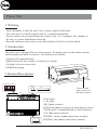
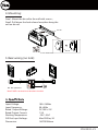
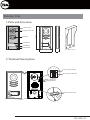
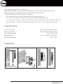
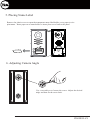
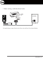
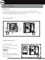
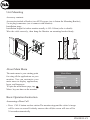
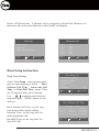
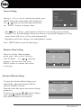
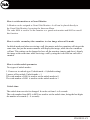
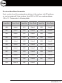
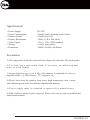
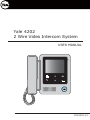
Yale 4202
2 Wire Video Intercom System
USER MANUAL
YDV4202-V1
Power Unit
1. Warning
- Don’t dismantle or alter the unit. Fire or electric shock could result.
- The unit must be installed and wired by a qualified technician.
- Do not connect any non specified power source to the N, L terminals, Fire, damage to
the unit, or system malfunciont can result.
- Keep the unit away from water or any other liquid, risk of fire or electric shock.
2. Introduction:
The power unit is designed for two wire systems. It supplies power to the outdoor station,
indoor monitor and other accessories. The features are as follow:
• Universal AC input/full range
• Multi protection: sho rt circuit, overload, over voltage
• Cooling by free air convection
• DINrail mounting
60m m
3. Terminal Description:
90
mm
N
N
L
SW
PA P- P+
CN2
LED
BUS(IM) BUS(DS)
CN1
140mm
* Press on both
sides of the cover
and lift to remove
N: AC input.
L:AC input.
SW: Swit ch termina l.
LED: Power indicator,always on when plug in p ower.
CN2: PA and P+ terminal should be sho rt-circuited.
CN1: Buscontrol termina l.
BUS(IM): Indoor monitor conne ction termina l.
BUS(DS): Door st
ation conne ction termina l.
YDV4202-V1
4. Mounting:
Step1: Mount the din rail to the wall with screws ;
Step2: Pull down the lock release lever,then hang the
unit on din rail.
Din rail
Din rail
Lock release lever
5. Basic wiring (no lock):
2
BUS BUS
(DS) (IM)
NP
NP: Non-polarized
PA P- P+
L1
L2
N
L
2
NP
L1
L2
AC~
Note:PA&P+ terminal must be short-circuited.
Input Voltage:
Input Frequency:
Rated Output Voltage:
Rated Output Current:
Working Temperature:
SW Port Input Voltage:
Dimension:
100~240Vac
50~60Hz
DC 28V+/-2V
1.5A
-100C~500C
Max.230Vac, 2A
140*90*60mm
YDV4202-V1
Exterior Unit
1.Parts and Functions
Camera Lens
Speaker
176 mm
Night View LED
Nameplate
Call Button
Microphone
Rain Cover
90 mm
23 mm
2.Terminal Descriptions
ON
1 2
Lock Control Jumper
Doorstation Code DIP
1 2
ON
1 2 3
MIC adjustment
SPK adjustment
BUS
S2+ SPL S1+
Main Connect Port
YDV4202-V1
• Lock Control Jumper: Not to be removed
• Doorstation Code DIP: To be used when additional exterior units are used in the same system.
• Main Connect Port: To connect the interior monitor and electornic lock/s.
BUS: Connection to interior monitor, no polarity.
PL: External lock power input, connect to the power positive(power +).
S1+, S2+: Lock power(+) output. To locks can be connected through the unit.
S-: Lock power(-) output, connect to the power(-) input of locks only when using the camera to
power the locks, if using the external power supply for the locks, the S- will not be connected).
3. Specification
Lock Power supply:
12Vdc, 300mA(Internal Power)
Power Consumtion:
NO, COM dry contact:
1W in standby, 12W in working
Max. 48V dc 1.5A
Unlocking time:
Working temperature:
1 to 9 seconds, set by Monitor
-10ºC ~ 45ºC
4.Mounting
1
2
3
4
1
2
160-165cm
YDV4202-V1
5. Placing Name Label
Remove the plastic cover to open the transparent name label holder, cut a paper to size
print name. Insert paper on to name holder re insert plast cover back to the panel
ON
1 2
Backside
name label
6. Adjusting Camera Angle
Use a screwdriver to loosen the screw. Adjust the desired
anlge and then fix the screw back.
YDV4202-V1
7. Basic wiring (with electronic lock)
ON
1 2
AC~
monitor
BUS(IM) BUS(DS)
BUS(DS)
BUS PLS1+ S2+ S-
BUS(IM)
+
Use supplied plugs to connect Exterior unit to Power unit, and Power Unit ot Interior Monitor.
YDV4202-V1
Interior Monitor
Introduction
The monitor is designed with a 4 inch screen, it provides a resolution of 320x240
pixels with high quality image display, and it is equipped with a handset to communicate
The touch sensitive button makes the operation easy.
Parts and Function
Microphone
Mounting Hook
LCD Screen
Handset
MENU Button
Connection Port
Up Button
Memo Button
Handset
Handset Line
ON
1
2
3
UNLOCK Button
Down Button
Cancel Button
Mounting Hook
Monitor Button
Handset Line
Speaker
Front view
Back view
Terminal Description
Bit1: reserve
Bit2: reserve
Bit3: to set the video impendance
L1
L2
SW+
SW-
L1,L2: Bus terminal
SW+,SW-: Door bell call button
connection port
DIP switches: Total 3 bits can be
DIP
ON
1
2
3
ON
1
2
3
matching. When video signal quality
is low, set bit3 to “on”.
YDV4202-V1
Unit Mounting
Accessory contents:
145~160 cm
Accessories include a Bracket, two 4X25 screws (use to fasten the Mounting Bracket),
2 wire plug/connectors (use to connect with Monitor).
Installation steps:
Installation height for indoor monitor usually is 145~160cm (refer to sketch).
Wire the cable correctly, then hang the Monitor on mounting bracket firmly.
About Main Menu
The main menu is your starting point
for using all the applications on your
monitor. You can customize your
main menu to display applications,
logos, and languages.
To open the main menu page, tap
Menu key one time on the monitor.
Main Menu
Monitor ...
Manual Monitor
Intercom
User Setup
Close
About
OK
Select Item
Basic Operation Instruction
Answering a Door Call
• Press CALL button on door station.The monitor rings,and the visitor’s image
will be seen on screen.If nobody answers the call,the screen will turn off in
30 seconds automatically.
YDV4202-V1
• Pick up handset to talk with the visitor, the talking duration time is 90s. To en the
conversation, hang up the handset. If the system connects two or more monitors,
puck up any handset, the others will be automatically shut off.
Door Release
During a call, press
UNLOCK button to open the door for the visitor.
Entrance Monitoring
When the monitor is in standby mode, press MONITOR button (or select Monitor item
on main menu page), The screen will display the outside image.
To end the monitoring, press MONITOR button again.
Intercom Function
Intercom function can be initiated by any monitor when multi monitors are installed.
When the monitor is in standby mode, pick up handset, the Intercom menu will be
highlighted in the main menu page. Press MENU button to enter.
Intercom Call: User in one apartment can call other apartments in the system.
Select a name on the screen, using the / buttons to move up/down to select name,
then press MENU button to dial.
Note:
1. Press "MENU " button again to redial.
2.The address of each monitor must set different
Innercom: If multi Monitors are installed in the same apartment, select Inner
Call; all the other Monitors will ring at the same time. Whichever Monitor answers
the call, conversation is started and the other monitors will stop ringing.
YDV4202-V1
Direct Call Guard unit: A Monitor can be assigned as Guard Unit Monitor, so a
intercom call can be placed directly to the Guard Unit Monitor.
Intercom Call
Intercom
Intercom Call ...
Inner Call ...
Direct Call Guard Unit ...
Exit
OK
Select Item
[ 00 ]
[ 01 ]
[ 02 ]
[ 03 ]
[ 04 ]
[ 05 ]
Joe
Alex
Mike
Susan
Mary
Tony
Exit
xt
Calling
Next Page
Basic Setup Instruction
Ring Tone Setting
Select User Setup item on main menu
page to enter setup page. Select
Door
Station Call Tone , Intercom Call
Tone or Door Bell Tone menu. There
are 12 ring tone that can be selected.
Use
/
button to select last/next
ring tone, press MENU button to save
and exit.
Door Station Call Tone: set the ring
tone from outdoor station calling.
Intercom Tone: set the ring tone for
other apartments calls.
DoorBell Tone: set the ring tone for
door bell calls.
User Setup (1)
Door Station Call Tone ...
Intercom Call Tone ...
DoorBell Tone ...
Clock ...
Next Page
Exit
OK
Select Item
Door Station Call Tone
Selected:
1 Carmen
2 Ding Dong
3 Rain
4 For Alice
Cancel
06
5 Sonatine
9 Do Re Me
6 Edelweiss
10 Happy Birthday
7 Going Home
11 Jingle Bells
8 Congratulation 12 Telephone Ring
Save&Exit
Last/Next
YDV4202-V1
Screen Setting
Scene
Bright
Color
Select Camera ...
During a c a l l o r w h e n monitoring ouside, press
MENU button, the adjust menu will be displayed.
Use
/ button to select the adjust menu item,
use M E N U button to change values.
Brightly
6
6
Exit
Select Item
Inc
• The
item is Scene mode selection: Total of 4 screen modes can be selected:
Normal, User, Soft and Bright. Please note whenever you modify Brightness or Clour
menu, Scene will be set to User mode automatically
• Brightness and Colout: change color and brightness settings.
Press MENU button to quit the adjust page.
Monitor Time Setting
Select User Setup item on main
menu page, then select Monitor
Time Set Menu. Use
/
button to
increase / decrease the value, press
MENU button to confirm and return
to last page.
Monitor Time Select
Current :
Cancel
01min
Save&Exit
Last/Next
Advanced Menu Setting
To enter the Advance Menu Setting, press
and hold the
unlock button unitl the
Advanced Mode is entered.
Enter the codes that appear on screen to change
parameters.
To enter codes, use the / button to change
value, and
MEMO for next value.
Press MENU button to save and exit.
Code Number:[0000]
[0010]:Remove remote
[8000]:Master 0
[8004]:Guard unit
[8006]:Panel on as slaver called
[8010]:Unlock mode 0
[0011]:Add remote
[8001]~[8003]:Slaver 1~3
[8005]:Not guard unit
[8007]:P
[8011]:Unlock mode 1
[8021]~[8029]:Unlock time set 1~9s
[8100]~[8199]:Language select 0~99
[8200]~[8231]:Local address set as 0~31
YDV4202-V1
How to set the monitor as a Guard Monitor
A Monitor can be assigned as Guard Unit Monitor. A call can be placed directly to
the Guard Unit Monitor, bypassing the Intercom Menu.
The code 8004 is used to set the monitor as a guard unit monitor and 8005 to cancell
this function.
How to set the secundary/slave monitors to view image when call is made
In default mode and when receiveing a call, the master and slave monitors will ring at the
same time, but just the master monitor will display the image, while the slave monitors
will not. This setting can be changed to have all the monitors (master and slave), dispaly
the image at the same time while receiving a call by using the code 8006 on each slave
monitor.
How to set the unlock parameter
Two types of unlock modes:
1. Power-on- to-unlock type: Unlock mode = 0 (default setting)
2.power-off-to-unlock: Unlock mode = 1
The code number of 8010 is used to set the unlock mode to 0
The code number of 8011 is used to set the unlock mode to 1
Unlock time:
The unlock time can also be changed. It can be set from 1 to 9 seconds.
The code number from 8021 to 8029 are used to set the unlock time, being the last digits
the number of seconds (1~ 9 seconds).
YDV4202-V1
2 locks control:
The monitor can be set to control 2 locks while you should set the unlock2 item to "on "
state.
The code number of 8015 is used to set the unlock2 OFF. This setting is for only one lock.
The code number of 8014 is used to set the unlock2 ON. This setting is to control two locks.
Note: During a call or while monitoring outside,
press UNLOCK button. Two unlock icons will be
showed. Use
/
button to select the
lock you want, and press UNLOCK or
MENU button to release the corresponding
door, press
to exit.
Restore to default operation will not
change this parameter.
1
2
How to set the slave monitor address
Maximum 4 monitors can be connected in one apartment, one master monitor
together with 3 slave monitors. Monitor address should be set correctly
(one monitor must be set as master monitor)
Code 8000 is used to set the master monitor.
Code 8001 is used to set the first slave monitor.
Code 8002 is used to set the second slave monitor.
Code 8003 is used to set the third slave monitor.
Language mode setting
This monitor can support multiple languages. To change the language, input the
corresponding language code. The language code number are as follows:
8101: English
8102: French
8103: Spanish
8104: Italian
8105: German
8106: Dutch
8107: Portuguese
8108: S-Chinese
8109: T-Chinese
8110: Greek
8111: Turkish
8112: Polish
8113: Russian
8114: Slovakia
8115: Hungry
8116: Czech
8117: Hebrew
......
Note:the monitor can only support 4 types of languages.English,French,Spanish and
German are default.
YDV4202-V1
How to set the address for monitor
Each monitor should be assigned an address in the system, total 32 addresses can be assigned. Code numbers from 8200 to 8231 are used as address
00 to 31. Please refer to following table:
Input No.
User Code
Input No.
User Code
Input No.
User Code
8200
Code=0
8211
Code=11
8222
Code=22
8201
Code=1
8212
Code=12
8223
Code=23
8202
Code=2
8213
Code=13
8224
Code=24
8203
Code=3
8214
Code=14
8225
Code=25
8204
Code=4
8215
Code=15
8226
Code=26
8205
Code=5
8216
Code=16
8227
Code=27
8206
Code=6
8217
Code=17
8228
Code=28
8207
Code=7
8218
Code=18
8229
Code=29
8208
Code=8
8219
Code=19
8230
Code=30
8209
Code=9
8220
Code=20
8231
Code=31
8210
Code=10
8221
Code=21
YDV4202-V1
Specifications
•
•
•
•
•
•
•
Power Supply:
Power Consumption:
Monitor Screen:
Display Resolutions:
Video Signal:
Wiring:
Dimension:
DC 24V
Standby 6mA; Working status 194mA
4 Inch color LCD
320(R, G, B) x 240 pixels
1Vp-p, 75Ω, CCIR standard
2 wires, non-polarity
186(H)×190(W)×26(D)mm
Precautions
1) All components should be protected from drops and vibrations. Do not drop unit.
2) To clean, use a soft cotton cloth. If necesary, use mild soap and
water to wash lightly.
3) Image distortion may occur if the video monitor is mounted too close to
magnetic fields e. g. Microwaves, TV, computer etc.
4) Please keep away the monitor from water, high temperature, dust, caustic
and oxidation gas in order to avoid any unpredictable damage.
5) P o w e r s u p p l y m u s t b e s u p p l i e d o r a p p r o v e d b y m a n u f a c t u r e r
6) Risk of electric shock if unit is oppened. Please refer service only to qualified and
trained professionals.
YDV4202-V1