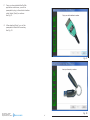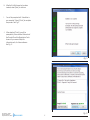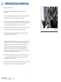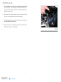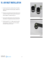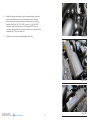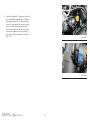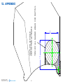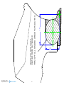
1
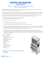
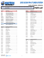
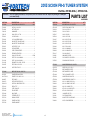
2013 Scion FR-S and Subaru BRZ Supercharger System Installation Instructions 2013 MODEL YEAR* *Legal in California only for racing vehicles which may never be used upon a highway. 1650 Pacific Avenue, Channel Islands, CA., 93033-9901 • Phone: 805 247-0226 • Fax: 805 247-0669 • vortechsuperchargers.com • M-F 7:00AM - 3:30PM (PST) DP/N: 4TF020-010 - v2.1 05/14/2013 FOREWORD This manual provides information on the installation, maintenance and service of the Vortech supercharger kit expressly designed for this vehicle. All information, illustrations and specifications contained herein are based on the latest product information available at the time of this publication. Changes to the manual may be made at any time without notice. Contact Vortech Engineering for any additional information regarding this kit and any of these modifications at (805) 247-0226 7am-3:30pm PST. Take note of the following before proceeding: 1. Proper installation of this supercharger kit requires general automotive mechanic knowledge and experience. Please browse through each step of this instruction manual prior to beginning the installation to determine if you should refer the job to a professional installer/technician. Please contact your dealer or Vortech Engineering for possible installers in your area. 2. This product was designed for use on stock (un-modified, OEM) vehicles. The PCM (computer), engine, transmission, drive axle ratios and tire O.D. must be stock. If the vehicle or engine has been modified in any way, check with Vortech prior to installation and use of this product. 3. Use only premium grade fuel with a minimum of 91 octane (R+M/2). 4. Always listen for any sign of detonation (knocking/pinging) and discontinue hard use (no boost) until the problem is resolved. 5. Vortech is not responsible for any clutch, transmission, drive-line or engine damage. Exclusions from Vortech warranty coverage considerations include, but not limited to: 1. Neglect, abuse, lack of maintenance, abnormal operation or improper installation. 2. Continued operation with an impaired vehicle or sub-system. 3. The combined use of Vortech components with other modifications such as, but not limited to, exhaust headers, aftermarket camshafts, nitrous oxide, third party PCM programming or other such changes. ©2013 VORTECH ENGINEERING, INC P/N: 4TF020-010 v2.1, 05/14/2013 ©2013 Vortech Engineering, Inc All Rights Reserved, Intl. Copr. Secured All rights reserved. No part of this publication may be reproduced, transmitted, transcribed, or translated into another language in any form, by any means without written permission of Vortech Engineering, Inc. ii TABLE OF CONTENTS FOREWORD...........................................................................................................................................................ii TABLE OF CONTENTS.......................................................................................................................................iii TOOL & SUPPLY REQUIREMENTS................................................................................................................v PARTS LIST, 4TF218-014L & 4TF218-114L.................................................................................................vi 1. ECU RE-FLASH (COMPLETE KITS ONLY).........................................................................................1 2. PREPERATION/REMOVAL.......................................................................................................................8 3. MOUNTING BRACKET AND SUPERCHARGER INSTALLATION ..............................................10 4. CHARGE AIR COOLER INSTALLATION ............................................................................................18 5. MAF HARNESS EXTENSION ..................................................................................................................25 6. WINDSHIELD WASHER RESERVOIR INSTALLATION .................................................................27 7. CHARGE AIR COOLER TUBE INSTALLATION ................................................................................31 8. COMPRESSOR BYPASS VALVE INSTALLATION ............................................................................34 9. PCV VALVE INSTALLATION ...................................................................................................................35 10. AIR INLET INSTALLATION ......................................................................................................................36 11. FINAL CHECK................................................................................................................................................39 12. APPENDIX .....................................................................................................................................................40 INTERACTIVE PDF This is an interactive Adobe PDF. Clicking on the table of contents takes you to your desired page. All photos or drawings contained within link to higher resolution versions found on our server. You will be told you are being directed to an outside source. P/N: 4TF020-010 v2.1, 05/14/2013 ©2013 Vortech Engineering, Inc All Rights Reserved, Intl. Copr. Secured iii COPYRIGHT NOTICE This product is protected by state common law, copyright and/or patent. All legal rights therein are reserved. The design, layout, dimensions, geometry and engineering features shown in this product are the exclusive property of Vortech Engineering, Inc. This product may not be copied or duplicated in whole or part, abstractly or fundamentally, intentionally or fortuitously, nor shall any design, dimension, or other information be incorporated into any product or apparatus without prior written consent of Vortech Engineering, Inc. P/N: 4TF020-010 v2.1, 05/14/2013 ©2013 Vortech Engineering, Inc All Rights Reserved, Intl. Copr. Secured iv SCION FR-S AND SUBARU BRZ Installation Instructions Congratulations on selecting the best performing and best backed automotive supercharger available today... the VORTECH® Supercharger! Before beginning this installation, please read through this entire instruction booklet and the Street Supercharger System Owner's Manual which includes the Automotive Limited Warranties Program and the Warranty Registration form. Vortech supercharger systems are performance improving devices. In most cases, increases in torque of 30-35% and horsepower of 35-45% can be expected with the boost levels specified by Vortech Engineering. This product is intended for use on healthy, well maintained engines. Installation on a worn-out or damaged engine is not recommended and may result in failure of the engine as well as the supercharger. Vortech Engineering is not responsible for engine damage. Installation on new vehicles will not harm or adversely affect the break-in period so long as factory break-in procedures are followed. For best performance and continued durability, please take note of the following key points: 1. Use only premium grade fuel 91 octane or higher (R+M/2). 2. The engine must have stock compression ratio. 3. If the engine has been modified in any way, check with Vortech prior to using this product. 4. Always listen for any sign of detonation (pinging) and discontinue hard use (no boost) until problem is resolved. 5. Perform an oil and filter change upon completion of this installation and prior to test driving your vehicle. Thereafter, always use a manufacture-rated, high grade engine oil or a high quality synthetic, and change the oil and filter every 3,000 miles or less. Never attempt to extend the oil change interval beyond 3,000 miles, regardless of oil manufacturer's claims as potential damage to the supercharger may result. 6. Before beginning installation, replace all spark plugs that are older than 1 year or 30,000 miles with original heat range plugs as specified by the manufacturer and reset timing to factory specifications (follow the procedures indicated within the factory repair manual and/or as indicated on the factory underhood emissions tag). Do not use platinum spark plugs unless they are original equipment. Change spark plugs every at least 30,000 miles and spark plug wires at least every 50,000 miles. TOOL & SUPPLY REQUIREMENTS • • • • • • • • • • • • Factory Repair Manual 3/8" Socket and Drive Set: SAE & Metric Adjustable Wrench Open End Wrenches: SAE & Metric Flat #2 Screwdriver Phillips #2 Screwdriver Drill Motor 1/4" Drill Bit Tin snips or light-duty grinder Wire Strippers and Crimpers Utility Knife Soldering gun and solde ® If your vehicle has in excess of 30,000 miles since its last spark plug change, then you will also need: • Spark Plug Socket • NEW Spark Plugs P/N: 4TF020-010 v2.1, 05/14/2013 ©2013 Vortech Engineering, Inc All Rights Reserved, Intl. Copr. Secured v ING ER INE G EN . C , IN 2013 SCION FR-S TUNER SYSTEM Part No. 4TF218-014L / 4TF218-114L IMPORTANT: Before beginning installation, verify that all parts are included in the kit. Report any shortages or damaged parts immediately. PART NO. 008110 008130 008447 009035 2F369-014 4TF020-010 4TF110-044 4TF112-010 4TF212-030 8N101-354 5A001-130 4TF212-030 4TF010-160 4TF010-170 4TF010-180 4TF012-060 4TF112-030 4TF112-040 4TF112-050 5W001-032 5W001-095 5W022-020 5W022-030 5W022-040 5W022-060 5W022-250 7A250-051 7C040-008 7C060-013 7C060-016 7C060-026 7E014-075 7F006-093 7F106-080 7J006-093 DESCRIPTION...............................................QTY SMALL SILVER DIE CUT DECAL.................................. 2 LICENSE PLATE FRAME, VORTECH........................... 1 1 YR S/C STRT INFO PKG ASY VOR........................... 1 S/C LUBE, BOTTLED, VORT 3-PACK.......................... 1 S/C ASY, 2013 SCION FR-S........................................... 1 INSTR MAN, 2013 SCION FR-S BRZ............................ 1 MTG BRKT ASSY, 2013 SCION FR-S........................... 1 AIR INLET ASSY, 2013 SCION FR-S............................. 1 DISCH ASSY, 2013 SCION FR-S................................... 1 CHARGE AIR COOLER, SCION FR-S.......................... 1 4TF218-014L ONLY INCLUDES BELOW ITEMS TUNING KIT ASSEMBLY, ECUTEK............................... 1 DISCH ASSY, 2013 SCION FR-S................................... 1 TAB, PANL SUPPORT......................................................................... 2 BRACKET, TUBE D.............................................................................. 1 MNT TAB, DISCH TUBE A................................................................... 1 DISCH TUBE B ................................................................................... 1 DISCH TUBE A ASSY.......................................................................... 1 DISCH TUBE C ASY............................................................................ 1 DISCH TUBE D ASSY.......................................................................... 1 1/4" PLASTIC WIRE LOOM.............................................................. 48" 1/8" HT-SHRINK TUBING.................................................................1.5' 22GA STRD WIRE,BLACK..................................................................4' 22GA STRD WIRE, RED.....................................................................4' 22GA STRD WIRE,GREEN.................................................................4' 22GA STRD WIRE, BLUE....................................................................4' 22GA STRD WRE WH/BLU.................................................................4' 1/4-20 X .50 HHCS ............................................................................. 4 M4-.7X8MM SCHD SS......................................................................... 2 M6 X 1.0 X 12MM FLG HD ................................................................. 2 M6 X 1.0 X 16 HXHD........................................................................... 2 M6 X 1.0 X 25MM, FLG HD................................................................. 4 #14 X .75 HEX HD SHEETMETAL SC................................................ 4 NUT, M6 X 1.0, NYLOCK..................................................................... 7 NUT PLATE, 2X M6............................................................................. 1 6MM WASHER....................................................................................11 P/N: 4TF020-010 v2.1, 05/14/2013 ©2013 Vortech Engineering, Inc All Rights Reserved, Intl. Copr. Secured vi PARTS LIST PART NO. 4TF212-030 7J250-001 7P375-156 7P375-378 7PS251-250 7PS251-300 7PS300-250 7PS301-175 7R002-016 7R002-036 7R002-048 7R003-008 7R004-002 7R009-012 7U030-046 7U034-016 7U314-004 8D001-004 8H040-075 8N010-420 8N010-430 7U030-056 7P375-156 DESCRIPTION...............................................QTY DISCH ASSY, 2013 SCION FR-S.......................... cont’d. 1/4 WASHER, SA................................................................................. 4 3/8"X3/8"X5/32"MALE BARB TEE....................................................... 1 VALVE, CHECK, 3/8 BARB X 3/8 ....................................................... 1 SLEEVE, 2.5"D X 2.5"L STRAIGHT..................................................... 3 SLEEVE, 2.5"D X 3"L BUMP............................................................... 2 REDUCER, BLK 3.0-2.50.................................................................... 1 SLEEVE, 3"D X 1.75"L STRAIGHT...................................................... 1 #16 SAE TYPE F SS HOSE CLAMP................................................... 2 #36 SAE TYPE F SS HOSE CLAMP................................................. 14 #48 SAE TYPE F SS HOSE CLAMP................................................... 3 ADEL CLAMP, 1/2" ID.......................................................................... 1 STEPLESS CLAMP, 17.0-70................................................................ 2 CLAMP, SPRING, .75"......................................................................... 2 5/32" VACUUM LINE............................................................................3' 1" GS HTER HOSE.......................................................................0.208' LORD MOUNT, RUBBER M6 X 1" OD................................................ 1 COMPRESS BYPASS VALVE, G2....................................................... 1 FILTER, 1" BYPASS VALVE................................................................. 1 BRKT, CAC UPPER, RIGHT................................................................ 1 BRKT, CAC UPPER, LEFT.................................................................. 1 3/8" HOSE........................................................................................... 5" 3/8" X 5/32 TEE.................................................................................... 1 4TF112-010 008358 4TF010-070 4TF010-080 4TF010-090 4TF010-121 4TF013-010 4TF013-020 4TF110-060 4TF110-100 4TF110-130 7C060-013 7C060-026 AIR INLET ASSY, 2013 SCION FR-S............................................... DECAL, INLET................................................................................... BRACKET, LID................................................................................... BRKT, AIR BOX MOUNT, LEFT......................................................... BRKT, AIR BOX MOUNT, CENTER................................................... BRKT, AIRBOX SPPRT...................................................................... AIRBOX.............................................................................................. AIRBOX LID....................................................................................... BULKHD ASSY.................................................................................. BRKT ASY, AIR BOX, RH.................................................................. ASY, PROP ROD RELOC BRKT....................................................... M6 X 1.0 X 12MM FLG HD................................................................ M6 X 1.0 X 25MM, FLG HD............................................................... 1 1 1 1 1 1 1 1 1 1 1 9 1 2013 SCION FR-S TUNER SYSTEM Part No. 4TF218-014L / 4TF218-114L IMPORTANT: Before beginning installation, verify that all parts are included in the kit. Report any shortages or damaged parts immediately. PARTS LIST CONTINUED PART NO. 4TF112-010 7F006-093 7F106-080 7J006-093 7J625-125 7P500-001 7P500-009 7R002-056 7R002-080 7S500-351 7U008-010 7U008-012 7U008-014 7U030-050 7U100-004 7U100-006 7U100-065 7U188-375 8H040-050 DESCRIPTION...............................................QTY AIR INLET ASSY, 2013 SCION FR-S.......................................cont’d. NUT, M6 X 1.0, NYLOCK................................................................... 3 NUT PLATE, 2X M6........................................................................... 2 6MM WASHER................................................................................... 4 SHIM, .625" ID X .13" THK................................................................ 2 1/2" HOSE UNION............................................................................. 1 1/2" X 90 HOSE BARB UNION.......................................................... 1 #56 SAE TYPE F SS HOSE CLAMP................................................. 1 #80 SAE TYPE F SS HOSE CLAMP................................................. 1 INLET SLEEVE, 5 X 3.5.................................................................... 1 Q-TURN FASTENER......................................................................... 2 PLATE, Q-TURN FASTENER............................................................ 2 RETAINER, Q-TRN FSTNR............................................................... 2 12MM (1/2") FUEL HOSE........................................................ 0.762M RIVET, 3/16 X 3/16, ALUMINUM....................................................... 2 RIVET, 1/8 X 3/16, ALUMINUM......................................................... 4 GROMMET, .5"ID, .812"OD, .187" GRV............................................ 1 TAPE, FOAM, 3/16" X 3/8" W ........................................................ 36" AIR FILTER 3.5"FLG X 7"L................................................................ 1 4TF110-044 2A017-462 2A017-750-016 2A046-975 4FA016-171 4FH016-150 4TF010-011 4TF010-021 4TF010-031 4TF010-041 4TF010-050 4TF017-011 4TF017-021 4TF017-031 MNTG BRKT ASSY, 2013 SCION FR-S........................................... SPACER,IDLER SMOOTH 6RIB....................................................... SPACER .75 OD X .328 ID X .160.................................................... BELT, K060975................................................................................... DUST COVER (IDLER PULLEY)....................................................... IDLER PULY, SMOOTH 6RIB 3" FLG................................................ BRKT, ALT TILT.................................................................................. PLATE, S/C MOUNT.......................................................................... STAY, MTG BRKT.............................................................................. MOUNT, BASE................................................................................... STIFFENER, MTG PLT...................................................................... BUSHING, ALT BRKT........................................................................ SPACER, DUAL THRD...................................................................... SPACER, MAIN BRKT....................................................................... P/N: 4TF020-010 v2.1, 05/14/2013 ©2013 Vortech Engineering, Inc All Rights Reserved, Intl. Copr. Secured 1 1 2 1 1 1 1 1 1 1 1 1 1 2 vii PART NO. 4TF110-044 4TX016-150 7A312-124 7A312-500 7A375-127 7A375-129 7C010-027 7C010-059 7C010-093 7C012-040 7C060-020 7C060-026 7F312-017 7J006-093 7J312-875 7U375-055 DESCRIPTION...............................................QTY MNTG BRKT ASSY, 2013 SCION FR-S.................................. cont’d. IDLER, 2.75 DIA, SMOOTH, 7 RIB................................................... 1 5/16-18 X 1.25 FLG HD..................................................................... 2 5/16-18 X 5" HX HD........................................................................... 1 3/8-16 X 1.25 SHCS.......................................................................... 1 3/8-16 X 1.25 FLG HD....................................................................... 7 M10 X 1.25 X 25 FLG HD.................................................................. 1 M10 X 1.25 X 50 FLG HD.................................................................. 2 M10 X 1.25 X 90 FLG HD.................................................................. 2 M12 X 1.75 X 40 HXHD..................................................................... 1 M6 X 1.0 X 20MM HHCS .................................................................. 2 M6 X 1.0 X 25MM, FLG HD............................................................... 2 5/16-18 NYLOCK NUT....................................................................... 1 6MM WASHER, PLATED................................................................... 4 5/16" WASHER, 7/8" OD, CUSTOM.................................................. 2 5/8" VACUUM CAP FOR .625 NIP.................................................... 1 4TF155-021 4CJ017-021 4TF010-190 4TF010-200 4TF014-010 4TF055-021 4TF055-041 7C060-013 7C060-026 7C080-022 7F006-093 7F008-023 7J250-001 7J312-000 7R002-020 7U034-020 WASHER RESERVOIR ASY, SCION FR-S....................................... 1 SPACER, COIL, .625" X .45" LO....................................................... 1 BRKT, WASHER RES, UPPER......................................................... 1 BRKT, WASHER RES, LOWER......................................................... 1 TUBE, 1.25" WASHER FILL PIPE..................................................... 1 WASHER RES CAP, SCION FR-S.................................................... 1 WASHER RESERVOIR, SCION FR-S............................................... 1 M6 X 1.0 X 12MM FLG HD CL10.9+................................................. 3 M6 X 1.00 X 25MM FLG HD, PLATE................................................. 1 M8 X 1.25 X 20 BHCS, PLTD............................................................ 4 NUT, M6 X 1.0, NYLOCK, PLATED................................................... 1 NUT, M8 X 1.25 NYLOCK NUT......................................................... 4 1/4 WASHER, SAE, PLTD................................................................. 1 5/16 FLAT WASHER-SAE.................................................................. 8 #20 SAE TYPE F SS HOSE CLAMP................................................. 2 HOSE, 1.25 DIA RUBBER RAD........................................................ 4 1. SOFTWARE INSTALLATION AND ECU RE-FLASH (COMPLETE KITS ONLY. TUNER KITS SKIP AHEAD TO STEP 2) NOTE: Prior to attempting to install any portion of the supercharger system and re-flash the ECU, it is important to confirm that your vehicles’ ECU is supported by the EcuTek components included in your kit and to get any available updates. This will require that you have a computer with an internet connection so that you can download and install the free EcuTek software. A laptop is suggested, as you will need to connect the computer to the vehicles’ OBD2 port using the supplied cable after the downloads have completed. Please read through and understand this step COMPLETELY before proceeding with anything related to the installation. A. Visit the EcuTek Website: www.ecutek. com. Click on the [Downloads] tab. See arrow in Fig 1A. Fig. 1A P/N: 4TF020-010 v2.1, 05/14/2013 ©2013 Vortech Engineering, Inc All Rights Reserved, Intl. Copr. Secured 1 B. After you have selected the [Downloads] tab, select [EcuTek App Downloader] in the next window. See arrow in fig 1B. C. After you have selected [EcuTek App Downloader], you will be prompted with a new window. Select [Next] to continue. Fig 1C. Fig. 1B P/N: 4TF020-010 v2.1, 05/14/2013 ©2013 Vortech Engineering, Inc All Rights Reserved, Intl. Copr. Secured Fig. 1C 2 D. Next, you will be prompted to install the necessary software and drivers. It is recommended to use the default settings. If you have Adobe Reader installed, you can uncheck this part of the installation. Select [Next] to continue. See Fig 1D. E. It is recommended that you agree with Windows security warnings if they appear as shown below. Select [Install] to continue. See Fig 1E. Fig. 1D P/N: 4TF020-010 v2.1, 05/14/2013 ©2013 Vortech Engineering, Inc All Rights Reserved, Intl. Copr. Secured 3 Fig. 1E F. Once you have installed the EcuTek application and drivers, you will be prompted to plug in the vehicle interface cable. Select [Next] to continue. See Fig 1F. G. After selecting [Next], you will be prompted to insert the license key. See Fig. 1G Fig. 1F P/N: 4TF020-010 v2.1, 05/14/2013 ©2013 Vortech Engineering, Inc All Rights Reserved, Intl. Copr. Secured 4 Fig. 1G H. After the EcuTek license key has been inserted, select [Next] to continue. I. You will be prompted with “Installation is now complete”. Select [Finish] to complete the process. See Fig. 1I. J. After selecting [Finish], you will be prompted by a new window. Make note of the Dongle ID and the Registration Code shown on your screen. Keep this information safe, for future reference. See Fig. 1J. Fig. 1I P/N: 4TF020-010 v2.1, 05/14/2013 ©2013 Vortech Engineering, Inc All Rights Reserved, Intl. Copr. Secured 5 Fig. 1J K. Select [Download Now!]. You will see a new window appear that will show progress and details of what is being downloaded. This can take a few minutes, so please be patient. See Fig. 1K. L. When the download has completed, you will be prompted with a new window. M. Select [OK] to continue. Installation of the EcuTek ProECU software is now complete. See Fig. 1L ECU re-flash: NOTE: Programming an ECU is the process of taking a ROM file and placing it into permanent storage inside the ECU. It is highly recommended that all non-essential vehicle devices are switched off before attempting to program an ECU. This helps to minimize electrical interference to vehicle systems that may conflict with communication between the EcuTek components and the ECU. For devices within the car, this includes: headlights, interior lights, A/C, HVAC fan and any other powered devices. Fig. 1K N. Confirm that your laptop computer is booted up and the EcuTek ProECU application is running. The laptop must be plugged into a power source. Do not rely on the laptop battery power. O. Insert the supplied USB flash drive inth the laptop computer. Copy and save the file located on the flash drive onto your computer in the following folder location: C:\EcuTek\ProECURomFiles\Subaru\BRZ P. Plug the EcuTek OBD2 vehicle interface cable into the vehicles OBD2 diagnostic socket. The socket is located beneath the lower section of the dashboard just above the drivers throttle pedal. Q. Connect the other end of the EcuTek vehicle interface cable to a USB port on the laptop computer. Fig. 1L R. ‘Key-On’ the vehicle ignition. DO NOT START the engine. P/N: 4TF020-010 v2.1, 05/14/2013 ©2013 Vortech Engineering, Inc All Rights Reserved, Intl. Copr. Secured 6 S. In the ProECU software menu bar (at the top of the window): Select ‘Tools’, then > ‘Detect Vehicle’. A new window will appear with ‘Program Engine ECU’ highlighted. Select [OK]. T. Select [Program ECU] in the following window. It will take a few minutes for this process to complete. After programming the ECU, follow the on-screen instructions to cycle the ignition ON, OFF etc. It is important that this is done in sequence with the appropriate time delays as directed. U. The message ‘Programming Sequence completed’ should appear. Select [Ok]. The re-flash step is now complete. NOTE: It is possible that you will come across an ECU version that EcuTek has not seen. It will not be possible for you to program this ECU until EcuTek has been supplied with certain information about the specific ECU. The ‘Dump Details for EcuTek’ button saves certain information from this ECU. The information is stored in a file that will be saved into the ‘C:\EcuTek\RomDumps’ folder. The name of the file will be displayed as it is saved. This information should be sent to EcuTek using the Website Form, together with a clear photograph of the ECU label and details of the type of car (please include Model Year and Manual or Auto gearbox) from which the ECU originates. EcuTek will then supply an updated version of ProECU that will be capable of programming the ECU. You will then need to send the new file received from EcuTek over to Vortech with your Dongle ID and License Key to have the revised calibration completed. Please note that it is not something that can be done while-youwait. Turnaround time is likely to be 3 to 7 days for support of a new ECU. It is therefore important for the tuner to check that the ECU version is supported well before the car is scheduled to be reprogrammed – this will avoid a panic situation for all parties involved. Please note that it is not possible to open ROM Dumps in ProECU until the file has been emailed to EcuTek. P/N: 4TF020-010 v2.1, 05/14/2013 ©2013 Vortech Engineering, Inc All Rights Reserved, Intl. Copr. Secured 7 2.PREPARATION/REMOVAL A. Place car on vehicle lift. B. Raise hood and use appropriate fender covers for paint protection. C. Unpack the new accessory drive belt to let the “bends” relax. This is best done in a warm room rather than a cold shop. D. Locate the hose coming from the firewall that leads to the air filter resonator system and disconnect at the first 90° fitting near the firewall. Cap fitting with supplied 5/8” cap. See Fig. 2A. E. Disconnect the opposite end at the resonator. Remove the entire assembly from the vehicle, as it will no longer be used. Fig. 2A F. Disconnect the crankcase breather hose from the 90° plastic fitting in the rubber air inlet duct. G. Unplug the Mass Air Flow (MAF) connector from the MAF sensor located on the air filter lid. Disconnect the rubber inlet duct from the throttle and remove it with the air filter lid and set aside. Unfasten the air filter box at the three mounts and remove. Remove and save the rubber cushion mount assemblies and hardware for reinstallation in a later step. The duct and other air filter box components will not be reused. H. Remove the plastic belt covers from both the alternator and the A/C compressor. Set aside covers and mounting hardware for re-installation in a future step. I. De-tension the belt tensioner and remove the accessory drive belt. The belt will not be used with the supercharger system. P/N: 4TF020-010 v2.1, 05/14/2013 ©2013 Vortech Engineering, Inc All Rights Reserved, Intl. Copr. Secured 8 Scion FR-S models only: J. This procedure is to make room for the charge cooler ducts to pass through. The connectors should be secured with nylon tie-wraps after the modification has been made and the ducts are in place. K. Behind each headlight assembly, the main electrical connector lays in a cradle extending from the assembly. L. Pull the connector from the assembly and place aside (do not disconnect the connector). M. With a one-inch drum grinder [in a drill or Dremel], remove 80-90% of the cradle. See Fig. 2B. Fig. 2B P/N: 4TF020-010 v2.1, 05/14/2013 ©2013 Vortech Engineering, Inc All Rights Reserved, Intl. Copr. Secured 9 3. MOUNTING BRACKET AND SUPERCHARGER INSTALLATION MODIFY BOSS AS SHOWN A. Temporarily loosen the shorter mounting bolt on the outboard side of the alternator. Remove the longer bolt on the opposite side. Rotate the inboard side of the alternator upwards. Modify (file or carefully grind) the OEM alternator bracket boss. See Fig. 3A. B. Place the supplied alternator tilt bracket into position. See Fig. 3B. C. Loosely reinstall the long OEM bolt in the upper position through the new bracket, then the new 5/16” x 5” bolt with thick washer provided into the lower position. Insert the supplied bushing into the rear of the lower tilt bracket hole. Slide the remaining thick washer and nylon lock nut onto the end of the 5/16” screw. After the alternator has been tilted and all three bolts are lightly snug, torque the bolts per OEM specification. Fig. 3A Fig. 3B P/N: 4TF020-010 v2.1, 05/14/2013 ©2013 Vortech Engineering, Inc All Rights Reserved, Intl. Copr. Secured 10 D. Remove the two lower OEM A/C mount bolts. Attach the mounting bracket support with the provided M10 x 50mm bolts and secure as shown. Note that the spacer is positioned toward the left side of the support. See Fig. 3C. E. Remove the grooved (1) and smooth (2) OEM idler pulleys from the front engine cover and set aside. See. Figs. 3D, 3E. IDLER PULLEY AND HARDWARE REMOVED Fig. 3D Fig. 3C P/N: 4TF020-010 v2.1, 05/14/2013 ©2013 Vortech Engineering, Inc All Rights Reserved, Intl. Copr. Secured IDLER PULLEY AND HARDWARE REMOVED 11 Fig. 3E F. Replace the smooth idler located just above the crank damper pulley with the supplied 2.75” diameter steel pulley. Secure the pulley with the supplied M10 x 25mm screw (for clearance purposes, do not re-use the OEM screw). See Fig. 3F. G. The supercharger assembly comes mounted to the supercharger mounting plate with a smooth idler installed along with a drain hose connected. There is a loose, captured screw in one of the mounting plate holes as well. See Figs. 3G, 3H. REPLACEMENT IDLER AND SCREW M12 x 1.25 x 90 SCREWS Fig. 3F P/N: 4TF020-010 v2.1, 05/14/2013 ©2013 Vortech Engineering, Inc All Rights Reserved, Intl. Copr. Secured Fig. 3G 12 Fig. 3H H. Check over the supercharger bracket assembly for loose fasteners and fittings. One of the fasteners will remain captured, but loose (see previous photo). Place the two of the previously removed OEM idlers back into their former positions (smooth pulley below the A/C compressor and grooved pulley beneath the alternator) without the dust washers or screws. Temporarily place the two main bracket spacers with the new M10-1.25x90 fasteners through the idler pullies and into the mounting bosses loosely. Temporarily hold the supercharger/plate assembly in front of the engine and familiarize yourself with the relative placement of the components. Using the belt routing guide graphic and photo as a guide, route the belt around the accessory pulleys as shown, leaving slack for the supercharger and its attached smooth idler pulley. See Figs. 3I, 3J. Fig. 3I Fig. 3J P/N: 4TF020-010 v2.1, 05/14/2013 ©2013 Vortech Engineering, Inc All Rights Reserved, Intl. Copr. Secured 13 3/8-16 x 1.25” SCREW I. Leaving the idler pulleys in place, remove the main bracket spacers and bolts and place them in position on the supercharger mounting plate assembly with the M10 x 90mm bolts. Place the assembly on to the engine, loosely route the belt around the supercharger and idler pulleys (not the alternator) and thread the 10mm bolts into their pulley supports and lightly snug the screws. Thread the 3/8 x 1.25” bolt into the support located beneath the A/C clutch. Loosely attach the mounting bracket support onto the alternator tilt bracket with the two 5/16 x 1.25” fasteners (lightly snug; do not tighten). Thread the 3/8 x 1.25” bolt (captured in the supercharger mounting plate) into the end of the support and tighten. See Figs. 3K, 3L, 3M. Fig. 3K 5/16-18 x 1.25” SCREWS Fig. 3L 3/8-16 x 1.25” SCREW P/N: 4TF020-010 v2.1, 05/14/2013 ©2013 Vortech Engineering, Inc All Rights Reserved, Intl. Copr. Secured 14 Fig. 3M J. Torque all mounting fasteners. Finish installing the accessory drive belt by fully retracting the tensioner and correctly routing per the belt routing diagram. Note: final installation of the belt is made easiest by routing over the top of the alternator pulley LAST. See Fig. 3N. K. Remove the two OEM screws near the cam covers as shown. See Fig. 3O. Fig. 3N L. Loosely attach the supplied steel mounting plate stiffener behind the supercharger mounting plate with the supplied M6x 25mm screws. Sandwich the supplied .16” thick aluminum spacers (1 per hole) between the other side of the stiffener bracket and the threaded holes near the cam covers with the M6 x 20mm long fasteners and washers provided. Tighten hardware. See Fig. 3P. REMOVE TWO OEM CAM COVER SCREWS Fig. 3O P/N: 4TF020-010 v2.1, 05/14/2013 ©2013 Vortech Engineering, Inc All Rights Reserved, Intl. Copr. Secured 15 Fig. 3P M. Mount the supplied airbox support bracket to the tab located on the driver side frame rail using the supplied M6 x 12 screw. See Fig. 3Q N. Locate the supplied hood prop rod relocation bracket assembly. See Figs. 3R and 3S for final position. Temporarily locate the bracket onto the fender mount flange with the OEM prop rod inserted in the clip. Using the bracket as a drill template, align the assembly into the desired position for best fit and mark where the mounting holes are to be drilled into the fender mount flange. Carefully drill two (2) 1⁄4” holes through the flange. Remove sharp edges from around the hole edges and mount the hood prop rod relocation bracket assembly as shown using the supplied M6 x 12 screws. Fig. 3Q O. Locate the plastic OEM belt covers previously removed from the A/C compressor and alternator. Fig. 3R P/N: 4TF020-010 v2.1, 05/14/2013 ©2013 Vortech Engineering, Inc All Rights Reserved, Intl. Copr. Secured 16 Fig. 3S P. Re-install the alternator cover using the original hardware. The A/C cover will require modification so as to clear the supercharger and belt. Modify the cover and re-install using the original hardware. See Fig. 3T Fig. 3T P/N: 4TF020-010 v2.1, 05/14/2013 ©2013 Vortech Engineering, Inc All Rights Reserved, Intl. Copr. Secured 17 4. CHARGE AIR COOLER INSTALLATION A. Raise the car and remove the lower plastic cover panels from below the engine and front bumper cover. See Fig. 4A. B. Using a round file, lengthen the three fastener slots in the panel rearward about 1/8th of an inch (3mm), as the panel sits in the car. See Fig. 4B. C. Carefully remove the front bumper cover from the vehicle (retain all hardware and note location of each screw for future re-installation): 1. Remove four (4) fasteners each side attaching the inner fender liner to edge of the front bumper cover. Remove the fasteners securing each fender liner to the bottom side of the bumper cover. 2. Reach up and un-plug the marker and fog light connectors from behind the front bumper cover. 3. Carefully remove the marker lights (secured with 2 spring clips) from where each side of the fender meets the bumper cover. Remove the fastener securing the corner of the bumper cover to the fender. 4. Remove the hardware attaching the top edge of the front bumper cover to the vehicle. Fig. 4A Fig. 4B 5. Ensure that all hardware securing the bottom portion of the front bumper cover has been removed. Carefully remove the front bumper cover and place it in a safe location. D. Remove the windshield washer fluid tank and filler. P/N: 4TF020-010 v2.1, 05/14/2013 ©2013 Vortech Engineering, Inc All Rights Reserved, Intl. Copr. Secured 18 E. Temporarily remove the two plastic side panels from either side of the cooling air feed cavity. These panels need to be modified to accommodate the CAC ducts. Find the two (left and right-side) 1:1 paper templates in the back of this manual. Use the templates to mark the modifications and then, using heavy-duty shears, modify the panels per the markups. Set aside. See Figs. 4C, 4D. Fig. 4C Fig. 4D P/N: 4TF020-010 v2.1, 05/14/2013 ©2013 Vortech Engineering, Inc All Rights Reserved, Intl. Copr. Secured 19 F. Remove the horn from in front of the A/C condenser. G. Flatten the OEM horn locating tab. See Figs. 4E, 4F, 4G. Fig. 4E Fig. 4F P/N: 4TF020-010 v2.1, 05/14/2013 ©2013 Vortech Engineering, Inc All Rights Reserved, Intl. Copr. Secured 20 Fig. 4G H. Remove the OEM fastener as shown (passenger side), and relocate the horn to the newly “shared” position. Re-attach connector. See Figs. 4H, 4I. Fig. 4H Fig. 4I P/N: 4TF020-010 v2.1, 05/14/2013 ©2013 Vortech Engineering, Inc All Rights Reserved, Intl. Copr. Secured 21 I. Temporarily remove the lower OEM 6mm bolt from the center support then loosen (do not remove) the two bolts at the top of the support just below the radiator. See Fig. 4J. J. Attach the supplied charge cooler upper mounting brackets to the sides of the CAC using the 1⁄4"-20 x 1⁄2" screws with washers. Note left and right positions. Do not tighten the screws at this time. See Figs. 4K, 4L. Fig. 4J Fig. 4L P/N: 4TF020-010 v2.1, 05/14/2013 ©2013 Vortech Engineering, Inc All Rights Reserved, Intl. Copr. Secured 22 Fig. 4K K. With the slot mount at the bottom rear of the charge-cooler, temporarily lift the charge-cooler into place. Have an assistant pull down on the OEM support to allow the cooler to fit in place. Place the slot mount on the CAC over the support upper flange. Replace the lower bolt on the support. See Fig. 4M. L. On the top, outboard corners of the charge-cooler are the upper mounting brackets. Carefully position the cooler so as to be centered, and parallel with the A/C condenser, then adjust the upper mounting brackets (they are slotted for adjustment). Fig. 4M M. Mark the holes to be drilled for the upper mounts into the bottom of the OEM bumper beam. Reverse the process with the center support and remove the charge-cooler. Center-punch the marks and drill four 3/16” mounting holes into the OEM bumper beam. P/N: 4TF020-010 v2.1, 05/14/2013 ©2013 Vortech Engineering, Inc All Rights Reserved, Intl. Copr. Secured 23 N. Again, lift the cooler into place and secure with the four #14 hex-head self-tapping fasteners provided. Secure the upper mounting bracket fasteners and center support. See Figs. 4N, 4O, 4P. Fig. 4N P/N: 4TF020-010 v2.1, 05/14/2013 ©2013 Vortech Engineering, Inc All Rights Reserved, Intl. Copr. Secured Fig. 4O 24 Fig. 4P 5. MAF HARNESS EXTENSION NOTE: Complete (non-tuner) kits include a plug-and-play MAF extension harness (Vortech p/n 5W001-094). Disregard the following "cut and solder" portion of this step if you have a MAF extension harness. Simply plug the extension into the vehicle harness and route down to the relocated MAF module. Connect to the MAF module and secure wires from sharp edges. Fig. 5A A. Locate the Mass Air Flow (MAF) sensor harness previously attached to the airbox cover. See Fig. 5A. B. Carefully remove the electrical tape securing the plastic split loom and expose the five wires. See Fig. 5B. C. Cut the five wires just above the shielding of the white wire (approximately 2" from the connector). Be sure to leave enough wire to be stripped and soldered on each end. See Fig. 5C. P/N: 4TF020-010 v2.1, 05/14/2013 ©2013 Vortech Engineering, Inc All Rights Reserved, Intl. Copr. Secured Fig. 5B 25 Fig. 5C D. Using the provided wires, solder wire extensions onto the harness. Seal solder joints with heat shrink tubing. See Fig. 5D. E. Route the modified MAF under the throttle body and under the intake manifold and away from the alternator. See Fig. 5E. F. Continue to route the harness and connector over to the passenger side headlight, and down behind the bumper cover. Fig. 5D G. Secure the harness with nylon ties insuring that the harness is away from hot or sharp objects. Fig. 5E P/N: 4TF020-010 v2.1, 05/14/2013 ©2013 Vortech Engineering, Inc All Rights Reserved, Intl. Copr. Secured 26 6. WINDSHIELD WASHER RESERVOIR INSTALLATION A. Locate the OEM windshield washer reservoir assembly removed in a previous step. B. Separate the filler neck, filler neck grommet, washer pump and washer pump grommet from the main tank. The tank will not be re-used. C. Cut the excess length from the filler neck. Remove any plastic burrs from the cut edge. Discard the portion no longer connected to the cap end of the tube. See Fig. 6A, 5B. D. Install the supplied length of Ø1.25” hose onto the end of the filler neck and secure with supplied #20 clamp. See. Fig. 6C. Fig. 6B Fig. 6A P/N: 4TF020-010 v2.1, 05/14/2013 ©2013 Vortech Engineering, Inc All Rights Reserved, Intl. Copr. Secured 27 Fig. 6C HOOD LATCH CABLE LOCATION E. Remove the OEM hood release cable retainer from the chassis mounting hole. See Fig. 6C. F. Attach the modified filler neck and hose to the vehicle. Use the supplied M6 x 12 screw with washer and nut to secure the assembly into to the hole previously occupied by the hood release cable. Align as shown. See Fig. 6D. SUBARU BRZ APPLICATIONS ONLY: • Instead of the M6x12 screw, use the supplied M6x25 screw and .45" space between the filler neck tab and chassis mount. See Fig. 6D-1. Fig. 6C • Use a file to lightly clearance corner of headline housing as shown See Fig. 6D-2. (SUBARU BRZ ONLY) Fig. 6D-1 (SUBARU BRZ ONLY) Fig. 6D-2 Fig. 6D P/N: 4TF020-010 v2.1, 05/14/2013 ©2013 Vortech Engineering, Inc All Rights Reserved, Intl. Copr. Secured 28 G. Insert the OEM filler neck grommet into the 1.43” hole in the supplied tank. Ensure that it is seated properly. Apply a very small amount of white grease or similar lube onto the inside diameter of the grommet. Insert the non-beaded end of the supplied metal tube into the grommet just far enough until the end starts to push through the grommet on the inside of the tank. See Fig. 6E. Fig. 6E H. Using the supplied M8 screws, nuts and washers, install the new mounting brackets to the reservoir. See Fig. 6F. I. Insert the OEM washer pump grommet into the 1.37” hole in the supplied tank cap. Ensure that it is seated properly. Apply a very small amount of white grease or similar lube onto the inside diameter of the grommet. Insert the OEM washer pump into the grommet until seated. Install the cap/ pump assembly onto the tank. Ensure that the cap gasket is in place and the cap is snug. Rotate the pump and orient as shown. See Fig. 6G. P/N: 4TF020-010 v2.1, 05/14/2013 ©2013 Vortech Engineering, Inc All Rights Reserved, Intl. Copr. Secured Fig. 6F 29 Fig. 6G J. Drop the remaining #20 hose clamp over the metal tube. Attach the new tank assembly to the vehicle using two of the original chassis mount locations and the supplied M6 x 16 screws. See Figs. [6H, 6I). As the assembly is being installed, ensure that the metal filler tube is inserted into the rubber filler hose. Secure the connection with the #20 hose clamp. K. Re-attach the OEM washer hose and connector to the washer pump. The pump wiring harness may need to be separated from the main harness in order to get the connector to reach the new pump location. Do this by carefully opening up the plastic harness cover with a razor blade. Be careful not to cut into any of the wire insulation. Re-tape and cover the original harness. Fig. 6H L. Fill the reservoir with appropriate washer fluid until the level can be seen in the filler neck. Fig. 6I P/N: 4TF020-010 v2.1, 05/14/2013 ©2013 Vortech Engineering, Inc All Rights Reserved, Intl. Copr. Secured 30 7. CHARGE AIR COOLER TUBE INSTALLATION NOTE: On Subaru BRZ models, the passenger side headlight must be removed in order to properly install the charge cooler tubes. A. Locate the supplied discharge tube 'B' (simple 90 degree bend) and slide a 2-1/2" silicone sleeve and pair of #36 clamps on each end of the tube. Attach the long leg of the tube to the driver side of the CAC. Temporarily snug the clamps so the tube does not fall out, but can still be moved slightly. See Fig. 7A. Fig. 7A B. Locate the supplied discharge tube 'A' (with welded 1” boss attached). From the top, slide discharge tube 'A' behind the left (driver side) headlight and into the sleeve on discharge tube 'B'. Attach discharge tube 'A' to the supercharger with the “bump” sleeve and #36 clamp provided. See Fig. 7B. C. Secure tube 'A' to the previously installed airbox support bracket using the #36 clamp, mount tab, M6 screw, washers and nuts. See Fig. 7C. Fig. 7B Fig. 7C P/N: 4TF020-010 v2.1, 05/14/2013 ©2013 Vortech Engineering, Inc All Rights Reserved, Intl. Copr. Secured 31 D. Locate the supplied discharge tube 'C' (MAF flange attached) and OEM MAF module previously removed. Ensure that the o-ring is intact on the MAF module. Insert the MAF sensor module into the flange and secure with the supplied M4 fasteners. On the passenger side, connect discharge tube 'C' to the CAC using the supplied 3” x 2-1/2” reducer sleeve and clamps. Install a “bump” sleeve onto the remaining open end of the tube after it is in place. See Fig. 7D. E. Attach the supplied mounting tab to the supercharger mounting bracket using the screws and nut plate. See Fig. 7E. Fig. 7D F. Thread the supplied rubber mount into tube 'D'. See fig. 7F. Fig. 7E P/N: 4TF020-010 v2.1, 05/14/2013 ©2013 Vortech Engineering, Inc All Rights Reserved, Intl. Copr. Secured 32 Fig. 7F G. Install the supplied 3” dia. x 1.75” sleeve and #48 clamps onto the throttle body. Locate the supplied discharge tube 'D'. Attach the tube between the throttle body sleeve and the “bump” sleeve. The stud on the rubber mount will mate with the previously installed mounting tab. Adjust tube to ensure adequate clearance to the drive belt. Install the M6 locknut with washer onto the mount stud. Tighten all clamps after all tubes have been aligned and proper clearance adjustments have been made throughout the charge tube route. See Fig. 7G. Fig. 7G H. Re-install the two previously modified plastic OEM side panels from into the cooling air feed cavity into their OEM positions. Secure the bottom portion of the panels to the CAC tubes using the supplied mount tabs, M6 x 16 screws, nuts, washers and clamps. See Figs. 7H, 7I. I. Connect extended MAF harness connector to MAF module on tube ‘C’. J. Reinstall the headlight (if removed), bumper cover and lower plastic cover panels. P/N: 4TF020-010 v2.1, 05/14/2013 ©2013 Vortech Engineering, Inc All Rights Reserved, Intl. Copr. Secured Fig. 7H 33 Fig. 7I 8. COMPRESSOR BYPASS VALVE INSTALLATION A. Install the supplied compressor bypass valve onto the 1” nipple on discharge tube A using the short section of 1” hose provided. Secure with #16 clamps. Attach 1” filter to open end of bypass valve and secure. See Fig. 8A. B. Attach the supplied length of 5/32” hose to the small port on the bypass valve. Route the hose over to where the OEM brake booster hose attaches to the intake manifold. C. MANUAL TRANSMISSION ONLY - Using the supplied brass branch tee, splice into the brake booster hose approximately 2” from where it attaches to the manifold. Reconnect hose. Attach 5/32” bypass hose to the open port in the tee. See Fig. 8B. Fig. 8A D. AUTOMATIC TRANSMISSION ONLY - Remove the OEM vaccum cap located at the top of the intake manifold on the driver side. Attach the supplied 5” length of 3/8” rubber hose to the open manifold port. Insert one of the 3/8” legs of the supplied tee into the hose and then cap the remaining 3/8” leg on the tee with the OEM cap previously removed. Attach the 5/32” bypass hose to the open port in the tee. See Fig. 8C. (Manual transmission models only) Fig. 8B (Auto transmission models only) Fig. 8C P/N: 4TF020-010 v2.1, 05/14/2013 ©2013 Vortech Engineering, Inc All Rights Reserved, Intl. Copr. Secured 34 9. PCV VALVE & MAP SENSOR INSTALLATION A. Locate the OEM breather hose connecting the top on the intake manifold to the passenger side of the engine. B. Splice-in the supplied breather hose check valve into the OEM hose. NOTE FLOW DIRECTION on the valve (flow direction is toward the intake manifold). Secure with stepless clamps provided. See Fig. 9A,9B, 9C. C. COMPLETE (NON-TUNER) SYSTEMS ONLY: Replace the OEM MAP Sensor with the supplied unit. See Fig. 9D. P/N: 4TF020-010 v2.1, 05/14/2013 ©2013 Vortech Engineering, Inc All Rights Reserved, Intl. Copr. Secured 35 Fig. 9A Fig. 9C Fig. 9B Fig. 9D 10. AIR INLET INSTALLATION A. Locate the supplied airbox assembly and two of the rubber cushion mount spacers and screws originally installed in the OEM airbox. B. Temporarily remove the steel inserts from the rubber cushion mount spacers. Install the cushion mounts into the center of the two supplied 5⁄8" ID spacers. See Fig. 9A. Fig. 10A C. Insert two of the rubber cushion mounts into the mounting tabs attached to the supplied airbox assembly. See Fig. 9B. D. Attach the supplied 5” x 3-1⁄2” rubber coupler to the inlet of the supercharger. Loosely place one each of the supplied #80 and #56 clamps onto the sleeve. Fig. 10B P/N: 4TF020-010 v2.1, 05/14/2013 ©2013 Vortech Engineering, Inc All Rights Reserved, Intl. Copr. Secured 36 E. Install the airbox assembly onto the supercharger inlet and vehicle. Align the airbox to the mounting holes, forward facing inlet duct and previously installed airbox mounting bracket. See Figs. 10C, 10D, 10E. Use two (2) of the OEM screws to secure the airbox to the forward OEM mount locations. Secure the tab located on the driver side using the supplied M6 x 20 screw and nut. Fig. 10C F. Tighten hose clamps at supercharger interface. Fig. 10D P/N: 4TF020-010 v2.1, 05/14/2013 ©2013 Vortech Engineering, Inc All Rights Reserved, Intl. Copr. Secured 37 Fig. 10E G. Insert the supplied 1⁄2" hose union into the end of the OEM breather hose. Attached the supplied length of 1⁄2" breather hose to the 1⁄2" hose union and route the hose over to the 90° fitting located on the rear of the airbox. Route the hose away from sharp edges and moving objects. Trim hose length if necessary. See Figs. 10F, 10G. Fig. 10F Fig. 10G P/N: 4TF020-010 v2.1, 05/14/2013 ©2013 Vortech Engineering, Inc All Rights Reserved, Intl. Copr. Secured 38 11. FINAL CHECK WARNING: Do not attempt to operate the vehicle until all components are installed and all operations are completed including the final check. A. B. C. If your vehicle has gone over 30,000 miles since its last spark plug change, you will need to change the spark plugs now before test driving the vehicle. Check all fittings, nuts, bolts and clamps for tightness. Pay particular attention to oil and fuel lines around moving parts, sharp edges, and exhaust system parts. Make sure all wires and lines are properly secured with clamps or tie-wraps. Check all fluid levels, making sure that your tank is filled with 91 octane or higher fuel before commencing test drive. For internally lubricated V3 units only This supercharger has been factory pre-filled with special Vortech synthetic lubricant. Oil does not need to be added to a brand new unit, however a fluid level check should be performed. Prior to operating the supercharger on the vehicle and after installation onto the vehicle: Remove the factory installed flat-head brass shipping plug (not the dipstick) from the top of the supercharger case. Replace the sealed shipping plug with the supplied vented plug. Do not operate the supercharger without it. Check the supercharger fluid level using the dipstick as follows: Fluid level checking procedure: 1. Ensure that the .06” copper sealing washer is located on the dipstick base. 2. Thread the clean dipstick into the unit until it seats. D. Start the engine and allow to idle a few minutes, then shut off. 3. Once the dipstick has seated, remove the dipstick from the unit. Fluid should register in the crosshatched area on the dipstick. E. Recheck to be sure that no hoses, wires, etc. are near exhaust headers or moving parts. Look also for any signs of fluid leakage. 4. DO NOT OVERFILL!!! Drain excess fluid from the unit if it is above the maximum level on the dipstick. F. PLEASE TAKE SPECIAL NOTE: Operating the vehicle without ALL of the subassemblies completely and properly installed may cause FAILURE OF MAJOR COMPONENTS. G. Test drive the vehicle. H. Always listen carefully for engine detonation. Discontinue heavy throttle usage if detonation is heard. I. Read the STREET SUPERCHARGER SYSTEM OWNER'S MANUAL AND RETURN THE WARRANTY REGISTRATION FORM within thirty (30) days of purchasing your supercharger system to qualify. P/N: 4TF020-010 v2.1, 05/14/2013 ©2013 Vortech Engineering, Inc All Rights Reserved, Intl. Copr. Secured Check the fluid level using the dipstick at least every 2,500 miles. Initial supercharger fluid change must be performed at 2,500 miles. The supercharger fluid must be changed every 7,500 miles maximum thereafter. Drain the fluid, refill the unit with 4 oz. of Vortech V3 lubricating fluid, and then confirm proper oil level using the dipstick. DO NOT OVERFILL!!! WARNING: Use of any fluid other than the special Vortech lubricant will void the warranty and may cause component failure 39 P/N: 4TF020-010 v2.1, 05/14/2013 ©2013 Vortech Engineering, Inc All Rights Reserved, Intl. Copr. Secured 40 12.APPENDIX 41 P/N: 4TF020-010 v2.1, 05/14/2013 ©2013 Vortech Engineering, Inc All Rights Reserved, Intl. Copr. Secured 1650 Pacific Avenue, Channel Islands, CA., 93033-9901 • Phone: 805 247-0226 • Fax: 805 247-0669 • vortechsuperchargers.com • M-F 7:00AM - 3:30PM (PST)