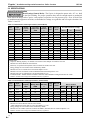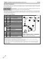
1
Caprice Model Numbers: C85-340 Version Date: 2013-11-20 NEW – OUTDOOR SENSOR Meets Sept. 2012 requirements for “Automatic Means” INSTALLATION AND OPERATION INSTRUCTIONS CAPRICE OIL BOILER Venting Applications: Natural Draft or Direct Vent (Balanced Flue) TABLE OF CONTENTS 1.0 INTRODUCTION ................................................................................................................ 3 2.0 SPECIFICATIONS .............................................................................................................. 6 3.0 BOILER LOCATION .......................................................................................................... 8 4.0 BOILER ASSEMBLY ......................................................................................................... 9 5.0 GENERAL VENTING ....................................................................................................... 12 6.0 NATURAL DRAFT APPLICATIONS .............................................................................. 13 7.0 DIRECT VENT APPLICATIONS ..................................................................................... 17 8.0 BOILER PIPING ................................................................................................................ 24 9.0 FIELD WIRING ................................................................................................................. 26 10.0 INSTALLATION CHECKLIST ........................................................................................ 32 11.0 ANNUAL MAINTENANCE AND INSPECTION ........................................................... 34 12.0 PARTS LIST ...................................................................................................................... 36 13.0 WARRANTY ..................................................................................................................... 39 Caprice C 85- 340 HAZARD SYMBOLS AND DEFINITIONS Danger Sign: Indicates a hazardous situation which, if not avoided, will result in serious injury or death. Warning Sign: Indicates a hazardous situation which, if not avoided, could result in serious injury or death. Caution Sign plus Safety Alert Symbol: Indicates a hazardous situation which, if not avoided, could result in minor or moderate injury. Caution Sign without Safety Alert Symbol: Indicates a hazardous situation which, if not avoided, could result in property damage. Notice Sign: Indicates a hazardous situation which, if not avoided, could result in property damage. This Boiler must be installed by a licensed and trained Heating Technician or the Warranty is Void. Failure to properly install this unit may result in property damage, serious injury to occupants, or possibly death. NTI # 84943 Caprice │ Installation and Operation Instructions C 85-340 Read Before Proceeding If you do not follow these instructions exactly, a fire may result causing property damage, serious injury or death. FOR YOUR SAFETY, READ BEFORE OPERATING_ BEFORE OPERATING: A. Do not start burner unless the smoke hood, clean out door, HydroStat 3250, flue breeching, and burner door (if applicable) are secured in place and the boiler is filled with water. B. Do not attempt to starter burner when excess oil has accumulated in combustion chamber, when unit is full of vapour, or when combustion chamber is very hot. C. Do not use gasoline, crankcase drainings, or any oil containing gasoline. D. Never burn garbage or paper in the unit and never leave combustible material around it. E. Always keep the oil supply valve shut off if the burner is shut down for an extended period of time. F. Do not tamper with the unit or controls - call your service personnel for service and maintenance. G. Do not use this boiler if any part has been under water. Immediately call a qualified service technician to inspect the boiler and to replace any part of the control system and any oil control which has been under water. OPERATING INSTRUCTIONS_ 1. STOP! Read the safety information above very carefully. 2. Initial start-up and start-ups after periods of extended/seasonal shutdown must be performed by a qualified service technician. 3. Check the boiler area for proper clearances. 4. Turn the thermostat(s) up. 5. Turn the emergency power isolation switch on. 6. If ignition does not occur, follow the instructions “To Turn Off Oil Boiler” and call a qualified service technician. TO TURN OFF OIL BOILER_ 1. STOP! Read the safety information above very carefully. 2. Turn off emergency power isolation switch. Should be mounted on the wall near entrance to boiler room. Void Warranty - This Boiler must have water in the boiler whenever the burner is on or it will damage the unit and void the warranty. Failure to follow these instructions may result in serious injury or death. Fuel Oil - Use only No. 2 fuel oil for boiler models listed in this manual. Failure to follow these instructions may result in severe personal injury, property damage, or death. Low Water Cut Off (LWCO) - The HydroStat 3250, when installed in a Caprice or Triton boiler, cannot be used as a LWCO due to it’s location in the boiler; therefore, a standard well is factory supplied with the unit. If a LWCO device is required, an external LWCO must be field installed to provide protection against firing with low water levels. Failure to follow these instructions may result in fire, serious injury or death. Oil Supply Valve - Always keep the oil supply valve shut off if the burner is shut down for an extended period of time. Cold Start Will Void Warranty – Upon power up to the control, increase the LO TEMP setting to a minimum of 120oF. Failure to do so will permit the unit to operate as a cold start boiler and void the warranty. 2 Introduction - Installation & Operation Instructions │ Caprice C 85-340 1.0 INTRODUCTION General Installation Requirements The installation of your NTI Caprice oil boiler shall be in accordance with these instructions and the regulations of the authorities having jurisdiction and must comply with the following codes and standards: United States State and local plumbing, heating, and electrical codes NFPA 70 National Electric Code NFPA 31 Installation Code for Oil Burning Equipment Standard ANSI/ASME CSD-1, Controls and Safety Devices for Automatically Fired Boilers (if applicable) Canada Provincial and local plumbing, heating, and electrical codes CSA C22.1 Canadian Electrical Code Part One CSA B139 Installation Code for Oil Burning Equipment The Caprice boiler is a knock-down boiler constructed of carbon steel. The venting application needs to be decided in advance, either Natural Draft or Direct Vent, prior to ordering the boiler as burner packages will vary depending on the venting application. The boiler package comes in three sections and requires field assembly. Check your boiler package when it arrives and ensure it includes the following: 1. Boiler 2. Jacket 3. Burner Kit This document pertains to the correct installation and operation of NTI Caprice oil boilers for Natural Draft and Direct Vent models. The instructions detailed in this document supersede any and all previous instructions provided by NTI, written or otherwise. The warranty is included in the Installation and Operation manual. Each unit comes complete with the following documentation: 1. Installation and Operating Instructions 2. Users Manual Read and understand this entire document prior to proceeding with the installation of the Caprice. Failure to follow the instructions outlined in this document will result in property damage, serious injury or death. User Responsibilities This boiler must be installed and serviced by a qualified installer or service technician. This boiler must be serviced and inspected annually. As the User/Owner of this equipment, you are responsible for ensuring the maintenance is performed at the required intervals. See “Users Manual”. Failure to have the boiler properly serviced and inspected on a regular basis by a qualified service technician may result in property damage, serious injury or death. Installer Responsibilities As the installing technician it is your responsibility to ensure the installation is performed in accordance with this instruction manual as well as any applicable local or National installation codes. It is also your responsibility to inform the User/Owner of their obligation with respect to the above description under “User Responsibilities”. Failure to follow this warning could result in fire, serious injury, or death. Energy Saving Feature - This boiler is equipped with a feature that saves energy by reducing the boiler water temperature as the heating load decreases. This feature is equipped with an override which is provided primarily to permit the use of an external energy management system that serves the same function. THIS OVERRIDE MUST NOT BE USED UNLESS AT LEAST ONE OF THE FOLLOWING CONDITIONS IS TRUE : An external energy management system is installed that reduces the boiler water temperature as the heating load decreases. This boiler is not used for any space heating. This boiler is part of a modular or multiple boiler system having a total input of 300,000 BTU/hr or greater. This boiler is equipped with a tankless coil. 3 Caprice │ Installation and Operation Instructions - Introduction C 85-340 Natural Draft Applications Natural Draft Applications - All Caprice models are certified as Natural Draft boilers which require a “Chimney System”. The exhaust gases must be vented directly to the chimney. Failure to follow these instructions will result in serious injury or death. Blocked Vent Switch - All Natural Draft Caprice boilers require a Blocked Vent Switch which is factory supplied and packaged with the burner kit and is mandatory in Canada. The Block Vent Switch must be field installed as per the instructions in this manual and the manufacturers instructions included with the switch. Failure to follow the specified instructions may result in fire, property damage, personal injury, or death. Table 1-1 Caprice Boiler Packages (Natural Draft) NYC602 Block Vent Switch Relief Valve OD Sensor Tridicator 81342 83604 13701 82905 83604 13701 82905 81032 81342 305 12501 497 0.85 o 60 B 1.50 o 60 B 0.75 o 70 B NYC601 C85 Well (Standard) F10.C85 HydroStat 3250 3 Nozzle Blast Tube 84024 10630 84654 306 C85.1P2A1 C150.1P2A1 Burner C220 497 F5.C85 305 C85.1G2A1 C220.1H2A1 10618 Jacket Coil 497 0.65 o 60 B 12501 C180 4 C85 F3.C85 84787 C150 4 C85.1F2A1 10632 C85 C95 C105 C125 C1504 C1804 C220 C230 C250 C275 C305 C340 C95 C105 C125 Burner Kit Natural 1 Draft 84787 Becket Burner Riello Burner MODEL Shell Boiler BOILER PART NUMBER 2 Burner kit Contents (Natural Draft) BOILER PACKAGE 3 1.10 o 60 B Notes: 1 Boiler manual packaged with the Burner Kit. 2 Nozzle size included in Burner Kit. See below, “Attention: Nozzle Sizes”. 3 Burner and blast tube comes assembled c/w nozzle specified in this table. Nozzle may need to be changed depending on boiler output. 4 Models C150 and C180 no longer meet minimum efficiency regulations. Nozzle Sizes - The nozzle sent with each respective boiler burner kit is for the minimum firing rate specified for that burner. To obtain a different firing rate, replace the factory supplied nozzle with the appropriate nozzle that meets the desired output. Refer to Tables 2-1 to 2-2 in Section 2.0 for nozzle specifications and performance ratings for Natural Draft boilers. Manufacturer’s Instructions - For complete instructions on installation and control operations, refer to the manufacturer’s instructions included with the Fuel Smart HydroStat 3250, Burner Package, and Blocked Vent Switch. 4 Introduction - Installation & Operation Instructions │ Caprice C 85-340 Direct Vent Applications There are four Caprice models, C95-C150, certified for installation as a Direct Vent boiler. This balanced flue system requires a special venting system in order to pressurize and essentially equalize the inlet and outlet pressure to ensure normal operation. Refer to section “General Venting” and “Specifications” for more details on Direct Vent applications and termination kits. Balanced Flue Applications - Models C95-150 are also certified as Direct Vent boilers and must be ordered as such. Balance flue systems must use the NTI approved venting system. Note that the Direct Vent Terminal and Insulated Flex Pipe are sold separately (see Table 7-2 Direct Vent Kit Components for more details). This “Special Venting System” is designed for pressurized venting with NTI Direct Vent boilers. The exhaust gases must be piped directly to the outdoors using the vent materials and rules outlined in these instructions. Failure to follow these instructions will result in serious injury or death. Table 1-2 Caprice Boiler Packages (Direct Vent) 497 305 NYC804 81662 Burner Direct Vent 4 Kit C85 Relief Valve C95.1R2A4 OD Sensor 81122 Tridicator BF5.C85 Well (Standard) 305 HydroStat 3250 Jacket 497 Nozzle Coil C85 Blast Tube Shell C95.1T2A4 0.85 o 60 B 81342 83604 13701 Table 7-2 0.75 o 70 B 81342 83604 13701 Table 7-2 3,5 12501 C125 12501 C105 84787 C95 84787 Beckett Burner MODEL Burner Kit Direct 1 Vent Riello Burner Boiler BOILER PART NUMBER 2 Burner Kit Contents (Direct Vent) BOILER PACKAGE C1506 C95 C105 3 Notes: 1 Boiler manual packaged with the Burner Kit. 2 Nozzle size included in the Burner Kit. See below, “Attention: Nozzle Sizes”. 3 Burner and blast tube comes assembled c/w nozzle specified in this table. Nozzle may need to be changed depending on boiler output. 4 Direct Vent Terminal not included in Kit. Refer to Table 7-2 for a list of components that must be ordered separately. . 5 Riello BF5 burners are single line gravity feed. See burner manufacturers’ instructions for more details. 6 Model C150 no longer meets minimum efficiency regulations. Manufacturer’s Instructions - For complete instructions on installation and control operations, refer to the manufacturer’s instructions included with the Fuel Smart HydroStat 3250, Burner Package, and Direct Vent Terminal. Nozzle Sizes - The nozzle sent with each respective boiler burner kit is for the minimum firing rate specified for that burner. To obtain a different firing rate, replace the factory supplied nozzle with the appropriate nozzle that meets the desired output. Refer to Tables 2-3 to 2-4 in Section 2.0 for nozzle specifications and performance ratings for Direct Vent boilers. Intakes/Vents - Failure to keep the Vent and Combustion Air Intake clear of ice, snow, and other debris may result in property damage, serious injury, or death. 5 Caprice │ Installation and Operation Instructions - Boiler Location C 85-340 2.0 SPECIFICATIONS Natural Draft Application Draft Settings (Natural Draft) - The Caprice is designed to operate with -.03” w.c. draft in the flue breaching. For proper operation, there must be enough natural or mechanical draft. Due to the design of the Caprice, it may operate at a positive over fire pressure up to +.20 at -.03 draft. Due to installation and equipment variations, recommended air settings are a guideline and will require alteration. See Tables 2-1 and 2-2. Table 2-1 Riello Burners with Caprice Boilers (Natural Draft) Boiler Model C85 Input GPH (US) 0.68 C95 0.75 Heating Capacity MBH 83 91 Net I=B=R Rating Water MBH 72 79 AFUE Efficiency % Pump PSIG 86.8% 86.5% 120 135 Delevan Nozzle Recommended Burner Settings Burner Air Turbulator o F3 5.5 0.0 o F3 5.5 1.0 o F3 5.5 1.5 o 0.60 60 B 0.65 60 B C105 0.85 103 90 C125 1.00 120 104 85.2% 140 0.85 60 B F5 5.5 1.0 C1509 1.25 147 128 83.8% 155 1.00 60oB F5 5.5 1.0 o F5 5.5 4.0 o F10 5.5 0.5 o C180 9 C220 1.50 1.75 174 216 151 188 86.0% 82.5% 86.9% 130 145 135 0.75 60 B 1.25 60 B 1.50 60 B C230 1.85 226 197 86.3% 150 1.50 60 B F10 5.5 1.0 C250 2.00 241 210 85.5% 130 1.75 60oB F10 5.5 1.5 o F10 5.5 2.0 o F10 5.5 3.0 o F10 5.5 4.5 C275 2.25 C305 2.50 2.80 C340 275 304 339 239 264 294 86.9% 86.8% 86.7% 165 155 155 1.75 60 B 2.00 60 B 2.25 60 B General Notes: 1 2 3 4 5 6 7 8 9 Output is “Heating capacity” for models C85-250 and “Gross Output” for models C275-340. Models C85-180 use Riello 40 series burners. Efficiency % represents Steady State in lieu of AFUE for models C275-340. Energy ratings for C85-250 have been confirmed by AHRI. Models C95-105 - F3 burners have an insertion depth of 2.375”. Models C125-180 - F5 burners come assembled with an insertion depth of 2.375”. Models C220-340 - F10 burners have an insertion depth of 2.75”. F10 burner heads - If head carbons on models C220-340, reduce turbulator setting and increase air a little. Models C150 and C180 no longer meet minimum efficiency regulations. Table 2-2 Beckett Burners with Caprice Boilers (Natural Draft) AFUE Heating Net I=B=R Input Boiler Pump Capacity Rating Water Efficiency Model GPH (US) PSIG MBH MBH % C95 0.75 91 79 86.5% 135 C105 0.85 103 90 86.0% 130 C125 1.00 120 104 85.2% 140 Recommended Burner Settings Burner Head Shutter Band MDL1 o 8 1 0.65 70 B (LFB) o 6.5 0 0.75 70 B MDL1 o 8 1 0.85 60 B MDL1 1.25 147 128 83.8% 155 1.00 60 B C150 5 5 Delevan Nozzle o o MDV1 2 C180 2 1.50 174 151 82.5% 145 1.25 60 B MDV1 General Notes: 1 Models C95-180 use Beckett AFG50 series burners. 2 “LFB” indicates the boiler must use a Low Fire Baffle (i.e. C95). 3 Energy ratings for C85-250 have been confirmed by AHRI. 4 Models C95-180 - MDL1 (NYC601) burners and MDV1 (NYC602) have an insertion depth of 3.75. 5 6 Models C150 and C180 no longer meet minimum efficiency regulations. 8 1 10 3 Introduction - Installation & Operation Instructions │ Caprice C 85-340 Direct Vent Application Draft Settings (Direct Vent) - Due to the design of the balanced flue system, the Caprice will operate at a positive draft pressure and a positive over fire pressure at all times. It is designed to operate with a maximum stack draft of 0.25” w.c. and a maximum over fire draft of 0.33” w.c. when little or no wind is present. In extreme wind conditions, the maximum stack draft is 0.35” w.c. and the maximum over fire draft is 0.45” w.c. Due to installation and equipment variations, recommended air settings are a guideline and will require alteration. See Tables 2-3 and 2-4. Insertion Depth (Direct Vent) - See General Notes section in Tables 2-3 and 2-4. Table 2-3 Riello Burners with Caprice Boilers (Direct Vent) Heating Net I=B=R AFUE Boiler Input Pump Capacity Rating Water Efficiency Model GPH (US) PSIG MBH MBH % Delevan Nozzle Recommended Burner Settings Model Air Turbulator o BF5 4.5 0 o BF5 5.5 0 o BF5 4.0 0 o BF5 6.0 1 C95 0.75 91 79 86.5% 135 0.60 60 B C105 0.85 103 90 86.0% 130 0.75 60 B C125 1.00 120 104 85.2% 140 0.85 60 B C1504 1.25 147 128 83.8% 155 1.00 60 B General Notes: 1 2 3 4 Models C85-180 use Riello 40 series burners. Energy ratings for C85-250 have been confirmed by AHRI. Models C95-150 - BF5 burners come assembled with an insertion depth of 2.375”. Model C150 no longer meets minimum efficiency regulations. Table 2-4 Beckett Burners with Caprice Boilers (Direct Vent) AFUE Heating Net I=B=R Input Boiler Pump Capacity Rating Water Efficiency Model GPH (US) PSIG MBH MBH % C95 C105 0.75 0.85 91 103 79 86.5% 90 135 86.0% 130 Delevan Nozzle Recommended Burner Settings Burner Head Shutter Pin o - 4.5 1 o - 6.0 2 0.65 70 B NYC804 0.75 70 B NYC804 General Notes: 1 Direct Vent models C95-150 use the AF11-100 series burners. 2 Energy ratings for C85-250 have been confirmed by AHRI. 3 Models C95 and C105- NYC804 burners come with an AF2-6 head and have an insertion depth of 5.125”. Boiler Characteristics Table 2-5 Caprice Boiler Characteristics Description Boiler Shell Weight [lbs] Boiler Shell C85-180 C220-340 340 400 Fuel Type Water Connections – NPT [in.] No. 2 Oil 1.25 1.25 36 x 20 x 20 42 x 23 x 23 Approx. Boiler Weight with Water [lbs] 465 592 Approx. Boiler Water Content [usg] 15 23 Standard Coil S-4 S-4 Dimensions H x W x D [in.] Electrical Rating 120V / 1Ph / 60Hz / < 12A 7 Caprice │ Installation and Operation Instructions - Boiler Location C 85-340 3.0 BOILER LOCATION In all cases, the Caprice must be installed indoors in a dry location where the ambient temperature must be maintained above freezing and below 100F [38C]. All boiler components must be protected from dripping, spraying water, or rain during operation and servicing. Consider the proximity to the following when determining the best boiler location. System Water Piping Oil Supply Electrical Power Combustion Air / Ventilation Air Chimney Components - Water or flood damaged components must be replaced immediately with new components (see parts list). Failure to do so may result in fire, serious injury, or death. Clearances - Clearances to combustibles represent the minimum clearances required for safety and service. Recommended clearances are for ease of piping installation, annual maintenance, and service access. Refer to Table 3-1 and Figure 3-1. Table 3-1 Minimum Clearances for Installation and Service Model Clearances C85-340 To Combustibles Recommended Front 24 [610] 36 [915] Rear 5 [124] 24 [610] Dimensions - inches [mm] Top Right Side Coil Side 24 [610] 5 [124] 15 [370] 24 [610] 24 [610] 15 [370] Flue Pipe 9 [228] 9 [228] 1, 2 Floor Combustible Combustible Notes: Minimum clearances from flue pipe to combustibles is 9” for single-wall pipe; 6” for double-wall pipe (Type-L). 2 Flue pipe clearances take precedence over all other clearances. 1 Boiler Location - Even if all installation codes are met, good judgment and common sense must also be used when selecting a boiler location. Refer to minimum clearances in Table 3-1 and vent clearances for chimney or direct vent applications. Figure 3-1 Minimum Clearances to Combustibles Flue Pipe, 9” minimum Top 24” Flue pipe clearances take precedence over all clearances, refer to Table 3-1. Rear 5” Right Side 5” Front 24” Coil Side 15” 8 Boiler Assembly - Installation & Operation Instructions │ Caprice C 85-340 4.0 BOILER ASSEMBLY The installation of the boiler shall be in accordance with the authorities having jurisdiction and must comply with Standard CSA B139 (Canada) or NFPA 31 (USA). Fiberglass Materials - Before installing the insulated jacket, read “Handling Instructions” in Section 11.0 and the protective measures recommended when handling fiberglass. Jacket Installation 1. Do not fully tighten screws until jacket assembly is complete. 2. Level the boiler before commencing jacket installation. 3. Remove all protective plastic film on the jacket parts before installing. 4. Fasten front and back panels to the base pan (Figure 4-1). Do not fully tighten screws at this time. 5. Attach sides, positioning them over the front panel, rear panel, and base pan (Figure 4-2). 6. Mount top panels (front and back) over water pipes and smoke hood (Figure 4-3). 7. Fully tighten all jacket screws to secure panels in place. 8. Mount Tridicator and Well on the boiler as shown (Figure 4-4). 9. Position the HydroStat 3250 over well and secure in place from underneath. See instructions included with 10. Insert sensor fully into the well or boiler overheating may occur. See instructions included with HydroStat. Figure 4-1 Front & Rear Panels Figure 4-2 Side Panels Back Panel Right Side Base Pan Front Panel Coil Side Figure 4-3 Top Panels Figure 4-4 Tridicator, Well & HydroStat 3250 Top Front Failure to install the sensor fully into the well may cause boiler overheating resulting in fire, damage, or death. Top Back Standard Well Smoke Hood_ HydroStat 3250 Outlet Tridicator 9 Caprice │ Installation and Operation Instructions - Boiler Assembly C 85-340 Burner Installation The Caprice boiler is designed to work with burners described in this manual. The use of other nozzles, and/or burners, may cause unsafe operation and will void any and all responsibility by NY Thermal for the safety and reliability of the system. The burner kit should be installed in accordance with the instructions in this manual and the burner manufacturer’s instructions included with the burner. Refer to specification Tables 2-1 to 2-4 for nozzle sizes, burner settings, insertion depths, and air setting guidelines. Ceramic Fiber Materials - Before installing the burner, read “Handling Instructions” in Section 11.0 and the protective measures recommended when handling ceramic materials. Fuel Oil - Caprice boilers operate with No. 2 oil as their only approved fuel source. DO NOT USE GASOLINE, CRANKCASE DRAININGS, OR ANY OIL CONTAINING GASOLINE. Failure to follow these instructions may result in severe personal injury, property damage, or death. Combustion Analyzer - To calibrate burner operation, use a calibrated combustion analyzer capable of measuring CO2 and O2 from oil burning boilers Smoke Test - All tests must be done with the burner covers or air intakes in place to simulate normal operation. Smoke Pump - A reliable, certified smoke pump is required to correctly set up this equipment. Avoid Condensation - Due to the high combustion efficiencies and low stack gas temperatures, great care must be taken to ensure the chimney isn’t subjected to flue gas condensation. The gas temperature where the flue pipe enters the chimney must be a minimum of 240oF. Burner Installation Procedure: 1. Burner Package: a. Prepare the burner in accordance with the burner manufacturers instructions included with the burner. b. Refer to specification Tables 2-1 to 2-4 to determine the appropriate nozzle size for the boiler output. See “Attention: Nozzle Sizes” in Section 2.0. c. Riello Burners (extra step required): Mount the burner gasket and burner flange to the boiler. Secure to the boiler using washers and nuts provided (Figure 4-5). Seal around the burner gasket and the blast tube ring with high temperature silicone (i.e. 83ml tube of silicone included in the burner kit). d. Mount prepared burner package to the boiler. Seal around burner flange with high temperature silicone. Combustion Air Settings - Refer to Section 10.0 Installation Checklist for instruction regarding adjusting combustion air settings. Oil Supply Tank and Oil Piping The oil supply tank and piping should be installed in accordance with the instructions in this manual; the burner and pump manufacturer’s instructions; National codes NFPA 31 (USA) or CSA B139 (Canada), and local codes. General Installation Guidelines: 1. Install the oil supply tank as per tank manufacturer’s instructions. 2. Install oil supply piping from the tank to the burner. 3. Recommend installing a low pressure-drop fuel oil filter to prevent burner nozzles plugging at low flow rates. 4. Shut-off valves should be installed to control the flow during operation and to avoid spills during servicing. 5. Oil can be fed from the supply tank by gravity (single pipe system) or by transfer pump (two-pipe lift system). 6. Refer to burner manufacturer’s instructions before installing oil piping systems as some burner packages are not equipped to work with two-pipe lift systems (i.e. Riello BF5). 7. Connect oil supply piping to the fuel oil pump as per the pump manufacturer’s instructions and system type. Pipe Dope / Teflon Tape - DO NOT use on direct oil connection to the fuel pump. Failure to follow instructions may cause valve failure and dangerous operating conditions. 10 C 85-340 Boiler Assembly - Installation & Operation Instructions │ Caprice Figure 4-5 Burner Installation Set insertion depth (Tables 2-1 to 2-4) Blast Tube Ring Burner Gasket Burner Flange Washers and Nuts Blast Tube Burner Prepare the burner as per the burner manufacturer’s instructions. Refer to Tables 2-1 to 2-4 for nozzle sizes, burner settings, insertion depths, air settings, and specifications. 11 Caprice │ Installation and Operation Instructions - General Venting C 85-340 5.0 GENERAL VENTING Natural Draft Applications Caprice models C85-340 are certified as Natural Draft boilers. The Natural Draft installation draws combustion air from the room and uses the stack effect and draft system to exhaust flue gases using a chimney. Air Supply - Allowances for combustion air must be supplied to the appliance space, due to the fact that the heating appliance consumes large volumes of combustion air. In most instances, a permanent opening with an unobstructed or “free area” of 1 square inch for every 1000 BTU’s of input will provide a sufficient amount of combustion air for the boiler to operate properly. If the building is fairly new and relatively air tight, compensate for the air tightness by using a “free area” that is 15% larger that what was calculated above. Do not place the boiler in, or adjacent to, a room where an exhaust fan is operating. Refer to “Combustion Air” in Section 6.0 Natural Draft Applications for more details. Installation must comply with Standard CSA B139 (Canada) and NFPA 31 (USA). Stack Draft - Sufficient draft by natural or mechanical means is necessary for ensuring optimal and consistent operation. The appliance should have a stack draft sufficient to support stable operation. See Draft Settings (Natural Draft). Avoiding Condensation - Due to the high combustion efficiencies and low stack gas temperatures, great care must be taken to ensure that the chimney isn’t subjected to gas o condensation. The exhaust gas temperature where the flue pipe enters the chimney must be a minimum of 240 F or condensation may occur. Draft Regulator - A draft regulator must be used and set to regulate the draft of the boiler. Make sure that the damper is free to operate without sticking, for this will affect the boiler’s combustion system. It is important that the draft be adequate because poor draft conditions will cause poor operation and a possible hazardous condition. Draft Settings (Natural Draft) - The Caprice is designed to operate with a -.03” w.c. draft in the flue breaching; therefore, ensure there is enough natural or mechanical draft for proper operation. Due to the design of the Caprice it may operate at a positive over fire pressure up to +.20 at a -.03 draft. Direct Vent Applications Caprice models C85-150 are also certified for direct vent applications. The Direct Vent installation uses a special venting system where exhaust gases are vented directly to the outside using a special venting system which equalizes the pressure between the air inlet and the flue outlet resulting in a balanced flue system. Refer to Section 7.0 Direct Vent Applications for more details. Installation must comply with Standard CSA B139 (Canada) and NFPA 31 (USA). Draft Settings (Direct Vent) - Due to the design of the balanced flue system, the Caprice will operate at a positive draft pressure and a positive over fire pressure at all times. It is designed to operate with a maximum stack draft of 0.25” w.c and a maximum over fire draft of 0.33” w.c. when little or no wind is present. In extreme wind conditions, the maximum stack draft is 0.35” w.c. and the maximum over fire draft is 0.45” w.c. 12 C 85-340 Natural Draft - Installation & Operation Instructions │ Caprice 6.0 NATURAL DRAFT APPLICATIONS Natural Draft Rules and Guidelines 1. Acceptable Venting Material - Use vent material approved by National Standards NFPA 31 (USA) or CSA B139 (Canada) and local codes. 2. Venting Application - Venting must be connected to a chimney for models operating with Natural Draft. 3. Chimney Condition - Inspect existing chimney before installing new boiler. Deterioration of mortar joints should be repaired prior to using. 4. Chimney Height - Chimney must extend 3’ above the highest point where it exits the roof and 2’ higher than any part of the structure within 10’. 5. Cleaning - Clean chimney, if required; ensure it is clear of any blockages before connecting breeching. 6. Liner Condition - Damaged liner or pipe should be repaired before commencing installation. 7. Minimum Clearances - Observe clearances to combustibles illustrated in Figure 3-1 and Table 3-1: 8. a) Double-wall vent (Type-L) 6 " 9. b) Single-wall vent 9" 10. Chimney Sizes - Minimum chimney sizes should be used. See Table 6-1. 11. Combustion Air - An adequate supply of combustion air must be available to ensure proper combustion. 12. Interlock - If a damper is used to provide make-up air for combustion, it must be interlocked with the burner to prevent the burner starting before the damper is opened. Potential Condensation - Oversized chimneys, outside masonry chimneys, and/or derated inputs can result in flue gases condensing in the chimney. Combustion Air Natural Draft boilers require an adequate amount of combustion air to sustain proper combustion and prevent flue gas leakage. The appliance’s air-inlet draws combustion air from Indoors or Outdoors depending on whether there is a sufficient natural infiltration (air changes) occurring to sustain combustion. If the building is newer and relatively air tight, outdoor air should be considered. For recommended practice, refer to NFPA 31 (USA) or CSA B139 (Canada). Air Circulation - The boiler shall be located so as not to interfere with proper circulation of combustion, ventilation, and dilution air. Make-up Air - The operation of exhaust fans, kitchen ventilation systems, clothes dryers, and fireplaces must be considered in determining the adequacy of a space to provide combustion air requirements. Failure to ensure adequate make-up air to all appliances may result in flue gas leakage, personal injury or death. Permanent Openings for Combustion Air The appliance space or boiler area requires a permanent opening(s) capable of providing adequate combustion air to the boiler. If using two permanent openings, one opening must be within 12 inches of the ceiling, the other within 12 inches of the floor. The minimum dimension of air openings to the appliance space shall not be less than 3 inches in any one direction, including rectangular ducts. Round ducts are connected to the permanent air openings, duct sizes must have a minimum cross-sectional area of 3 inches. See “Sizing Combustion Air Openings” for more details. The minimum size of permanent openings and how combustion air is supplied to them depends on three factors: 1. What is the input capacity of the boiler in Btu/hr? 2. How is the Combustion Air being supplied? 3. Is make-up air required for other appliance in the room competing for the same air? 13 Caprice │ Installation and Operation Instructions - Natural Draft C 85-340 Sizing Combustion Air Openings The following sections detail the three (3) methods for determining the minimum opening size and location required for providing combustion air: 1. Indoor Air - Opening Sizes: Older buildings typically have sufficient ventilation due to air leakage around single pane windows, poorly weather-stripped doors, and non-existent vapour barrier. Indoor air can be used to supply combustion air to the boiler area if the air infiltration rate is adequate, i.e. greater than 0.4 ACH (air changes per hour) or when the boiler area and communicating spaces have a minimum volume of 50 cubic ft per 1000 Btu/hr. If the air infiltration rate is known to be less that 0.4 ACH, refer to the Installation Code for Oil-Burning Equipment for further guidance. a. Combined spaces on the same story minimum free area of openings = 1 in.2/1000 Btu/hr of total input rating of all appliances in the space. not less than 100 sq. in. two openings required - one within 12 in. from ceiling, other within 12 in. from floor or bottom of the enclosure. minimum dimension of air openings shall be not less than 3 in. b. Combined spaces in different stories Volume of spaces in different stories shall be considered as communicating spaces where spaces connected by one or more openings in doors or floors having a total minimum free area of 2 in.2/1000 Btu/hr of total input rating of all appliances. 2. Outdoor Air - Opening Sizes: When outdoor air is used to supply combustion air to the appliance space, both openings must connect directly to the outdoors via ducts or connect to a crawl space or attic that connects freely to the outdoors. Outdoor combustion air provided through opening(s) to the outdoors must be made in accordance with the methods detailed below. a. Two Permanent Openings Method - Two permanent openings shall be provided, one commencing within 12 in. of the top, and the other within 12 in. of the bottom of the enclosure. The openings shall communicate directly, or by ducts, with the outdoors or spaces that freely communicate with the outdoors, as follows: vertical ducts, minimum free area = 1 in.2/4000 Btu/hr of total input rating of all appliances in the space. horizontal ducts, minimum free area = 1 in.2/2000 Btu/hr of total input rating of all appliances in the space. b. One Permanent Opening Method - One permanent opening, commencing within 12 in. of the top of the enclosure, shall be provided. The appliance shall have clearances of at least 1 in. from the sides and back and 6 in. from the front of the appliance. The opening shall directly communicate with the outdoors or shall communicate through a vertical or horizontal duct to the outdoors or spaces that freely communicate with the outdoors and shall have a minimum free area of the following: 1 in.2/3000 Btu/hr of the total input rating of all appliances located in the enclosure. Not less than the sum of the areas of all appliances’ vent connectors in the space. 3. Combination Indoor and Outdoor Air - Opening Sizes: The use of a combination of indoor and outdoor combustion air shall be in accordance with the following: a. Indoor Air - Where used, openings connecting the interior spaces shall comply with opening sizes calculated in accordance with “Indoor Air Opening Sizes” described previously. b. Outdoor Air - Outdoor opening(s) shall be located and sized in accordance with “Outdoor Air Opening Sizes” described previously. c. Outdoor Opening(s) - The outdoor opening(s) size shall be calculated in accordance with the following: The ratio of interior spaces shall be the available volume of all communicating spaces divided by the required volume (i.e. 50 cubic ft per 1000 Btu/hr if 0.4 ACH or greater). The outdoor size reduction factor shall be 1 minus the ratio of interior spaces. The minimum size of outdoor opening(s) shall be the full size of outdoor opening(s) calculated in accordance with “Outdoor Air Opening Sizes” described previously, multiplied by the reduction factor. The minimum dimension of air openings shall not be less than 3 in. 14 C 85-340 Natural Draft - Installation & Operation Instructions │ Caprice Connect Breeching & Blocked Vent Switch Restrictions - Use the minimum vent length and number of elbows possible to ensure flow of combustion gases are not restricted. Failure to follow instructions may result in severe personal injury or death. Blocked Vent Switch - For complete installation details, refer to the manufacturer’s instructions included with the Blocked Vent Switch. The steps for connecting breeching to a chimney are illustrated in Figure 6-1 and should be read in conjunction with the sizes specified in Table 6-1. Restricted flow can result in condensation, flue gas leakage, and/or carbon monoxide emissions. Breeching Installation: 1. Chimney Clearances - Observe clearances to combustibles for breeching and chimney connections. 2. Supports - Install flue pipe brackets according to local codes or as needed. 3. Breeching Sizes- Connect breeching to the boiler flue collar. Use full size breeching when possible. Refer to Table 6-1 for minimum sizes. 4. Potential Restrictions - Keep breeching lengths and elbow-tee combinations to a minimum to avoid restricting the flow of combustion gases. See warning titled “Restrictions”. 5. Chimney Connections - Use thimble or slip joint where breeching enters chimney to allow for removal for cleaning and servicing. 6. Avoiding Obstructions - Ensure breeching does not protrude so far into the chimney that it will cause obstruction. Avoid connecting near the bottom of chimney as blockages may result. 7. Draft Regulator - Ensure damper is level. See instructions included with regulator. 8. Normal Draft Settings - When properly installed, Caprice models are designed to operate with -.03” w.c. draft in the flue breaching. For proper operation, there must be enough natural or mechanical draft. Due to the design of the Caprice, it may operate at a positive over fire pressure up to +.20 at -.03 draft. 9. Draft Gauge (if applicable) - A barometric control can be used to adjust the draft opening by installing it in the breeching. This is optional and typically only done when excessive draft conditions exist which must be relieved or to comply with applicable codes or regulations. 10. Induced Draft Fan (if applicable) - If Natural Draft is insufficient, an induced draft fan may be required if: a. Excessive resistance to combustion gas flow is anticipated. b. Chimney cross-sectional area is smaller than minimum recommended. c. Chimney height is smaller than recommended. d. SideShot Power Venter SS1C is approved with C85-305. See “Parts List” in Section 12.0. 11. Sealing - Seal all vent joints. 12. Blocked Vent Switch - Install switch 6-8” from boiler breeching (Canada). See manufacturer’s instructions. 13. Interlock Set-up - Interlock burner with fan operation before start-up if using a motorized damper to supply outdoor combustion air or induced draft. 15 Caprice │ Installation and Operation Instructions - Natural Draft Table 6-1 Minimum Chimney Sizes Minimum Minimum I=B=R Chimney Model Breaching Rectangular Round Diameter C85 C95 1 C105 5" 6" 8" x 8" C125 C150 C180 1 6" 7" 8" x 8" C220 C230 1 8" x 8" C250 7" 8" C275 2 8 " x 12 " C305 2 8" 10 " C340 8 " x 12 " C 85-340 Minimum Chimney Height Boiler Flue Collar Size 15 ' 6" 15 ' 6" 8" 15 ' 8" 20 ' 8" Notes: 1 6-3/4" x 6-3/4" inside liner. 2 6-1/2" x 10-1/2" inside liner. 3 Excessive breeching length or too many elbows and/or tee will cause restriction. Figure 6-1 Breeching & Blocked Vent Switch Blocked Vent Switch Draft Regulator Blocked Vent Switch Install the switch 6-8” above the boiler breeching, refer to instructions included with kit (mandatory in Canada). Secure breeching using minimum of two screws, equally spaced. 16 C 85-340 Direct Vent - Installation & Operation Instructions │ Caprice 7.0 DIRECT VENT APPLICATIONS Direct Vent Rules and Guidelines 1. Vent Material: Use approved venting material. Refer to Direct Vent Termination Kit in this section. 2. Continuous Vent: The vent must be in one continuous piece with no joints. 3. Balance: Combustion air intake and vent must be installed on the same wall using the specified vent terminal to ensure the system is balanced. 4. Prevailing Winds: Ensure the vent is located where it will not be exposed to normal prevailing winds. 5. Combustion Air-inlet Contamination: Air for combustion must be drawn from an area free of dust and contaminants. Combustion air containing chemicals such as chloride, fluoride, bromine, iodine, or dust and debris will cause corrosion damage of the heat exchanger voiding your NTI warranty. 6. Snow Level Allowance: 24” is the recommended snow level allowance above grade or any surface that will support snow, debris, or ice required for air-inlet / vents in balanced flue systems. If living in a snowfall region, consult your local weather office for the maximum typical snowfall in your area. Example: New Brunswick Canada - typical maximum snowfall is 19”, thus the inlet must be (12”+19”) = 31” above grade. 7. Wall Flashing: Under normal operating conditions this boiler will produce a plume of white gases, and should be taken into consideration when selecting an adequate location. A 36” [915 mm] diameter stainless, plastic, or vinyl shield can be used to flash the exterior of the residence. 8. Flue Gas Hazard: Position the vent termination where vapors cannot make accidental contact with people and pets, damage property, or adjacent buildings. 9. Condensate Hazard: Do not locate vent over public walkways, driveways or parking lots. Condensate could drip and freeze resulting in a slip hazard or damage to vehicles and machinery. 10. Wall Thickness: Direct Vent terminations are designed to work with any standard wall thickness. Installation guidelines for min/max wall thickness are as follows: Min.= 1” [25mm], Max.= 20” [0.5m]. Standard Vent Terminal is 8” long (p/n 81522-1) and Extended Vent Terminal is 20” long (p/n 81522-2). 11. Venting Options: Due to potential moisture loading (build-up) along the exterior wall, sidewall venting may not be the preferred venting option. 17 Caprice │ Installation and Operation Instructions - Direct Vent C 85-340 Direct Vent Clearances Table 7-1 is a quick reference table that is to be read in conjunction with the numbered notes in the table, the Direct Venting Rules and Guidelines, and Figure 7-1. The instructions detailed in this section are a combination of Caprice specific and National Code restrictions. Compliance alone doesn’t ensure a satisfactory installation as good common sense must also be applied. Failure to follow these instructions may result in fire, property damage, serious injury or death. Table 7-1 Termination Clearances Quick Reference Table Clearances to Vent Termination Canada 1 USA 2 Min. Distance Min. Distance 12 in. 305 mm 12 in. 305 mm A Vent Terminal above grade, snow level, or an object that can support snow/ice 3 B Flue gases directed toward / causing damage to masonry, siding, or construction 6 X X X X 4 C To exhaust from any other appliance 6 ft. 1.8 m 12 in. 305 mm D From combustible materials, surrounding building openings, or property lines 9 6 ft. 1.8 m E Below / adjacent operable window or building opening 6 ft. 1.8 m 4 ft. 1.2 m F Above window, door, or building opening. 6 ft. 1.8 m 12 in. 305 mm G To combustion air inlet from any other appliance 6 ft. 1.8 m 12 in. 305 mm 8 H Under a veranda, porch, deck, or balcony 6 ft. 1.8 m I Mechanical air supply inlet to building 5 6 ft. 1.8 m 3 ft. 1.0 m J Soffit, overhang, eave or parapet 2 ft. 610 mm 12 in. 305 mm K Soffit vent; vent opening in overhang 6 ft. 1.8 m 12 in. 305 mm L Inside corner of an L-shaped structure (including walls and fences) 3 ft. 1.0 m 3 ft. 1.0 m M Minimum distance from the oil supply tank’s vent or fill pipe (inlet) 3 ft. 1.0 m 5 ft. 1.5 m N Above a gas meter, gas meter / regulator assembly 4 3 ft. 1.0 m 4 P Each side of center line above or below meters, regulators and vent/relief devices 6 ft. 1.8 m Q Above or adjacent to a paved sidewalk /driveway, or parking lot 7 7 ft. 2.1 m 7 ft. 2.1 m R Above a sidewalk, driveway, or parking lot on public property X X X X S Above a sidewalk, driveway on private property between / serving both dwellings X X X X T Into a canopy or carport X X X X U Above, under or near exterior stairs X X X X Notes: 1 - Canadian installations must comply with the current CSA B139 Natural Oil Installation Code and local codes. 2 - US installations must comply with current Standard NFPA 31 Installation of Oil Burning Equipment and local codes. 3 - 24” is the recommended snow level allowance above grade or any surface that will support snow, debris, or ice (i.e. deck). Minimum distance is 12” above grade or above snow level (which ever is greater). If living in a snowfall region, consult your local weather office for the maximum typical snowfall for your area. 4 - Within 3’ of the vertical centerline. 5 - For US installations, an exhaust vent may be 3 ft above a mechanical air supply inlet if within 10 ft. [3 m] horizontally. 6 - The vent terminal shall not terminate where flue gases are directed toward brickwork, siding, or construction in such a manner that can cause damage from heat or condensate from the flue gases. 7 - Exit terminals of mechanical draft systems must maintain this minimum distance when located above or adjacent public walkways, driveways or parking lots. Flue gases cannot drip, freeze, or create a hazard. 8 - Only permitted if a minimum of two sides are fully open beneath. 9 - Vent terminal must terminate so flue gases maintain the stated clearances from combustibles, property line, and surrounding building openings. _X - Not permitted by National code(s) and/or recommended by boiler manufacturer. 18 C 85-340 Direct Vent - Installation & Operation Instructions │ Caprice Figure 7-1 Termination Clearance Quick Reference Diagram 19 Caprice │ Installation and Operation Instructions - Direct Vent C 85-340 Direct Vent Termination Kit When installed as a Direct Vent boiler the combustion air-inlet must also be piped directly to the outdoors using the methods described in this section and in accordance with the CSA B139 (Canada) or NFPA 31 (USA) and local code requirements. Venting Options - Due to potential moisture loading (build-up) along the exterior wall, sidewall venting may not be the preferred venting option. The majority of the balance flue components required for Direct Vent installations are included with the Burner Kit. Remaining components must be ordered separately. Refer to the components listed in Table 7-2 and illustrated in Figure 7-2. Table 7-2 Direct Vent Components Item Part # Description Included with Direct Vent Burner Kit 1 81112 6” to 3” Ported Adapter 2 81098 3” Insulated Flex to Pipe Adapter 3 81138 3” Flex, 10’ long 4 81586 4” to 3” Increaser (Beckett Only) 1 5 81625 Hose Clamps, 3” (2) 4 Direct Vent Terminal 2 6 81522-1 Direct Vent Terminal, 8” Insulated Flex 2 81109 5’ Insulated Flex 81097 10’ Insulated Flex 7 81110 15’ Insulated Flex 81111 20’ Insulated Flex Optional Components 3 81522-2 Extended Direct Vent Terminal, 20” 81453 Silicone, High Temp., 302 (83ml) 81847 3” Direct Vent 90o Elbow 81633 3” x 20’ Flex Aluminum Figure 7- 2 7 2 5 6 3 1 4 Becket Only 5 Components required for Direct Vent installation: Items 1-5 included with the boiler’s DV Burner Kit. Items 6-7 must be ordered separately. Notes: 1 Only applicable for boiler packages using Becker burners. 2 Required for Direct Vent installation but not included with boiler package; therefore, must be ordered separately. 3 Optional components available from NTI. Must be ordered separately. 4 3” Hose Clamps (x 2). Dashed lines indicate that the connection location changes based on the burner kit (i.e.Riello clamps connect 3” Flex to Vent Terminal and Burner; Beckett - clamps connect 3” Flex to the Vent Terminal and Increaser (Item 4). 20 C 85-340 Direct Vent - Installation & Operation Instructions │ Caprice Direct Vent Installation Instructions Vent Location - Under normal operating conditions, the boiler will vent plumes of white flue gases; therefore, code restrictions and potential hazards associated with thru-wall installations should be considered before selecting a location for the Direct Vent terminal. To install the Direct Vent Termination Kit for the balanced flue system, complete the steps listed below in sequence. Note there are two parts to the install, outside prep work and inside connections: PART A: Outside 1. Vent Location - Select a suitable location for the Heat Shield vent terminal. It is highly recommended that the vent terminal be located where it will not be Support Bracket exposed to normal prevailing winds. See NFPA 31 (USA), CSA B139 (Canada) for code clearances. Mounting Tabs 2. Exterior Surface - Ensure that the outside wall surface is flat and meets the installation clearances. See Table 7-1 and Figure 7-1. 3” Hole 3. Vent Hole - Cut a rectangular hole, 5.5” wide, and 6.5” in height in the exterior wall. 4. Orientation - Insert the vent terminal through the rectangular hole into the building so that the 3” diameter hole for the air intake is facing downward. See Figure 7-3. 5. Slope - When installed correctly, the vent terminal Figure 7- 3 pipe should point slightly uphill in order to drain water to the outside. If it is not sloped to the outside, flue gases will condense and drain back into the boiler. 6. Mounting Tabs - Secure the mounting tabs on either side of the vent terminal to the outside of the structure using 4 x #10 stainless steel screws (field supplied). 7. Sealing - Using a suitable silicone sealant, seal the gap between the structure and the vent terminal. PART B: Inside 8. Bend Bracket Support - Using a screwdriver, bend up the support bracket located on the top of the unit as shown in Figure 7-4. 9. Support - Support the back end of the vent terminal by connecting the support bracket to a joist, or other solid structure, by means of metal strapping or wire. 10. Air Inlet Connections - Using the screws provided, attach the air inlet connection flange to the bottom of the vent terminal. Figure 7-4. 11. Heat Shield - The back of the vent terminal is equipped with a flexible heat shield, bend the flaps to the side, and then bend the heat shield up, and out of the way as shown in Figure 7-5. 12. Silicone - Seal the space between the vent terminal and the structure. Refer to “Sealing” section for more detailed instructions. 13. Flex Piping - Install air inlet flex piping (3” flex 10’) over air inlet connection (Figure 7-5). Secure with a 3”gear clamp included in the burner kit. Connect other end of flex piping directly to the Riello burner (or increaser if using a Beckett burner). See Figure 7-7. 14. Insulated Flex - The boiler can now be connected to the vent terminal with the help of insulated flex piping. The flex piping is available in lengths of 5 ft, 10 ft, 15ft, and 20 ft. Ensure the flex piping is long enough to form long radius bends (no smaller than 1 ft in radius). If the flex is too long, it can be cut with a hacksaw. 15. Direct Vent - Assemble Direct Vent as detailed in following section titled “Sealing”. Use only high temperature silicone provided or referenced in instructions. Air Inlet Connection Flange Figure 7- 4 Air Inlet Connection Figure 7- 5 21 Caprice │ Installation and Operation Instructions - Direct Vent C 85-340 Sealing Proper Sealing - This Balanced Flue system will leak if the following sealing procedures are not followed. It’s easier to seal the entire system properly the first time than return at a later date and have to remove the connections to reseal it. The adapters are multi-start, left hand thread, with one thread twice the width of the others. Therefore, care must be taken to ensure that the correct threads are engaged before tightening in a counter clockwise direction. Clearances to Combustibles - The vent must have 9” clearance to combustible within 36” of the appliance breech. The remaining section of the vent to the terminal can have a minimum of 1” clearance. The terminal is rated for 0” clearance. Recommended Sealing Method - Because the balanced flue system operates with a positive pressure in the exhaust at all times, the sealing has to be done properly to prevent leaks at the joints. The type of sealant used throughout this installation is critical to the operation of the balanced flue system. A tube of high temperature silicone is provided with the installation kit (#81453). This tube should be sufficient for the whole installation, but if more sealant is needed buy one of the following: GE 106, Dow Corning 736 Heat Resistant Sealant, Perimeter 248 High Temp or RTV Silicone Gasket. It’s the installer’s responsibility to ensure that combustion products do not enter the home. To obtain a good seal between the Vent Terminal and the building wall, follow Steps “A” through “J” illustrated in Figure 7-6: PART 1: Boiler A. Seal the 6” smoke collar to the smoke hood on the boiler with the high temperature silicone. Inspect all boiler openings (sight door, burner connection, pipe joints, Etc) during initial operation, to verify there are no leaks. Flex Pipe - Make sure that it’s long enough to form long radius bends (no smaller than 1 ft in radius). If the flex is too long, it can be cut with a hacksaw. Flex Adapter Collar - It is recommended to remove the collar on the 81098 & 81112 flex adapters that secure the insulation and outer foil of the flex pipe. This can be accomplished by removing the pop rivet at the base of the collar, and backing off the gear clamp completely. After removing the collar, you will get an unobstructed view of the pipe joint. To reinstall, put the collar back into place and install a #8 x ½” screw in rivet hole, and rethread the gear clamp. PART 2: Flex Pipe B. Pull the outer foil sheathing and insulation back to give an unobstructed view of the pipe joints. Put 1 bead of silicone on both inside ends of the insulated flex pipe, approximately 1” wide and ½” from the end. Put 1 bead of silicone on both outside ends of 81098 & 81112 connectors, approximately 1” wide and 1” from the bottom of the threads. Screw in part number 81089 & 81112 adapters into the insulated flex and pull the insulation and the outside flex over the collar and tighten the gear clamp. C. Apply a wide bead on top of the flex joint. D. Reinstall the collars on the vent connectors using a #8 x ½” screw in rivet hole, and re-thread the gear clamp E. Apply silicone between the vertical overlap joint of the 6” to 3” adapter. F. Apply silicone on inside surface of the 6” to 3” adapter. G. Apply silicone on outside surface of the smoke hood collar, and slide 6” to 3” adapter over the smoke hood and tighten the gear clamp. H. Perform steps D-G to install the 3” adapter #81098 over the 3” vent terminal, and tighten gear clamp. I. Fold the vent terminal heat shield flaps back into position. J. Refer to Figure 7-7 for an illustration of a typical balanced flue installation for a Caprice boiler (C95-150). 22 Direct Vent - Installation & Operation Instructions │ Caprice C 85-340 Seal with silicone where shown. Figure 7 -6 Insulated Flex Important Warning - It is the responsibility of the installing contractor to ensure that: 1. The boiler and venting system are totally sealed from products of combustion. 2. The homeowner is advised of their responsibility of keeping the vent terminal clear of snow and ice. 3. That the home is equipped with a carbon monoxide detector. Figure 7 -7 Typical Balanced Flue Installation for C95-150 Direct Vent Terminal Tilt down after sealing Insulated Flex Seal 3” Insulated Flex to Pipe Adapter Hose Clamp 6” to3” Ported Adapter 3” Flex (10’) Vacuum Breaker Air Inlet Piping 3” Flex (10’) Direct Vent Terminal Installation Riello Burner shown (illustration purposes) Hose Clamp Seal with silicone where shown. 23 Caprice │ Installation and Operation Instructions - Boiler Piping 8.0 C 85-340 BOILER PIPING Boiler Water Pressure - Caprice boilers are intended to solely for use in pressurized closed-loop heating systems operating with a “fill pressure” between 12-15 psi at the boiler outlet and a Relief Valve pressure of 30 psi (maximum working pressure of the boiler). Oxygen Elimination - The Caprice boiler is designed to operate in a pressurized closed-loop heating system, free of air and other impurities. To avoid the presence of oxygen, ensure all of the air is removed from the system during commissioning via strategically placed, adequately sized air-removal devices located throughout the heating system and the boiler piping (Figure 8-1). Immediately repair any leaks in the system plumbing to avoid the addition of make-up water; make-up water provides a source of oxygen and minerals that may lead to heat exchanger failure, poor performance, unnecessary wear of system components, and premature failure. The Caprice is not approved for operation in an “open system”, thus it cannot be used for direct potable water heating or process heating of any kind. Antifreeze - If using antifreeze, use an inhibited propylene glycol specifically designed for hydronic systems. NTI recommends against exceeding 35% concentration of glycol. Near Boiler Plumbing Install boiler piping for central heat and domestic hot water as shown in Figure 8-1. Gauges - The temperature and pressure gauges (Ttridicator) is factory supplied and must be field installed in the front of the boiler or on the coil plate. Relief Valve - A 30 psi relief valve is factory supplied and must be field installed. Piping - The closed loop piping system must be in accordance with the central heat piping illustration. All piping joints must be secure and water tight or the boiler warranty is void. Water Supply - Pressure regulating “fill valve” (12-15 psi) and back flow preventer are required (Figure 8-1). Boiler Venting - Hot waters boilers are designed to operate with the airless water in the system. The NY Thermal boilers are designed with a built-in air trap, to purge air at the ¾” relief valve nipple. An air vent must be installed here or the boiler warranty is void. Low Water Cut Off (LWCO) - The HydroStat 3250, when installed in a Caprice or Triton boiler, cannot be used as a LWCO due to it’s location in the boiler; therefore, a standard well is factory supplied with the unit. If a LWCO device is required, an external LWCO must be field installed to provide protection against firing with low water levels. Failure to follow these instructions may result in fire, serious injury or death. Removing Air - Do not fill the boiler with water until you are ready to fire the burner. Once filled with water, bring the boiler up to temperature and remove the air. Removing Air from the Boiler: 1. Open automatic air vent 1 turn. 2. Bleed air from system. Starting at the lowest point in the building, open air vents one at a time and leave them open until water comes out. Close all air vents, except the automatic air vent. 3. Refill to correct pressure, 12-15 psi. 24 Boiler Piping - Installation & Operation Instructions │ Caprice C 85-340 Figure 8-1 Near Boiler Piping Central Heat Domestic Hot Water Heating Supply Heating Return Drain Valves (back flushing) Unions (for servicing) Automatic Air Vent Bypass Line (optional) Expansion Tank Coil Outlet Coil Inlet Water Supply Pump * Relief Valve DHW to Fixtures Cold Water Supply Inlet Tempering Valve (mandatory) Isolation / Throttle Valves * Circulator location may vary from one application to another. Drain Cock 25 Caprice │ Installation and Operation Instructions - Installation Checklist 9.0 C 85-340 FIELD WIRING All wiring and electrical grounding must be in accordance with local codes and the applicable National Electrical Code, NFPA 70 (USA) or CSA C22.2 (Canada). Ensure that the wiring complies with this manual. Avoid Shocks - To Avoid Electrical Shock, turn off electrical power to the boiler prior to opening any electrical box within the unit. Ensure the power remains off while any wiring connections are being made. Failure to follow these instructions may result in component failure, serious injury or death. Wire Protection - When passing any wiring through the casing of any component or electrical box, the installer must use wire grommets suitable for securing the wiring and preventing chafing. Failure to follow instructions may result in component failure, serious injury or death. Burner Primary Safety - Blocked Vent Switch and any other limit device must break power to the burner primary (B1). Failure to follow these instructions may result in serious injury or death. Labeling - Label all wires prior to disconnecting them when servicing controls. Wiring errors can cause improper and dangerous operation. Failure to follow instructions may result in property damage or personal injury. Manufacturer’s Instructions - For complete wiring details refer to the installation instructions included with the HydroStat 3250, Burner, and Blocked Vent Switch. Table 9-1 Electrical Field Connections - Low Voltage Connection Description T-T WWSD C OR Heat Demand Input (Dry Contact) - from heating thermostat or zone controller. Contact closure indicates to the controller that there is a heating demand, controller will apply Thermal Targeting Outdoor Temperature Sensor (Factory Supplied) – Connecting the OD Sensor to WWSD and C enables the Warm Weather Shutdown feature of the controller. Control will not respond to T-T demands when the outdoor temperature is above the WWSD setting. Outdoor Temperature Sensor (Factory Supplied) – Connecting the Outdoor Sensor to OR and C disables Thermal Targeting and enables full Outdoor Reset functionality, including Warm Weather Shutdown. Table 9-2 Electrical Field Connections - Line Voltage Connection 26 Description L1 Power Supply Hot – 120VAC input for the controller. Installation codes require the installation of a service switch to break line voltage to the appliance. Power supply must be protected with 15 Amp circuit breaker or fuse. L2 Power Supply Neutral – Location for connecting the Neutral of the power supply. C2 Circulator Neutral – Location for connecting the Neutral to the circulator. C1 Circulator Hot – 120VAC output to circulator (5.8 FLA max.) B1 Burner Hot – 120VAC output to burner (7.4 FLA max.). Additional safety limits, i.e. LWCO and/or Blocked Vent Switch, must be installed in series with this circuit. B1 is the Burner Primary. B2 Burner Neutral – Location for connecting the Neutral to the burner. ZC Priority Zone Output (120VAC) – Power supply for priority zone, power is always present at ZC unless the LO TEMP setting is not attained. ZR Priority Zone Input (120VAC) – When power is applied to ZR from ZC, via a contact closure of an Indirect Tank Thermostat, when Zone/Indirect Switch is set to “I”, the control overrides Thermal Targeting and Outdoor Reset functions, and operates to the HI TEMP setting. When Zone/Indirect Switch is set to “Z”, the control interprets the call as an end switch from Priority Zone relay, and operates as a central heat demand performing Thermal Targeting or Outdoor Reset functions. C 85-340 Installation Checklist - Installation & Operation Instructions │ Caprice Figure 9-1 Caprice Wiring Diagram Burner Primary Safety - The Blocked Vent Switch and any other limit device must break power to the burner primary (B1). Failure to follow these instructions may result in serious injury or death. 27 Caprice │ Installation and Operation Instructions - Installation Checklist C 85-340 Fuel Smart HydroStat Model 3250-Plus The Fuel Smart HydroStat 3250-Plus is manufactured by HydroLevel Company. It is a Temperature Limit and Reset Control for oil and gas fired boilers. It meets the September 2012 requirements for “Automatic Means” of adjusting boiler temperature. The HydroStat provides only temperature and reset functionality when installed on a standard immersion well used on Caprice models. Temperature Limit – In lieu of the HydroStat 3250 the Honeywell Aquastat models L7224A, L7224U or L8124A can be used on Caprice boilers. Low Water Cut Off (LWCO) - The HydroStat 3250, when installed in a Caprice or Triton boiler, cannot be used as a LWCO due to it’s location in the boiler; therefore, a standard immersion well is factory supplied with the unit. If a LWCO device is required, an external LWCO must be field installed to provide protection against firing with low water levels. Failure to follow these instructions may result in fire, serious injury or death. Infloor Radiant Heating Applications - When the heating system incorporates low temperature radiant heating, external mixing controls must be used to regulate the temperature. Failure to follow these instructions may result in property damage. Cold Start Will Void Warranty - Upon power up to the control, increase the LO TEMP o setting to a minimum of 120 F. Failure to do so will permit the unit to operate as a cold start boiler and void the warranty. HydroStat 3250 - For complete installation details and instructions on controls operation, refer to the manufacturer’s instructions included with the Fuel Smart HydroStat 3250. Table 9-3 HydroStat 3250 Control Settings Parameter HI TEMP LO TEMP ECONOMY (Thermal Targeting) ECONOMY (Outdoor Reset) Thermal Pre-Purge Warm Weather Shutdown (WWSD) Zone/Indirect Switch Default 190ºF OFF 1 1.00 OFF 70ºF I Setting w/ Tankless Coil Setting w/o Tankless Coil 160-210ºF 140-210ºF 140-190ºF 120-140ºF OFF See Thermal Targeting OFF See Outdoor Reset OFF ON 70ºF 70ºF See Zone/Indirect Switch section Notes: 1 – LO TEMP must be set at least 10ºF below HI TEMP. 2 - Set HI TEMP based on the heating system’s temperature demands, i.e. high = fined-tube baseboard, low = infloor radiant. 3 - Set LO TEMP higher to have quicker response to domestic hot water loads. o 4 - To set LO TEMP higher than 140 F, remove the jumper. Refer to instructions included with the HydroStat 3250. Control Settings HI TEMP: o Setting establishes the maximum boiler operating temperature for safety (burner will not operate above this setting). o o 28 Do not set greater than 210ºF. With Zone/Indirect Switch set to “I”, boiler operates to the HI TEMP setting during a ZC-ZR demand (DHW- Indirect Tank) C 85-340 Installation Checklist - Installation & Operation Instructions │ Caprice LO TEMP: o Minimum permissible boiler temperature, burner will fire without demand when temperature drops below the LO TEMP setting. o Controller inhibits circulator operation (120V outputs at C1 and ZC are deactivated) until the temperature exceeds the LO TEMP setting. o “Tankless Coil” – set LO TEMP to a minimum of 140ºF to obtain DHW priority. Remove jumper (see HydroStat instructions) to permit LO TEMP settings in excess of 140ºF. o Set LO TEMP at least 10ºF below HI TEMP setting. o See “Setting the Low Limit” in the Hydrolevel installation instructions included with the HydroStat 3250. ECONOMY o Establishes the Boost Interval and Subtractive Differential settings for Thermal Targeting; see Thermal Targeting Method below. o Establishes the Reset Ratio setting for Outdoor Reset operation: see Outdoor Reset Method below o The higher the setting the greater the reduction in boiler operating temperature and fuel consumption. o DHW with a tankless coil, ECONOMY should be set to “OFF”. o DHW without a tankless coil (Indirect Water Heater), ECONOMY is set in accordance with the instructions provided under Thermal Targeting or Outdoor Reset Method. Thermal Pre-Purge o When set to ON, the control will purge the boiler temperature down to 135oF at the start of any thermostat call before firing the burner. Display indicates "Pur" when control is in Thermal Pre-Purge mode. o To set Thermal Pre-Purge ON, perform the following steps: 1. Turn the LO TEMP dial to “Pro”. 2. Turn the HI TEMP dial to select feature 1. 3. Push the Test/Settings Button to turn Thermal Pre-Purge ON or OFF. 4. Reset LO TEMP and HI TEMP settings to desired temperatures. Zone / Indirect Switch Determines the function of the ZC-ZR input. o Switch = "Z" (Zone) – ZC-ZR demands are treated as central heat/thermostat demands; Thermal Targeting and Pre-purge features are active. o Switch = “I” (Indirect) – ZC-ZR demands are treated as DHW demands; Thermal Targeting and Prepurge features are overridden, boiler operates to the HI TEMP Setting. o If ZC-ZR input is not used (i.e. nothing is wired to it), the Zone/Indirect Switch setting is irrelevant. Outdoor Sensor - The outdoor sensor (p/n: 83604) is included in the burner kit, it must be connected to the Fuel Smart HydroStat Control 3250 prior to setting up the control. Warm Weather Shutdown (WWSD) The Warm Weather Shutdown feature prevents the boiler from providing central heating when the outside temperature reaches a level that you select. The boiler will still operate to satisfy a call for domestic hot water. Available settings range from OFF or 40°- 70°F (factory default = 70°F). To adjust the WWSD setting, press and hold the Test/Setting Button and simultaneously adjust the Economy dial to the desired setting. To turn the feature off (allows space heating regardless of outdoor temperature), press and hold the Test/Setting Button and simultaneously turn the Economy dial fully counter-clockwise. Release the Test/Setting Button. 29 Caprice │ Installation and Operation Instructions - Installation Checklist C 85-340 Inferring Heat Load (“Automatic Means” of Adjusting Boiler Temperature) The HydroStat control incorporates two (2) options for Inferring Heat Load: 1) Thermal Targeting Method – default method 2) Outdoor Reset Method – method used when outdoor sensor is connected to OR and C 1) Thermal Targeting Method: Default method for satisfying central heat demands. For the duration of a central heat demand, the target temperature is boosted by 10ºF every Boost Interval. For each new central heat demand, the control reduces the target temperature established in the previous cycle by 5ºF. For every 30 minutes of no central heat demand, the control will reduce the target temperature by 5ºF. The Subtractive Differential establishes how much the boiler temperature must drop below the target temperature, before the burner will fire for a central heat demand. The Economy Feature setting determines the Boost Interval and Subtractive Differential values; see Table 9-4. Thermal Targeting is overridden when Economy Feature is set to OFF, i.e. central heat demands operate to the HI TEMP setting. A central heat demand is activated by a T-T demand or ZC-ZR demand when the Zone / Indirect switch is set to "Z". With an Outdoor Sensor connected to WWSD and C, the control will perform Warm Weather Shutdown and Thermal Targeting. With an Outdoor Sensor connected to OR and C, the control will override Thermal Targeting and instead function as an Outdoor Reset control with Warm Weather Shutdown – see 2) Outdoor Reset Method below. Table 9-4 Economy Feature Setting (for Thermal Targeting) Boost Subtractive 1 Recommended Settings and Applications Setting Differential Interval 2 Disables Thermal Targeting. Applications where a boiler must fire to the High o OFF N/A 10 F Limit (HI TEMP setting) o LO 10 min Lowest level of fuel savings. Use only if other settings can’t meet the demand load. 20 F 1 2 3 4 5 HI o 15 min 1 zone heating system. o 20 min 2 zone heating system. o 25 min 3 zone heating system. o 30 min 4 zone heating system. o 35 min 5 zone heating system. o 40 min Maximum efficiency. Highest level of fuel savings. 20 F 20 F 20 F 20 F 20 F 20 F Notes: 1 - Do not include Indirect Water Heaters in the number of heating zones. 30 Installation Checklist - Installation & Operation Instructions │ Caprice C 85-340 2) Outdoor Reset Method: Automatically active when the Outdoor Sensor is connected to the OR and C spade connects on the Fuel Smart HydroStat. Outdoor Reset overrides Thermal Targeting Method. The Reset Ratio setting dictates the influence the outdoor temperature has on the boiler target temperature during a central heat demand. The boiler target temperature increases by the Reset Ratio setting for every 1ºF decrease in outdoor temperature. Inversely, the boiler target temperature decreases by the Reset Ratio setting for every 1ºF increase in outdoor temperature. The Reset Ratio is set using the Economy Feature Dial. Use Table 9-5 to aid in setting the Reset Ratio for your application. o Example: if the outdoor design temperature is 0ºF (typical for the Northeast), and the design heating water is 180ºF (typical for baseboard heating), then set Reset Ratio = 1.50. The display will toggle between boiler temperature (8 seconds) and outdoor temperature (2 seconds). To check the current target temperature, press the Test/Settings button in 4 short intervals. If the Outdoor Sensor becomes damaged or disconnected, the control will automatically revert back to the Thermal Targeting Method. The display will no longer toggle outdoor temperature. Table 9-5 Economy Feature Setting (for Outdoor Reset) Boiler Temperature ºF Reset Ratio Chart 200 195 190 185 180 175 170 165 160 155 150 145 140 1.25 1.00 1.00 1.00 1.00 1.00 1.00 0.75 0.75 0.75 0.75 0.75 0.75 -40 1.25 1.25 1.00 1.00 1.00 1.00 1.00 1.00 0.75 0.75 0.75 0.75 0.75 -35 1.25 1.25 1.25 1.00 1.00 1.00 1.00 1.00 0.75 0.75 0.75 0.75 0.75 -30 1.50 1.25 1.25 1.25 1.00 1.00 1.00 1.00 1.00 0.75 0.75 0.75 0.75 -25 1.50 1.50 1.25 1.25 1.25 1.25 1.00 1.00 1.00 1.00 0.75 0.75 0.75 -20 1.50 1.50 1.50 1.25 1.25 1.25 1.25 1.00 1.00 1.00 1.00 0.75 0.75 -15 1.50 1.75 1.75 2.00 2.00 1.50 1.50 1.75 1.75 2.00 1.50 1.50 1.75 1.75 2.00 1.25 1.50 1.50 1.75 1.75 1.25 1.50 1.50 1.50 1.75 1.25 1.50 1.50 1.50 1.75 1.25 1.25 1.50 1.50 1.50 1.00 1.25 1.25 1.50 1.50 1.00 1.25 1.25 1.25 1.50 1.00 1.00 1.25 1.25 1.25 1.00 1.00 1.00 1.25 1.25 0.75 1.00 1.00 1.00 1.25 0.75 0.75 1.00 1.00 1.00 -10 -5 0 5 10 Outdoor Design Temperature 2.25 2.25 2.00 2.00 2.00 1.75 1.75 1.50 1.50 1.50 1.50 1.25 1.25 15 2.50 2.25 2.25 2.25 2.00 2.00 1.75 1.75 1.75 1.50 1.50 1.50 1.25 20 2.50 2.50 2.50 2.50 2.25 2.25 2.00 2.00 1.75 1.75 1.75 1.50 1.50 25 2.50 2.50 2.50 2.50 2.50 2.50 2.25 2.25 2.00 2.00 1.75 1.75 1.50 30 2.50 2.50 2.50 2.50 2.50 2.50 2.50 2.50 2.25 2.25 2.00 2.00 1.75 35 2.50 2.50 2.50 2.50 2.50 2.50 2.50 2.50 2.50 2.50 2.50 2.25 2.00 40 2.50 2.50 2.50 2.50 2.50 2.50 2.50 2.50 2.50 2.50 2.50 2.50 2.50 45 Outdoor Sensor - The outdoor sensor (p/n: 83604) is included in the burner kit, it must be connected to the Fuel Smart HydroStat Control 3250 prior to setting up the control. 31 Caprice │ Installation and Operation Instructions - Installation Checklist C 85-340 10.0 INSTALLATION CHECKLIST Start-up 1. Close automatic air vent and boiler drain cock. 2. Boiler water pH range should be 7.0 - 8.5. If conditions are above 7, contact local water treatment company. 3. Fill boiler with water until gauge reads 12-15 psi using auto fill device. Check for leaks. 4. Open automatic air vent 1 turn. 5. Bleed air from system. Starting at the lowest point in the building, open air vents one at a time and leave them open until water comes out. Close all air vents, except the automatic air vent(s). 6. Refill to correct pressure, 12-15 psi. Purging the System - Ensure all air is purged from the heating system as it can result in uneven heat distribution, water circulation problems, and shorten the life of the boiler. Antifreeze - If using antifreeze, use an inhibited propylene glycol specifically designed for hydronic systems. Avoiding Corrosion - Two things that contribute to boiler corrosion are air in the system, and boiler water with pH levels outside the recommended range. Be sure to check the pH level of the water before filling the boiler and bleed the system of air before firing the burner. Pump Shaft Seals - Do not activate the burner until proper oil line connections have been made or failure of the pump shaft seal may occur. Check-out 1. Boiler heating system is filled with water and pressurized to 12-15 psi. 2. Bring the boiler up to temperature, once at temperature purge air from the boiler. 3. Purge air from the heating system piping. 4. Check that heating system piping and boiler are free from leaks. 5. Ensure Oil Supply tank is properly installed and vented as per applicable standards. 6. Oil line is secured to the burner in accordance with the burner manufacturers instructions. 7. Oil line is purged and free from leaks. 8. Do not start burner unless smoke hood, clean out door, HydroStat 3250, breeching, and burner door are secured. 9. Burner has power and burner switch is turned on. 10. Verify sufficient combustion air is provided and applicable dampers are interlocked with burner. 11. Set burner flame by eye during initial start up. Make final adjustments with combustion test equipment. 12. Use the recommended air settings in Tables 2-1 to 2-4 as a starting point for the burner set-up. 13. Test HydroStat 3250 operation via the following methods: a) Adjust HI TEMP setting down until below boiler water temperature, burner should go out, circulator should continue pumping; b) adjust HI TEMP setting up until above boiler water temperature, burner should ignite. 14. Test field installed controls (i.e. external low water cut off or high limit) as per the control manufacturer’s instructions included with the device. Burner should be operating when testing is conducted to verify that the burner changes state (on, off, on) when the controls are tested. 15. HydroStat 3250 settings are to the recommended settings defined in this manual. 16. Verify the boiler cycles with thermostat(s) demand (high temperature / low temperature). 17. Set thermostat to desired room temperature. 18. Allow boiler to complete at least one heating cycle to verify correct operation (minimum 15 minutes). 19. Review owner’s responsibilities (Section 1.0) and annual maintenance (Section 11.0) with owner. 20. Leave this manual with the owner and affix the instructions close to the boiler. 32 Installation Checklist - Installation & Operation Instructions │ Caprice C 85-340 Adjusting Combustion Air Smoke Pump - A reliable, certified smoke pump is required to correctly set up this equipment. Combustion Analyzer - To calibrate burner operation, use a calibrated combustion analyzer capable of measuring CO2 and O2 from oil burning boilers. Smoke Test - All tests must be done with the burner covers or air intakes in place to simulate normal operation. Avoid Condensation - Due to the high combustion efficiencies and low stack gas temperatures, great care must be taken to ensure the chimney isn’t subjected to gas condensation. The gas temperature where the flue pipe enters the chimney must be a minimum of 240oF. Air Settings: 1. Install applicable “burner package” as per burner installation instructions in Section 4.0. 2. Use the recommended air settings in Table 2-1 to 2-4 as a guideline. 3. Final adjustments should be made using test equipment and by verifying the CO2 is between 11-13%. 4. To accurately set the combustion system, first establish a stable firing condition with a #1 smoke. 5. Increase the air setting slightly until a #0 smoke is obtained. 6. Establish a minimum of three 5 minute burner cycles. 7. With boiler operating, measure the CO2 and O2. Adjust pump pressure as necessary until the CO2 is within the acceptable range of 11-13%. 8. Repeat the smoke test - #0 smoke should be detected. Instructions to Installing Contractor 1. Ensure that the customer receives the Warranty Documentation included with the installation manual. 2. Leave the manual with the customer so they know when to call for annual maintenance and inspection. This boiler must have water in it whenever the burner is firing. Failure to comply may damage the unit, void the warranty, and cause serious injury or death. 33 Caprice │ Installation and Operation Instructions - Maintenance C 85-340 11.0 ANNUAL MAINTENANCE AND INSPECTION The building owner is responsible for scheduling boiler routine maintenance as described in this section. The boiler unit must be inspected at the beginning of every heating season by a Qualified Technician. Annual Inspection Checklist 1. Make sure boiler is filled with water and fill valve is operating properly. 2. Inspect the condition of the combustion chamber. 3. Clean fire tubes and combustion chamber at the end of each heating season. 4. Replace the oil filter. 5. Inspect the condition of the chimney and make recommendations for cleaning, if necessary. 6. Check heating system and boiler piping for leaks, make repairs as necessary. 7. Verify proper combustion air supply. 8. Verify proper draft. 9. Verify proper burner operation and combustion settings, including CO2 and “smoke” tests. Records of annual testing and cleaning are required for any warranty consideration. 10. Verify proper control settings. 11. Verify proper operation of external controls on the boiler (i.e. low water cut off, high limit). 12. Verify proper operation of the hydronic system circulator, pressure relief valve, pressure regulating “fill valve”, expansion tank, air vents, etc. 13. Verify proper operation of the HydroStat 3250. Close down for extended shutdown period 1. Turn off the thermostat(s) or set as low as it will go. 2. Close the oil supply valve (tank shutoff valve). 3. Turn the emergency power isolation switch off. 4. Clean the boiler to avoid premature aging. Start-up after extended shutdown period 1. Check the boiler area for proper clearances to combustibles. 2. Inspect the boiler before preparing for start up. 3. Ensure there is oil in the oil tank. 4. Open the oil supply valve and ensure are no leaks. 5. Turn the thermostat(s) up. 6. Turn the emergency power isolation switch on. If the burner has shut down on safety locate the red reset button on the burner and depress it, the burner should restart. If it fails to restart, or if it shuts down a second time, contact your service technician. Annual Cleaning Instructions Annually, before the heating season begins (fall) or immediately after it ends (spring), the Caprice is to be cleaned and serviced by a licensed burner technician. If the burner is not used for an extended period of time, it must also be cleaned before being put back into service (start-up). Handling Instructions - Accidental contact with potentially carcinogenic insulating materials can occur when cleaning the boiler. Read and follow the handling instructions in Section 11.0 regarding recommended personal protective equipment before commencing service on the boiler. Cleaning the Fire Tubes: 1. Remove power from boiler before servicing. 2. Close oil supply valves. 3. Remove burner. 4. Remove breeching, jacket tops, smoke hood, and baffles (see Figure 12-1 for boiler parts breakout). 5. Carefully clean fire tubes from the top down with a fire tube brush. To prevent damaging the ceramic refractory in the combustion chamber, do not extend brush beyond bottom of the fire tubes. 6. Vacuum debris out of the burner and combustion chamber. 7. Reinstall the burner and seal around burner flange with high temperature silicone. 8. Reassemble the boiler in reverse order. 9. Open valves and restore power once reassembled. 10. Verify proper operation once the cleaning is completed. 34 Maintenance - Installation & Operation Instructions │ Caprice C 85-340 Handling Instructions Fiberglass and Ceramic Fiber Materials - Caprice boilers use insulating materials to reduce casing losses and clearances to combustibles. It is important for installers and service personnel to know what these materials are, where they are located on the boiler, and how they should be handled. Refer to Table 11-1 for recommended handling instructions and Figure 12-1 for location of insulating materials. Insulating Materials Fiberglass Materials Ceramic Fiber Board Specific Boiler Parts Insulated Jacket Panels Combustion Chamber (Base) Personal Protective Equipment Recommended - Read the following warnings and handling instructions carefully before commencing any service work. Fiberglass (Potential Carcinogen) - Inhalation of airborne fibers from fiberglass materials have been listed as a possible cause of cancer in California. Ceramic Fiber (Potential Carcinogen) - Use of Ceramic Fibers in high temperature applications (above 1000oC) can result in the formation of Crystalline Silica (cristobalite), a respirable silica dust. Repeated airborne exposure to crystalline silica dust may result in chronic lung infections, acute respiratory illness, or death. Crystalline silica is listed as a (potential) occupational carcinogen by the following regulatory organizations: International Agency for Research on Cancer (IARC), Canadian Centre for Occupational Health and Safety (CCOHS), Occupational Safety and Health Administration (OSHA), and National Institute for Occupational Safety and Health (NIOSH). Failure to comply with handling instructions in Table 11-1 may result in serious injury, long term health problems, or death. Table 11-1 Handling Instructions for Fiberglass and Ceramic Fiber Materials Reduce the Risk of Exposure Precautions and Recommended Personal Protective Equipment Avoid contact with skin and eyes Wear long-sleeved loose fitting clothing, gloves, and safety glasses (or goggles). Avoid breathing in silica dust Wear a respirator with a N95-rated filter efficiency or better. 1 Do not dry sweep silica dust. Pre-wet or use a vacuum with a high efficiency filter. Avoid transferring contamination First Aid Measures When installing or removing place the material in a sealable plastic bag. Remove contaminated clothing after use. Store in sealable container until cleaned. Wash contaminated clothing separately from other laundry. If irritation persists after implementing first aid measures consult a physician. Skin - Wash with luke-warm soap and water. Eyes - Do not rub eyes; flush with water immediately. Inhalation – Breathe in fresh air; drink water, sneeze or cough to clear irritated passage ways. Notes: 1 Respirator recommendations based on CCOHS and OSHA requirements at the time this document was written. Consult your local regulatory authority regarding current requirements for respirators, personal protective equipment, handling, and disposal of RCFs. * For more information on Fiberglass and Ceramic Fiber Materials contact CCOHS or OSHA. Canada (CCOHS): Telephone directory listing under Government Blue Pages Canada—Health and Safety—Canadian Centre for Occupational Health and Safety; or website http://www.ccohs.ca. United States (OSHA): Telephone directory listing under United States Government—Department of Labor—Occupational Safety and Health Administration; or website http://www.osha.gov. 35 Caprice │ Installation and Operation Instructions - Parts List C 85-340 12.0 PARTS LIST For a list of parts that corresponds to the item numbers in the callouts, refer to Table 12-1. Note that some item numbers may appear more than once in the parts list depending on which model number is being referenced. Building Owners - Replacement parts are available from your stocking wholesaler. Contact your local Installer or Wholesaler for assistance with parts. Wholesalers - Contact NY Thermal Inc. directly when ordering replacement parts, 1-506-657-6000. Installers - Contact NY Thermal Inc. directly if technical assistance required, 1-800-688-2575. Figure 12-1 Boiler, Coil, and Jacket 15 16 5 17 11 Item 10: Blocked Vent Switch is applicable to Natural Draft models only, mandatory in Canada. 13 1 10 9 3 12 4 7 2 18 14 36 6 8 Parts List - Installation & Operation Instructions │ Caprice C 85-340 Figure 12-2 Burner Package Item 21: Burner and blast tube are sold as a fully assembled unit. Included with Burner Kit Burner Gasket 21 Burner Flange 20 19 Washers & Nuts Items 19 & 20: Riello burners and blast tubes are ordered separately, field assembled. Figure 12-3 Direct Vent Components (Becket Burner shown for illustration purposes) 28 23 2 26 27 Items 27- 28: Vent Terminal and Insulated Flex not included with Burner Kit, must be ordered separately. See Table 7-2. 24 22 25 Beckett Only 26 Item 26: 3” Hose Clamps (x 2) Riello - Connects 3” Flex to Vent Terminal and Burner. Beckett - Connects 3” Flex to Vent Terminal and Increaser. Item 25: Increaser included with each Beckett Direct Vent Burner Kit (n/a for Riello). 37 Caprice │ Installation and Operation Instructions - Parts List Table 12-1 Caprice Parts List: Item Part # Models C85-180 1 C85 C220-340 1 C220 C85-340 2 139 C85-340 3 497 C85-340 4 13501 C85-180 5 10152 C220-340 5 10154 C85-340 6 84787 C85-340 7 12501 C85-340 8 81342 C85-340 9 13701 C85-340 10 82905 C85-180 11 134 C220-340 11 150 C85-180 12 133 C220-340 12 149 C85-180 13 132 C220-340 13 593 C85-180 14 141 C220-340 14 147 C85-180 15 135 C220-340 15 151 C85-180 16 137 C220-340 16 148 C85-180 17 503 C220-340 17 504 10650 C85-180 18 10661 C220-340 18 C85-105 19 10618 C220-340 19 10632 C85-105 20 84024 C220-340 20 84654 C125-180 21 10630 81032 C95-125 21 C150-180 21 81032 C95-150 21 81122 C95-105 21 81662 C95-150 22 81112 C95-150 23 81098 C95-150 24 81138 C95-105 25 81586 C95-150 26 81625 C95-150 27 81522-1 C95-150 28 81109 C95-150 28 81097 C95-150 28 81110 C95-150 28 81111 C95-150 29 81522-2 C95-150 30 81453 C95-150 31 81847 32 81633 C95-150 33 795 C85-305 38 Description Boiler Only, C85 Boiler Only, C220 Peep Hole Cover Coil, S-4 GPM , ½" NPT Coil Plate Gasket Smoke Hood, 6" Collar (c/w gasket strips) Smoke Hood, 8" Collar (c/w gasket strips) Fuel Smart HydroStat Model 3250 (Sensor only p/n = 85052) Well (standard) Tridicator Relief Valve, 30 psi Blocked Vent Switch, Natural Draft models only Jacket 305, Back (insulated) Jacket 306, Back (insulated) Jacket 305, Front (insulated) Jacket 306, Front (insulated) Jacket 305, Right Side (blank) Jacket 306, Right Side (blank) Jacket 305, Coil Side (insulated) Jacket 306, Coil Side (insulated) Jacket 305, Top Back, Large (insulated) Jacket 306, Top Back, Large (insulated) Jacket 305, Top Front , Small (insulated) Jacket 306, Top Front, Small (insulated) Flue Baffle, 14.5" Zig Zag (18/unit) Flue Baffle, 19.5" Zig Zag (22/unit) Ceramic Fiber Board, 15.5" Dia. Disc Ceramic Fiber Board, 17"x ¾" Dia. Disc Burner, Riello F3, Natural Draft Burner, Riello F10, Natural Draft Blast Tube, Riello F3 Natural Draft Blast Tube, Riello F10 Natural Draft Burner & Blast Tube, Riello F5, Natural Draft Burner & Blast Tube, Beckett, NYC601, Natural Draft Burner & Blast Tube, Beckett, NYC602, Natural Draft Burner & Blast Tube, Riello BF5, Direct Vent Burner & Blast Tube, Beckett, NYC804, Direct Vent 6"- 3" Ported Adapter 3" Insulated Flex to Pipe Adapter 3" Flex, 10 ' 4" to 3" Increaser (Beckett only) Hose Clamps, 3" Direct Vent Terminal, 8” Wall Insulated Flex, 5 ' Insulated Flex, 10 ' Insulated Flex, 15 ' Insulated Flex, 20 ' Extended Direct Vent Terminal, 20" Wall (optional) Silicone, High Temperature, Nu Flex 302, Red (83ml) 3" Direct Vent 90 Degree Elbow (optional) 3" x 20 ' Flex Aluminum (optional) SideShot Power Venter, SS1C (certified w/ Riello Natural Draft models only) C 85-340 13.0 WARRANTY A licensed and trained Heating Technician must install this appliance, otherwise the Warranty is VOID. FREE extended coverage Option C, only IF you register your boiler and installation with NY Thermal Inc. within the first year of purchase. What Is Covered We, the manufacturer, warrant that any parts or components of each new Boiler or Water Heater, will be supplied free of defects in material or workmanship. This warranty replaces any other warranty implied or expressed. All the durations, terms and conditions mentioned hereafter are for manufacturer defects due to material or workmanship only, and do not include misuse or normal wear of the equipment. Equipment returned for warranty consideration, will be evaluated upon the condition of the part when examined by NY Thermal Inc. or an authorized service representative. Improper handling and/or installation practices may VOID the warranty. See silver rating plate label on unit exterior for appliance type, model number, and serial number information. Warranty only valid to the original owner and location and is not transferrable. Models Covered: Application Natural Draft Direct Vent Model Numbers Options C85, C95, C105, C125, C150, C180, C220, C230, C250 A,B,C C275, C305, C340 C95, C105, C125, C150 A,B,C Owner’s Warranty Record: Appliance Model No. Serial No. Date Installed Contractor Basic Coverage A - We will repair or replace any component, supplied or manufactured by NY Thermal Inc., that is found to be defective, for a period of twelve (12) months from date of installation, if it is within the "Terms and Conditions" of this warranty, and in compliance with the original manufacturer’s warranty. Extended Coverage B - We will repair or replace the pressure vessel, if found to be defective, for a period of five (5) years for Boilers, from the original date of installation, and if found to be in compliance with the recommended installation and "Terms and Conditions" of this warranty. Extended Residential Coverage C - We are so confident in the quality of our product, that we offer an extended warranty plan for the pressure vessel, if found to be defective, for a period of twenty (20) years from the date of installation, if found to be in compliance with the recommended installation and "Terms and Conditions" of this warranty. This extended plan will credit the costs of repair or replacement of the unit from six (6) to ten (10) years, and on a pro-rated schedule ranging from 100% in year eleven (11) to a fraction of the selling price effective at that time, in year twenty (20). To receive this warranty, the boiler and installation must be registered with NY Thermal. The registration card must be filled out and returned to NY Thermal Corporation within one (1) year of purchase of the unit. Terms and Conditions 1. This warranty is VOID if: a. The appliance is not installed and serviced by a licensed and trained Heating Technician. b. The installation is not in accordance with this manufacturer’s manuals, local codes, and regulations. c. The heating system does not provide and ensure required flow through the heat exchanger when the burner is on. d. Deformation occurs due to freezing; improper storage or handling; improper firing or firing without water. 2. Any repairs or replacements made without authorization by or notification to the manufacturer. 3. This warranty does not cover the labour and shipping costs associated with installing a repaired or replaced boiler. 4. Installations determined to have any leaks in the entire heating system causing make up water to enter the system (eg. Solder leaks, coil gasket leaks, frequent system drainage). 5. Decision of warranty repairs or replacements to appliances will be at the discretion of the manufacturer or authorized service representative. 6. This warranty is to the original owner only. OR with Outdoor WWSD Reset overridesCaprice │ Installation and Operation Instructions - Parts List Thermal Targeting. What To Do In The Case of A Warranty Service Problem C 85-340 1. Contact your installing contractor or service provider. Do not call NTI. 2. If your contractor or service representative requires further help, they will contact us directly. 3. If you cannot contact your contractor or service representative, contact us at 1-506-657-6000 to the attention of the Service Department. NOTE: NTI cannot provide technical assistance to homeowners unless they are a licensed and trained Heating Technician. 4. We as the appliance manufacturer will replace or credit the parts under warranty; credits are issued to the authorized wholesaler at their cost, so do not purchase replacement parts from suppliers with hopes of receiving 100% credit; it is recommended to receive all your warranty parts from your authorized service representative or us directly, at no charge (if under the warranty coverage). 5. We care about the quality of service you receive, so please let us know if you have complaints concerning your authorized service representative. For Service Contact: Name: ____________________________________ Warranty Registration Form Caprice Oil Boiler Owner’s Name Address City Province / State Boiler Model Serial Number Installer’s Name Date of Installation Complete this form, photocopy, and return to: NY Thermal Inc. 65 Drury Cove Road Saint John, N.B. E2H 2Z8 Canada NY Thermal Inc. 65 Drury Cove Road Saint John, NB E2H 2Z8 Canada Technical Assistance: 1-800-688-2575 Website: www.nythermal.com Fax: 1-506-432-1135 40