1
Mobile Video Studio
HS-2000 Hand Carried Studio
(SE-2000+ITC-50+TLM-170)
Instruction Manual
www.datavideo-tek.com
Contents
Warnings and Precautions ........................................................................................................................... 4
Warranty ......................................................................................................................................................... 5
Standard Warranty ................................................................................................................................... 5
Two Year Warranty................................................................................................................................... 5
Disposal .................................................................................................................................................... 5
What is in the Package ............................................................................................................................. 5
Introduction ................................................................................................................................................... 5
Unpacking the HS-2000 ................................................................................................................................ 6
HS-2000 Connections & Controls ................................................................................................................ 8
Keyboard .................................................................................................................................................. 8
Keyboard Controls............................................................................................................................... 9
Audio Input Source Selectors and Level Controls .............................................................................. 9
Audio LED Meters ............................................................................................................................... 9
Audio Monitor Button ........................................................................................................................... 9
System Configuration Menu ................................................................................................................ 9
Logo Setting ........................................................................................................................................ 9
PIP / KEY ..........................................................................................................................................10
Transition Speed ...............................................................................................................................10
Transition Effects...............................................................................................................................10
CUT ...................................................................................................................................................10
TAKE .................................................................................................................................................10
T-Bar..................................................................................................................................................11
Main Source ......................................................................................................................................11
Sub Source ........................................................................................................................................11
Audio mixer .......................................................................................................................................11
Headphone ........................................................................................................................................11
Headphone Volume Control ..............................................................................................................11
Headphone Socket (Intercom) ..........................................................................................................12
Microphone / Headset Socket (Intercom)..........................................................................................12
Headphone Socket (Monitor) ............................................................................................................12
Rear Panel ..............................................................................................................................................12
Rear Panel Connections ...................................................................................................................13
Main Source and Sub Source Rails .......................................................................................................14
Transition Effects ....................................................................................................................................15
System Configuration Menu ......................................................................................................................16
Menu and Navigation .............................................................................................................................16
USER’S PROFILE .............................................................................................................................16
INPUT SETTINGS.............................................................................................................................16
PIP SETTING ....................................................................................................................................17
LUMA SETTING ................................................................................................................................17
LOGOS ..............................................................................................................................................17
MODE SETTING ...............................................................................................................................18
MONITOR MODE..............................................................................................................................18
INPUT 4 MODE .................................................................................................................................18
MASTER USER SETTING ................................................................................................................18
SOFT EDGE ......................................................................................................................................18
AUTO TAKE SPEED .........................................................................................................................18
2
BACKGROUND .................................................................................................................................19
BLACK & BARS POS.RIGHT ...........................................................................................................19
FACTORY SETTINGS ......................................................................................................................19
CLOCK SETTINGS ...........................................................................................................................19
MAX BUTTON BRIGHTNESS ..........................................................................................................19
TWO WAY T-BAR MODE .................................................................................................................19
Audio Inputs and Levels .............................................................................................................................20
Audio Outputs .........................................................................................................................................20
HS-2000 Configuration Utility .................................................................................................................21
Storing New Logos .................................................................................................................................21
Setting up a Luma Key overlay with Power Point ..................................................................................22
HD-SDI Cabling Advice ..........................................................................................................................23
How to update HS-2000 mixer firmware ...................................................................................................24
SE-2000 RS-232 Remote Control Protocol ...............................................................................................26
Communication diagram ........................................................................................................................26
Control Interface .....................................................................................................................................26
Pin Assignment.......................................................................................................................................26
Command Code Format .........................................................................................................................26
Response Code Format .........................................................................................................................26
CRC (CRCL,CRCH) ...............................................................................................................................27
Table 1. Lower CRC byte calculation coefficients.(Hex) ........................................................................29
Table 2. Higher CRC byte calculation coefficients.(Hex ........................................................................30
Table 3. Command Type ........................................................................................................................31
Table 4. Response Code ........................................................................................................................32
Table 5. Status Code (41 Bytes , reference to page 34 & 35) ...............................................................33
Intercom & Monitor Control Panel .............................................................................................................36
ITC-50 Intercom Controls .......................................................................................................................36
Monitor Controls .....................................................................................................................................37
Monitor Menu Options ................................................................................................................................37
Colour Processor ....................................................................................................................................38
HS-2000 Monitor PIP Menu ...................................................................................................................39
Special Feature Menu ............................................................................................................................40
System Information Menu ......................................................................................................................42
ITC-100SL Slave Unit ..................................................................................................................................43
Optional Datavideo Accessory Items for the HS-2000 ............................................................................44
HS-2000 (SE-2000) Specification ...............................................................................................................45
ITC-50 Specification ....................................................................................................................................46
ITC-100SL Specification .............................................................................................................................46
Monitor Specification ..................................................................................................................................46
Service & Support .......................................................................................................................................47
Disclaimer of Product and Services
The information offered in this instruction manual is intended as a guide only. At all times, Datavideo Technologies will try to give correct,
complete and suitable information. However, Datavideo Technologies cannot exclude that some information in this manual, from time to
time, may not be correct or may be incomplete. This manual may contain typing errors, omissions or incorrect information. Datavideo
Technologies always recommend that you double check the information in this document for accuracy before making any purchase
decision or using the product. Datavideo Technologies is not responsible for any omissions or errors, or for any subsequent loss or
damage caused by using the information contained within this manual. Further advice on the content of this manual or on the product
can be obtained by contacting your local Datavideo Office or dealer.
3
Warnings and Precautions
1. Read all of these warnings and save them for later reference.
2. Follow all warnings and instructions marked on this unit.
3. Unplug this unit from the wall outlet before cleaning. Do not use liquid or aerosol cleaners. Use a
damp cloth for cleaning.
4. Do not use this unit in or near water.
5. Do not place this unit on an unstable cart, stand, or table. The unit may fall, causing serious damage.
6. Slots and openings on the cabinet top, back, and bottom are provided for ventilation. To ensure safe
and reliable operation of this unit, and to protect it from overheating, do not block or cover these
openings. Do not place this unit on a bed, sofa, rug, or similar surface, as the ventilation openings on
the bottom of the cabinet will be blocked. This unit should never be placed near or over a heat
register or radiator. This unit should not be placed in a built-in installation unless proper ventilation is
provided.
7. This product should only be operated from the type of power source indicated on the marking label
of the AC adapter. If you are not sure of the type of power available, consult your Datavideo dealer or
your local power company.
8. Do not allow anything to rest on the power cord. Do not locate this unit where the power cord will be
walked on, rolled over, or otherwise stressed.
9. If an extension cord must be used with this unit, make sure that the total of the ampere ratings on the
products plugged into the extension cord do not exceed the extension cord’s rating.
10. Make sure that the total amperes of all the units that are plugged into a single wall outlet do not
exceed 15 amperes.
11. Never push objects of any kind into this unit through the cabinet ventilation slots, as they may touch
dangerous voltage points or short out parts that could result in risk of fire or electric shock. Never
spill liquid of any kind onto or into this unit.
12. Except as specifically explained elsewhere in this manual, do not attempt to service this product
yourself. Opening or removing covers that are marked “Do Not Remove” may expose you to
dangerous voltage points or other risks, and will void your warranty. Refer all service issues to
qualified service personnel.
13. Unplug this product from the wall outlet and refer to qualified service personnel under the following
conditions:
a. When the power cord is damaged or frayed;
b. When liquid has spilled into the unit;
c.
When the product has been exposed to rain or water;
d. When the product does not operate normally under normal operating conditions. Adjust only
those controls that are covered by the operating instructions in this manual; improper
adjustment of other controls may result in damage to the unit and may often require
extensive work by a qualified technician to restore the unit to normal operation;
e. When the product has been dropped or the cabinet has been damaged;
f.
When the product exhibits a distinct change in performance, indicating a need for service.
4
Warranty
Standard Warranty
Datavideo equipment is guaranteed against any manufacturing defects for one year from the date of
purchase.
The original purchase invoice or other documentary evidence should be supplied at the time of any
request for repair under warranty.
Damage caused by accident, misuse, unauthorized repairs, sand, grit or water is not covered by this
warranty.
All mail or transportation costs including insurance are at the expense of the owner.
All other claims of any nature are not covered.
Cables & batteries are not covered under warranty.
Warranty only valid within the country or region of purchase.
Your statutory rights are not affected.
Two Year Warranty
All Datavideo products purchased after 01-Oct.-2008 qualify for a free one year extension to the
standard Warranty, providing the product is registered with Datavideo within 30 days of purchase. For
information on how to register please visit www.datavideo-tek.com or contact your local Datavideo
office or authorized Distributors
Certain parts with limited lifetime expectancy such as LCD Panels, DVD Drives, Hard Drives are only
covered for the first 10,000 hours, or 1 year (whichever comes first).
Any second year warranty claims must be made to your local Datavideo office or one of its authorized
Distributors before the extended warranty expires.
Disposal
For EU Customers only - WEEE Marking.
This symbol on the product indicates that it will not be treated as household waste. It
must be handed over to the applicable take-back scheme for the recycling of electrical
and electronic equipment. For more detailed information about the recycling of this
product, please contact your local Datavideo office.
What is in the Package
1
4
4
4
4
1
4
1
x
x
x
x
x
x
x
x
Gooseneck Microphone
MC-1 Headphone
ITC-100SL
Tally LED TD-1 with Black Velcro 36cm
CB-3 XLR Cable + CON 20M
AC Power Adaptor
3.5Ø earphone (M) to earphone (F) L: 17cm
HS-2000 Instruction Manual
Introduction
Editing, monitoring and communication are all in one easy to transport box.
The Datavideo HS-2000 mobile video studio is a ready to go solution; it saves a lot of your valuable time
when setting up or breaking down in the field. To get the most out of your HS-2000 please read this user
manual, and the other user manuals supplied with it, and familiarise yourself with its many features.
5
Unpacking the HS-2000
Place the HS-2000 on a stable, flat surface, such as a desk with the two locks of the case facing towards
you.
Unlock the two locks and lift the lid.
6
Open the locking catches on both sides and remove the rear connections cover. You can now connect
source cabling, output cabling, AC power and the ITC-100SL belt pack cabling to this rear panel.
7
HS-2000 Connections & Controls
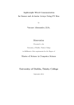
Keyboard
3
2
4
5
1
14
6
7
13
12
11
10
9
8
1. Audio input selectors / Level Controls
8. CUT & TAKE
2. Audio level indicator & Audio monitor
9. T-Bar
3. Menu Controls
10. Main / Sub Source selection buttons
4. Logo & Clock buttons
11. Audio mixer
5. PIP & KEY buttons
12. Headphone socket with volume control
6. Transition Speed
7. Transition Effects
13. Intercom Mic & Headphone Sockets
14. Headphone Socket (Monitor)
8
Keyboard Controls
Audio Input Source Selectors and Level Controls
This section of the HS-2000 controls which audio input channel (CH1~CH4)
will be sent to the Audio Bus and its associated Fader.
This row of audio channel selection buttons has LEDs built in to show which
input channel is active. Level control for each audio input source is via the
rotary pots above each of the audio channel selection buttons.
A+V: When this button is engaged or lit, the audio associated with a selected
video input source automatically follows the video through any transition
between the Main and Sub Sources. When the A+V button is inactive, the
audio sources must be switched manually. For more information, see A+V
(Page 19).
Audio LED Meters
These meters play a vital part in correctly setting the audio levels to avoid
clipping or other distortion.
The LED style Audio meters, show the signal strength at the Audio Output.
The signal they measure is determined by the sources selected by the Audio
Bus selectors and the levels set by the rotary pots and faders.
Audio Monitor Button
Use the Headphone section to monitor any of the sources (CH1, CH 2, CH3,
CH4) or “Master” output. Repeated presses of the Audio Monitor button will
cycle through the monitoring choices. In many cases, headphones may be a
more useful and accurate choice than speakers for audio monitoring.
System Configuration Menu
Press the Menu button in the HS-2000 function section to enter the System
Configuration Menu. Press the up, down, left, and right arrow buttons to
navigate the menu options and to change values. Use the ENT button to
save and confirm any setting that has been amended.
Logo Setting
Press the Logo1, Logo2 or Clock buttons to display the selected function on
the PVW and PGM screens. See Storing New Logos (Page 20)
Logo1 and Logo2 or Logo1 and the Clock can both be selected at the same
time. Logo2 and the Clock cannot be selected/displayed at the same time.
9
PIP / KEY
LUMA PVW and LUMA PGM
A Luma key can be performed between 2 inputs and the result sent to the
PVW (Preview) and PGM (Program) display channels. See Setting up a
LUMA Key (Page 21)
SET
If you want to enable the PIP function, you must first press the SET key, then
press the PIP PVW key and then select the Sub Source button for the PIP
window. The size and position of the window can be set within the System
Configuration Menu. See PIP SETTING (Page 16)
PIP PVW
Allows the user to see what the PIP window will look like and make any
adjustments before the PIP window is taken to the PGM output. Pressing the
PIP PVW button toggles the PIP window on and off using a simple dissolve.
PIP PGM
Once the PIP window is ready to be taken to air the PIP PGM button will
allow a simple dissolve in and out over the top of the current program output.
Transition Speed
Five buttons used to choose different speeds for a transition effect when
using the TAKE button to switch between PVW and PGM sources.
Transition Effects
There are 10 Transition Effects keys. Six of these keys relate to the available
types of WIPE effect. INV (Invert) changes the direction of the chosen WIPE.
SFT changes the softness of the WIPE edge. FRZ freezes the current PGM
image until toggled off or CUT away. MIX is a dissolve effect between the
PVW and PGM sources.
For more information, see Transition Effects (Page 14).
CUT
Forces an immediate switch between the selected main and sub sources.
The selected sub source becomes the main program output with no
transition effect applied.
TAKE
Starts an automated switch between the main and sub sources. The
selected sub source becomes the main program output with the selected
Transition Effect applied at the selected Effect Speed.
10
T-Bar
The T-Bar is used to carry out a manual transition such as a wipe, fade,
mix or key. When it has travelled as far as it can go the transition is
complete.
How to calibrate the T-bar:
1. Turn off the HS-2000 power, and push the T-Bar up as far as it can go to
its Top or AIR position then move the T-Bar back down by 2mm.
2. Press and hold in the SET and SUB SOURCE 1 buttons at the same time.
3. Have a colleague turn on the HS-2000 power. When the SET button and
SUB SOURCE 1 buttons are illuminated yellow release both buttons.
4. Push down the T-Bar as far as it can go to its bottom or PVW position and
then move the T-Bar back up by 2mm. Now press the CUT button.
5. Again push the T-Bar up as far as it can go to its Top or AIR position. Now
press the TAKE button.
6. Press SET button again to end the calibration process.
WARNING: If you do not follow the T-Bar calibrating steps correctly the
T-Bar may work incorrectly
Main Source
Used to select which of the source input channels or backgrounds that are
sent to the Main video PROGRAM output.
Sub Source
Used to select which of the source input channels or backgrounds will be
transitioned to or used as a sub source in an effect such as PIP.
Audio mixer
These CH1~CH4 Audio Level Faders are for controlling the CH1~CH4 audio
mix.
These faders correspond to the Audio Source selector buttons and control
the relative volume of each input in the master output as well as the master
output level. They are called faders because they are used to decrease
(rather than increase) the signal levels to create a balanced and pleasing
mix. When the CH1~CH4 Audio Level Faders are set at -6dB, or Unity, they
pass the audio signal through at the same level as when it entered the bus.
This is why the level setting at the Input Bus is so important.
MASTER
This Slider is for controlling the audio level for the Mixed audio output.
Headphone
Accepts a stereo mini jack plug for stereo headphones. Used with the Audio
Monitor Button. The headphone volume is adjusted by the rotating Head
phone volume control.
Headphone Volume Control
Controls Headphone volume level.
Use the Headphone section to monitor any of the sources ( CH1, CH2,
CH3, CH4 or “Master” ) output.
11
Headphone Socket (Intercom)
¼ “/ 6.3mm Stereo Headphone Socket for conventional headphones.
Plugging in headphones will disable the built-in ITC-50 Intercom speaker
Microphone / Headset Socket (Intercom)
3.5mm Stereo Socket for combined Microphone Headset.
Plugging in a Microphone / Headset will disable the built-in speaker and the
XLR Microphone Input.
Headphone Socket (Monitor)
¼ “/ 6.3mm Stereo Headphone Socket for conventional headphones.
Plugging in headphones will disable the built-in speakers of the monitor.
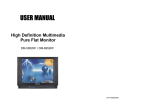
Rear Panel
1. HD- SDI INPUTS 1~3
8. POWER ON / OFF
2. HD- SDI IN or DVI-D IN
9. MONITOR HDMI IN **
3. DVI-D IN
10. AUDIO OUT
4. TALLY Output
11. AUDIO IN
5. 2x HD-SDI PGM OUT
12. TO ITC-100SL BELTPACKS
6. HD-YUV PGM OUT
13. CASE EARTH CONNECTOR
7. DC INPUT 12V 10A
8.
** Note : #9 - The HDMI input is for confidence monitoring only and cannot be mixed
12
Rear Panel Connections
HD- SDI IN
Inputs 1 to 3 are HD-SDI inputs only on BNC
connections.
HD- SDI IN / DVI-D IN
Input 4 has a choice of two connections HD-SDI
(via BNC) or DVI-D.
You select the connection you wish to use - for
more information, see INPUT 4 MODE (Page 17).
DVI-D IN
DVI-I Signal Input (Digital Input 5).
TALLY
Tally out socket. This supplies tally light information
to the Datavideo ITC-50 system (not supplied).
RS-232
9-pin serial port standard RS-232 interface.
Connect PC to update firmware, Logos or Mixer
Configuration.
HD- SDI OUT
4:2:2 SDI Video data supports SMPTE 292M
standard at 1.5G bps.
SDI transfers professional level video signals and
it’s can connect to long distance transmission
systems.
HD- YUV OUT
HD- YUV component analogue output connectors.
DC INPUT
Connect the supplied AC adaptor to this DC Input
socket.
POWER
Switches the power On / Off.
MONITOR HDMI IN
The HS-2000 provides a useful connection for
confidence monitoring of HDMI sources on
location. However, this connection cannot be
mixed. Instead use a DAC-9 to convert the HDMI
source to HD-SDI and then the source can be
mixed via inputs 1~4.
13
AUDIO OUT
Supports XLR Balanced Audio output.
Stereo Mono switch can be used to select a stereo
output or a dual Mono output.
Stereo output will show CH1 & CH3 on XLR A and
CH 2 & CH 4 on XLR B.
Mono output will show the same mono audio
across both XLR outputs A and B.
AUDIO IN
The HS-2000 supports four XLR Balanced Audio
Input channels.
There are two kinds of switches under AUDIO IN:
LINE/MIC switch is used to set the audio as LINE
in or MIC in.
The 48V ON/OFF switch is for phantom power. If
you want to use MIC in, please set the LINE/MIC
switch first, and then if using a Condenser
microphone turn ON the 48V ON/OFF switch. If you
wish to use a Dynamic microphone please turn
OFF the 48V ON/OFF switch.
TO BELTPACK (For Intercom)
Channel Input / Output XLR Sockets
Each of the 5 channels has an XLR connector that
carries bi-directional signals between the ITC-50
and ITC-100SL. All connections are contained
within the one cable.
Main Source and Sub Source Rails
The Main Source Rail shows the active channel, this is the Live output. The active channel will also appear
as the Program Output (PGM). You can immediately switch or CUT from one input channel to another
directly on the Main Source Rail, you will see the PROGRAM Output switch as you press different keys along
this rail. As each key is selected or pressed it will turn Red.
The Sub Source Rail shows the Cued channel, the selected channel will appear in the Preview window. The
selected key will turn Yellow. The Sub Source selection determines which input will be transitioned to when
using any of the transition controls and provides the Sub Source video for Picture in Picture and Key
functions.
14
Transition Effects
1
WIPE from upper Left corner to lower Right corner of screen
2
WIPE from Left to Right of screen
3
WIPE from Top to Bottom of screen
4
WIPE from upper Right corner to lower Left corner of screen
5
WIPE from outside edge of screen to centre of screen
6
WIPE from Left and Right hand sides into the centre of the screen.
7
SFT Controls the border softness of the WIPE or effect.
8
MIX
9
INV Inverts the WIPE direction – the chosen WIPE moves in the opposite direction.
10
FRZ This freezes the PGM video, press it again, and it returns to the selected Live PGM source.
Also known as a fade or dissolve, is a transition where all the pixels of one source are
replaced by all the pixels of another, at a smooth rate, and at the same time.
15
System Configuration Menu
Menu and Navigation
Press the MENU button in the Function section of the HS-2000’s keyboard to enter the System Configuration
Menu. The menu will be displayed on the HS-2000’s Multi Preview output as below.
Press the UP, DOWN, LEFT and RIGHT arrow buttons to highlight or select a menu option. Then use the UP
and DOWN arrow buttons to change the value of the selected item or option. Press the ENT button to Enter
and save your chosen value for the selected menu item.
USER’S PROFILE
- Press the MENU button and highlight the USER’S PROFILE option.
- Press the arrow RIGHT button and select a profile number by using the UP and DOWN arrows.
- Press the ENT button to confirm the chosen profile number to be used.
The current user will also be confirmed between PREVIEW and PROGRAM windows on the Multi
Preview Display.
-
Up to 6 User Profiles can be configured and saved. These profiles are numbered 0 ~ 5.
User’s Profile 0 is also referred to as the BASIC or MASTER USER settings profile.
If there are settings that will be common to all user profiles 1 ~ 5 then they are set here first under
BASIC and then these common settings can be copied to the other user profiles (1 ~ 5) by selecting
LINK TO BASIC. Then while adjusting USER 1 ~ 5, you can refer to the BASIC settings, thus
avoiding multiple and repeated adjustments for all remaining user profiles.
-
Any changes made to the HS-2000’s configuration will be saved to the currently selected profile.
The default user profile at Power On is the last selected profile used.
INPUT SETTINGS
- Press the MENU button and highlight the INPUT SETTINGS option.
- Press the arrow buttons to select an item and press the ENT to confirm the setting.
- BRIGHTNESS: adjustment range from -7 to +7
- CONTRAST: adjustment range from -7 to +7
- SATURATION: adjustment range from -7 to +7
- MASTER USER SETTING: When selected, the values for the above are copied from the BASIC
profile.
16
PIP SETTING
- Press the MENU button and highlight the PIP SETTING.
- Press the arrow buttons to select an item and press the ENT to confirm the setting.
- X- POSITION: adjustment range from 0 to +102 (when MODE SETTING is 1080i)
- Y- POSITION: adjustment range from +113 to 0 (when MODE SETTING is 1080i)
- X- POSITION: adjustment range from 0 to +70 (when MODE SETTING is 720p)
- Y- POSITION: adjustment range from +77 to 0 (when MODE SETTING is 720p)
- SIZE: adjusts the size of the smaller PIP window using a range from +1 to +97
- MASTER USER SETTING: When selected, the values for the above are copied from the BASIC
profile.
If you want to enable the PIP function, you must first press the SET key in the PIP / KEY section of
the HS-2000 keyboard, then press the PIP PVW key and then select the Sub Source channel
required for the PIP window.
The PIP window will appear on the PREVIEW and PROGRAM displays when PIP PVW and PIP
PGM buttons are lit on the HS-2000’s Keyboard.
LUMA SETTING
- Press the MENU button and highlight the LUMA SETTING option.
- Press the arrow buttons to select an item and press the ENT to confirm the setting.
- You can set the value for the LUMA LEVEL (0 Black to 255 White)
- This LUMA LEVEL keys out a grey scale range between 0 and the LUMA LEVEL value set.
- So LUMA LEVEL 20 would key out a range of Black between 0 and 20 from the PGM source.
- MASTER USER SETTING: When selected, the value for the above is copied from the BASIC
profile.
LOGOS
- Press the MENU button and highlight the LOGOS option.
- Press the arrow buttons to select an item and press the ENT to confirm the setting.
- You can select a pre-loaded Logo from the HS-2000’s 14 memory slots for Logo1 and Logo2.
- You can set the on screen positions of Logo1, Logo2 and the Clock.
- X- POSITION: adjustment range from 0 to +114 (under 1080i)
- Y- POSITION: adjustment range from +112 to 0 (under 1080i)
- X- POSITION: adjustment range from 0 to +72 (under 720p)
- Y- POSITION: adjustment range from +150 to 0 (under 720p)
- Accepted Logo sizes 256x192 pixels, 512x96 pixels or 128x384 pixels
- MASTER USER SETTING: When selected, the values for the above are copied from the BASIC
profile.
Logos need to be loaded into the 14 memory slots in preparation before an event – See
Storing New Logos (Page 21).
17
MODE SETTING
- Press the MENU button and highlight the MODE SETTING.
- Press the arrow buttons to select an item and press the ENT to confirm the setting.
- This Mode setting is used to adjust the HD input mode.
- HD Mode values can be 1080/50i - 1080/60i - 1080/59.94i - 720/50p - 720/60p or 720/59.94p
- MASTER USER SETTING: When selected, the values for the above are copied from the BASIC
profile.
-
Please ensure your HD input source(s) match the HD mode of the HS-2000.
The selected HD mode is confirmed between the PREVIEW and PROGRAM windows on the Multi
Preview Display.
MONITOR MODE
- Press the MENU button and highlight the MONITOR MODE option.
- Press the arrow buttons to select an item and press the ENT to confirm the setting.
- This mode adjusts the Multi Preview DVI-D output between 1080i 60Hz and 720p 60Hz.
- MASTER USER SETTING: When selected, the values for the above are copied from the BASIC
profile.
INPUT 4 MODE
- Press the MENU button and highlight the INPUT 4 MODE option.
- Press the arrow buttons to select an input option and press the ENT to confirm the setting.
- This mode is used to switch INPUT 4 from HD-SDI input to DVI-D input and vice versa.
- MASTER USER SETTING: When selected, the values for the above are copied from the BASIC
profile.
The changed setting will also be confirmed between PREVIEW and PROGRAM windows on the
Multi Preview Display.
MASTER USER SETTING
- Press the MENU button and highlight the MASTER USER SETTING option.
- Press the arrow buttons to select an item and press the ENT to confirm the setting.
- This mode is used to return the HS-2000 BASIC profile (USER 0) to its factory default settings.
- If the BASIC profile is changed then any USER profiles (1 ~ 5) linked to BASIC will also be changed.
SOFT EDGE
- Press the MENU button and highlight the SOFT EDGE option.
- Press the arrow buttons to select an item and press the ENT to confirm the setting.
This mode is used to set the size of the soft border (SFT Key) when using a WIPE transition or the
PIP effect.
AUTO TAKE SPEED
- Press the MENU button and highlight the AUTO TAKE SPEED option.
- Press the arrow buttons to select an item and press the ENT to confirm the setting.
- This adjusts the different speeds of the selected transition effect when the TAKE button is used.
18
BACKGROUND
- Press the MENU button and highlight the BACKGROUND option.
- Press the arrow buttons to select an item and press the ENT to confirm the setting.
- This option sets the background colour of the Multi Preview screen – options are Black, Grey or
Blue.
BLACK & BARS POS.RIGHT
- Press the MENU button and highlight the BLACK & BARS POS.RIGHT option.
- Press the arrow buttons to select an item and press the ENT to confirm the setting.
- This option allows the user to change the order of the keys on the Main and Sub Source rails.
- When selected the order of the keys will be BLK, BAR, 1, 2, 3, 4, DVI instead of the original
sequence.
-
Once changed the Key Cap Legends can be carefully removed and relocated to the new position.
FACTORY SETTINGS
- Press the MENU button and highlight the FACTORY SETTINGS option.
- Press the arrow buttons to select an item and press the ENT to confirm the setting.
- This menu option is used when it is required to return the product back to its factory state.
- If you select this option then ALL user settings (BASIC and 1 to 5) are returned to their factory
defaults.
CLOCK SETTINGS
- Press the MENU button and highlight the CLOCK SETTINGS.
- Press the arrow buttons to select an item and press the ENT to confirm the setting.
- This mode is used to set the clock within the HS-2000.
The current Clock value is displayed in between the PREVIEW and PROGRAM windows of the Multi
Preview Display.
MAX BUTTON BRIGHTNESS
- Press the MENU button and highlight the MAX BUTTON BRIGHTNESS option.
- Press the arrow buttons to select an ON or OFF state and press the ENT to confirm the setting.
This menu option is used when the Keyboard button back lights needs to be dimmed or made
brighter.
TWO WAY T-BAR MODE
- Press the MENU button and highlight the TWO WAY T-BAR MODE option.
- Press the arrow buttons to select an ON or OFF state and press the ENT to confirm the setting.
- This menu option is used to change the T-BAR from one way to two way operation or vice versa.
19
Audio Inputs and Levels
Analogue audio comes into the HS-2000 through the XLR connectors on the rear panel (as above diagram).
The HS-2000 supports four XLR Balanced Audio Input channels.
NOTE: Audio cannot be de-embedded by the HS-2000 from a HD-SDI input and Audio will not be
embedded into the HS-2000’s HD-SDI PGM outputs.
There are two kinds of switches next to each XLR input under AUDIO IN: The LINE/MIC switch is used to
set the audio as LINE in or MIC in.
The 48V ON/OFF switch is for Phantom power. If you want to use MIC in, please set the LINE/MIC switch
first, and then if using a Condenser microphone* turn ON the 48V ON/OFF switch. Or if you wish to use a
Dynamic microphone please turn OFF the 48V ON/OFF switch.
*NOTE: Always double check the manual for the microphone being used to see what advice it gives
regarding power as some MICs have internal batteries too.
Audio Outputs
There are two XLR audio output channels A and B. These can act as a stereo pair or as a dual mono output
depending on the stereo mono switch setting. See page 14 also.
A+V Button
The Audio Input Channel Selectors and Level pots are the first
stage in the audio signal path. Each channel carries the audio
associated with a video input channel. When the A+V button is
active, the audio follows the video through a transition. This
means that when this LED is lit, only one channel of the Audio
input section (CH1, CH2, CH3, CH4) can be active at a time.
When the transition is a CUT, the audio will switch over abruptly
at the same time.
Try this: With the A+V button engaged or lit, select Channel 2 on the Main Source bus (of course, you must
have a valid video and audio source connected). Notice that CH2 is lit in the Audio Source section. Now,
select channel 1 on the Sub Source bus. Work the T-Bar to manually perform a transition from CH2 to CH1
and listen for the Audio Input Source channel changing from CH2 to CH1 also.
When the A+V button is not engaged or off, you can manually select which of the 4 Audio input channels will
be applied to the audio out connections. In fact, you have to select one or more of these channels, or there
will be no audio present at the audio out connections.
The A+V button should be inactive while doing level settings at the beginning of a session so that you can
select an input and adjust the initial audio level correctly.
20
HS-2000 Configuration Utility
This Configuration Utility software allows a PC (running Windows XP Professional) to make changes to the
mixer*. A cable needs to be connected between the RS-232 port on the rear of the HS-2000 and the PC
COM1 Serial port.
This software Utility is free and can be downloaded from the following web page
http://www.datavideo.info/en/Mixer%20-%20Switchers/SE-2000
Once downloaded, run the install wizard and follow the on-screen prompts. The software installation will
leave an Icon on the PC desktop as above. With the HS-2000 connected to the PC via an RS-232 cable, the
initial utility screen will be displayed as above, when the program is launched.
Storing New Logos
The Configuration Utility software allows a Windows XP Professional PC to make changes to the Logos
stored within the 14 memory slots of the HS-2000 mixer. This is done from the Logos tab shown below.
New Logos to LOAD and WRITE into these memory slots MUST be 256 x 192 pixels. Your new Logo needs
to be created in a graphics software package first as a TGA 32bit or BMP 24bit file with a clear Alpha
Channel background. The graphics software to create your Logo image is not supplied by Datavideo.
* We recommend that you only use the HS-2000 Configuration Utility to add/write new Logos as changing any
other settings without guidance may cause the mixer or its set up menus to become un-usable.
21
Setting up a Luma Key overlay with Power Point
The HS-2000 has 5 inputs. Input 5 is DVI only and this can be used to connect a DVI-D cable from a
computer’s monitor/graphics card. The PC graphics card will need 2 connections 1 for the PC monitor and a
spare DVI-D connection to go to input 5 on the HS-2000. The PC will need to have Microsoft Office installed
in order for PowerPoint to be used. If all the settings are correct on the mixer and the PC then we can
attempt to use this DVI-D PC display output to create a simple text overlay using the Luma Key function.
1. Connect a DVI-D cable between the HS-2000 and the spare DVI-D port on the PC’s graphics card.
2. Turn on the HS-2000 and then the PC.
3. Create a PowerPoint presentation with White text on a Black background. You may want to create
your own Slide Master within PowerPoint. Use the PowerPoint Help function for advice on how
to do this.
4. Select DVI on the sub source rail of the HS-2000 so it is shown in the PREVIEW window. Check the
Multi Preview Display on the HS-2000, can you see the PC output in the DVI VTR2 or PREVIEW
window?
5. If you cannot see the computer output extend the PC’s desktop within Windows to monitor 2 as
below.
6. PC screen size for monitor 2 should match the HD resolution, for example 1920x1080 or 1280x720.
7. If DVI VTR2 is just a blue screen (blue desktop background only), then try using the PC mouse
pointer to drag a window or a desktop icon across and onto the HS-2000 DVI VTR2 window.
8. OK, so you should now have the Monitor 2 PC display running into input 5 on the HS-2000.
9. Open up Powerpoint on the PC and use Set Up Show so that the presentations play back on Monitor
2 (the HS-2000) and the presentator’s output is sent to Monitor 1 (the PC’s own monitor).
10. Ensure DVI is selected on the HS-2000 Sub Source rail and a video input is chosen on the Main
Source rail.
11. Now that you can see the presentation playing back in the PREVIEW window we can now attempt to
key out the Black parts of the Presentation using the LUMA SETTING option in the HS-2000’s
System Configuration menu whilst the LUMA PVW button is also ON. See LUMA SETTING on page
15 also.
12. Once you have the right LUMA SETTING or overlay effect in the PREVIEW window you can then
press LUMA PGM key to toggle the overlay effect ON or OFF the main PROGRAM output.
22
HD-SDI Cabling Advice
Start with good cabling. BNC coax cables and connectors are not all made to the same standard. From
the thickness and grade of the centre conductor to the type of dielectric, all these factors contribute to
impedance, attenuation and Return Loss (RL). Serial Digital Video coax like Belden 1694A or Canare
L5CFB are good examples of broadcast quality SDI cable.
A 75 Ohm (Ω) impedance must be maintained throughout the HS-2000 SDI signal or cable path, including
BNC connectors etc.
Return Loss is the portion of the transmitted SDI signal that is not admitted to the receiver (mixer) and is
then reflected back along the cable toward the transmitter (DAC-9). Reflections in the transmission path
will cause attenuation as well as distortion of the SDI signal received. The signal is attenuated because
part of it is reflected back and does not make it to the receiver (HS-2000 for example); it is also distorted
because the reflected signal mixes with the original signal causing it to distort as well as adding to the
noise floor.
Care must also be taken with cable length, as it will affect the error rate in the SDI signal. Cable lengths
beyond acceptable limits will see error rates reach a tipping point and this will bring about a total loss of
picture also known as the Cliff Effect. Always check with your supplier for cabling advice on the
maximum distance for a particular signal and data rate, in this case an SDI signal that complies with the
SMPTE 292M standard at 1.5 Gbps. Datavideo Taiwan have determined that single BNC SDI cable
(5CFB) runs of up to 100m should be possible with this unit before the signal would need to be re-clocked
or repeated.
Here is a basic list of other things to avoid
• Do not step on or rest equipment on the cables.
• Do not roll dollies or trolleys over the cables.
• Do not put kinks or sharp bends in the cables.
• Do not exceed the minimum bend radius of the cable.
The general rule for an acceptable bend radius is 10 times the diameter of the cable.
• Cable pulls should be done carefully – do not jerk or stretch the cable(s).
Do not exceed the cable’s maximum pulling tension.
(call the cable supplier / manufacturer for this information.)
• Do not pull cable ties too tight on cable looms.
If you cannot move any cable inside a loom tie, the tie is too tight.
Put an extra piece of cable in when tightening loom ties - then remove it afterwards to create the space.
• Do not put cable management fixings at standard distances apart.
This can lead to deformity at a given wavelength, which can increase RL.
Place your loom cable ties at random distances for the same reason.
23
How to update HS-2000 mixer firmware
From time to time Datavideo may release new firmware to either add new features or to fix reported bugs in
the current mixer firmware. Customers can update the mixer firmware themselves if they wish or they can
contact their local dealer or reseller for assistance should they prefer this method.
This page describes the firmware update process, two programs will be used and it should take
approximately 40 minutes total time to complete.
Once started the update process should not be interrupted in any way as this could result in a nonresponsive mixer.
As well as a working mixer you will need:
The latest Flash Update for the mixer. This can be obtained from your local Datavideo office.
The latest SetUp program for the mixer. See Page 20.
A 9 pin Sub D male to female RS-232 cable. Pin 1 connects to pin 1, pin 2 connects to pin 2, etc.
A Windows XP Professional 32bit PC with a 9pin Sub D COM1 port.
Save the two programs to the PC desktop so you can find them easily.
Stage 1. Run the FlashUpdate_SE2000_xxxx program. (where xxxx represents the version number)
This first part of the update process should take 20 minutes to complete.
Ensure the mixer is switched OFF. Connect the mixer using the sub D 9pin cable between the PC COM1 port
and the mixer’s RS-232 port. Double click the FlashUpdate_SE2000_xxxx application.
Click NEXT then select the option for the COM1 port on the PC and click NEXT.
24
Now turn the mixer ON. Once the application discovers the mixer it will check the firmware on the mixer and
report if it needs updating. Click NEXT to start the update. You will be asked to confirm that you want to
proceed click YES. A progress bar will then be shown as below.
Once complete (100%) the application will ask you to power the mixer OFF and then back ON again. Once
the keyboard lights on the mixer are steady again and the multi Preview image is shown from the mixer
move onto Stage 2 below.
Stage 2. Run the SE2000_SetUp_V2.3 program.
This second part of the update process and should also take 20 minutes to complete.
The mixer will still be connected with the sub D 9pin cable to the PC’s COM1 port. Ensure the mixer is
switched ON. Double click the SE2000_SetUp_V2.3 program and on the first screen click on the reanimate
button.
You will be asked to confirm that you want to proceed click YES. A progress bar will be shown, once finished
(100%) exit the application and power the mixer OFF and then switch it ON.
That is it, the new features or bug fixes should now be in place within the mixer.
25
SE-2000 RS-232 Remote Control Protocol
Communication diagram
Control Interface
Interface
RS232
Baud Rate
115200
Data bits
8
Parity
None
Stop bits
1
Pin Assignment
D-Sub 9pin Female
The pin assignment of the Host Controller and SE-2000 is shown in the following table:
Pin
Host
SE-2000
2
Receive A (RX-)
Transmit A (TX-)
3
Transmit B (TX+)
Receive B (RX+)
5
Common
---
Common
Command Code Format
1
E2
2
E4
3
0F
4
00
13 Bytes(Hex)
5
6
7
8
9
10
11
FF 01 FE 40 02 COM
ARG
COM , ARG : Reference to (Table 3)
12
CRCL
13
CRCH
N-1
CRCL
N
CRCH
Response Code Format
1
E2
2
E4
3
FF
N Bytes(Hex)
4
5
6
7
8
9
…
01 0F 00 FE ERR Len
ERR : C0 (No Error) , other code (have error)
Len : Response data code
26
CRC (CRCL,CRCH)
Check sum! It is transmitted lower byte first.
All the bytes except the last 2 from the block are used to calculate the check sum.
There must be 0x0000 after the check sum calculation including the last 2 bytes,
if the data have been transmitted error free.
The initial value for check sum calculation is 0xFFFF.
The check sum polynomial and examples for the algorithm realization
are given in the “Application Note 27.
Understanding and Using Cyclic Redundancy Checks with
Dallas Semiconductor iButtonTM Products (www.dalsemi.com)”,
in the “CRC-16 computation for ram records in iButtons” section.
CRCL and CRCH can be calculated , particularly, by means of the
tables 1 and 2 according to the rule below:
CRCH’ = Tbl.2 (I),
CRCL’ = Tbl.1 (I) + CRCH, where I = CRCL + InputByte
CRCH and CRCL correspond to higher and lower byte of the current
check sum value, InputByte – next data byte.
CRCH’ and CRCL’ correspond to higher and lower byte of
the new check sum value. Tbl.2 (I) and Tbl.1 (I) correspond to the tables' values,
I is the shift factor in the tables. «+» means bit-wise XOR.
27
unsigned short ComPort_Flag;
unsigned short CMD_Length;
unsigned char CMD_Buf[128];
void Cal_Checksum(void)
{
int i;
unsigned char crc_lo,crc_hi;
unsigned char new_crc_lo,new_crc_hi;
unsigned char temp;
crc_lo=CMD_Buf[CMD_Length-2];
crc_hi=CMD_Buf[CMD_Length-1];
for(i=0;i<(CMD_Length-2);i++)
{
temp=crc_lo^CMD_Buf[i];
new_crc_hi=CRC16_TABLE_HI(temp); // Reference to Table 1
new_crc_lo=CRC16_TABLE_LO(temp)^crc_hi; // Reference to Table 2
crc_lo=new_crc_lo;
crc_hi=new_crc_hi;
}
CMD_Buf[CMD_Length-2]=crc_lo;
CMD_Buf[CMD_Length-1]=crc_hi;
}
void MainSource1()
{
// TODO: Add your control notification handler code here
CMD_Length=13;
CMD_Buf[0]=0xE2;
CMD_Buf[1]=0xE4;
CMD_Buf[2]=0x0F;
CMD_Buf[3]=0x00;
CMD_Buf[4]=0xFF;
CMD_Buf[5]=0x01;
CMD_Buf[6]=0xFE;
CMD_Buf[7]=0x40;
CMD_Buf[8]=0x02;
CMD_Buf[9]=0x03; // COM
CMD_Buf[10]=0x00; // ARG
CMD_Buf[11]=0xFF; // CRCL
CMD_Buf[12]=0xFF; // CRCH
Cal_Checksum();
SendCommand();
}
Execute MainSource1() of result :
CMD_Buf[0~12] = E2, E4, 0F, 00, FF, 01, FE, 40, 02, 03, 00, CD, 16
Other example :
Main Source 2 = E2, E4, 0F, 00, FF, 01, FE, 40, 02, 03, 01, 0C, D6
Speed 1 : = E2, E4, 0F, 00, FF, 01, FE, 40, 02, 20, 00, D4, 26
Mix : = E2, E4, 0F, 00, FF, 01, FE, 40, 02, 32, 00, D8, 86
28
Table 1. Lower CRC byte calculation coefficients.(Hex)
000h 0c1h 081h 040h 001h 0c0h 080h 041h
001h 0c0h 080h 041h 000h 0c1h 081h 040h
001h 0c0h 080h 041h 000h 0c1h 081h 040h
000h 0c1h 081h 040h 001h 0c0h 080h 041h
001h 0c0h 080h 041h 000h 0c1h 081h 040h
000h 0c1h 081h 040h 001h 0c0h 080h 041h
000h 0c1h 081h 040h 001h 0c0h 080h 041h
001h 0c0h 080h 041h 000h 0c1h 081h 040h
001h 0c0h 080h 041h 000h 0c1h 081h 040h
000h 0c1h 081h 040h 001h 0c0h 080h 041h
000h 0c1h 081h 040h 001h 0c0h 080h 041h
001h 0c0h 080h 041h 000h 0c1h 081h 040h
000h 0c1h 081h 040h 001h 0c0h 080h 041h
001h 0c0h 080h 041h 000h 0c1h 081h 040h
001h 0c0h 080h 041h 000h 0c1h 081h 040h
000h 0c1h 081h 040h 001h 0c0h 080h 041h
001h 0c0h 080h 041h 000h 0c1h 081h 040h
000h 0c1h 081h 040h 001h 0c0h 080h 041h
000h 0c1h 081h 040h 001h 0c0h 080h 041h
001h 0c0h 080h 041h 000h 0c1h 081h 040h
000h 0c1h 081h 040h 001h 0c0h 080h 041h
001h 0c0h 080h 041h 000h 0c1h 081h 040h
001h 0c0h 080h 041h 000h 0c1h 081h 040h
000h 0c1h 081h 040h 001h 0c0h 080h 041h
000h 0c1h 081h 040h 001h 0c0h 080h 041h
001h 0c0h 080h 041h 000h 0c1h 081h 040h
001h 0c0h 080h 041h 000h 0c1h 081h 040h
000h 0c1h 081h 040h 001h 0c0h 080h 041h
001h 0c0h 080h 041h 000h 0c1h 081h 040h
000h 0c1h 081h 040h 001h 0c0h 080h 041h
000h 0c1h 081h 040h 001h 0c0h 080h 041h
001h 0c0h 080h 041h 000h 0c1h 081h 040h
29
Table 2. Higher CRC byte calculation coefficients.(Hex)
000h 0c0h 0c1h 001h 0c3h 003h 002h 0c2h
0c6h 006h 007h 0c7h 005h 0c5h 0c4h 004h
0cch 00ch 00dh 0cdh 00fh 0cfh 0ceh 00eh
00ah 0cah 0cbh 00bh 0c9h 009h 008h 0c8h
0d8h 018h 019h 0d9h 01bh 0dbh 0dah 01ah
01eh 0deh 0dfh 01fh 0ddh 01dh 01ch 0dch
014h 0d4h 0d5h 015h 0d7h 017h 016h 0d6h
0d2h 012h 013h 0d3h 011h 0d1h 0d0h 010h
0f0h 030h 031h 0f1h 033h 0f3h 0f2h 032h
036h 0f6h 0f7h 037h 0f5h 035h 034h 0f4h
03ch 0fch 0fdh 03dh 0ffh 03fh 03eh 0feh
0fah 03ah 03bh 0fbh 039h 0f9h 0f8h 038h
028h 0e8h 0e9h 029h 0ebh 02bh 02ah 0eah
0eeh 02eh 02fh 0efh 02dh 0edh 0ech 02ch
0e4h 024h 025h 0e5h 027h 0e7h 0e6h 026h
022h 0e2h 0e3h 023h 0e1h 021h 020h 0e0h
0a0h 060h 061h 0a1h 063h 0a3h 0a2h 062h
066h 0a6h 0a7h 067h 0a5h 065h 064h 0a4h
06ch 0ach 0adh 06dh 0afh 06fh 06eh 0aeh
0aah 06ah 06bh 0abh 069h 0a9h 0a8h 068h
078h 0b8h 0b9h 079h 0bbh 07bh 07ah 0bah
0beh 07eh 07fh 0bfh 07dh 0bdh 0bch 07ch
0b4h 074h 075h 0b5h 077h 0b7h 0b6h 076h
072h 0b2h 0b3h 073h 0b1h 071h 070h 0b0h
050h 090h 091h 051h 093h 053h 052h 092h
096h 056h 057h 097h 055h 095h 094h 054h
09ch 05ch 05dh 09dh 05fh 09fh 09eh 05eh
05ah 09ah 09bh 05bh 099h 059h 058h 098h
088h 048h 049h 089h 04bh 08bh 08ah 04ah
04eh 08eh 08fh 04fh 08dh 04dh 04ch 08ch
044h 084h 085h 045h 087h 047h 046h 086h
082h 042h 043h 083h 041h 081h 080h 040h
30
Table 3. Command Type
No.
1
COM (Hex)
ARG (Hex)
00
00
01
02
03
04
Description
Sub source: Set SDI input port 1
Sub source: Set SDI input port 2
Sub source: Set SDI input port 3
Sub source: Set SDI input port 4
Sub source: Set SDI input port 5
2
01
00
Sub source: Set Black Screen
3
02
00
Sub source: Set Colour Bar
4
03
00
01
02
03
04
Main source: Set SDI input port 1
Main source: Set SDI input port 2
Main source: Set SDI input port 3
Main source: Set SDI input port 4
Main source: Set SDI input port 5
5
04
00
Main source: Set Black Screen
6
05
00
Main source: Set Colour Bar
7
10
00
01
Logo 1 turn off
Logo 1 turn on
8
11
00
01
02
Logo 2 and Clock turn off
Logo 2 turn on
Clock turn on
9
20
00
01
02
03
04
Auto function :
Auto function :
Auto function :
Auto function :
Auto function :
10
30
00
01
02
03
04
05
08
09
0A
0B
0C
0D
Wipe Effect Type 1
Wipe Effect Type 2
Wipe Effect Type 3
Wipe Effect Type 4
Wipe Effect Type 5
Wipe Effect Type 6
Wipe Effect Type 1 of
Wipe Effect Type 2 of
Wipe Effect Type 3 of
Wipe Effect Type 4 of
Wipe Effect Type 5 of
Wipe Effect Type 6 of
Set Speed as level 1
Set Speed as level 2
Set Speed as level 3
Set Speed as level 4
Set Speed as level 5
11
31
00
01
Effect hard border
Effect soft border
12
32
00
01
Mix function
Wipe function
13
40
00
Cut function
14
41
00
Auto function
31
Inversion
Inversion
Inversion
Inversion
Inversion
Inversion
15
50
00
01
02
03
04
PIP source: Set SDI input port 1
PIP source: Set SDI input port 2
PIP source: Set SDI input port 3
PIP source: Set SDI input port 4
PIP source: Set SDI input port 5
16
51
00
01
PIP display on Sub source
PIP turn off on Sub source
17
52
00
01
PIP display on Main source
PIP turn off on Main source
18
61
00
01
Luma disable on Sub source
Luma enable on Sub source
19
62
00
01
Luma disable on Main source
Luma enable on Main source
20
70
00
01
Frame Freeze turn off
Frame Freeze turn on
21
80
00
System time read
22
81
System time of Hour adjustment
23
82
24
83
25
90
Hours
(BCD)
Minutes
(BCD)
Second
(BCD)
00
System time of Minute adjustment
System time of Second adjustment
Get device status
Table 4. Response Code
No.1~20, 22, 23, 24
Byte 1
2
3
4 5
6 7
8
9 10 11
Data E2 E3 FF 01 0F 00 FE C0 00 BE C0
No.21
Byte 1
2
3
4 5
6 7
8
9 10
Data E2 E4 FF 01 0F 00 FE C0 03 18
11 12
22 05
13
68
14
C4
Byte 9 : Len =03
Bytes 10,11&12 : System Time = 18:22:05
No.25
Byte 1
2
3
4 5
6 7
8
9 10
Data E2 E4 FF 01 0F 00 FE C0 29 Table5
32
11
CRCL
12
CRCH
Table 5. Status Code (41 Bytes , reference to page 34 & 35)
Byte 1:
Byte 2:
Byte 3:
Byte 4:
Current_User_Number Input A
Input B
PIP_Input
Byte 5:
Byte 6:
Byte 7:
Byte 8:
Effect
Speed
Speed_Value_0
Speed_Value_1
Byte 9:
Byte 10:
Byte 11:
Byte 12:
Speed_Value_2
Speed_Value_3
Speed_Value_4
Mux_Line_A
Byte 13:
Byte 14:
Byte 15:
Byte 16:
Mux_Line_B
Bright_Cur
Contrast_Cur
Saturation_Cur
Byte 17:
Byte 18:
Byte 19:
Byte 20:
X_Lbl_1
Y_Lbl_1
X_Lbl_2
Y_Lbl_2
Byte 21:
Byte 22:
Byte 23:
Byte 24:
Lbl_1_Number
Lbl_2_Number
X_clock
Y_clock
Byte 25:
Byte 26:
Byte 27:
Byte 28:
Background_Number
Brightness_Control
Color_Fill
X_PIP
Byte 29:
Byte 30:
Byte 31:
Byte 32:
Y_PIP
PIP_Size
Luma_Key_Level
Sys_Format
Byte 33:
Byte 34:
Byte 35:
Byte 36:
Inp_3_Mode
Link_Flags
Link_Flags_Ext
Flags_Mixer
Byte 37:
Byte 38:
Byte 39:
Byte 40:
Flags_Line_A
Flags_Line_B
Flags_Sources_Position Flags_DSK
Byte 41:
Flags_Lbl
33
Current_User_Number – current user number (0…5), number 0 corresponds to the Master User which
other the other users settings and adjustments can be linked to.
Input_A, Input_B, PiP_Input – input number currently switched to the multiplexor’s Line A, multiplexor’s
Line B and PiP shaper input;
Effect – currently set transition effect (curtains):
r FB B1 B0 E3 E2 E1 E0
r- reserved bit,
FB- soft border activation flag(0 – off, 1 – on),
B1, B0- effect border width, 0… 3,
E3 – effect inversion flag(0 – direct, 1 – inverse),
E2, E1, E0- effect number(0… 5);
Speed – number of the pressed key for speed selection (0… 4);
Speed_Value_0, Speed_Value_1, Speed_Value_2, Speed_Value_3, Speed_Value_4 – predefined speed
corresponding to the keys for Speed Selection (4… 64);
Mux_Line_A, Mux_Line_B – the multiplexor’s Line A and Line B status:
r r r r r M2 M1 M0
r- reserved bits,
M2, M1, M0 – signal source for the Line(000- selected input (Input_A or Input_B), 001- reserved,
010- Color Bars, 011- Color Fill defined by Color_Fill parameter);
Bright_Cur – brightness of the last selected source (0x48… 0xb8 with step 8);
Contrast_Cur – contrast of the last selected source (0x24… 0x5c with step 4);
Saturation_Cur – color saturation of the last selected source (0x24… 0x5c with step 4);
X_Lbl_1, X_Lbl_2, X_clock – X-coordinate for Logo 1 or Logo 2 or Clock (0… 62 for 1280x720 screen
resolution or 0… 102 for 1920x1080 screen resolution);
Y_Lbl_1, Y_Lbl_2, Y_clock – Y-coordinate for Logo 1 or Logo 2 or Clock (0… 130 for 1280x720 screen
resolution or 0… 110 for 1920x1080 screen resolution);
Lbl_1_Number – Logo 1 number (0… 13);
Lbl_2_Number – Logo 2 number (0…13);
Background_Number – multiscreen background image number(0…7);
Brightness_Control – keyboard LED brightness factor(0… 1);
Color_Fill – Color Fill number(0… 7);
X_PiP – X-coordinate for PiP (0… 70 for 1280x720 screen resolution or 0… 102 for 1920x1080 screen
resolution);
Y_PiP – Y-coordinate for PiP (0… 77 for 1280x720 screen resolution or 0… 113 for 1920x1080 screen
resolution);
PiP_Size – PiP size(32… 64);
Luma_Key_Level – Luma Key threshold level(0…255);
Sys_Format – multiscreen resolution (the higher 4 bits) and the output signal system (the lower 4 bits). The
following values are valid:
Mon_1920x1080_i60
Out_1920x1080_i25
Mon_1920x1080_i60
Out_1920x1080_i30
Mon_1920x1080_i60
Out_1920x1080_i29.95
Mon_1920x1080_i60
Out_1280x720_p50
Mon_1920x1080_i60
Out_1280x720_p60
Mon_1920x1080_i60
Out_1280x720_p59.9
Mon_1280x720_p60
Out_1920x1080_i25
Mon_1280x720_p60
Out_1920x1080_i30
Mon_1280x720_p60
Out_1920x1080_i29.95
Mon_1280x720_p60
Out_1280x720_p50
Mon_1280x720_p60
Out_1280x720_p60
Mon_1280x720_p60
Out_1280x720_p59.9
Mon_1920x1080_i60
Mon_1280x720_p60
=0
=1
Out_1920x1080_i25
Out_1920x1080_i30
Out_1920x1080_i29.95
Out_1280x720_p50
Out_1280x720_p60
Out_1280x720_p59.9
34
=0
=1
=2
=3
=4
=5
Inp_3_Mode – the current input 3 mode, 0 – SDI, 1 – DVI;
Link_Flags – Master user settings link flags, it may be unlinked(value 0) or linked(value1) to the
corresponding basic parameter:
bit 7 – input 0 settings link flag (brightness, contrast, saturation),
bit 6 – input 1 settings link flag (brightness, contrast, saturation),
bit 5 – input 2 settings link flag (brightness, contrast, saturation),
bit 4 – input 3 settings link flag (brightness, contrast, saturation),
bit 3 – input 4 settings link flag (brightness, contrast, saturation),
bit 2 – position and numbers of the Logo 1, Logo 2 and Clock position link flag,
bit 1 – PiP position and size link flag,
bit 0 – input 3 mode link flag;
Link_Flags_Ext – Master User settings extended flags, it may be unlinked (value 0) or linked (value 1) to the
corresponding basic parameter:
bit 7 – output signal system link flag,
bit 6 – multiscreen resolution link flag,
bit 5 – Luma Key threshold level link flag,
bits 4… 0 reserved, ignore;
Flags_Mixer – switching flags (mixing):
bit 7 – Line connected to Program output (Main Source), 0 – Line A, 1 – Line B,
bit 6 – reserved, ignore,
bit 5 – reserved, ignore,
bit 4 – switch mode, 0 – mixing, 1 – curtains,
bits 3… 0 reserved, ignore;
Flags_Line_A, Flags_Line_B – Frame freeze flags of Line A and Line B:
bit 7 – 0 - Frame freeze off, 1 - Frame freeze on
bits 6… 0 – reserved, ignore;
Flags_Sources_Position – Selection Key inversion flags and switcher’s T-bar mode flag:
bit 7 – 0 – keyboard’s source Selection Keys are arranged in direct manner (Source 1 is on the left),
1 – inverse manner (Bar is on the left),
bit 6 – 0 – T-bar is active only while moving upwards, 1 – T-bar is active while moving both upwards
and downwards,
bits 5… 0 reserved, ignore;
Flags_DSK – PiP and Luma Key out flags:
bit 7… 6 – reserved, ignore,
bit 5 – 1 – Luma Key is output onto Preview channel, 0 – not,
bit 4 – 1 – Luma Key is output onto Program channel, 0 – not,
bit 3 – 1 – PiP is output onto Preview channel, 0 – not,
bit 2 – 1 – PiP is output onto Program channel, 0 – not,
bits 1… 0 – reserved, ignore;
Flags_Lbl – Logo and Clock activation flags:
bit 7 – 1 – Logo 1 is output onto Program channel, 0 – not,
bit 6 – 1 – Logo 2 is output onto Program channel, 0 – not,
bit 5 – 1 – Logo 1 is output onto Preview channel, 0 – not,
bit 4 – 1 – Logo 2 is output onto Preview channel, 0 – not,
bit 3 – Clock activation instead of Logo 2 (0- Logo 2, 1- Clock),
bits 2… 0 – reserved, ignore;
1.26. COM = 0xA0 – copy and write setting parameters Common_Settings (Section 2) from the device’s
EEPROM into the device’s volatile memory. ARG = 0. Device replies with LEN = 0, ANSW is not available.
1.27. COM = 0xA0 – device soft reset. ARG = 0. Device replies with LEN = 0, ANSW is not available. The
device executes soft reset and it completely reboots (similar to the power recycle). It is impossible to
establish a connection with the device for around 8 seconds.
35
Intercom & Monitor Control Panel
1
2
3
4
5
ITC-50 Intercom Controls
6
7
8
9
Monitor Controls
1. XLR Microphone Socket
6. Source Select
2. MUTE Button
7. Aspect Ratio & PIP Button
3. 1~5 & ALL Channel Buttons
8. Menu Navigation Buttons
4. Volume Control
5. Built-In Speaker
9. Volume Control & Audio
Meter
ITC-50 Intercom Controls
XLR Microphone Socket
Combined XLR / ¼” (6.3mm) Jack Microphone Input for either a Condenser or
Dynamic Gooseneck Microphone. XLR supports Condenser Microphones ¼”
(6.3mm) Jack supports Dynamic.
MUTE Button
Mutes all communication from the base station or any channel.
N.B. If any channel uses the CALL button the paging tone will still sound
even when the MUTE button is active.
Channel Buttons 1~5
Opens communication with individual channels. More than 1 channel can be
active at any given time, active channels are illuminated red.
All active channels will hear any communication from the operator or from any
other active channel.
The buttons will also indicate if any channel is paging, the paging channel will
flash in orange until the page is answered.
ALL Button
Opens communication with all channels. All channels will hear communication
from the operator, or from any other channel using the TALK button.
Volume Control
Controls the Volume of the built-in speaker or outputs to the headphones or
mic/headset according to what is connected
Built-In Speaker
Sounds audible alert when a channel is paging and provides audio during
talkback conversations. Speaker is mute when headphones or mic / headset are
connected to the ITC-50
36
Monitor Controls
Source Select Buttons
Select the type of input you are using - HDMI, PREVIEW, PROGRAM
The active input will be indicated by a red LED on the Source Button
Aspect Ratio Button
Sets the Aspect Ratio to 16:9 / 4:3
PIP Button
Activates Picture in Picture Mode - See PIP Menu for more details. Red LED will
light when PIP mode is active.
Menu Navigation Buttons
Display and navigate the set up menus - See Menu Options for more details
Down Button also switches the Safe Area Mask On / Off
UP Button also switches the 4:3 Mask On / Off - (only available in 16:10 modes)
Mute Button
Mutes the audio from the internal speakers or headphone socket.
Volume Control & Audio Meter
Adjusts the monitor speakers / headphone volume up / down.
Monitor Menu Options
The TLM-170 is set up via on screen menus. To display the on screen menu press the MENU button.
The menus are navigated using the Up / Down buttons.
There are four menus
Colour Processor
37
PIP Feature Setting
Special Feature Setting
System Information
Colour Processor
The first menu to be displayed is the Colour Processor Menu.
To access the Colour Processor Menu press enter, the Brightness setting will be highlighted.
38
To adjust the Brightness press Enter again. An adjustment bar will appear at the bottom of the screen.
Use the Up / Down buttons to change the setting and then press Enter to store the new value and return to
the main menu.
To select a different setting (Contrast, Saturation, Sharpness) use the Up / Down buttons. Follow the same
procedure to set the other values.
HS-2000 Monitor PIP Menu
The HS-2000 Monitor PIP Menu allows you to adjust the appearance of the picture in picture on the HS-2000
monitor only.
Please see pages 9 and 16 of this manual if you wish to use a PIP effect within your HS-2000 mixed
PGM output.
The position, size, main source and sub source can be set in the monitor menus.
To access the monitor menu press menu and then the enter so that PIP Mode is highlighted
To access the options for the selected setting press enter again, so that the option column is highlighted - In
this case Large PIP.
39
Use the Up / Down buttons to navigate the available options.
You can choose:
You can also choose:
PIP Mode
Large PIP
Small PIP
PIP Position
Bottom-Right
Top-Left
Top-Right
Bottom Left
PIP Main Source
COMP. - Component
HDMI
SDI
PIP Sub Source
COMP. - Component
HDMI
SDI
N.B. The PIP feature can only be one analogue source and one digital source. i.e. If the main source
is analogue (COMP.) then the sub source must be digital(SDI / HDMI), and vice versa.
Examples:
Main Source
Sub Source
= COMP.
= SDI / HDMI
Main Source
Sub Source
= HDMI / SDI
= COMP.
Special Feature Menu
The Special Feature Menu has settings for the safe area frame, the scan mode and the speaker settings.
The menu is accessed in the same way as the other menus, press the ENTER button and then use the UP /
DOWN buttons to highlight the setting you want to alter. In this case Frame Ratio
40
Once the setting is highlighted press the ENTER button again to highlight the options, and then use the UP /
DOWN buttons to select the required value, and press ENTER once more to accept the new value.
In the Special Feature Menu you can choose:
Frame Ratio - This will display a “Safe Area”
frame on the screen
70%
Off / 70% / 80% / 90%
80%
90%
Once you have set the Frame Ratio you can exit the menu. To display the Safe Area frame press the DOWN
Button
Mask Type - This sets the 4:3 Mask option.
Overlay / Transparent
Overlay Mode
Transparent Mode
Once you have set the Mask Type you can exit the menu. To display the 4:3 Mask press the UP Button
N.B. Only works in 16:9 mode
Scan Mode
Overscan / Underscan
Internal Speaker
Mute Control - On / Off
External Speaker
Mute Control - On / Off
41
System Information Menu
The System Information Menu displays the Firmware Version of the monitor, and offers a Factory Reset
option, which will return all the settings of the monitor to the factory defaults.
To reset the monitor press the ENTER button, then press the up/down button so that Factory Reset is
highlighted, and then press ENTER again to highlight the options column.
Use the UP / Down button to select Yes from the options and then press ENTER to reset the monitor. After a
few seconds the monitor will be reset.
This page also offers the ability to change the HDMI format between YUV and RGB.
This page also offers 4 settings for Colour Temperature. The default is 6500K but this can be changed to
7500K, 9300K or a USER defined setting based on Red, Green and Blue values.
42
ITC-100SL Slave Unit
XLR Connection
Connects the ITC-100SL to the ITC-50 Base Station. Power, tally and bi-directional audio
are all carried through the same cable.
Call Button
Sends a paging message to the ITC-50 Base Station. The channel button will flash orange
and there will be an audible tone, each time the button is pressed.
Bi-Colour Tally LED
Will illuminate RED when the channel is LIVE and AMBER when the channel is CUED
Talk Button
Opens up talk back communication with the ITC-50 base station, and any other active
channels. Press the button to talk; release the button to end communication.
PLEASE NOTE: It is important to release the talk button to deactivate the talk
channel as soon as you have finished talking, otherwise it will
become distracting and confusing for other members of the crew.
Volume Control
Adjusts the volume of the headphones.
43
Mic / Headphone Socket
The ITC-100SL has both 3.5mm and 2.5mm Mic / Headset socket. A standard 3.5mm Mic /
Headset can be used, or a Motorola type 2.5mm Mic / headset could be used if preferred.
External Tally LED Socket
An external tally display (TD-1) can be connected to the ITC-100SL. This enables the tally
light to be positioned in a more convenient place, such as on top of the camera. When the
channel is LIVE the LED will be RED, and when the channel is CUED the LED will be
AMBER.
N.B. The Tally LED on the ITC-100SL will continue to operate as normal when a TD-1
has been added.
Power LED
The Power LED indicates when the channel is active. If the operator has opened the
channel by pressing the channel button 1 ~ 8, or by pressing ALL then the LED will light
up.
N.B. The tally indicator lights will continue to work even when the Power LED is not
on, and the channel is not active.
Optional Datavideo Accessory Items for the HS-2000
Datavideo have a number of accessory products which will allow you to get the most from your new HS-2000.
Please speak to your local dealer or visit the website for your local Datavideo office for more details on these
and other products.
HRS-10HD
Integrated SD & HD-SDI field
recording and monitoring solution.
TLM-700HD
7” HD-SDI /HDMI /HD YUV monitor
Battery or Mains powered
Audio Delay Box
AD-100
DAC-9
Tripod mounted
HDMI to HD-SDI converter
44
HS-2000 (SE-2000) Specification
Inputs
Outputs
Video Input
• 4x BNC connector for HD -SDI input
• 2x DVI connector for DVI-D input (1x DVI-D input is collective with SDI#4 channel)
• 2x HD-SDI output, 1x HD-YUV output
• Video delay through the mixer 1 Frame or less
• Audio delay through the mixer less than 1 Frame
• HD (1080/50i - 1080/60i - 1080/59.94i - 720/50p - 720/60p - 720/59.94p)
Other Interface
• Serial (Editor) D-Sub 9 Pin x 1 RS232
• Tally Output D-Sub 15 Pin x 1 14 Channel Open Collector Output
• 4 x XLR balance audio input separate channel, 2 x XLR balance audio output.
• Support Line and MIC mode
HD SDI signal
SMPTE 292M standard complied with
• Output return loss : More than 15 dB (5MHz to 750MHz)
More than 10 dB (750MHz to 1.5 GHz)
• Output level : 0.8 Vpp ± 10%
• Rise time : Less than 270 ps
• Fall time : Less than 270 ps
• Difference between rise time and fall time within 100 ps
• Alignment jitter : Less than 0.2 UI
• Timing jitter : Less than 1.0 UI
• Eye aperture ratio : More than 90%
• DC offset : 0 ± 0.5V
• Equalizer use 5C-FB cable support 100 meters
HD-YUV Output
Audio
Audio Mixer
IRE
Operating
Temperature
Humidity
Dimension & Weight
Power
• Bandwidth 30MHz < +/- 3dB
• S/N Ratio > 50 dB
• DG <3 degree, DP <3% ( Base on U, V signal analyze)
• Bandwidth 20~20KHz < +/- 3dB
• S/N Ratio > 70 dB
• THD. < 0.1%
• 4 Channel audio input mixer (balanced audio)
• Line mode/MIC mode selectable
• 2 Channel audio output, balanced audio
• 0 - 7.5 IRE Options (NTSC Only)
• 0°C to 40°C (32°F to 102°F)
• 10% to 90% (non condensing)
• 500mm (W) x 520mm (D) x 165mm (H) / 17 Kg
• Input 100 ~ 240V AC 50Hz / 60Hz 2.5A
45
ITC-50 Specification
INPUTSN
&
OUTPUTS
MIC / HEADSET
3.5mm Stereo Jack Socket for combination Headphone / Microphone
Headset Impedance 8~600 ohms 100mW(min)
HEADPHONE
¼” (6.3mm) Stereo Headphone Socket
Headset Impedance 8~600 ohms 100mW(min)
MICROPHONE
3 Pin XLR / ¼” (6.3mm) Jack Microphone Socket Switchable Condenser /
Dynamic Input.
Microphone Level -67dB
FREQUENCY RESPONSE
550-3.6KHz, < +/-3dB
THD
< 3%
S/N
> 50dB
BUILT-IN SPEAKER
70mm x 30mm 32 Ohm 3 Watts
ITC-100SL Specification
INPUT
5 Pin XLR Connector
MIC / HEADSET SOCKET
3.5mm Stereo Jack Socket for combination Headphone / Microphone
Headset Impedance 8~600 ohms 100mW(min)
Microphone Level -67Db or 2.5mm Stereo Jack Socket, for Motorola
Mobile Phone type headset / microphone
TALLY OUT SOCKET
3.5mm Jack Socket to connect to TD-1 Tally Indicator
TALLY LED
Bi-Colour LED – RED indicates LIVE / AMBER Indicates CUED
POWER LED
Illuminates to indicate that power is being received
Monitor Specification
LCD
Resolution
1600 x 900
Aspect Ratio
16:10 / 4:3
Viewing Angle 45°/ 45°(L/R)Horizontal , 25°/45°(U/D) Vertical
Response Time 8ms (B to W)
Contrast
600:1
Brightness
200 cd/m2
Backlight
LED
Audio Outputs
Terminal Connection for speaker outputs (2 Watt)
Maximum output for speaker in FP is 2 Watts
Headphone Socket 3.5mm Stereo Jack
Video Adjustments
Brightness
0 ~ 100
Contrast
0 ~ 100
Colour
0 ~ 100
Tint (NTSC)
0 ~ 100
Sharpness
0 ~ 24
46
Service & Support
It is our goal to make your products ownership a satisfying experience. Our support staff
are available to assist you in setting up and operating your system. Please refer to our web
site www.datavideo-tek.com for answers to common questions, support requests or
contact your local office below.
Datavideo Global Website: www.datavideo-tek.com
Datavideo Corporation
Tel: +1 562 696 2324
Fax: +1 562-698-6930
E-Mail: [email protected]
Datavideo Technologies Europe BV
Tel: +31-30-261-96-56 Fax: +31-30 261-96-57
E-Mail: [email protected]
Datavideo UK Limited
Tel: +44 1457 851 000
E-Mail: [email protected]
Fax: +44 1457 850 964
Datavideo Technologies Co., Ltd
Tel: +886 2 8227 2888 Fax: +886-2-8227-2777
E-mail: [email protected]
Datavideo Technologies China Co., Ltd
Tel: +86 21-5603 6599 Fax:+86 21-5603 6770
E-mail: [email protected]
Datavideo Technologies (S) PTE LTD
Tel: +65-6749 6866
Fax: +65-6749 3266
E-mail: [email protected]
Datavideo HK Ltd
Tel: +852 2833 1981
E-mail: [email protected]
Fax: +852-2833-9916
All the trademarks are the properties of their respective owners.
Datavideo Technologies Co., Ltd. All rights reserved 2011
P/N: G082060500E7
47