1
Installation and User's Guide
REFERENCE
86 A1 95ET 00
NOVASCALE
R422
NOVASCALE
R422
Installation and User's Guide
Hardware
July 2007
BULL CEDOC
357 AVENUE PATTON
B.P.20845
49008 ANGERS CEDEX 01
FRANCE
REFERENCE
86 A1 95ET 00
The following copyright notice protects this book under Copyright laws which prohibit such actions as, but not limited
to, copying, distributing, modifying, and making derivative works.
Copyright
Bull SAS 2007
Printed in France
Suggestions and criticisms concerning the form, content, and presentation of this
book are invited. A form is provided at the end of this book for this purpose.
To order additional copies of this book or other Bull Technical Publications, you
are invited to use the Ordering Form also provided at the end of this book.
Trademarks and Acknowledgements
We acknowledge the right of proprietors of trademarks mentioned in this book.
Intel® and Xeon® are registered trademarks of Intel Corporation.
Windows® Compute Cluster Server 2003 and Microsoft® software are registered trademarks of Microsoft
Corporation.
UNIX® is a registered trademark in the United States of America and other countries licensed exclusively through
theOpen Group.
Linux® is a registered trademark of Linus Torvalds.
Supermicro® is a registered trademark of Supermicro Computer Limited.
Phoenix® is a registered trademark of Phoenix Technologies Ltd.
Novascale® Universal is a registered trademark of Bull S.A.S.
The information in this document is subject to change without notice. Bull will not be liable for errors
contained herein, or for incidental or consequential damages in connection with the use of this material.
Preface
About This Manual
This manual is written for professional system integrators and PC technicians. It provides
information for the installation and use of the NovaScale R422/R422-INF servers.
Installation and maintenance should be performed by experienced technicians only.
NovaScale R422/R422-INF servers are 1U Twin (two server boards in a 1U chassis)
rackmount servers based in the NovaScale R422/R422-INF box (CSE-808T-980B) and two
(twin) X7DBT or two X7DBT-INF server boards. The NovaScale R422 X7DBT/X7DBT-INF
server boards support dual Intel® 5300/5100 Series processors.
Manual Organization
Chapter 1: Introduction
The first chapter provides a checklist of the main components included with the server
system and describes the main features of the Super NovaScale R422 X7DBT/X7DBT-INF
serverboard and the NovaScale R422/R422-INF box (CSE-808T-980B).
Chapter 2: Server Installation
This chapter describes the steps necessary to install the NovaScale R422/R422-INF server
into a rack and check out the server configuration prior to powering up the system. If your
server was ordered without the processor and memory components, this chapter will refer
you to the appropriate sections of this manual for their installation.
Chapter 3: System Interface
Refer to this chapter for details on the system interface, which includes the functions and
information provided by the control panel on the chassis as well as other LEDs located
throughout the system.
Chapter 4: System Safety
You should thoroughly familiarize yourself with this chapter for a general overview of safety
precautions that should be followed when installing and servicing the NovaScale R422/
R422-INF server.
Chapter 5: Advanced Serverboard Setup
Chapter 5 provides detailed information on the NovaScale R422 X7DBT/X7DBT-INF server
boards, including the locations and functions of connectors, headers and jumpers. Refer to
this chapter when adding or removing processors or main memory and when reconfiguring
the serverboard.
Chapter 6: Advanced Chassis Setup
Refer to Chapter 6 for detailed information on the NovaScale R422/R422-INF box (CSE808T-980B) 1U rackmount. You should follow the procedures given in this chapter when
Preface and Table of Contents
installing, removing or reconfiguring SAS/SATA or peripheral drives and when replacing
system power supply units and cooling fans.
Chapter 7: BIOS
The BIOS chapter includes an introduction to BIOS and provides detailed information on
running the CMOS Setup Utility.
Appendix A: BIOS POST Messages
Appendix B: BIOS POST Codes
Appendix C: Intel HostRAID Setup Guidelines
Appendix D: Adaptec HostRAID Setup Guidelines
Appendix E: System Specifications and Regulatory Information
Bibliography
•
Bull NovaScale R42x AOC-SIMSO/SIMSO+ Installation and User's Guide
(86 A1 96 ET 00)
•
Bull NovaScale Master User's Guide (86 A2 49 EG)
NovaScale R422 Installation and User's Guide
Table of Contents
Preface
About This Manual
Manual Organization
Chapter 1.
Introduction ............................................................................................ 1-1
1.1 Overview .................................................................................................................................1-1
1.2 Serverboard Features ................................................................................................................1-2
1-3 Server Chassis Features .............................................................................................................1-5
1-4 1U Twin: System Notes..............................................................................................................1-6
1-5 Contacting Bull S.A.S. ...............................................................................................................1-6
Chapter 2
Server Installation ...................................................................................2-1
2-1 Overview .................................................................................................................................2-1
2-2 Unpacking the System ...............................................................................................................2-1
2-3 Preparing for Setup ..................................................................................................................2-1
Warnings and Precautions! ........................................................................................................2-2
Rack Mounting Considerations ...............................................................................................2-2
2-4 Installing the System into a Rack .................................................................................................2-4
2-5 Checking the Serverboard Setup ................................................................................................2-6
2-6 Checking the Drive Bay Setup ....................................................................................................2-8
Chapter 3
System Interface .....................................................................................3-1
3-1 Overview .................................................................................................................................3-1
3-2 Control Panel Buttons ................................................................................................................3-1
3-3 Control Panel LEDS .................................................................................................................3-1
3-4 SATA Drive Carrier LEDs ............................................................................................................3-2
Chapter 4
System Safety .........................................................................................4-1
4-1 Electrical Safety Precautions .......................................................................................................4-1
4-2 General Safety Precautions ........................................................................................................4-1
4-3 ESD Precautions ........................................................................................................................4-2
4-4 Operating Precautions ...............................................................................................................4-3
Chapter 5
Advanced Serverboard Setup .................................................................. 5-1
5-1 Handling the Serverboard ..........................................................................................................5-1
5-2 Serverboard Installation .............................................................................................................5-2
5-3 Connecting Cables ....................................................................................................................5-2
Connecting Data Cables .......................................................................................................5-2
Connecting Power Cables .....................................................................................................5-3
Preface and Table of Contents
Connecting the Control Panel ................................................................................................5-3
5-4 I/O Ports .................................................................................................................................5-4
5-5 Processor and Heatsink Installation .............................................................................................5-5
Installing the Processor ..........................................................................................................5-5
Installing the Heatsink ...........................................................................................................5-7
Removing the Heatsink ..........................................................................................................5-7
5-6 Installing Memory .....................................................................................................................5-8
DIMM Installation (See Figure 2-2) .........................................................................................5-8
5-7 Adding PCI Cards ...................................................................................................................5-10
5-8 Serverboard Details.................................................................................................................5-11
NovaScale R422 X7DBT/X7DBT-INF Motherboard Quick Reference details ..............................5-12
5-9 Motherboard detailed features .................................................................................................5-13
Chipset Overview ...............................................................................................................5-14
Special Features .................................................................................................................5-15
5-10 PC Health Monitoring ..............................................................................................................5-15
5-11 ACPI Features .........................................................................................................................5-16
5-12 Connector Definitions ..............................................................................................................5-17
5-13 Jumper Settings .......................................................................................................................5-21
Explanation of Jumpers .......................................................................................................5-21
5-14 Onboard Indicators .................................................................................................................5-23
Chapter 6
Advanced Chassis Setup .........................................................................6-1
6-1 Static-Sensitive Devices ..............................................................................................................6-1
6-2 Control Panel............................................................................................................................6-2
6-3 System Fans .............................................................................................................................6-3
6-4 Drive Bay Installation/Removal ...................................................................................................6-3
SATA Drive Installation ..........................................................................................................6-3
6-5 Power Supply ...........................................................................................................................6-5
Power Supply Failure ............................................................................................................6-5
Chapter 7
BIOS .......................................................................................................7-1
7-1 Introduction ..............................................................................................................................7-1
System BIOS ........................................................................................................................7-1
How To Change the Configuration Data .................................................................................7-1
Starting the Setup Utility ........................................................................................................7-1
7-2 Running Setup ..........................................................................................................................7-2
7-3 Main BIOS Setup ......................................................................................................................7-2
Main BIOS Setup Menu ........................................................................................................7-2
XIDE Channel 0 Master/Slave, IDE Channel 1 Master/Slave, SATA Port2 and SATA Port3 .........7-3
7-4 Advanced Setup .......................................................................................................................7-6
XBoot Features ....................................................................................................................7-6
XMemory Cache .................................................................................................................7-7
XPCI Configuration ..............................................................................................................7-8
XSlot1 PCI-Exp x8 ...............................................................................................................7-9
XAdvanced Chipset Control ..................................................................................................7-9
XAdvanced Processor Options ............................................................................................7-12
XI/O Device Configuration .................................................................................................7-13
XDMI Event Logging ..........................................................................................................7-14
NovaScale R422 Installation and User's Guide
XConsole Redirection .........................................................................................................7-14
XHardware Monitor Logic ..................................................................................................7-15
XIPMI (Available only when an IPMI card is installed) ...........................................................7-17
XSystem Event Log/System Event Log (List Mode) ..................................................................7-18
XRealtime Sensor Data .......................................................................................................7-19
7-5 Security..................................................................................................................................7-20
7-6 Boot ......................................................................................................................................7-21
Boot Priority Order/Excluded from Boot Orders .....................................................................7-21
7-7 Exit ........................................................................................................................................7-22
Appendix A
BIOS POST Messages ............................................................................. A-1
Appendix B
BIOS POST Codes ...................................................................................B-1
B-1 Recoverable POST Errors ........................................................................................................... B-1
B-2 Terminal POST Errors ................................................................................................................. B-1
Appendix C
Intel HostRAID Setup Guidelines .............................................................C-1
C-1 Introduction to Serial ATA and Parallel ATA................................................................................. C-1
Using the Intel ESB2 SATA RAID Utility Program ................................................................................. C-2
Creating a RAID 0 Volume ................................................................................................... C-3
Creating a RAID 1 Volume ................................................................................................... C-5
Creating a RAID 10 (RAID 1+ RAID 0) .................................................................................. C-6
Creating a RAID 5 Set (Parity) .............................................................................................. C-7
Deleting a RAID Volume ....................................................................................................... C-8
Resetting to Non-RAID and Resetting a RAID HDD .................................................................. C-9
C-2 Windows driver for "Intel ESB2 Serial RAID controller" .............................................................. C-10
Appendix D
Adaptec HostRAID Setup Guidelines .......................................................D-1
D-1 Introduction to the Adaptec Embedded Serial ATA RAID Controller Driver .......................................D-1
Configuring Adaptec SATA RAID for Operating Systems that support RAID functions (--Windows,
Red Hat & SuSe, Linux) .........................................................................................................D-2
The Adaptec Embedded Serial ATA with HostRAID Controller Driver ..........................................D-2
Using the Adaptec RAID Configuration Utility (ARC) .................................................................D-2
Using the Array Configuration Utility (ACU) ............................................................................D-3
Creating Arrays ...................................................................................................................D-7
Adding/Deleting Hotspares .................................................................................................D-12
D-2 Using the Disk Utilities .............................................................................................................D-16
To access the disk utilities ....................................................................................................D-16
To format a disk .................................................................................................................D-17
To verify disk media ...........................................................................................................D-18
To Exit Adaptec RAID Configuration Utility ............................................................................D-19
D-2 Windows driver for the "Adaptec Embedded Serial ATA RAID Controller" ....................................D-20
Appendix E
System Specifications and Regulatory Information ................................... E-1
E-1 System Specifications ................................................................................................................ E-1
E-2 Regulatory Specifications and Disclaimer ..................................................................................... E-4
Declaration of the Manufacturer or Importer ............................................................................ E-4
Safety Compliance Statement................................................................................................. E-4
European Community (EC) Council Directives .......................................................................... E-4
International Electrotechnical Commission (IEC) Statement ......................................................... E-5
Federal Communications Commission (FCC) Statement ............................................................. E-5
Preface and Table of Contents
FCC Declaration of Conformity .............................................................................................. E-6
Canadian Compliance Statement (Industry Canada) ................................................................ E-6
Definition of Safety Notices ................................................................................................... E-6
Electrical Safety.................................................................................................................... E-7
Laser Safety Information ........................................................................................................ E-7
Data Integrity and Verification ............................................................................................... E-7
Environmental Regulation ...................................................................................................... E-8
NovaScale R422 Installation and User's Guide
Chapter 1. Introduction
1.1
Overview
The NovaScale R422/R422-INF is a "1U Twin" server comprised of the NovaScale R422/
R422-INF (CSE-808T-980B)1U box and two (twin) NovaScale R422 X7DBT or two X7DBTINF server boards.
In addition to the serverboard and chassis, various hardware components may have been
included with the NovaScale R422/R422-INF server, as listed below.
•
Four (4) CPU heatsinks (SNK-P0017)
•
SATA Accessories:
Four (4) SATA hard drive carriers [MCP-220-00001-01]
One (1) internal SATA backplane (BPN-SAS-808)
One (1) SATA cable set (CBL-0201L)
•
Two (2) PCI-E x8 riser cards (RSC-R1U-E8R)
•
Six (6) 4-cm high-performance fans (FAN-0085L)
•
Rackmount hardware with screws (CSE-PT51L):
Two (2) rack rail assemblies
Six (6) brackets for mounting the rack rails in a rack
Introduction
1-1
1.2
Serverboard Features
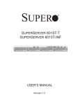
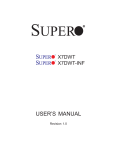
Figure 1-1 NovaScale R422 Motherboard (X7DBT/X7DBT-INF)
At the heart of the NovaScale R422/R422-INF server lies two (twin) NovaScale R422
X7DBT or two NovaScale X7DBT-INF dual processor server boards, which are based on
Intel's 5000P chipset. Below are the main features of the NovaScale R422 X7DBT/X7DBTINF motherboard. Note that the features on each board are doubled for the server.
Processors
Each NovaScale R422 X7DBT/X7DBT-INF motherboard supports dual Intel® 5300/5100
Series processors.
Memory
The NovaScale R422 X7DBT/X7DBT-INF motherboard has eight 240-pin DIMM sockets
that can support up to 32 GB of ECC FBD (Fully Buffered DIMM) DDR2-667/533 SDRAM.
Memory can be installed in both interleaved (dual-channel) and non-interleaved (singlechannel) configurations. All memory modules used to populate the system should be the
same size, type and speed.
Serial ATA
The South Bridge (ESB2) of the 5000P chipset includes a Serial ATA controller for 3 Gb/s
SATA drives. The hot-swappable SATA drives are connected to a backplane that provides
power, bus termination and configuration settings. RAID 0 and 1 are supported.
PCI Expansion Slots
Each NovaScale R422 X7DBT/X7DBT-INF motherboard has one PCI-Express x8 slot, so
two PCI-Express x8 slots are provided in the server. In the NovaScale R422/R422-INF
server configuration, riser cards have been pre-installed to support two low-profile PCIExpress x8 add-on cards.
Ethernet Ports
Two Intel® 82563EB network controllers are integrated into the 5000P chipset on each
1-2
NovaScale R422 Installation and User's Guide
of the server boards to support a total of four Gigabit LAN ports (100/1000 BaseT/1000BaseTX, RJ45 output).
Onboard Controllers/Ports
An onboard IDE controller supports Ultra ATA 100 hard drives or ATAPI devices. Onboard
I/O back panel ports include one COM port, a VGA port, two USB ports, two Gigabit
LAN (NIC) ports and (on the NovaScale R422-INF only) an InfiniBand® port. There are
two sets of I/O ports included in the server (one set for each sever board).
!
InfiniBand Port Bracket:
The InfiniBand port bracket is a small "U" shaped bracket that secures the connector to
the I/O port shield. This allows the I/O shield, not the serverboard, to support the cable's
weight. The bracket can be found on the connector itself.
When installing the serverboard, remove the bracket from the InfiniBand port. Slide the
port through the shield, and then replace the bracket to secure the port to the I/O shield.
ATI Graphics Controller
The NovaScale R422 X7DBT/X7DBT-INF motherboard features an integrated ATI video
controller based on the ES1000 graphics chip. The ES1000 was designed specifically for
servers, featuring low power consumption, high reliability and superior longevity.
Introduction
1-3
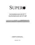
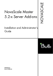
Figure 1-2 . Intel 5000P Chipset: System Block Diagram
NOTE: This is a general block diagram. Please see Chapter 5 for details.
1-4
NovaScale R422 Installation and User's Guide
1-3
Server Chassis Features
The following is a general outline of the main features of the NovaScale R422/R422-INF
(CSE-808T-980B)1U chassis. Details on the chassis can be found in Chapter 6.
System Power
When configured as a NovaScale R422/R422-INF server, the NovaScale R422/R422-INF
(CSE-808T-980B) box includes a single 980 W cold-swap power supply, which provides
the power to both server boards housed in the chassis.
SATA Subsystem
The NovaScale R422/R422-INF (CSE-808T-980B) chassis was designed to support four
SATA hard drives, which are hot-swappable units.
Control Panel
The NovaScale R422/R422-INF (CSE-808T-980B) box features two independant control
panels associated with each serverboard in the chassis. Each control panel has LEDs
to indicate power on, network activity, hard disk drive activity and system overheat
conditions. Each control panel also includes a main power button and a system reset
button.
Rear I/O Panel
The NovaScale R422/R422-INF (CSE-808T-980B) is a 1U rackmount chassis. Its I/O panel
provides a slots for two low-profile PCI-E x8 expansion cards, two COM ports, four USB
ports, two VGA ports and four Gb Ethernet ports. The NovaScale R422-INF also provides
two InfiniBand ports. See Chapter 6 for details.
Cooling System
The NovaScale R422/R422-INF (CSE-808T-980B)chassis has an innovative cooling design
that features two sets of triple (for a total of six) 4 cm high-performance fans. A fan speed
control setting in BIOS allows fan speed to be determined by system temperature.
Introduction
1-5
1-4
1U Twin: System Notes
As a 1U Twin configuration, the NovaScale R422/R422-INF is a unique server system.
With two system boards incorporated into a single chassis, there are several points you
should keep in mind.
System Power
A single power supply is used to provide the power for both server boards. Each
serverboard however, can be shut down independently of the other with the power button
on its own control panel.
Although they share a common power supply, the I2C signals used for power supply
monitoring are received by the primary serverboard only. (When viewed from the front
of the chassis, the serverboard on the left is referred to as the primary board and the
serverboard on the right as the secondary).
SATA Backplane/Drives
As a system, the NovaScale R422/R422-INF supports the use of four SATA drives. The
SATA backplane works as a single backplane divided into two sections. This means that
while a single power connector is used and functions such as overheating apply to both
sections together, each pair of SATA drives is logically connected to its own serverboard.
Consequently, RAID setup is limited to a two-drive scheme (RAID cannot be spread across
all four drives).
1-5
Contacting Bull S.A.S.
For details on contacting Bull S.A.S go to http://support.bull.com
1-6
NovaScale R422 Installation and User's Guide
Chapter 2 Server Installation
2-1
Overview
This chapter provides a quick setup checklist to get your NovaScale R422/R422-INF server
up and running. Following these steps, in the order given, should enable you to have the
system operational within a minimum amount of time. This quick setup assumes that your
system has come to you with the processors and memory pre-installed. If your system is not
already fully integrated with a serverboard, processors, system memory etc., please turn to
the chapter or section noted in each step for details on installing specific components.
2-2
Unpacking the System
You should inspect the box the NovaScale R422/R422-INF was shipped in and note if
it was damaged in any way. If the server itself shows damage you should file a damage
claim with the carrier who delivered it.
Decide on a suitable location for the rack unit that will hold the NovaScale R422/
R422-INF. It should be situated in a clean, dust-free area that is well ventilated. Avoid areas
where heat, electrical noise and electromagnetic fields are generated. You will also need it
placed near a grounded power outlet. Be sure to read the Rack Mounting Considerations
in the next section.
2-3
Preparing for Setup
The box the NovaScale R422/R422-INF server was shipped in should include two sets of
rail assemblies, two rail mounting brackets and the mounting screws you will need to install
the system into the rack. Follow the steps in the order given to complete the installation
process in a minimum amount of time. Please read this section in its entirety before you
begin the installation procedure outlined in the sections that follow.
Choosing a Setup Location
•
Leave enough clearance in front of the rack to enable you to open the front door
completely 63,5 cm (~25 inches).
•
Leave approximately 76,2 cm (~30 inches) of clearance in the back of the rack to
allow for sufficient airflow and ease in servicing.
•
This product is for installation only in a Restricted Access Location (dedicated
equipment rooms, service closets and the like).
Server Installation
2-1
!
Warnings and Precautions!
Rack Precautions
•
Ensure that the leveling jacks on the bottom of the rack are fully extended to the floor
with the full weight of the rack resting on them.
•
In single rack installation, stabilizers should be attached to the rack.
•
In multiple rack installations, the racks should be coupled together.
•
Always make sure the rack is stable before extending a component from the rack.
•
You should extend only one component at a time - extending two or more
simultaneously may cause the rack to become unstable.
Server Precautions
•
Review the electrical and general safety precautions in Chapter 4.
•
Determine the placement of each component in the rack before you install the rail.
•
Install the heaviest server components on the bottom of the rack first, and then work
up.
•
Use a regulating uninterruptible power supply (UPS) to protect the server from power
surges, voltage spikes and to keep your system operating in case of a power failure.
•
Allow the hot plug SATA drives and power supply modules to cool before touching
them.
•
Always keep the rack's front door and all panels and components on the servers
closed when not servicing to maintain proper cooling.
Rack Mounting Considerations
Ambient Operating Temperature
If installed in a closed or multi-unit rack assembly, the ambient operating temperature of
the rack environment may be greater than the ambient temperature of the room. Therefore,
consideration should be given to installing the equipment in an environment compatible
with the manufacturer’s maximum rated ambient temperature (Tmra), see Appendix D.
Reduced Airflow
Equipment should be mounted into a rack so that the amount of airflow required for safe
operation is not compromised.
Mechanical Loading
Equipment should be mounted into a rack so that a hazardous condition does not arise due
to uneven mechanical loading.
2-2
NovaScale R422 Installation and User's Guide
Circuit Overloading
Consideration should be given to the connection of the equipment to the power supply
circuitry and the effect that any possible overloading of circuits might have on overcurrent
protection and power supply wiring. Appropriate consideration of equipment nameplate
ratings should be used when addressing this concern.
Reliable Ground
A reliable ground must be maintained at all times. To ensure this, the rack itself should be
grounded. Particular attention should be given to power supply connections other than the
direct connections to the branch circuit (i.e. the use of power strips, etc.).
Server Installation
2-3
2-4
Installing the System into a Rack
This section provides information on installing the NovaScale R422/R422-INF server into
a rack unit with the rack rails provided. If the system has already been mounted into a
rack, you can skip ahead to Sections 2-5 and 2-6. There are a variety of rack units on the
market, which may mean the assembly procedure will differ slightly. You should also refer
to the installation instructions that came with the rack unit you are using.
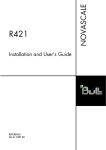
Identifying the Sections of the Rack Rails
You should have received two rack rail assemblies in the rack mounting kit. Each assembly
consists of two sections: an inner fixed chassis rail that secures directly to the server chassis
and an outer fixed rack rail that secures directly to the rack itself (see Figure 2-1). Two pairs
of short brackets to be used on the front side of the outer rails are also included.
Installing the Inner Rails
Both the left and right side inner rails have been pre-attached to the chassis. Proceed to the
next step.
Figure 2-1. Identifying the Sections of the Rack Rails (right side rail shown)
Installing the Outer Rails
Begin by measuring the distance from the front rail to the rear rail of the rack. Attach a
short bracket to the front side of the right outer rail and a long bracket to the rear side of
the right outer rail. Adjust both the short and long brackets to the proper distance so that
the rail can fit snugly into the rack. Secure the short bracket to the front side of the outer rail
with two M4 screws and the long bracket to the rear side of the outer rail with three M4
screws. Repeat these steps for the left outer rail.
Locking Tabs
Both chassis rails have a locking tab, which serves two functions. The first is to lock the
server into place when installed and pushed fully into the rack, which is its normal position.
Secondly, these tabs also lock the server in place when fully extended from the rack,
This prevents the server from coming completely out of the rack when you pull it out for
servicing.
2-4
NovaScale R422 Installation and User's Guide
Figure 2-2. Installing the Rack Rails
You should now have rails attached to both the chassis and the rack unit. The next step is to
install the server into the rack. Do this by lining up the rear of the chassis rails with the front
of the rack rails. Slide the chassis rails into the rack rails, keeping the pressure even on
both sides (you may have to depress the locking tabs when inserting). See Figure 2-3.
When the server has been pushed completely into the rack, you should hear the locking
tabs "click". Finish by inserting and tightening the thumbscrews that hold the front of the
server to the rack.
Server Installation
2-5
Figure 2-3. Installing the Server into a Rack
2-5
Checking the Serverboard Setup
After you install the NovaScale R422/R422-INF server in its rack, you will need to open
the top cover to make sure the serverboard is properly installed and all the connections
have been made.
1.
Accessing the inside of the System (see Figure 2-4)
First, release the retention screws that secure the system to the rack. Grasp the two handles
on either side and pull the system straight out until it locks (you will hear a "click"). Next,
remove the four screws (two on the sides and two on the top) that secure the top cover to
the chassis. Place your thumbs in the two rectangular recesses and push the cover away
from you (toward the rear of the chassis) until it stops. You can then lift the top cover from
the chassis to gain full access to the inside of the server.
To remove the system from the rack completely, depress the locking tabs in the chassis rails
(push the right-side tab down and the left-side tab up) to continue to pull the system out past
the locked position.
2-6
NovaScale R422 Installation and User's Guide
2.
Check the CPUs (processors)
You may have one or two processors already installed in each of the two serverboards.
Each processor needs its own heatsink. See Chapter 5 for instructions on processor and
heatsink installation.
3.
Check the system memory
Your server system may have come with system memory already installed. Make sure
all DIMMs are fully seated in their slots. For details on adding system memory, refer to
Chapter 5.
4.
Installing add-on cards
You can install two add-on cards to the system. See Chapter 5 for details on installing PCI
add-on cards.
5.
Check all cable connections and airflow
Make sure all power and data cables are properly connected and not blocking the chassis
airflow. See Chapter 5 for details on cable connections.
Figure 2-4. Accessing the Inside of the System
Server Installation
2-7
2-6
Checking the Drive Bay Setup
Next, you should check to make sure the peripheral drives and the SATA drives and SATA
backplane have been properly installed and all connections have been made.
1.
Check the SATA drives
Depending upon your system's configuration, your system may have one or more drives
already installed. If you need to install SATA drives, please refer to Chapter 6.
2.
Check the airflow
Airflow is provided by six sets of 4-cm fans (each set of fans consists of two fans that are
mounted back to back). The system component layout was carefully designed to direct
sufficient cooling airflow to the components that generate the most heat. Note that all
power and data cables have been routed in such a way that they do not block the airflow
generated by the fans.
3.
Supplying power to the system
The last thing you must do is to provide input power to the system. Plug the power cord
from the power supply module into a high-quality power strip that offers protection from
electrical noise and power surges. It is recommended that you use an uninterruptible power
supply (UPS) source.
2-8
NovaScale R422 Installation and User's Guide
Chapter 3 System Interface
3-1
Overview
There are several LEDs on the two control panels as well as others on the SATA drive
carriers to keep you constantly informed of the overall status of the system as well as the
activity and health of specific components. There are also two buttons on each control
panel. This chapter explains the meanings of all LED indicators and the appropriate
response you may need to take.
NOTE : The server has two control panels, one for each serverboard installed in the
system. This allows each severboard to be controlled independently of the
other.
3-2
Control Panel Buttons
There are two push-button buttons located on each control panel: a reset button and a
power on/off button.
3-3
•
RESET : Depressing the reset button will reboot only the serverboard it is associated
with.
•
POWER : This is the main power button, which is used to apply or turn off the main
system power for the serverboard it is connected to only. Depressing this button
removes the main power but keeps standby power supplied to the serverboard.
Control Panel LEDS
Each of the two control panels located on the front of the NovaScale R422/R422-INF box
(CSE-808T-980B) has five LEDs. Each LED provides you with critical information related its
own specific serverboard. This section explains what each LED indicates when illuminated
and any corrective action you may need to take.
•
Overheat/Fan Fail : When this LED flashes, it indicates a fan failure. When on
continuously it indicates an overheat condition, which may be caused by cables
System Interface
3-1
obstructing the airflow in the system or the ambient room temperature being too warm.
Check the routing of the cables and make sure all fans are present and operating
normally. You should also check to make sure that the chassis covers are installed.
Finally, verify that the heatsinks are installed properly (see Chapter 5). This LED will
remain flashing or on as long as the indicated condition exists.
2
•
NIC2 : Indicates network activity on LAN2 when flashing .
1
3-4
•
NIC1 : Indicates network activity on LAN1 when flashing.
•
HDD : Channel activity for the hard disk drives. This light indicates SATA drive activity
on the NovaScale R422/R422-INF server when flashing.
•
Power : Indicates power is being supplied to the system's power supply unit. This LED
should normally be illuminated when the system is operating.
SATA Drive Carrier LEDs
Each SATA drive carrier has two LEDs.
3-2
•
Green : When illuminated, the green LED on the front of the SATA drive carrier
indicates drive activity. A connection to the SATA backplane enables this LED to blink
on and off when that particular drive is being accessed.
•
Red : The red LED indicates two states. When blinking, it indicates the drive is
rebuilding. When solid, it indicates a drive failure. If a SATA drive fails, you should
be notified by your system management software. Please refer to Chapter 6 for
instructions on replacing failed SATA drives.
NovaScale R422 Installation and User's Guide
Chapter 4 System Safety
4-1
Electrical Safety Precautions
Basic electrical safety precautions should be followed to protect yourself from harm and the
NovaScale R422/R422-INF server rom damage:
!
4-2
•
Be aware of the locations of the power on/off switch on the chassis as well as the
room's emergency power-off switch, disconnection switch or electrical outlet. If an
electrical accident occurs, you can then quickly remove power from the system.
•
Do not work alone when working with high voltage components.
•
Power should always be disconnected from the system when removing or installing
main system components, such as the server boards, memory modules and processors
(not SATA drives). When disconnecting power, you should first power down the
system with the operating system first and then unplug the power cord from the power
supply unit.
•
When working around exposed electrical circuits, another person who is familiar with
the power-off controls should be nearby to switch off the power if necessary.
•
Use only one hand when working with powered-on electrical equipment. This is to
avoid making a complete circuit, which will cause electrical shock. Use extreme
caution when using metal tools, which can easily damage any electrical components
or circuit boards they come into contact with.
•
Do not use mats designed to decrease static electrical discharge as protection from
electrical shock. Instead, use rubber mats that have been specifically designed as
electrical insulators.
•
The power supply power cord must include a grounding plug and must be plugged
into a grounded electrical outlet.
•
Serverboard Battery: CAUTION - There is a danger of explosion if the onboard battery
is installed upside down, which will reverse its polarities (see Figure 4-1). This battery
must be replaced only with the same or an equivalent type recommended by the
manufacturer. Dispose of used batteries according to the manufacturer's instructions.
General Safety Precautions
Follow these rules to ensure general safety:
!
•
Keep the area around the NovaScale R422/R422-INF server clean and free of clutter.
•
The NovaScale R422/R422-INF server weighs approximately 18.2 kg (~ 40 lbs)
when fully loaded. When lifting the system, two people at either end should lift slowly
with their feet spread out to distribute the weight. Always keep your back straight and
lift with your legs.
•
Place the chassis top cover and any system components that have been removed away
System Safety
4-1
from the system or on a table so that they won't accidentally be stepped on.
4-3
•
While working on the system, do not wear loose clothing such as neckties and
unbuttoned shirt sleeves, which can come into contact with electrical circuits or be
pulled into a cooling fan.
•
Remove any jewelry or metal objects from your body, which are excellent metal
conductors that can create short circuits and harm you if they come into contact with
printed circuit boards or areas where power is present.
•
After accessing the inside of the system, close the system back up and secure it to the
rack unit with the retention screws after ensuring that all connections have been made.
ESD Precautions
Electrostatic discharge (ESD) is generated by two objects with different electrical charges
coming into contact with each other. An electrical discharge is created to neutralize this
difference, which can damage electronic components and printed circuit boards. The
following measures are generally sufficient to neutralize this difference before contact is
made to protect your equipment from ESD:
!
4-2
•
Use a grounded wrist strap designed to prevent static discharge.
•
Keep all components and printed circuit boards (PCBs) in their antistatic bags until
ready for use.
•
Touch a grounded metal object before removing the board from the antistatic bag.
•
Do not let components or PCBs come into contact with your clothing, which may retain
a charge even if you are wearing a wrist strap.
•
Handle a board by its edges only; do not touch its components, peripheral chips,
memory modules or contacts.
•
When handling chips or modules, avoid touching their pins.
•
Put the serverboard and peripherals back into their antistatic bags when not in use.
•
For grounding purposes, make sure your computer chassis provides excellent
conductivity between the power supply, the case, the mounting fasteners and the
serverboard.
NovaScale R422 Installation and User's Guide
4-4
Operating Precautions
!
Care must be taken to assure that the chassis cover is in place when the NovaScale R422/
R422-INF server is operating to assure proper cooling. Out of warranty damage to the
NovaScale R422/R422-INF system can occur if this practice is not strictly followed.
Figure 4-1. Installing the Onboard Battery
The voltage of the Onboard Battery (For example : CR-2032) is 3.3v
System Safety
4-3
4-4
NovaScale R422 Installation and User's Guide
Chapter 5 Advanced Serverboard Setup
This chapter covers the steps required to install the NovaScale R422 X7DBT/X7DBT-INF
motherboard into the NovaScale R422/R422-INF box (NovaScale R422/R422-INF
box (CSE-808T-980B) , connect the data and power cables and install add-on cards. All
serverboard jumpers and connections are also described. A layout and quick reference
chart are included in this chapter for your reference. Remember to completely close the
chassis when you have finished working with the serverboard to better cool and protect the
system.
5-1
Handling the Serverboard
Electrostatic discharge (ESD) can damage electronic components. To prevent damage
to any printed circuit boards (PCBs), it is important to handle them very carefully (see
previous chapter). To prevent the NovaScale R422 NovaScale R422 X7DBT/X7DBT-INF
motherboard from bending, keep one hand under the center of the board to support it
when handling. The following measures are generally sufficient to protect your equipment
from electric static discharge.
•
Precautions
•
Use a grounded wrist strap designed to prevent Electrostatic Discharge (ESD).
•
Touch a grounded metal object before removing any board from its antistatic bag.
•
Handle a board by its edges only; do not touch its components, peripheral chips,
memory modules or gold contacts.
•
When handling chips or modules, avoid touching their pins.
•
Put the serverboard, add-on cards and peripherals back into their antistatic bags when
not in use.
•
For grounding purposes, make sure your computer chassis provides excellent
conductivity between the power supply, the case, the mounting fasteners and the
serverboard.
Unpacking
The serverboard is shipped in antistatic packaging to avoid electrostatic discharge. When
unpacking the board, make sure the person handling it is static protected.
Advanced Serverboard Setup
5-1
5-2
Serverboard Installation
This section explains the first step of physically mounting the NovaScale R422 X7DBT/
X7DBT-INF motherboard into the NovaScale R422/R422-INF box (NovaScale R422/R422INF box (CSE-808T-980B). Following the steps in the order given will eliminate the most
common problems encountered in such an installation. To remove the serverboard, follow
the procedure in reverse order.
1. Accessing the inside of the system (see Figure 2-5)
The top cover of the chassis is secured with four screws: two at the top rear of the cover
and one on each side lip, also near the back. Remove all four, then place both thumbs in
the indentations and push the cover back until it slides off. You can then lift the top cover
from the chassis to gain full access to the inside of the server. (If already installed in a rack,
you must first release the retention screws that secure the unit to the rack. Then grasp the
two handles on either side and pull the unit straight out until the rails lock into place.)
2. Check compatibility of serverboard ports and I/O shield
The NovaScale R422 X7DBT/X7DBT-INF motherboard in a Twin 1U configuration requires
the use of Bull's specially designed 1U Twin chassis: the NovaScale R422/R422-INF box
(CSE-808T-980B). Make sure that the I/O ports on the server boards align properly with
their respective holes in the I/O shield at the back of the chassis when installing.
3. Mounting the serverboard onto the serverboard tray
Carefully mount the server boards by aligning the board holes with the raised metal
standoffs that are visible in the chassis. Insert screws into all the mounting holes on your
server boards that line up with the standoffs and tighten until snug (if you screw them in
too tight, you might strip the threads). Metal screws provide an electrical contact to the
serverboard ground to provide a continuous ground for the system.
5-3
Connecting Cables
Now that the server boards are installed, the next step is to connect the cables to the
boards. These include the data cables for the peripherals and control panel and the power
cables.
Connecting Data Cables
The cables used to transfer data from the peripheral devices have been carefully routed to
prevent them from blocking the flow of cooling air that moves through the system from front
to back. If you need to disconnect any of these cables, you should take care to keep them
routed as they were originally after reconnecting them (make sure the red wires connect
to the pin 1 locations). The following data cables (with their locations noted) should be
connected. (See the layout on page 5-9 for connector locations.)
NOTE: Each connection listed should be made for both server boards in the chassis.
z SATA drive cables (SATA1)
z Control Panel cable (JF1)
5-2
NovaScale R422 Installation and User's Guide
Connecting Power Cables
The NovaScale R422 X7DBT/X7DBT-INF motherboard has two 20-pin ATX power supply
connectors for connection to the ATX power supply. Only one of these from each board
should be connected to the power supply. The "Primary ATX Power Header" is used to
supply power to the primary serverboard and the "Secondary ATX Power Header" is used
to supply power to the secondary serverboard. Connect the power supply to only one of
these on both boards (primary = left, secondary = right when viewed from front of server).
See Section 5-9 for power connector pin definitions.
Connecting the Control Panel
JF1 contains header pins for various front control panel connectors. See Figure 5-1 for the
pin locations of the various front control panel buttons and LED indicators. All JF1 wires
have been bundled into a single ribbon cable to simplify this connection. Make sure the red
wire plugs into pin 1 as marked on the board. The other end connects to the Control Panel
PCB board, located just behind the system status LEDs on the chassis.
20 19
Ground
NMI
x (Key)
x (Key)
Power On LED
Vcc 5V Stby
IDE/SATA LED
Vcc 3V
NIC1 LED
Vcc 3V Stby
NIC2 LED
Vcc 3V Stby
OH/Fan Fail LED
Vcc 3V
Reserved
Reserved
Ground
Reset (Button)
Ground
Power (Button)
2 1
Figure 5-1. Control Panel Header Pins
Advanced Serverboard Setup
5-3
5-4
I/O Ports
The I/O ports are color coded in conformance with the PC 99 specification. See Figure
5-2, below, for the colors and locations of the various I/O ports.
2
3
1
4
5
6
7
Figure 2-3. Back Panel I/O Port Locations and Definitions
Back Panel Connectors
1.
Back Panel USB Port 0
2.
Back Panel USB Port 1
3.
Gigabit LAN 1
4.
Gigabit LAN 2
5.
COM Port 1 (Turquoise)
6.
VGA Port (Blue)
7.
InfiniBand Connector (for X7DBT-INF only)
NOTE : InfiniBand ports are included on the NovaScale R422-INF only. To prevent
damage to the port or serverboard, an InfiniBand bracket (included) must
be used to secure the connector to the I/O shield.
5-4
NovaScale R422 Installation and User's Guide
5-5
Processor and Heatsink Installation
When handling the processor, avoid placing direct pressure on the label area of
the fan. Also, do not place the serverboard on a conductive surface, which can
damage the BIOS battery and prevent the system from booting up.
!
IMPORTANT! Always connect the power cord last and remove it first before adding,
removing or changing any hardware components. Make sure that you install the processor
into the CPU socket before you install the heatsink and fan. The NovaScale R422 X7DBT/
X7DBT-INF motherboard can support either one or two Xeon 5300/5100 type processors.
If installing one processor only, install it into CPU socket #1.
NOTES:
1.
Intel's boxed Xeon CPU package contains a CPU fan and heatsink assembly. If you buy a
CPU separately, make sure that you use only Intel-certified multi-directional heatsinks and
fans.
2.
When purchasing a Xeon 5300/5100 CPU or when receiving a serverboard with a CPU
pre-installed, make sure that the CPU plastic cap is in place and none of the CPU pins are
bent; otherwise, contact the retailer immediately.
Installing the Processor
1.
2.
A black PnP cap is attached to the
load plate to protect the CPU socket.
Press the load lever down and away
from the retention clasp to release the
load plate from its locked position.
Gently lift the load lever to open the
load plate.
Load lever
PnP cap
Load plate released
Advanced Serverboard Setup
5-5
3.
Use your thumb and your index finger
to hold the CPU at opposite sides.
4.
Align pin1 of the CPU (the corner
marked with a triangle) with the
notched corner of the CPU socket.
5.
Find the corner of the CPU that has
a semi-circle cutout below a gold
dot (CPU key). This corner should be
aligned with the cutout on the socket
(socket key).
6.
Gold dot
Socket key
Once aligned, carefully lower the CPU
straight down into the socket. Do not
drop the CPU on the socket, do not
move the CPU horizontally or vertically
and do not rub the CPU against
any surface or any of the contacts,
which may damage the CPU and/or
contacts.
CPU key
Notched corner
CPU pin 1
7.
With the CPU in the socket, inspect the
four corners of the CPU to make sure
that it is properly installed.
8.
Use your thumb to gently push the
load lever down until it snaps into the
retention clasp.
9.
!
Load lever
If the CPU is properly installed into
the socket, the PnP cap will be
automatically released from the load
plate when the lever locks. Remove the
cap. Repeat steps to install a second
CPU if desired.
WARNING! Keep the plastic PnP cap.
The serverboard must be shipped with
the PnP cap properly installed to
protect the CPU socket. Shipment
without the PnP cap properly installed
will void the warranty.
PnP cap released
from load plate
5-6
NovaScale R422 Installation and User's Guide
CPU installed in socket
Installing the Heatsink
1.
Do not apply any thermal grease to the
heatsink or the CPU die; the required
amount has already been applied.
2.
Place the heatsink on top of the CPU
so that the four mounting holes are
aligned with those on the (pre-installed)
heatsink retention mechanism.
3.
Screw in two diagonal screws (i.e. the
#1 and the #2 screws) until just snug.
Do not fully tighten the screws or you
may damage the CPU.)
4.
Add the two remaining screws then
finish the installation by fully tightening
all four screws.
Removing the Heatsink
Warning! We do not recommend that the CPU or the heatsink be removed. However,
if you do need to uninstall the heatsink, please follow the instructions below to
prevent damage to the CPU or the CPU socket.
!
1.
Unscrew and remove the heatsink screws from the serverboard in the sequence as show in
the picture above.
2.
Hold the heatsink and gently wriggle the heatsink to loosen it from the CPU. (Do not use
excessive force when wriggling the heatsink!!)
3.
Once the heatsink is loose, remove it from the CPU.
4.
Clean the surface of the CPU and the heatsink to get rid of the old thermal grease. Reapply
the proper amount of thermal grease on the surface before you re-install the heatsink.
Advanced Serverboard Setup
5-7
5-6
Installing Memory
CAUTION
Exercise extreme care when installing or removing DIMM modules to prevent any
possible damage. Also note that the memory is interleaved to improve performance
(see step 1).
DIMM Installation (See Figure 2-2)
1.
Insert the desired number of DIMMs into the memory slots, starting with DIMM #1A. The
memory scheme is interleaved so you must install two modules at a time, beginning with
DIMM #1A, then DIMM #2A and so on. For optimal performance, please install four
modules of the same type and same speed in Branch 0 and Branch 1 at a time (up to 8
modules maximum). (See the Memory Installation Table Below.)
2.
Insert each DIMM module vertically into its slot. Pay attention to the notch along the bottom
of the module to prevent inserting the DIMM module incorrectly.
3.
Gently press down on the DIMM module until it snaps into place in the slot. Repeat for all
modules (see step 1 above).
Memory Support
The NovaScale R422 X7DBT/X7DBT-INF motherboard supports up to 32 GB fully buffered
(FBD) ECC DDR2 533/667 in 8 DIMMs. Populating DIMM modules with pairs of memory
modules of the same size and same type will result in Interleaved Memory which will
increase memory performance.
NOTE : Due to OS limitations, some operating systems may not show more than 4 GB
of memory.
Optimized DIMM Population Configurations
Branch 0
Branch 1
Number of DIMMs
Bank 1
(Channel 0)
Bank 2
(Channel 1)
Bank 3
(Channel 2)
Bank 4
(Channel 3)
2 DIMMs
1A
---
2A
---
---
---
---
---
4 DIMMs
1A
---
2A
---
3A
---
4A
---
6 DIMMs
1A
1B
2A
2B
3A
---
4A
---
8 DIMMs
1A
1B
2A
2B
3A
3B
4A
4B
NOTES
i.
DIMM slot# specified: DIMM slot to be populated; “---“: DIMM slot not to be populated.
ii.
Both FBD 533 MHz and 667 MHz DIMMs are supported; however, you need to use the
memory modules of the same speed and of the same type on a motherboard.
iii. Interleaved memory is supported when pairs of DIMM modules are installed. To optimize
memory performance, please populate pairs of memory modules in both Branch 0 and
Branch 1.
iv. For memory to work properly, you need to follow the restrictions listed above.
5-8
NovaScale R422 Installation and User's Guide
NOTE : Due to memory allocation to system devices, memory remaining available for
operational use will be reduced when 4 GB of RAM is used. The reduction in
memory availability is disproportional. (Refer to the Memory Availability Table
below for details.)
Possible System Memory Allocation & Availability
System Device
Size
Physical Memory
Remaining (-Available)
(3 GB Total System Memory)
Physical Memory
Remaining (-Available)
(4 GB Total System Memory)
Firmware Hub flash
memory (System BIOS)
1 MB
3.00
3.99
Local APIC
4 KB
3.00
3.99
Area Reserved for the
chipset
2 MB
3.00
3.99
I/O APIC (4 Kbytes)
4 KB
3.00
3.99
PCI Enumeration Area 1
256 MB
3.00
3.76
PCI Express (256 MB)
256 MB
3.00
3.51
PCI Enumeration Area 2
(if needed) -Aligned on
256-MB boundary-
512 MB
3.00
3.01
16 MB
2.85
2.85
1 MB
2.84
2.84
2.84
2.84
VGA Memory
TSEG
Memory available to OS
& other applications
Figure 5-3. Installing and Removing DIMMs
2 FBD
To Install
Insert module vertically and press down until it snaps into place. Pay attention to the
alignment notch at the bottom.
2 FBD
To Remove
Use your thumbs to gently push the release tabs near both ends of the module. This should
release it from the slot.
Advanced Serverboard Setup
5-9
5-7
Adding PCI Cards
64-bit PCI-X slot
The NovaScale R422/R422-INF includes two pre-installed riser cards designed specifically
for use in the NovaScale R422/R422-INF box (CSE-808T-980B) 1U rackmount chassis.
These riser cards support two low-profile PCI-Express x8 cards to fit inside the chassis.
PCI card installation
The riser card has already been pre-installed into the serverboard. Perform the following
steps to add a PCI add-on card:
5-10
1.
Remove the PCI slot shield on the chassis by releasing the locking tab.
2.
Insert the add-on card into the riser card.
3.
Secure the add-on card with the locking tab.
NovaScale R422 Installation and User's Guide
5-8
Serverboard Details
USB0/1
COM2
LE3 LE2
LAN1
VGA
LAN2
InfiniBand
BIOS
JPG1
JWOL
JWOR
Battery
SIMSO
PCI-Express x8
ATI
ES1000
Speaker
JP1
JP7
JBT1
J18
JI2C1
JI2C2
SGPIO
JPL1
SATA3
SATA2
JPL2
DIMM 4B (Bank4)
DIMM 3B (Bank3)
DIMM 4A (Bank4)
DIMM 2B (Bank2)
DIMM 3A (Bank3)
DIMM 1B (Bank1)
®
JOH1
JL1
DIMM 2A (Bank2)
JUSB2
X7DBT-INF
ESB2
DIMM 1A (Bank1)
SATA1
SATA0
South Bridge
North Bridge
5000P
LE1
JWD
JF1
CPU2
CPU1
ATX Power 1
Fan1/2
Fan3/4
JP10
Fan5/6
Fan7/8
ATX Power 2
Primary
ATX Power
Header
Secondary
ATX Power
Header
J17
Figure 5-4. NovaScale R422 X7DBT/X7DBT-INF motherboard Layout (not drawn to scale)
Notes
Jumpers not indicated are for test purposes only.
The InfiniBand port is included on the X7DBT-INF only.
Advanced Serverboard Setup
5-11
NovaScale R422 X7DBT/X7DBT-INF Motherboard Quick Reference details
Jumper
JBT1
JI2C1/JI2C2
JPG1
JPL1/JPL2
JWD (JWD)
Connector
ATX Power 1
ATX Power 2
COM2
FAN 1-6
InfiniBand*
J17
J18
JF1
JL1
JOH1
JPI2C
JP10
JWOL
JWOR
LAN1/2
SATA0-SATA3
SGPIO
SIMSO IPMI
USB0/1
USB2/3
LED Indicator
LE1
LE2*
LE3*
Description
CMOS Clear
I2C to PCI-Express Slot
VGA Enable
LAN1/LAN2 Enable/Disable
Watch Dog
Default Setting
See Section 5-10
Open (Disabled)
Pins 1-2 (Enabled)
Pins 1-2 (Enabled)
Pins 1-2 (Reset)
Description
20-Pin ATX PWR Connector (for Primary Board)
20-Pin ATX PWR Connector (for Secondary Board)
COM2 Serial Port/Header
Chassis and CPU Fan Headers
InfiniBand Connector
System Management Power (I2C) Header
System Management Bus Header
Front Control Panel Connector
Chassis Intrusion Header
Overheat LED Header
System Management Power (I2C) Header
4-pin Auxiliary Power Connector (for HDDs)
Wake-on-LAN Header
Wake-on-Ring Header
Gigabit Ethernet Ports
Intel SATA 0-3 Ports
Serial ATA General Purpose Input/Output Header
SIMSO IPMI Socket
USB0/1 Ports
USB0/1 Headers
Description
Onboard Power LED Indicator
InfiniBand Link LED (green)
InfiniBand Activity LED (yellow)
*X7DBT-INF only
NOTE:
5-12
The "Primary ATX Power Header" is used to supply power to the primary
serverboard and the "Secondary ATX Power Header" is used to supply power
to the secondary serverboard. Connect the power supply to only one of these
on both boards (primary = left, secondary = right when viewed from front of
server).
NovaScale R422 Installation and User's Guide
5-9
Motherboard detailed features
CPU
•
Dual Intel® 64-bit Xeon LGA 771 dual core/quad core processors at a front side bus
speed of 1333 MHz, 1066 MHz or 667 MHz
Memory
•
Eight 240-pin DIMM sockets with support up to 32 GB DDR2 Fully Buffered (FBD) ECC
667/533 Memory.
Chipset
•
For the X7DBT/X7DBT-INF: Intel 5000P chipset, including: the 5000P Memory Control
Hub (MCH), and the Enterprise South Bridge 2 (ESB2).
Expansion Slots
•
One PCI-Express slot (*one PCI-E slot x8: JPCIE1)
BIOS
•
8 Mb Phoenix® Flash ROM
•
DMI 2.3, PCI 2.2, ACPI 1.0/2.0, Plug and Play (PnP), USB Keyboard
Support,SMBIOS 2.3
PC Health Monitoring
•
Onboard voltage monitors for CPU cores, chipset voltage (+1.5V), memory voltage,
+3.3V, +5V, +12V, -12V, +3.3V Standby, +5V standby, HT and VBAT
•
Fan status monitor with fi rmware control
•
CPU/chassis environment monitoring
•
Platform Environment Control Interface (PECI) ready
•
CPU fan auto-off in sleep mode
•
CPU slow-down on temperature overheat
•
CPU thermal trip support for processor protection, power LED
•
Power-up mode control for recovery from AC power loss
•
Auto-switching voltage regulator for CPU cores
•
System overheat/Fan Fail LED Indicator and control
•
Chassis intrusion detection
•
I2C temperature sensing logic
•
Thermal Monitor 2 (TM) support
ACPI Features
•
Slow blinking LED for suspend state indicator
•
Main switch override mechanism
•
ACPI Power Management
Advanced Serverboard Setup
5-13
Onboard I/O
•
Four SATA2 ports (supporting RAID0, 1, 10 and 5)
•
One SIMSO IPMI slot
•
One Intel Gigabit Ethernet 82563EB controller supports two Giga-bit LAN ports
•
One COM port
•
Up to four USB 2.0 (Universal Serial Bus) (2 ports, 2 Headers)
•
ATI ES1000 Graphic Controller with 16MB Video Memory
•
Super I/O: Winbond W83627HF
•
Mellanox MT25204A0-FCC-D InfiniBand Controller supports one InfiniBand connector
(Only on Novascale R422-INF (X7DBT-INF) motherboard)
Other
•
External modem ring-on
•
Wake-on-LAN (WOL)
•
Wake-on-Ring (WOR)
•
Console redirection
•
Onboard Fan Speed Control by Thermal Management via BIOS
Dimensions
•
Proprietary 16.0" x 6.5" (406.4 mm x 165.1 mm)
Chipset Overview
The Intel 5000P Chipset (for the X7DBT/X7DBT-INF) is built upon the functionality and
the capability of the 5000P chipset, the X7DBT/X7DBT-INF motherboard provides the
performance and feature set required for dual processor-based servers with configuration
options optimized for communications, presentation, storage, computation or database
applications. The 5000P chipset supports single or dual Xeon 64-bit dual core processor(s)
with front side bus speeds of up to 1.333 GHz. The chipset consists of the 5000P Memory
Controller Hub (MCH) and the Enterprise South Bridge 2 (ESB2).
The 5000P MCH chipset is designed for symmetric multiprocessing across two independent
front side bus interfaces. Each front side bus uses a 64-bit wide, 1333 MHz data bus
that transfers data at 10.7 GB/sec. The MCH chipset connects up to eight Fully Buffered
DIMM modules, providing a total memory of up to 32.0 GB for DDR2 667/533 MHz.
The MCH chipset also provides one x8 PCI-Express and one x4 ESI interfaces to the ESB2.
In addition, the 5000P chipset offers a wide range of RAS features, including memory
interface ECC, x4/x8 Single Device Data Correction, CRC, parity protection, memory
mirroring and memory sparing.
The Xeon Dual Core Processor Features
Designed to be used with conjunction of the 5000P chipset, the Xeon dual core Processor
provides a feature set as follows:
5-14
•
L1 Cache Size: Instruction Cache (32KB/16KB), Data Cache (32KB/24KB)
•
L2 Cache Size: 4MB/2MB (per core)
NovaScale R422 Installation and User's Guide
•
Data Bus Transfer Rate: 8.5 GB/s
•
Package: FC-LGA6/FC-LGA4, 771 Lands
Special Features
Recovery from AC Power Loss
The feature allows the user to set the power state after a power outage. You can select
Power-Off for the system power to remain off after a power loss. Select Power-On for the
system power to be turned on after a power loss. Select Last State to allow the system to
resume its last state before the power loss. The default setting is Last State.
5-10
PC Health Monitoring
NOTE: For more information on monitoring the performance and health of your server
see the Bull NovaScale R42x AOC-SIMSO/SIMSO+ Installation and User's
Guide and the Bull NovaScale Master User's Guide
This section describes the PC health monitoring features of the X7DBT/X7DBT-INF.
All models have an onboard System Hardware Monitor chip that supports PC health
monitoring.
An onboard voltage monitor will scan voltages, listed below, continuously. Once a voltage
becomes unstable, a warning is given or an error message is sent to the screen. Users can
adjust the voltage thresholds to define the sensitivity of the voltage monitor.
Monitored Voltages
Onboard Voltage Monitors for CPU Cores, Memory Voltage, Chipset Voltage
(+1.5V),+1.8V, +3.3V, +5V, +12V, -12V, +3.3V Standby, +5V standby, HT and VBAT
Fan Status Monitor with Firmware Control
The PC health monitor can check the RPM status of the cooling fans. The onboard CPU and
chassis fans are controlled by Thermal Management 2 (TM2) via BIOS (under Hardware
Monitoring in the Advanced Setting).
Environmental Temperature Control
The thermal control sensor monitors the CPU temperature in real time and will turn on
the thermal control fan whenever the CPU temperature exceeds a user-defined threshold.
The overheat circuitry runs independently from the CPU. Once it detects that the CPU
temperature is too high, it will automatically turn on the thermal fan control to prevent any
overheating damage to the CPU. The onboard chassis thermal circuitry can monitor the
overall system temperature and alert users when the chassis temperature is too high.
CPU Fan Auto-Off in Sleep Mode
The CPU fan is activated when the power is turned on. It continues to operate when the
system enters Standby mode. When in sleep mode, the CPU will not run at full power,
thereby generating less heat.
CPU Overheat LED and Control
Advanced Serverboard Setup
5-15
This feature is available when the user enables the CPU overheating warning function in
the BIOS. This allows the user to define an overheat temperature. When the temperature
exceeds a user pre-defined threshold, both overheat fan and warning LED are triggered.
5-11
ACPI Features
ACPI stands for Advanced Configuration and Power Interface. The ACPI specification
defines a flexible and abstract hardware interface that provides a standard way to
integrate power management features throughout a PC system, including its hardware,
operating system and application software. This enables the system to automatically turn on
and off peripherals such as CD-ROMs, network cards, hard disk drives and printers. This
also includes consumer devices connected to the PC such as VCRs, TVs, telephones and
stereos.
In addition to enabling operating system-directed power management, ACPI provides a
generic system event mechanism for Plug and Play and an operating system-independent
interface for configuration control. ACPI leverages the Plug and Play BIOS data structures
while providing a processor architecture-independent implementation that is compatible
with both Windows 2000 and Windows NT 5.0.
Slow Blinking LED for Suspend-State Indicator
When the CPU goes into a suspend state, the chassis power LED will start blinking to
indicate that the CPU is in suspend mode. When the user presses any key, the CPU will
wake up and the LED will automatically stop blinking and remain on.
Main Switch Override Mechanism
When a power supply is used, the power button can function as a system suspend button
to make the system enter a SoftOff state. The monitor will be suspended and the hard drive
will spin down. Pressing the power button again will cause the whole system to wake up.
During the SoftOff state, the power supply provides power to keep the required circuitry in
the system alive. In case the system malfunctions and you want to turn off the power, just
press and hold the power button for 4 seconds. This option can be set in the Boot Features
Section under Advanced Setup in the BIOS.
External Modem Ring-On
Wake-up events can be triggered by a device such as the external modem ringing when
the system is in the SoftOff state. Note that external modem ring-on can only be used with
an ATX 2.01 (or above) compliant power supply.
Wake-On-LAN (WOL)
Wake-On-LAN is defined as the ability of a management application to remotely power up
a computer that is powered off. Remote PC setup, updates and asset tracking can occur
after hours and on weekends so that daily LAN traffic is kept to a minimum and users are
not interrupted. The motherboard has a 3-pin header (WOL) to connect to the 3-pin header
on a Network Interface Card (NIC) that has WOL capability. In addition, an onboard LAN
controller can also support WOL without any connection to the WOL header. The 3-pin
WOL header is to be used with a LAN add-on card only.
5-16
NovaScale R422 Installation and User's Guide
5-12
Connector Definitions
ATX Power Connector
The main ATX power supply connectors
on the NovaScale R422 X7DBT/
X7DBT-INF motherboard meets the SSI
(Superset ATX) 24-pin specification.
Refer to the table on the right for the
pin definitions. Only one of the two
ATX power connectors from each
serverboard should be connected to
the power supply.
ATX Power 20-pin Connector
Pin Definitions (ATX Power 1/2)
Pin# Definition Pin # Definition
11
PS On
1
Ground
12
5VSB
2
Ground
13
Ground
3
Ground
14
Ground
4
Ground
15
Ground
5
Ground
16
NC2
6
NC1
17
12V
7
12V
18
12V
8
12V
19
12V
9
12V
20
12V
10
12V
Auxiliary Power
Pin Definitions (JP10)
Auxiliary Power Connector
A 4-pin 12V auxiliary power
connector is included to provide power
to hard drive disks. See the table on
the right for pin definitions.
Pin#
1
+12V
2
Ground
3
Ground
4
+5V
Auxiliary Power Connector
A 4-pin 12V auxiliary power
connector is included to provide power
to hard drive disks. See the table on
the right for pin definitions.
Reset Connector
The reset connector is located on pins
3 and 4 of JF1 and attaches to the
reset switch on the computer chassis.
See the table on the right for pin
definitions.
Overheat LED (OH)
Connect an LED to the OH connection
on pins 7 and 8 of JF1 to provide
advanced warning of chassis
overheating. Refer to the table on the
right for pin definitions.
Definition
Power Button
Pin Definitions (JF1)
Pin#
Definition
1
PW_ON
2
Ground
Reset Button
Pin Definitions (JF1)
Pin# Definition
3
Reset
4
Ground
OH/Fan Fail LED
Pin Definitions (JF1)
Pin# Definition
7
Vcc
8
Ground
Advanced Serverboard Setup
5-17
NIC2 (LAN2) LED
NIC2 LED
Pin Definitions (JF1)
The LED connections for LAN2 are
on pins 9 and 10 of JF1. Attach LAN
LED cables to display network activity.
See the table on the right for pin
definitions.
Pin#
Definition
9
Vcc
10
Ground
NIC1 (LAN1) LED
NIC1 LED
Pin Definitions (JF1)
The LED connections for LAN1 are on
pins 11 and 12 of JF1. Attach LAN
LED cables to display network activity.
See the table on the right for pin
definitions.
Pin# Definition
11
Vcc
12
Ground
HDD LED
HDD LED
Pin Definitions (JF1)
The HDD LED connection is located
on pins 13 and 14 of JF1. Attach the
hard drive LED cable here to display
disk activity (for any hard drives on the
system, including SAS, Serial ATA and
IDE). See the table on the right for pin
definitions.
Pin# Definition
13
Vcc
14
HD Active
Power On LED
Power LED
Pin Definitions (JF1)
The Power On LED connector is
located on pins 15 and 16 of JF1.
This connection is used to provide LED
indication of power being supplied to
the system. See the table on the right
for pin definitions.
Pin# Definition
NMI Button
15
5V Stby
16
Control
NMI Button
Pin Definitions (JF1)
The non-maskable interrupt button
header is located on pins 19 and 20
of JF1. Refer to the table on the right
for pin definitions.
Pin# Definition
19
Control
20
Ground
Fan Headers
The NovaScale R422 X7DBT/X7DBTINF motherboard has four 6-pin
proprietary fan headers. Each fan
header supports two 3-pin fans.
See the table on the right for pin
definitions.
NOTE: The onboard fan speed is
controlled by the CPU die temperature.
5-18
NovaScale R422 Installation and User's Guide
Fan Header Pin Definitions
(Fan1/2 - Fan7/8)
Pin # Definition
Pin # Definition
1
PWR (DC
Speed CTRL)
4
Ground
2
Tachometer for
Fan 1/3/5
5
Tachometer for
Fan 2/4/6
3
Ground
6
PWR (DC Speed
CTRL)
Chassis Intrusion
Chassis Intrusion
Pin Definitions (JL1)
The Chassis Intrusion header is
designated JL1. See the board layout
for the location of JL1 and the table on
the right for pin definitions.
Pin#
Universal Serial Bus (USB)
Definition
1
Intrusion Input
2
Ground
USB Ports Pin
Definitions (USB0/1)
There are two Universal Serial Bus
ports located on the I/O panel and
two additional USB headers located on
the serverboard. The headers, labeled
USB2 and USB3, can be used to
provide front side USB access (cables
not included). See the tables on the
right for pin definitions.
Pin#
Definition
1
+5V
2
PO-
3
PO+
4
Ground
5
N/A
USB Headers
Pin Definitions (USB1, USB2)
USB3/5
Pin # Definition
USB2/4
Pin # Definition
1
+5V
1
+5V
2
PO-
2
PO-
3
PO+
3
PO+
4
Ground
4
Ground
5
Key
5
No connection
LAN1/2 (Ethernet Ports)
Two gigabit Ethernet ports (designated
LAN1 and LAN2) are located beside
the VGA port on the I/O backplane.
These ports accept RJ45 type cables.
LAN1
LAN2
Wake-On-LAN
The Wake-On-LAN header is
designated JWOL on the serverboard.
See the table on the right for pin
definitions. You must enable the LAN
Wake-Up setting in BIOS to use this
function. (You must also have a LAN
card with a Wake-On-LAN connector
and cable to use this feature.)
Wake-On-LAN
Pin Definitions (JWOL)
Pin#
1
Definition
+5V Standby
2
Ground
3
Wake-up
Advanced Serverboard Setup
5-19
Wake-On-Ring
Wake-On-Ring
Pin Definitions (JWOR)
The Wake-On-Ring header is
designated JWOR. This function allows
your computer to receive and be
"awakened" by an incoming call when
in the suspend state. See the table on
the right for pin definitions. You must
also have a WOR card and cable to
use this feature.
Pin# Definition
1
Ground (Black)
2
Wake-up
Serial Port Pin Definitions
(COM2)
Serial Ports
One serial port is included on the
serverboard: COM2 is a port located
beside the VGA port. See the table on
the right for pin definitions.
Pin # Definition
Pin # Definition
1
DCD
6
DSR
2
RXD
7
RTS
3
TXD
8
CTS
4
DTR
9
RI
5
Ground
10
NC
NOTE: NC indicates no connection.
SGPIO Header
An SGPIO (Serial General Purpose
Input/Output) header is included
on the serverboard. This header is
used to communicate with the System
Monitoring chip on the backplane.
SGPIO is used to monitor SATA
activity. See the table on the right for
pin definitions.
SGPIO Headers Pin Definitions
(SGPIO)
Pin# Definition
1
*NC
2
*NC
3
Ground
4
DATA Out
5
Load
6
Ground
7
Clock
8
*NC
NOTE: NC indicates no connection.
SMB Power (I2C)
The header at JI2C is for I2C, which
may be used to monitor the status
of the power supply, fan and system
temperature. See the table on the right
for pin definitions.
SMB Power (I2C)
Pin Definitions (J17)
Pin# Definition
1
Clock
2
Data
3
Power Fail
4
Ground
5
+3.3V
SMB
A System Management Bus header
is located at J18. Connect the
appropriate cable here to utilize SMB
on your system.
5-20
NovaScale R422 Installation and User's Guide
Pin Definition
SMB Header
Pin Definitions
Pin# Definition
1
Data
2
Ground
3
Clock
4
No Connection
5-13
Jumper Settings
Explanation of Jumpers
To modify the operation of the
serverboard, jumpers can be used
to choose between optional settings.
Jumpers create shorts between two
pins to change the function of the
connector. Pin 1 is identified with
a square solder pad on the printed
circuit board. See the serverboard
layout pages for jumper locations.
NOTE:
On a two-pin jumper, "Closed" means the jumper is on both pins and
"Open" means the jumper is either on only one pin or completely removed.
CMOS Clear
JBT1 is used to clear CMOS (which will also clear any passwords). Instead of pins, this
jumper consists of contact pads to prevent accidentally clearing the contents of CMOS. To
clear CMOS,
1.
First power down the system and unplug the power cord(s)
2.
With the power disconnected, short the CMOS pads with a metal object such as a small
screwdriver.
3.
Remove the screwdriver (or shorting device).
4.
Reconnect the power cord(s) and power on the system.
NOTE: Do not use the PW_ON connector to clear CMOS.
VGA Enable/Disable
JPG1 allows you to enable or disable
the VGA port. The default position
is on pins 1 and 2 to enable VGA.
See the table on the right for jumper
settings.
VGA Enable/Disable
Jumper Settings (JPG1)
Jumper Setting Definition
Pins 1-2
Enabled
Pins 2-3
Disabled
LAN1/LAN2 Enable/Disable
Change the setting of jumper JPL1 to
enable or disable the LAN1 port and
JPL2 to enable or disable the LAN2
port on the serverboard. See the table
on the right for jumper settings. The
default setting is enabled.
LAN1/2 Enable/Disable
Jumper Settings (JPL1/2)
Jumper Setting Definition
Pins 1-2
Enabled
Pins 2-3
Disabled
Advanced Serverboard Setup
5-21
I2C to PCI-Express Slot
JI2C1/JI2C2 allows you to enable
the I2C bus to communicate with the
PCI-Express slot. For the jumpers to
work properly, please set both jumpers
to the same setting. If enabled, both
jumpers must be enabled. If disabled,
both jumpers must be disabled. See
the table on the right for jumper
settings.
Watch Dog Enable/Disable
JWD enables the Watch Dog function,
a system monitor that takes action
when a software application freezes
the system. Jumping pins 1-2 will have
WD reboot the system if a program
freezes. Jumping pins 2-3 will generate
a non-maskable interrupt for the
program that has frozen. See the table
on the right for jumper settings. Watch
Dog must also be enabled in BIOS.
NOTE:
5-22
I2C to PCI-Express Slot
Jumper Settings (JPI2C1/JPI2C2)
Jumper Setting
Definition
Closed
Enabled
Open
Disabled
Watch Dog
Jumper Settings (JWD)
Jumper Setting Definition
Pins 1-2
Reset
Pins 2-3
NMI
Open
Disabled
When Watch Dog is enabled, the user must write their own application
software to disable the Watch Dog Timer.
NovaScale R422 Installation and User's Guide
5-14
Onboard Indicators
LAN1/LAN2 LEDs
The Ethernet ports (located beside
the VGA port) have two LEDs. On
each Gb LAN port, one LED indicates
activity when blinking while the
other LED may be green, amber
or off to indicate the speed of the
connection. See the table on the right
for the functions associated with the
connection speed LED.
LAN LED
(Connection Speed Indicator)
LED Color
Green
100 MHz
Amber
1 GHz
LED Color
Definition
Green
(Solid)
Power On, System On
Green
(Flashing)
Power Standby:
power cable connected,
System: Off
Off
Power: Off, power cable: not
connected
InfiniBand LED Indicators (LE2/LE3)
Two InfiniBand LED Indicators (LE2/
LE3) are located near the InfiniBand
connector. The green LED (LE2) is the
InfiniBand Link LED while the yellow
LED (LE3) indicates activity. Refer to the
tables on the right for details.
10 MHz
Onboard Power LED Indicator
(LE1)
Onboard Power LED (LE1)
There is an Onboard Power LED (LE1)
located near JF1. When the green
light is on or flashing, the power is
connected. Unplug the power cable
before removing and changing any
components. See the table on the right
for indications.
Definition
Off
InfiniBand Link LED
(LE2)
Color Status Definition
Green
Solid
InfiniBand Connected
Off
Off
No connection
InfiniBand Link LED
(LE3)
Color Status Definition
Yellow
Solid
InfiniBand: Active
Yellow
Dim
InfiniBand: Connected,
Activity: Idle
Off
Off
No connection
Advanced Serverboard Setup
5-23
5-24
NovaScale R422 Installation and User's Guide
Chapter 6 Advanced Chassis Setup
This chapter covers the steps required to install components and perform maintenance on
the NovaScale R422/422-INF (CSE-808T-980B) chassis. For component installation, follow
the steps in the order given to eliminate the most common problems encountered. If some
steps are unnecessary, skip ahead to the step that follows.
Tools Required
The only tool you will need to install components and perform maintenance is a Phillips
screwdriver.
6-1
Static-Sensitive Devices
Electrostatic Discharge (ESD) can damage electronic components. To prevent damage
to any printed circuit boards (PCBs), it is important to handle them very carefully. The
following measures are generally sufficient to protect your equipment from ESD discharge.
Precautions
•
Use a grounded wrist strap designed to prevent static discharge.
•
Touch a grounded metal object before removing any board from its antistatic bag.
•
Handle a board by its edges only; do not touch its components, peripheral chips,
memory modules or gold contacts.
•
When handling chips or modules, avoid touching their pins.
•
Put the serverboard, add-on cards and peripherals back into their antistatic bags when
not in use.
•
For grounding purposes, make sure your computer chassis provides excellent
conductivity between the power supply, the case, the mounting fasteners and the
serverboard.
Unpacking
The serverboard is shipped in antistatic packaging to avoid static damage. When
unpacking the board, make sure the person handling it is static protected.
Advanced Chassis Setup
6-1
Control Panel: Primary Serverboard
Control Panel: Secondary Serverboard
SATA Drives
Figure 6-1. Chassis Front View
PCI-Express x8
Slot
LAN Ports
USB Ports
COM Port
Power
Supply
LAN Ports
PCI-Express x8
Slot
VGA Port InfiniBand Port* USB Ports COM Port VGA Port
InfiniBand
Port*
*The InfiniBand ports are included on the the NovaScale R422-INF only.
Figure 6-2. Chassis Rear View
6-2
Control Panel
Each control panel on the front of the chassis must be connected to the JF1 connector on
its associated serverboard to provide you with system control buttons and status indicators.
(When viewed from the front of the chassis, the serverboard on the left is referred to as the
primary serverboard and the serverboard on the right as the secondary.)
These wires have been bundled together in a ribbon cable to simplify the connection.
Connect the cable from JF1 on the serverboard to the control panel PCB (printed circuit
board). Make sure the red wire plugs into pin 1 on both connectors. Pull all excess cabling
out of the airflow path. The LEDs inform you of system status for the serverboard it is
connected to. See Chapter 3 for details on the LEDs and the control panel buttons. Details
on JF1 can be found in Chapter 5.
6-2
NovaScale R422 Installation and User's Guide
6-3
System Fans
Each serverboard has its own set of three 4 cm high-performance fans (for a total of six in
the chassis) to provide the cooling for the NovaScale R422/R422-INF. Fan speed may be
controlled by a setting in BIOS (see Chapter 7).
System Fan Failure
If a fan fails, the remaining fans will ramp up to full speed and the overheat/fan fail LED on
the control panel will blink on and off. Replace any failed fan at your earliest convenience
with the same type and model (the system can continue to run with a failed fan). Remove
the top chassis cover while the system is still running to determine which of the fans has
failed. Then power down the system before replacing a fan. Removing the power cord is
also recommended as a safety precaution.
6-4
Drive Bay Installation/Removal
Accessing the Drive Bays
SATA Drives: Because of their hotswap capability, you do not need to access the inside of
the chassis or power down the system to install or replace SATA drives. Proceed to the next
step for instructions.
NOTE:
!
SATA
The operating system you use must have RAID support to enable the hot-swap
capability of the SATA drives.
Use caution when working around the SATA backplane. Do not touch the
backplane with any metal objects and make sure no ribbon cables touch the
backplane. Also, regardless of how many SATA drives are installed, all four
drive carriers must remain in the chassis to maintain proper airflow.
Drive Installation
1. Mounting a SATA drive in a drive carrier
The SATA drives are mounted in drive carriers to simplify their installation and removal from
the chassis. These carriers also help promote proper airflow for the system. For this reason,
even empty carriers without drives installed must remain in the chassis. To add a new drive,
install it into the carrier with the printed circuit board side facing down so that the mounting
holes align with those in the carrier. Secure the drive to the carrier with four screws, as
shown in Figure 6-3.
Advanced Chassis Setup
6-3
Figure 6-3. Mounting a Drive in a Carrier
2. Installing/removing hot-swap SATA drives
The drive carriers are all easily accessible at the front of the chassis. These are (with RAID
enabled) hot-swap drives. To remove a carrier, push the release button located beside the
drive LEDs. Then swing the handle fully out and use it to pull the unit straight out (see Figure
6-4).
Figure 6-4. Removing a SATA Drive
6-4
NovaScale R422 Installation and User's Guide
6-5
Power Supply
The NovaScale R422/R422-INF server has a single 980 watt power supply. This power
supply has the capability of operating at 100 - 240 input volts. Depress both main power
buttons on the front of the chassis and then unplug the AC power cord to completely
remove power from the system before removing the power supply.
Power Supply Failure
If the power supply unit fails, the system will shut down and you will need to replace the
power supply unit. Replacement units can be ordered directly from Bull S.A.S. Support
(PWS-981-1S - see contact information in Chapter 1).
Replacing the Power Supply
1. Accessing the inside of the system
To replace a power supply, you must first remove the top chassis cover. To do so, first
release the retention screws that secure the unit to the rack. Grasp the two handles on
either side and pull the unit straight out until it locks (you will hear a "click"). The top cover
of the chassis is secured with four screws: two at the top rear of the cover and one on each
side lip, also near the back. Remove all four, then place both thumbs in the indentations
and push the cover back until it slides off. You can then lift the top cover from the chassis to
gain full access to the inside of the server.
2. Removing the power supply
First unplug the power cord from the system. To remove the failed power unit, remove the
two screws on the back of the power supply, which secure it to the chassis. You can then lift
the unit straight out of the chassis. (See Figure 6-5.)
3. Installing a new power supply
Replace the failed unit with another unit of the same wattage. You must replace it with the
exact same power supply. Carefully insert the new unit into position in the chassis and
secure it with the two screws at the rear of the unit. Before reconnecting the power cord,
make sure the power switch on the power supply is in the off position. Then reconnect the
power cord, replace the chassis top cover and push the unit back into the rack. Finish by
turning the power switch on the power supply on, and then depress the power buttons on
the front of the chassis.
Advanced Chassis Setup
6-5
Figure 6-5. Removing the Power Supply
6-6
NovaScale R422 Installation and User's Guide
Chapter 7 BIOS
7-1
Introduction
This chapter describes the Phoenix BIOS™ Setup utility for the NovaScale R422 X7DBT/
X7DBT-INF motherboard. The Phoenix ROM BIOS is stored in a flash chip and can be
easily upgraded using a floppy disk-based program.
NOTE:
Due to periodic changes to the BIOS, some settings may have been added or
deleted and might not yet be recorded in this manual.
System BIOS
The BIOS is the Basic Input Output System used in all IBM® PC, XT™, AT®, and PS/2®
compatible computers. The Phoenix BIOS stores the system parameters, types of disk
drives, video displays, etc. in the CMOS. The CMOS memory requires very little electrical
power. When the computer is turned off, a backup battery provides power to the CMOS
logic, enabling it to retain system parameters. Each time the computer is powered on the
computer is configured with the values stored in the CMOS Logic by the system BIOS,
which gains control at boot up.
How To Change the Configuration Data
The CMOS information that determines the system parameters may be changed by entering
the BIOS Setup utility. This Setup utility can be accessed by pressing the <Delete> key at
the appropriate time during system boot. (See below.)
Starting the Setup Utility
Normally, the only visible POST (Power On Self Test) routine is the memory test. As the
memory is being tested, press the <Delete> key to enter the main menu of the BIOS Setup
utility. From the main menu, you can access the other setup screens, such as the Security
and Power menus. Beginning with Section 7-3, detailed descriptions are given for each
parameter setting in the Setup utility.
!
WARNING:
To prevent possible boot failure, do not shut down or reset the system while updating BIOS.
BIOS
7-1
7-2
Running Setup
Default settings are in bold text unless otherwise noted.
The BIOS setup options described in this section are selected by choosing the appropriate
text from the main BIOS Setup screen. All displayed text is described in this section,
although the screen display is often all you need to understand how to set the options (See
the next page).
When you first power on the computer, the Phoenix BIOS™ is immediately activated.
While the BIOS is in control, the Setup program can be activated in one of two ways:
1.
By pressing <Delete> immediately after turning the system on, or
2.
When the message shown below appears briefly at the bottom of the screen during
the POST (Power On Self-Test), press the <Delete> key to activate the main Setup
menu:
Press the <Delete> key to enter Setup
7-3
Main BIOS Setup
All main Setup options are described in this section. The main BIOS Setup screen is
displayed below.
Use the Up/Down arrow keys to move among the different settings in each menu. Use the
Left/Right arrow keys to change the options for each setting.
Press the <Esc> key to exit the CMOS Setup Menu. The next section describes in detail
how to navigate through the menus.
Items that use submenus are indicated with the
the <Enter> key to access the submenu.
icon. With the item highlighted, press
Main BIOS Setup Menu
Main Setup Features
System Time
To set the system date and time, key in the correct information in the appropriate fields.
Then press the <Enter> key to save the data.
System Date
Using the arrow keys, highlight the month, day and year fields, and enter the correct data.
Press the <Enter> key to save the data.
BIOS Date
This field displays the date when this version of BIOS was built.
7-2
NovaScale R422 Installation and User's Guide
IDE Channel 0 Master/Slave, IDE Channel 1 Master/Slave, SATA Port2 and
SATA Port3
These settings allow the user to set the parameters of IDE Channel 0 Master/Slave, IDE
Channel 1 Master/Slave, IDE Channel 2 Master, IDE Channel 3 Master slots. Hit <Enter>
to activate the following submenu screen for detailed options of these items. Set the correct
configurations accordingly. The items included in the submenu are:
BIOS
7-3
Type
This option allows the user to selects the type of IDE hard drive. The option Auto will allow
the BIOS to automatically configure the parameters of the HDD installed at the connection.
Enter a number between 1 to 39 to select a predetermined HDD type. Select User to allow
the user to enter the parameters of the HDD installed. Select CDROM if a CDROM drive is
installed. Select ATAPI if a removable disk drive is installed.
Multi-Sector Transfers
This item allows the user to specify the number of sectors per block to be used in multisector transfer. The options are Disabled, 4 Sectors, 8 Sectors, and 16 Sectors.
LBA Mode Control
This item determines whether the Phoenix BIOS will access the IDE Channel 0 Master
Device via the LBA mode. The options are Enabled and Disabled.
32 Bit I/O
This option allows the user to enable or disable the function of 32-bit data transfer. The
options are Enabled and Disabled.
Transfer Mode
This option allows the user to set the transfer mode. The options are Standard, Fast PIO1,
Fast PIO2, Fast PIO3, Fast PIO4, FPIO3/DMA1 and FPIO4/DMA2.
Ultra DMA Mode
This option allows the user to select Ultra DMA Mode. The options are Disabled, Mode 0,
Mode 1, Mode 2, Mode 3, Mode 4, and Mode 5.
Serial ATA
This setting allows the user to enable or disable the function of Serial ATA. The options are
Disabled and Enabled.
Native Mode Operation
Select the native mode for ATA. The options are: Serial ATA and Auto.
SATA Controller Mode
Select Compatible to allow the SATA and PATA drives to be automatically-detected and
be placed in the Legacy Mode by the BIOS. Select Enhanced to allow the SATA and PATA
drives to be to be automatically-detected and be placed in the Native IDE Mode. Note:
Enhanced mode is supported by the Windows 2000 OS or a later version.
When the SATA Controller Mode is set to Enhanced, the following items will display:
Serial ATA (SATA) RAID Enable
Select Enable to enable Serial ATA RAID Functions. (For the Windows OS
environment, use the RAID driver if this feature is set to Enabled. When this item is
set to Enabled, the item: "ICH RAID Code Base" will be available for you to select
Intel or Adaptec Host RAID firmware to be activated. If this item is set to Disabled,
the item-SATA AHCI Enable will be available.) The options are Enabled and
7-4
NovaScale R422 Installation and User's Guide
Disabled.
ICH RAID Code Base (Available when SATA RAID is Enabled)
Select Intel to enable Intel's SATA RAID firmware. Select Adaptec to use Adaptec's
HostRAID firmware. The options are Intel and Adaptec.
SATA AHCI (Available when SATA RAID is Disabled)
Select Enable to enable the function of Serial ATA Advanced Host Interface. (Use
caution when using this function. This feature is for advanced programmers only. The
options are Enabled and Disabled.)
System Memory
This display informs you how much system memory is recognized as being present in the
system.
Extended Memory
This display informs you how much extended memory is recognized as being present in the
system.
BIOS
7-5
7-4
Advanced Setup
Choose Advanced from the Phoenix BIOS Setup Utility main menu with the arrow keys.
You should see the following display. The items with a triangle beside them have submenus
that can be accessed by highlighting the item and pressing <Enter>.
Boot Features
Access the submenu to make changes to the following settings.
QuickBoot Mode
If enabled, this feature will speed up the POST (Power On Self Test) routine by
skipping certain tests after the computer is turned on. The settings are Enabled and
Disabled. If Disabled, the POST routine will run at normal speed.
QuietBoot Mode
This setting allows you to Enable or Disable the graphic logo screen during boot-up.
POST Errors
Set to Enabled to display POST Error Messages if an error occurs during bootup.
If set to Disabled, the system will continue to boot without displaying any error
message even when a boot error occurs.
ACPI Mode
Use this setting to determine if you want to employ ACPI (Advanced Configuration
and Power Interface) power management on your system. The options are Yes and
No.
7-6
NovaScale R422 Installation and User's Guide
Power Button Behavior
If set to Instant-Off, the system will power off immediately as soon as the user hits
the power button. If set to 4-sec., the system will power off when the user presses the
power button for 4 seconds or longer. The options are instant-off and 4-sec override.
Resume On Modem Ring
Select On to “wake your system up” when an incoming call is received by your
modem. The options are On and Off.
Power Loss Control
The feature allows the user to set the power state after a power outage. You can
select Stay Off for the system power to remain off after a power loss. Select Power
On for the system power to be turned on after a power loss. Select Last State to
allow the system to resume its last state before the power loss.
Watch Dog
If enabled, this option will automatically reset the system if the system is not active for
more than 5 minutes. The options are Enabled and Disabled.
Summary Screen
This setting allows you to Enable or Disable the summary screen which displays the
system configuration during bootup.
Memory Cache
Cache System BIOS Area
This setting allows you to designate a reserve area in the system memory to be used as
a System BIOS buffer to allow BIOS to write (cache) its data into it. Select Write Protect
to enable the function and reserve this area for system BIOS ROM access only. Select
Uncached to disable this function and make this area available for other devices.
Cache Video BIOS Area
This setting allows you to designate a reserve area in the system memory to be used as
a Video BIOS buffer to allow BIOS to write (cache) its data into it. Select Write Protect
to enable the function and reserve this area for the Video BIOS ROM access only. Select
Uncached to disable this function.
Cache Base 0-512K
If enabled, this feature will allow the data stored in the base memory area: block 0-512K
to be cached (written) into a buffer, a storage area in the Static DROM (SDROM) or to be
written into L1 or L2 cache inside the CPU to speed up CPU's operations. Select Uncached
to disable this function. Select Write Through to allow data to be cached into the buffer and
written into the system memory at the same time. Select Write Protect to prevent data from
being written into the base memory area of Block 0-512K. Select Write Back to allow the
CPU to write data back directly from the buffer without writing data to the system memory
in order to speed up CPU's operation. The options are Uncached, Write Through, Write
Protect, and Write Back.
BIOS
7-7
Cache Base 512K-640K
If enabled, this feature will allow the data stored in the memory area: 512K-640K to be
cached (written) into a buffer, a storage area in the Static DROM (SDROM) or written into
L1, L2 or L3 cache inside the CPU to speed up CPU operations. Select Uncached to disable
this function. Select Write Through to allow data to be cached into the buffer and written
into the system memory at the same time. Select Write Protect to prevent data from being
written into the base memory area of Block 512-640K. Select Write Back to allow the CPU
to write data back directly from the buffer without writing data to the system memory to
speed up CPU's operation. The options are Uncached, Write Through, Write Protect, and
Write Back.
Cache Extended Memory
If enabled, this feature will allow the data stored in the extended memory area to be
cached (written) into a buffer, a storage area in the Static DROM (SDROM) or written
into L1, L2 or L3 cache inside the CPU to speed up CPU's operations. Select Uncached to
disable this function. Select Write Through to allow data to be cached into the buffer and
written into the system memory at the same time. Select Write Protect to prevent data from
being written into the base memory area of Block 0-512K. Select Write Back to allow the
CPU to write data back directly from the buffer without writing data to the system memory
to speed up CPU's operation. The options are Uncached, Write Through, Write Protect and
Write Back.
Discrete MTRR Allocation
If enabled, MTRRs (Memory Type Range Registers) are configured as distinct, separate units
and cannot be overlapped. If enabled, the user can achieve better graphic effects when
using a Linux graphic driver that requires the write-combining configuration with 4GB or
more memory. The options are Enabled and Disabled.
PCI Configuration
Access the submenu to make changes to the following settings for PCI devices.
Onboard GLAN1/Onboard GLAN2 (Gigabit- LAN) OPROM Configure
Enabling this option provides the capability to boot from GLAN Port 1 or GLAN Port 2. The
options are Disabled and Enabled.
Default Primary Video Adapter
This feature allows the user to specify which video adapter is to be used as the default
primary video adapter: the onboard video adapter or others. The options are Other and
Onboard Video.
Emulated IRQ Solutions
The options are Disabled and Enabled.
PCI-Exp. I/O Performance
Some add-on cards perform faster with the coalesce feature, which limits the payload size
to 128 Bytes, while others perform faster with a payload size of 256 bytes, which inhibits
coalesce features. Please refer to your add-on card user guide for the desired setting. The
options are Payload (256 Bytes) and Coalesce Enabled (128 Bytes).
7-8
NovaScale R422 Installation and User's Guide
PCI Parity Error Forwarding
The feature allows SERR and PERR errors detected in PCI slots to be sent (forwarded) to the
BIOS DMI Event Log for the user to review. The options are Enabled and Disabled.
ROM Scan Ordering
This feature allows the user to decide which Option ROM to be activated first. The options
are Onboard first and Add-On first.
Reset Configuration Data
If set to Yes, this setting clears the Extended System Configuration Data- (ESCD) area. The
options are Yes and No.
Slot1 PCI-Exp x8
Access the submenu for each of the settings above to make changes to the following:
Option ROM Scan
When enabled, this setting will initialize the device expansion ROM. The options are
Enabled and Disabled.
Enable Master
This setting allows you to enable the selected device as the PCI bus master. The
options are Enabled and Disabled.
Latency Timer
This setting allows you to set the clock rate for Bus Master. A high-priority, highthroughout device may benefit from a greater clock rate. The options are Default,
0020h, 0040h, 0060h, 0080h, 00A0h, 00C0h, and 00E0h. For Unix, Novell and
other Operating Systems, please select the option: other. If a drive fails after the
installation of a new software, you might want to change this setting and try again.
A different OS requires a different Bus Master clock rate.
Large Disk Access Mode
This setting determines how large a hard drive is to be accessed. The options are DOS or
Other (for Unix, Novelle NetWare and other operating systems).
Advanced Chipset Control
Access the submenu to make changes to the following settings.
!
WARNING:
Use caution when changing the Advanced settings. Incorrect values entered may cause
system to malfunction. Also, a very high DRAM frequency or incorrect DRAM timing may
cause system to become unstable. When this occurs, revert the item to the default setting.
BIOS
7-9
SERR Signal Condition
This setting specifies the ECC Error conditions that an SERR# is to be asserted. The options
are None, Single Bit, Multiple Bit and Both.
4GB PCI Hole Granularity
This feature allows you to specify the size of PCI hole granularity for a PCI slot. If MTRRs
are not enough, this option may be used to reduce MTRR occupation. The options are: 256
MB, 512 MB, 1GB and 2GB.
Memory Branch Mode
This option determines how the two memory branches operate. System address space can
either be interleaved between the two branches or Sequential from one branch to another.
Mirror mode allows data correction by maintaining two copies of data in two branches.
Single Channel 0 allows a single DIMM population during system manufacturing. The
options are Interleave, Sequential, Mirroring, and Single Channel 0.
Branch 0/1 Rank Interleaving
Select enable to enable the feature of memory Interleaving for Branch 0 Rank/Branch1
Rank. The options are 1:1, 1:2 and 1:4.
Branch 0/1 Rank Sparing
Select enable to enable the sparing feature for Branch 0 Rank/Branch 1 Rank. The options
are Enabled and Disabled.
Enhanced x8 Detection
Select Enabled to enable Enhanced x8 DRAM UC Error Detection. The options are Disabled
and Enabled.
High Temperature DRAM Operation
When set to Enabled, the BIOS will refer to the SPD table to set the maximum DRAM
temperature. If disabled, the BIOS will set the maximum DRAM temperature based on a
predefined value. The options are Enabled and Disabled.
AMB Thermal Sensor
Select Enabled to enable the thermal sensor embedded in the Advanced Memory Buffer
on a fully buffered memory module for thermal monitoring. The options are Disabled and
Enabled.
Thermal Throttle
Select Enabled to enable the function of closed-loop thermal throttling on a fully buffered
(FBD) memory module. In the closed-loop thermal environment, thermal throttling will be
activated when the temperature of the FBD DIMM device exceeds a predefined threshold.
The options are Enabled and Disabled.
Global Activation Throttle
Select Enabled to enable open-loop global thermal throttling on a fully buffered (FBD)
memory module to make it active whenever the number of activate control exceeds a
predefined number. The options are Enabled and Disabled.
7-10
NovaScale R422 Installation and User's Guide
Snoop Filter
Select Enabled to eliminate snoop traffic to the graphics port to improve system
performance when running graphics intensive applications. The options are Enabled and
Disabled.
Crystal Beach Features
This feature was designed to implement Intel's I/O AT (Acceleration Technology) to
accelerate the performance of TOE devices.
NOTE:
A TOE device is a specialized, dedicated processor that is installed on an addon card or a network card to handle some or all packet processing of the addon card. For this motherboard, the TOE device is built inside the ESB 2 South
Bridge chip.
The options are Enabled and Disabled.
Route Port 80h Cycles to
This feature allows the user to decide which bus to send debug information to. The options
are Disabled, PCI and LPC.
Clock Spectrum Feature
If Enabled, the BIOS will monitor the level of Electromagnetic Interference caused by the
components and will attempt to decrease the interference whenever needed. The options
are Enabled and Disabled.
Enabling Multi-Media Timer
Select Yes to activate a set of timers that are alternative to the traditional 8254 timers for
the OS use. The options are Yes and No.
USB Function
Select Enabled to enable the function of USB devices specified. The settings are Enabled
and Disabled.
Legacy USB Support
This setting allows you to enable Legacy USB device support. The settings are Enabled and
Disabled.
BIOS
7-11
Advanced Processor Options
Access the submenu to make changes to the following settings.
CPU Speed
This is a display that indicates the speed of the installed processor.
Frequency Ratio (Available when supported by the CPU)
The feature allows the user to set the internal frequency multiplier for the CPU. The options
are: Default, x12, x13, x14, x15, x16, x17 and x18.
Hyper-threading (Available when supported by the CPU)
Set to Enabled to use the Hyper-Threading Technology, which will result in increased CPU
performance. The options are Disabled and Enabled.
Core-Multi-Processing (Available when supported by the CPU)
Set to Enabled to use a processor's Second Core and beyond. (Please refer to Intel's web
site for more information.) The options are Disabled and Enabled.
Machine Checking (Available when supported by the CPU)
Set to Enabled to activate the function of Machine Checking and allow the CPU to detect
and report hardware (machine) errors via a set of model-specific registers (MSRs). The
options are Disabled and Enabled.
Thermal Management 2 (Available when supported by the CPU)
Set to Enabled to use Thermal Management 2 (TM2) which will lower CPU voltage and
frequency when the CPU temperature reaches a predefined overheat threshold. Set to
Disabled to use Thermal Manager 1 (TM1), allowing CPU clocking to be regulated via CPU
Internal Clock modulation when the CPU temperature reaches the overheat threshold.
C1 Enhanced Mode (Available when supported by the CPU)
Select Disable to disable the Standard C1 Halt State which will partially turn off the CPU
internal clocks to conserve energy and prevent system overheating when the OS is idle.
Select Enable to use the Enhanced C1 Halt State to lower the CPU clock frequency and the
supply voltage before turning off the clocks.
Execute Disable Bit (Available when supported by the CPU and the OS)
Set to Enabled to enable Execute Disable Bit and allow the processor to classify areas
in memory where an application code can be executed and where it cannot, and thus
preventing a worm or a virus from inserting and creating a flood of codes to overwhelm
the processor or damage the system during an attack.
The options are Disabled and Enabled.
NOTE:
7-12
For more information regarding hardware/software support for this function,
please refer to Intel's and Microsoft's web sites.
NovaScale R422 Installation and User's Guide
Adjacent Cache Line Prefetch (Available when supported by the CPU.)
The CPU fetches the cache line for 64 bytes if this option is set to Disabled. The CPU
fetches both cache lines for 128 bytes as comprised if Enabled. The options are Disabled
and Enabled.
Hardware Prefetch (Available when supported by the CPU)
Set this option to Enabled to enable the hardware components that are used in conjunction
with software programs to prefetch data in order to shorten execution cycles and maximize
data processing efficiency. The options are Disabled and Enabled.
Direct Cache Access (Available when supported by the CPU)
Set to Enable to route inbound network IO traffic directly into processor caches to reduce
memory latency and improve network performance. The options are Disabled and Enabled.
DCA Delay Clocks (Available when supported by the CPU)
This feature allows the user to set the clock delay setting from snoop to prefetch for
Direct Cache Access. Select a setting from 8 (bus cycles) to 120 (bus cycles) (in 8-cycle
increment). The default setting is 32 (bus cycles).
Intel <R> Virtualization Technology (Available when supported by the CPU)
Select Enabled to use Intel's Virtualization Technology and allow one platform to run
multiple operating systems and applications in independent partitions, creating multiple
"virtual" systems in one physical computer. The options are Enabled and Disabled.
NOTE:
If there is any change to this setting, you will need to power off and restart the
system for the change to take effect. Please refer to Intel’s web site for detailed
information.
Intel EIST Support (Available when supported by the CPU)
Select Enabled to use the Enhanced Intel SpeedStep Technology and allow the system to
automatically adjust processor voltage and core frequency in an effort to reduce power
consumption and heat dissipation. The options are Enabled and Disabled. Please refer to
Intel’s web site for detailed information.
I/O Device Configuration
Access the submenu to make changes to the following settings.
Serial Port B
This setting allows you to assign control of serial port B. The options are Enabled (user
defined), Disabled, Auto (BIOS controlled) and OS Controlled.
Mode
This setting allows you to set the type of device that will be connected to serial port
B. The options are Normal, IR (for an infrared device) and ASK_IR.
Base I/O Address
This setting allows you to select the base I/O address for serial port B. The options
BIOS
7-13
are 3F8, 2F8, 3E8 and 2E8.
Interrupt
This setting allows you to select the IRQ (interrupt request) for serial port B. The
options are IRQ3 and IRQ4.
DMI Event Logging
Access the submenu to make changes to the following settings.
Event Log Validity
This is a display to inform you of the event log validity. It is not a setting.
Event Log Capacity
This is a display to inform you of the event log capacity. It is not a setting.
View DMI Event Log
Highlight this item and press <Enter> to view the contents of the event log.
Event Logging
This setting allows you to Enable or Disable event logging.
ECC Event Logging
This setting allows you to Enable or Disable ECC event logging.
Mark DMI Events as Read
Highlight this item and press <Enter> to mark the DMI events as read.
Clear All DMI Event Logs
Select Yes and press <Enter> to clear all DMI event logs. The options are Yes and No.
Console Redirection
Access the submenu to make changes to the following settings.
COM Port Address
This item allows you to specify which COM port to direct the remote console to: Onboard
COM A or Onboard COM B. This setting can also be Disabled.
BAUD Rate
This item allows you to set the BAUD rate for console redirection. The options are 300,
1200, 2400, 9600, 19.2K, 38.4K, 57.6K, and 115.2K.
Console Type
This item allows you to set console redirection type. The options are VT100, VT100,8bit,
7-14
NovaScale R422 Installation and User's Guide
PC-ANSI, 7bit, PC ANSI, VT100+, VT-UTF8 and ASCII.
Flow Control
This item allows you to select the flow control option for console redirection. The options
are None, XON/XOFF and CTS/RTS.
Console Connection
This item allows you to decide how console redirection is to be connected: either Direct or
Via Modem.
Continue CR after POST
Choose whether to continue with console redirection after the POST routine. The options
are On and Off.
Hardware Monitor Logic
NOTE:
Phoenix BIOS will automatically detect the type of CPU(s) and hardware
monitoring chip used on the motherboard and will display the Hardware
Monitoring Screen accordingly.
CPU Temperature Threshold
This option allows the user to set a CPU temperature threshold that will activate the alarm
system when the CPU temperature reaches this pre-set temperature threshold. The hardcode
default setting is 80oC.
Temperature Monitoring
Highlight this and hit <Enter> to see monitor data for the following items:
CPU1 Temperature/CPU1 Second Core Temperature
CPU2 Temperature/CPU2 Second Core Temperature
PECI Agent 1 Temperature/PECI Agent 2 Temperature/PECI Agent 3 Temperature/PECI
Agent 4 Temperature
System Temperature
Fan1-Fan8 Speeds
If the feature of Auto Fan Control is enabled, the BIOS will automatically display the status
of the fans indicated in this item.
Fan Speed Control Modes
This feature allows the user to decide how the system controls the speeds of the onboard
fans. The CPU temperature and the fan speed are correlative. When the CPU on-die
temperature increases, the fan speed will also increase, and vice versa. Select Workstation
if your system is used as a Workstation. Select Server if your system is used as a Server.
Select 3-pin if your chassis uses 3-pin fans. Select 4-pin if your chassis uses 4-pin fans.
Select “Disable” to disable the fan speed control function and allow the onboard fans to
constantly run at the full speed (12V). The Options are: 1. Disable, 2. Optimized Server
w/3-pin, 3. Optimized Workstation w/3-pin, 4. Optimized Server w/4-pin, and 5.
Optimized Workstation w/4-pin.
BIOS
7-15
Voltage Monitoring
The following items will be monitored and displayed:
Vcore A:
+12V
Vcore B:
5Vsb
-12V
5VDD
P1V2_NIC_SEN
+3.3V
7-16
NovaScale R422 Installation and User's Guide
P_VTT
Vbat
IPMI (Available only when an IPMI card is installed)
IPMI Specification Version
This item displays the current IPMI Version.
Firmware Version
This item displays the current Firmware Version.
System Event Logging
Select Enabled to enable IPMI Event Logging. When this function is set to Disabled, the
system will continue to log events received via system interface. The options are Enabled
and Disabled.
Clear System Event Logging
Enabling this function to force the BIOS to clear the system event logs during the next cold
boot. The options are Enabled and Disabled.
Existing Event Log Number
This item displays the number of the existing event log.
Event Log Control
System Firmware Progress
Enable this function to log POST progress. Options are Enabled and Disabled.
BIOS POST Errors
Enable this function to log POST errors. Options are Enabled and Disabled.
BIOS
7-17
BIOS POST Watch Dog
Set to Enabled to enable POST Watch Dog. Options are Enabled and Disabled.
OS Boot Watch Dog
Set to Enabled to enable OS Boot Watch Dog. The options are Enabled and Disabled.
Timer for Loading OS (Minutes)
This feature allows the user to set the time value (in minutes) for the previous item:
OS Boot Watch Dog by keying-in a desired number in the blank. The default setting
is 10 (minutes.) (Please ignore this option when OS Boot Watch Dog is set to
Disabled.)
Time Out Option
This feature allows the user to determine what action to take in an event of a system
boot failure. The options are No Action, Reset, Power Off and Power Cycles.
System Event Log/System Event Log (List Mode)
These options display the System Event (SEL) Log and System Event (SEL) Log in List Mode.
Items include: SEL (System Event Log) Entry Number, SEL Record ID, SEL Record Type, Time
Stamp, Generator ID, SEL Message Revision, Sensor Type, Sensor Number, SEL Event Type,
Event Description, and SEL Event Data.
7-18
NovaScale R422 Installation and User's Guide
Realtime Sensor Data
This feature display information from motherboard sensors, such as temperatures, fan
speeds and voltages of various components.
BIOS
7-19
7-5
Security
Choose Security from the Phoenix BIOS Setup Utility main menu with the arrow keys. You
should see the following display. Security setting options are displayed by highlighting the
setting using the arrow keys and pressing <Enter>. All Security BIOS settings are described
in this section.
Supervisor Password Is:
This displays whether a supervisor password has been entered for the system. Clear means
such a password has not been used and Set means a supervisor password has been
entered for the system.
User Password Is:
This displays whether a user password has been entered for the system. Clear means such
a password has not been used and Set means a user password has been entered for the
system.
Set Supervisor Password
When the item "Set Supervisor Password" is highlighted, hit the <Enter> key. When
prompted, type the Supervisor's password in the dialogue box to set or to change
supervisor's password, which allows access to the BIOS.
Set User Password
When the item "Set User Password" is highlighted, hit the <Enter> key. When prompted,
type the user's password in the dialogue box to set or to change the user's password,
which allows access to the system at boot-up.
7-20
NovaScale R422 Installation and User's Guide
Password on Boot
This setting allows you to require a password to be entered when the system boots up. The
options are Enabled (password required) and Disabled (password not required).
7-6
Boot
Choose Boot from the Phoenix BIOS Setup Utility main menu with the arrow keys. You
should see the following display. See details on how to change the order and specs of
boot devices in the Item Specific Help window. All Boot BIOS settings are described in this
section.
Boot List
Candidate List
Boot Priority Order/Excluded from Boot Orders
The devices included in the boot list section (above) are bootable devices listed in the
sequence of boot order as specified. The boot functions for the devices included in the
candidate list (above) are currently disabled. Use a <+> key or a <-> key to move the
device up or down. Use the <f> key or the <r> key to specify the type of an USB device,
either fixed or removable. You can select one item from the boot list and hit the <x> key
to remove it from the list of bootable devices (to make its resource available for other
bootable devices). Subsequently, you can select an item from the candidate list and hit the
<x> key to remove it from the candidate list and put it in the boot list. This item will then
become a bootable device. See details on changing the boot priority order of a device in
the "Item Specific Help" window.
BIOS
7-21
7-7
Exit
Choose Exit from the Phoenix BIOS Setup Utility main menu with the arrow keys. You
should see the following display. All Exit BIOS settings are described in this section.
Exit Saving Changes
Highlight this item and hit <Enter> to save any changes you've made and to exit the BIOS
Setup utility.
Exit Discarding Changes
Highlight this item and hit <Enter> to exit the BIOS Setup utility without saving any changes
you may have made.
Load Setup Defaults
Highlight this item and hit <Enter> to load the default settings for all items in the BIOS
Setup. These are the safest settings to use.
Discard Changes
Highlight this item and hit <Enter> to discard (cancel) any changes you've made. You will
remain in the Setup utility.
Save Changes
Highlight this item and hit <Enter> to save any changes you've made. You will remain in
the Setup utility.
7-22
NovaScale R422 Installation and User's Guide
Appendix A BIOS POST Messages
During the Power-On Self-Test (POST), the BIOS will check for problems. If a problem is
found, the BIOS will activate an alarm or display a message. The following is a list of such
BIOS messages.
Failure Fixed Disk
Fixed disk is not working or not configured properly. Check to see if fixed disk is attached
properly. Run Setup. Find out if the fixed-disk type is correctly identified.
Stuck key
Stuck key on keyboard.
Keyboard error
Keyboard not working.
Keyboard Controller Failed
Keyboard controller failed test. May require replacing keyboard controller.
Keyboard locked - Unlock key switch
Unlock the system to proceed.
Monitor type does not match CMOS - Run SETUP
Monitor type not correctly identified in Setup
Shadow Ram Failed at offset: nnnn
Shadow RAM failed at offset nnnn of the 64k block at which the error was detected.
System RAM Failed at offset: nnnn
System RAM failed at offset nnnn of in the 64k block at which the error was detected.
Extended RAM Failed at offset: nnnn
Extended memory not working or not configured properly at offset nnnn.
System battery is dead - Replace and run SETUP
The CMOS clock battery indicator shows the battery is dead. Replace the battery and run
Setup to reconfigure the system.
System CMOS checksum bad - Default configuration used
System CMOS has been corrupted or modified incorrectly, perhaps by an application
program that changes data stored in CMOS. The BIOS installed Default Setup Values. If
you do not want these values, enter Setup and enter your own values. If the error persists,
check the system battery or contact your dealer.
System timer error
The timer test failed. Requires repair of system board.
Real time clock error
Real-Time Clock fails BIOS hardware test. May require board repair.
BIOS POST Messages
A-1
Check date and time settings
BIOS found date or time out of range and reset the Real-Time Clock. May require setting
legal date (1991-2099).
Previous boot incomplete - Default configuration used
Previous POST did not complete successfully. POST loads default values and offers to run
Setup. If the failure was caused by incorrect values and they are not corrected, the next
boot will likely fail. On systems with control of wait states, improper Setup settings can
also terminate POST and cause this error on the next boot. Run Setup and verify that the
waitstate configuration is correct. This error is cleared the next time the system is booted.
Memory Size found by POST differed from CMOS
Memory size found by POST differed from CMOS.
Diskette drive A error
Diskette drive B error
Drive A: or B: is present but fails the BIOS POST diskette tests. Check to see that the drive
is defined with the proper diskette type in Setup and that the diskette drive is attached
correctly.
Incorrect Drive A type - run SETUP
Type of floppy drive A: not correctly identified in Setup.
Incorrect Drive B type - run SETUP
Type of floppy drive B: not correctly identified in Setup.
System cache error - Cache disabled
RAM cache failed and BIOS disabled the cache. On older boards, check the cache
jumpers. You may have to replace the cache. See your dealer. A disabled cache slows
system performance considerably.
CPU ID:
CPU socket number for Multi-Processor error.
EISA CMOS not writeable
ServerBIOS2 test error: Cannot write to EISA CMOS.
DMA Test Failed
ServerBIOS2 test error: Cannot write to extended DMA (Direct Memory Access) registers.
Software NMI Failed
ServerBIOS2 test error: Cannot generate software NMI (Non-Maskable Interrupt).
Fail-Safe Timer NMI Failed
ServerBIOS2 test error: Fail-Safe Timer takes too long.
Device Address Conflict
Address conflict for specified device.
A-2
NovaScale R422 Installation and User's Guide
Allocation Error for: device
Run ISA or EISA Configuration Utility to resolve resource conflict for the specified device.
CD ROM Drive
CD ROM Drive identified.
Entering SETUP ...
Starting Setup program
Failing Bits: nnnn
The hex number nnnn is a map of the bits at the RAM address which failed the memory
test. Each 1 (one) in the map indicates a failed bit. See errors 230, 231, or 232 above for
offset address of the failure in System, Extended, or Shadow memory.
Fixed Disk n
Fixed disk n (0-3) identified.
Invalid System Configuration Data
Problem with NVRAM (CMOS) data.
I/O device IRQ conflict
I/O device IRQ conflict error.
PS/2 Mouse Boot Summary Screen:
PS/2 Mouse installed.
nnnn kB Extended RAM Passed
Where nnnn is the amount of RAM in kilobytes successfully tested.
nnnn Cache SRAM Passed
Where nnnn is the amount of system cache in kilobytes successfully tested.
nnnn kB Shadow RAM Passed
Where nnnn is the amount of shadow RAM in kilobytes successfully tested.
nnnn kB System RAM Passed
Where nnnn is the amount of system RAM in kilobytes successfully tested.
One or more I2O Block Storage Devices were excluded from the Setup Boot Menu
There was not enough room in the IPL table to display all installed I2O block-storage
devices.
Operating system not found
Operating system cannot be located on either drive A: or drive C:. Enter Setup and see if
fixed disk and drive A: are properly identified.
Parity Check 1 nnnn
Parity error found in the system bus. BIOS attempts to locate the address and display it on
the screen. If it cannot locate the address, it displays ????. Parity is a method for checking
errors in binary data. A parity error indicates that some data has been corrupted.
BIOS POST Messages
A-3
Parity Check 2 nnnn
Parity error found in the I/O bus. BIOS attempts to locate the address and display it on the
screen. If it cannot locate the address, it displays ????.
Press <F1> to resume, <F2> to Setup, <F3> for previous
Displayed after any recoverable error message. Press <F1> to start the boot process or
<F2> to enter Setup and change the settings. Press <F3> to display the previous screen
(usually an initialization error of an Option ROM, i.e., an add-on card). Write down and
follow the information shown on the screen.
Press <F2> to enter Setup
Optional message displayed during POST. Can be turned off in Setup.
PS/2 Mouse:
PS/2 mouse identified.
Run the I2O Configuration Utility
One or more unclaimed block storage devices have the Configuration Request bit set in the
LCT. Run an I2O Configuration Utility (e.g. the SAC utility).
System BIOS shadowed
System BIOS copied to shadow RAM.
UMB upper limit segment address: nnnn
Displays the address nnnn of the upper limit of Upper Memory Blocks, indicating released
segments of the BIOS which can be reclaimed by a virtual memory manager.
Video BIOS shadowed
Video BIOS successfully copied to shadow RAM.
A-4
NovaScale R422 Installation and User's Guide
Appendix B BIOS POST Codes
This section lists the POST (Power On Self Test) codes for the PhoenixBIOS. POST codes
are divided into two categories: recoverable and terminal.
B-1
Recoverable POST Errors
When a recoverable type of error occurs during POST, the BIOS will display an POST code
that describes the problem. BIOS may also issue one of the following beep codes:
1 long and two short beeps - video configuration error
1 repetitive long beep - no memory detected
B-2
Terminal POST Errors
If a terminal type of error occurs, BIOS will shut down the system. Before doing so, BIOS
will write the error to port 80h, attempt to initialize video and write the error in the top left
corner of the screen. The following is a list of codes that may be written to port 80h.
POST Code
01h
02h
03h
04h
06h
07h
08h
09h
0Ah
0Bh
0Ch
0Eh
0Fh
10h
11h
12h
13h
14h
16h
17h
18h
1Ah
1Ch
20h
Description
IPMI Initialization
Verify Real Mode
Disable Non-Maskable Interrupt (NMI)
Get CPU type
Initialize system hardware
Disable shadow and execute code from the ROM.
Initialize chipset with initial POST values
Set IN POST flag
Initialize CPU registers
Enable CPU cache
Initialize caches to initial POST values
Initialize I/O component
Initialize the local bus IDE
Initialize Power Management
Load alternate registers with initial POST values
Restore CPU control word during warm boot
Reset PCI Bus Mastering devices
Initialize keyboard controller
1-2-2-3 BIOS ROM checksum
Initialize cache before memory Auto size
8254 timer initialization
8237 DMA controller initialization
Reset Programmable Interrupt Controller
1-3-1-1 Test DRAM refresh
BIOS POST Codes
B-1
POST Code
22h
24h
28h
29h
2Ah
2Ch
2Eh
2Fh
32h
33h
36h
38h
3Ah
3Ch
3Dh
41h
42h
45h
46h
48h
49h
4Ah
4Bh
4Ch
4Eh
4Fh
50h
51h
52h
54h
55h
58h
59h
5Ah
5Bh
5Ch
60h
62h
64h
66h
67h
68h
69h
6Ah
6Bh
6Ch
B-2
Description
1-3-1-3 Test 8742 Keyboard Controller
Set ES segment register to 4 GB
Auto size DRAM
Initialize POST Memory Manager
Clear 512 kB base RAM
1-3-4-1 RAM failure on address line xxxx*
1-3-4-3 RAM failure on data bits xxxx* of low byte of memory bus
Enable cache before system BIOS shadow
Test CPU bus-clock frequency
Initialize Phoenix Dispatch Manager
Warm start shut down
Shadow system BIOS ROM
Auto size cache
Advanced configuration of chipset registers
Load alternate registers with CMOS values
Initialize extended memory for RomPilot (optional)
Initialize interrupt vectors
POST device initialization
2-1-2-3 Check ROM copyright notice
Check video configuration against CMOS
Initialize PCI bus and devices
Initialize all video adapters in system
QuietBoot start (optional)
Shadow video BIOS ROM
Display BIOS copyright notice
Initialize MultiBoot
Display CPU type and speed
Initialize EISA board (optional)
Test keyboard
Set key click if enabled
Enable USB devices
2-2-3-1 Test for unexpected interrupts
Initialize POST display service
Display prompt “Press <ESC> to enter SETUP”
Disable CPU cache
Test RAM between 512 and 640 kB
Test extended memory
Test extended memory address lines
Jump to UserPatch1
Configure advanced cache registers
Initialize Multi Processor APIC
Enable external and CPU caches
Setup System Management Mode (SMM) area
Display external L2 cache size
Load custom defaults (optional)
Display shadow-area message
NovaScale R422 Installation and User's Guide
POST Code
70h
72h
76h
7Ch
7Dh
7Eh
80h
81h
82h
83h
84h
85h
86h
87h
88h
89h
8Ah
8Bh
8Ch
8Fh
90h
91h
92h
93h
95h
96h
97h
98h
99h
9Ch
9Dh
9Eh
9Fh
A0h
A2h
A4h
A8h
AAh
ACh
AEh
B0h
B1h
B2h
B4h
B5h
Description
Display error messages
Check for configuration errors
Check for keyboard errors
Set up hardware interrupt vectors
Initialize Intelligent System Monitoring (optional)
Initialize coprocessor if present
Disable onboard Super I/O ports and IRQs (optional)
Late POST device initialization
Detect and install external RS232 ports
Configure non-MCD IDE controllers
Detect and install external parallel ports
Initialize PC-compatible PnP ISA devices
Re-initialize onboard I/O ports.
Configure Motherboard Configurable Devices (optional)
Initialize BIOS Data Area
Enable Non-Maskable Interrupts (NMIs)
Initialize Extended BIOS Data Area
Test and initialize PS/2 mouse
Initialize floppy controller
Determine number of ATA drives (optional)
Initialize hard-disk controllers
Initialize local-bus hard-disk controllers
Jump to UserPatch2
Build MPTABLE for multi-processor boards
Install CD ROM for boot
Clear huge ES segment register
Fix up Multi Processor table
1-2 Search for option ROMs and shadow if successful. One long,
two short beeps on checksum failure
Check for SMART Drive (optional)
Set up Power Management
Initialize security engine (optional)
Enable hardware interrupts
Determine number of ATA and SCSI drives
Set time of day
Check key lock
Initialize typematic rate
Erase <ESC> prompt
Scan for <ESC> key stroke
Enter SETUP
Clear Boot flag
Check for errors
Inform RomPilot about the end of POST (optional)
POST done - prepare to boot operating system
1 One short beep before boot
Terminate QuietBoot (optional)
BIOS POST Codes
B-3
POST Code
B6h
B7h
B9h
BAh
BCh
BDh
BEh
BFh
C0h
C1h
C2h
C3h
C4h
C6h
C7h
C8h
C9h
CDh
D2h
D4h
D8h
D9h
DEh
Description
Check password (optional)
Initialize ACPI BIOS and PPM Structures
Prepare Boot
Initialize SMBIOS
Clear parity checkers
Display MultiBoot menu
Clear screen (optional)
Check virus and backup reminders
Try to boot with INT 19
Initialize POST Error Manager (PEM)
Initialize error logging
Initialize error display function
Initialize system error flags
Console redirection init.
Unhook INT 10h if console redirection enabled
Force check (optional)
Extended ROM checksum (optional)
Reclaim console redirection vector
Unknown interrupt
Check Intel Branding string
Alert Standard Format initialization
Late init for IPMI
Log error if micro-code not updated properly
The following are for the boot block in Flash ROM
POST Code
E0h
E1h
E2h
E3h
E4h
E5h
E6h
E7h
E8h
E9h
EAh
EBh
ECh
EDh
EEh
EFh
F0h
F1h
F2h
F3h
B-4
Description
Initialize the chipset
Initialize the bridge
Initialize the CPU
Initialize system timer
Initialize system I/O
Check force recovery boot
Checksum BIOS ROM
Go to BIOS
Set Huge Segment
Initialize Multi Processor
Initialize OEM special code
Initialize PIC and DMA
Initialize Memory type
Initialize Memory size
Shadow Boot Block
System memory test
Initialize interrupt vectors
Initialize Run Time Clock
Initialize video
Initialize System Management Manager
NovaScale R422 Installation and User's Guide
POST Code
F4h
F5h
F6h
F7h
Description
Output one beep
Clear Huge Segment
Boot to Mini DOS
Boot to Full DOS
If BIOS detects error 2C, 2E, or 30 (base 512K RAM error), it displays an additional
word-bitmap (xxxx) indicating the address line or bits that failed. For example, “2C 0002”
means address line 1 (bit one set) has failed. “2E 1020" means data bits 12 and 5 (bits
12 and 5 set) have failed in the lower 16 bits. The BIOS also sends the bitmap to the
port-80 LED display. It first displays the checkpoint code, followed by a delay, the highorder byte, another delay, and then the loworder byte of the error. It repeats this sequence
continuously.
BIOS POST Codes
B-5
B-6
NovaScale R422 Installation and User's Guide
Appendix C Intel HostRAID Setup Guidelines
After all the hardware has been installed, you must first configure Intel's ESB2 SATA RAID
before you install the Windows Operating System and other software drivers.
Important Note for the User
1.
C-1
This chapter describes RAID Configuration Instructions for the Intel ESB2 RAID
Controller designed for the Windows OS.
Introduction to Serial ATA and Parallel ATA
To configure the SATA RAID functions, you must first use the Intel ESB2 SATA RAID Utility
program to configure the RAID Level that you desire before installing the Windows
XP/2000/2003 operating system and other software drivers.
NOTE: The current version of the ESB2 SATA RAID Utility can only support Windows
XP/2000/2003 Operating Systems.
Serial ATA (SATA)
Serial ATA (SATA) is a physical storage interface that uses a single cable with a minimum
of four wires to create a point-to-point connection between devices. It is a serial link, which
supports transfer rates up to 3.0 Gbps. Because the serial cables used in SATA are thinner
than the traditional cables used in Parallel ATA (PATA), SATA systems have better airflow
and can be installed in smaller chassis than Parallel ATA. In addition, the cables used in
PATA are limited to a length of 40cm, while Serial ATA cables can be up to one meter in
length. Overall, SATA provides better functionality than PATA.
Introduction to the Intel ESB2 Serial RAID
Located in the South Bridge of the 5000P chipset, the I/O Controller Hub (ESB2)
provides the I/O subsystem with access to the rest of the system. It supports an 1-channel
UltraATA/100 Bus Master IDE controller (PATA) and six Serial ATA (SATA) ports. The ESB2
supports the following PATA and SATA device configurations: Legacy mode and Native
mode.
The Intel HostRAID Configurations
The following RAID levels are supported:
RAID 0 (Data Striping): this writes data in parallel, interleaved ("striped") sections of two
hard drives. Data transfer rate is doubled over using a single disk.
RAID1 (Data Mirroring): an identical data image from one drive is copied to another drive.
The second drive must be the same size or larger than the first drive.
RAID 10 (Striping & Mirroring): RAID 0 and 1 schemes are combined (without parity
information) to get the benefits of both.
RAID 5: both data and parity information are striped and mirrored across three or more
hard drives.
Intel HostRAID Setup Guidelines
C-1
The Intel Matrix Storage
The Intel Matrix Storage, supported by the ESB2, allows the user to create RAID 0, RAID
1, RAID 10 and RAID 5 sets by using only six identical hard disk drives. The Intel Matrix
Storage Technology creates two partitions on each hard disk drive and generate a virtual
RAID 0, RAID 1, RAID 10 and RAID 5 sets. It also allows you the change the HDD partition
size without any data.
Configuring BIOS settings for SATA RAID Functions (Native Mode)
1.
Press the <Del> key during system bootup to enter the BIOS Setup Utility.
NOTE:
If it is the first time powering on the system, we recommend you load the
Optimized Default Settings. If you have already done so, please skip to Step 3.
2.
Use the arrow keys to select the "Exit" Settings. Once in the "Exit" settings, Scroll down
to select "Load Optimized Default Settings" and press the <Enter> key. Select "OK" to
confirm the selection. Press the <Enter> key to load the default settings for the BIOS.
3.
Use the arrow keys to select the "Main" section in BIOS.
4.
Scroll down to "SATA Controller Mode" and press the <Enter> key to select
"Enhanced"
5.
Scroll down to "SATA RAID Enabled" and press <Enter>. Then, select "Enabled."
6.
Go to "Exit". Select "Exit Saving Changes" from the "Exit" menu. Press the <Enter>
key to save the changes and exit the BIOS.
7.
Once you've exited the BIOS Utility, the system will re-boot.
8.
During the system boot-up, press the <Ctrl> and <I> keys simultaneously to run the Intel
RAID Configuration Utility when prompted by the following message: Press <Ctrl> <I>
for the Intel RAID Configuration Utility.
NOTE:
The Intel RAID Configuration Utility is only available for systems with two or
more drives installed. The Intel RAID Utility screen will not display in systems
with one drive installed.
Due to each serverboard controlling two of the four SATA drives in the system,
the NovaScale R422/R422-INf only supports RAID levels 0 and 1
Using the Intel ESB2 SATA RAID Utility Program
Creating, Deleting and Resetting RAID Volumes
1.
After the system exits from the BIOS Setup Utility, the system will automatically reboot.
The following screen appears after Power-On Self Test.
2.
When you see the above screen, press the <Ctrl> and the <I> keys simultaneously to
have the main menu of the SATA RAID Utility appear:
NOTE:
C-2
All graphics and screen shots shown in the manual are for reference only. The
screen shots shown in the manual do not imply Bull's endorsement or nonendorsement on any 3rd party's product. Your screens may or many not look
exactly the same as the graphics shown in this manual.
NovaScale R422 Installation and User's Guide
Creating a RAID 0 Volume
1.
Select "Create RAID Volume" from the main menu and press the <Enter> key. The
following screen will appear:
Intel HostRAID Setup Guidelines
C-3
C-4
2.
Specify a name for the RAID 0 set and press the <Tab> key or the <Enter> key to go to
the next field. (You can use the <Esc> key to select the previous menu.)
3.
When RAID Level item is highlighted, press the <Up Arrow>, <Down Arrow> keys to
select RAID 0 (Stripe) and hit <Enter>.
4.
When the Disks item is highlighted, press <Enter> to select the HDD to configure as
RAID. The following pop-up screen displays:
5.
Use the <Up Arrow>, <Down Arrow> keys to highlight a drive and press <Space> to
select it. A triangle appears to confirm the selection of the drive.
6.
Use the <Up Arrow>, <Down Arrow> keys to select the stripe size, ranged from 4
KB to 128 KB for the RAID 0 array, and hit <Enter>. (Note: For a server, please use
a lower stripe size, and for a multimedia system, use a higher stripe size. The default
stripe size is 128 KB.)
7.
Press <Enter> when the Create Volume item is highlighted. A warning message
displays.
8.
When asked "Are you sure you want to create this volume (Y/N), press "Y" to create
the RAID volume, or type "N" to go back to the Create Volume menu.
NovaScale R422 Installation and User's Guide
Creating a RAID 1 Volume
1.
Select "Create RAID Volume" from the main menu and press the <Enter> key. The
following screen will appear:
2.
Specify a name for the RAID 1 set and press the <Tab> key or the <Enter> key to go to
the next field. (You can use the <Esc> key to select the previous menu.)
3.
When RAID Level item is highlighted, press the <Up Arrow>, <Down Arrow> keys to
select RAID 1 (Mirror) and hit <Enter>.
4.
When the Capacity item is highlighted, enter your RAID volume capacity and hit
<Enter>. The default setting is the maximum capacity allowed.
5.
Press <Enter> when the Create Volume item is highlighted. A warning message
displays.
6.
When asked "Are you sure you want to create this volume (Y/N)", press "Y" to create
the RAID volume, or type "N" to go back to the Create Volume menu.
Intel HostRAID Setup Guidelines
C-5
Creating a RAID 10 (RAID 1+ RAID 0)
1.
Select "Create RAID Volume" from the main menu and press the <Enter> key. The
following screen will appear:
2.
Specify a name for the RAID 10 set and press <Enter>.
3.
When RAID Level item is highlighted, use the <Up Arrow>, <Down Arrow> keys to
select RAID 10 (RAID1 + RAID0) and hit <Enter>.
4.
When the Stripe Size is highlighted, use the <Up Arrow>, <Down Arrow> keys to
select the stripe size from 4 KB to 128 KB for your RAID 10 and hit <Enter>. The
default setting is 64 KB.
NOTE: For a server, please use a lower stripe size, and for a multimedia system, use
a higher stripe size.
C-6
5.
When the RAID Volume Capacity item is highlighted, enter your RAID volume capacity
and hit <Enter>. The default setting is the maximum capacity allowed.
6.
Press <Enter> when the Create Volume item is highlighted. A warning message
displays.
7.
When asked "Are you sure you want to create this volume (Y/N), press "Y" to create
the RAID volume, or type "N" to go back to the Create Volume menu.
NovaScale R422 Installation and User's Guide
Creating a RAID 5 Set (Parity)
1.
Select "Create RAID Volume" from the main menu and press the <Enter> key. The
following screen will appear:
2.
Specify a name for the RAID 5 set and press <Enter>.
3.
When the Raid Level is highlighted, use the <Up Arrow>, <Down Arrow> keys to
select RAID 5 (Parity) and hit <Enter>.
4.
When the Disk item is highlighted, press <Enter> to select the HDD to configure as
RAID. The following pop-up screen displays:
5.
Use the <Up Arrow>, <Down Arrow> keys to highlight a drive and press <Space> to
select it. A triangle appears to confirm the selection of the drive.
6.
Use the <Up Arrow>, <Down Arrow> keys to select the stripe size, ranged from 4 KB
to 128 KB for the RAID 5 array, and hit <Enter>.
Note:
7.
For a server, please use a lower stripe size, and for a multimedia system, use
a higher stripe size. The default stripe size is 128 KB.
Enter your desired RAID volume capacity and press <Enter> when the capacity item is
highlighted. The default setting is the maximum capacity allowed.
Intel HostRAID Setup Guidelines
C-7
8.
Press Enter when the Create Volume item is highlighted. A warning message displays.
9.
When asked "Are you sure you want to create this volume (Y/N)", press "Y" to create
the RAID volume, or type "N" to go back to the Create Volume menu.
Deleting a RAID Volume
!
C-8
WARNING:
Make sure you back up your data before deleting a RAID set. You will lose all data on the
disk drives when deleting a RAID set.
1.
From the main menu, select item2-Delete RAID Volume, and press <Enter>.
2.
Use the <Up Arrow>, <Down Arrow> keys to select the RAID set you want to delete
and press <Del>. A warning message displays.
3.
When asked "Are you sure you want to delete this volume (Y/N)", press "Y" to delete
the RAID volume, or type "N" to go back to the Delete Volume menu.
NovaScale R422 Installation and User's Guide
Resetting to Non-RAID and Resetting a RAID HDD
!
WARNING:
Be cautious when you reset a RAID volume HDD to non-RAID or Resetting a RAID HDD.
Resetting a RAID volume HDD or Resetting a RAID HDD will reformat the HDD and delete
the internal RAID structure on the drive.
1.
From the main menu, select item3-Reset Disks to Non- RAID, and press <Enter>. The
following screen will appear:
2.
Use the <Up Arrow>, <Down Arrow> keys to highlight the RAID set drive to reset and
press <Space> to select.
3.
Press <Enter> to reset the RAID set drive. A Warning message displays.
4.
Press "Y" to reset the drive, or type "N" to go back to the main menu.
Exiting the Intel Matrix Storage Manager Utility
1.
From the main menu, select item4-Exit, and press <Enter>. A warning message will
appear.
2.
Press "Y" to reset the drive, or type "N" to go back to the main menu.
Intel HostRAID Setup Guidelines
C-9
C-2
Windows driver for "Intel ESB2 Serial RAID controller"
This driver is the "Intel AA RAID XP/2000/2003 Driver for ESB2"
Installing the OS
See Novascale R42x CD resources available from http://support.bull.com
C-10
NovaScale R422 Installation and User's Guide
Appendix D Adaptec HostRAID Setup Guidelines
After all the hardware has been installed, you must first configure the Adaptec Embedded
Serial ATA RAID before you install the Windows operating system.
NOTE: The following section provides information on the Adaptec SATA RAID Driver
based on the Intel Enterprise South Bridge 2 (ESB2) Controller.
D-1
Introduction to the Adaptec Embedded Serial ATA RAID
Controller Driver
Serial ATA (SATA)
Serial ATA(SATA) is a physical storage interface. It uses a single cable with a minimum of
four wires to create a point-to-point connection between devices. It is a serial link which
supports SATA Transfer rates up to 3.0 Gbps. Because the serial cables used in SATA are
thinner than the traditional cables used in Parallel ATA(PATA), SATA systems have better
airflow and can be installed in smaller chassis than Parallel ATA. In addition, the cables
used in PATA can only extend to 40cm long, while Serial ATA cables can extend up to one
meter. Overall, Serial ATA provides better functionality than Parallel ATA.
Introduction to the Intel ESB2 I/O Controller Hub
Located in the South Bridge of the Intel 5000P Chipset, the ESB2 I/O Controller Hub
provides the I/O subsystem with access to the rest of the system. It supports 1-channel
Ultra ATA/100 Bus Master IDE controller (PATA) and one Adaptec's Serial ATA (SATA) Host
Controller, which support up to six Serial ATA drives, up to two RAID volumes and up to
four drives in RAID Configurations. (See below for details.)
Adaptec’s SATA HostRAID Controller Firmware supports
Drives supported
Six
Number of RAID Volumes supported
Two
Total Drives in RAID Configurations
Four
Examples of Valid RAID Configurations
Two drives of RAID 1 + two drives of RAID 0
Two drives of RAID 1 + two drives of RAID 1
Three drives of RAID 0
Four drives of RAID 0
Examples of Invalid RAID Configurations:
Three drives of RAID 0 + two drives of RAID 1
NOTE: This list is applicable to Adaptec’s HostRAID Controller Firmware only.
Adaptec HostRAID Setup Guidelines
D-1
Configuring Adaptec SATA RAID for Operating Systems that support RAID
functions (--Windows, Red Hat & SuSe, Linux)
1.
Press the <Del> key during system bootup to enter the BIOS Setup Utility.
2.
Note: If it is the first time powering on the system, we recommend you load the
Optimized Default Settings. If you have already done so, please skip to Step 3.
3.
Use the arrow keys to select the "Exit" Settings. Once in the "Exit" settings, Scroll
down to select "Load Optimized Default Settings" and press the <Enter> key. Select
"OK" to confirm the selection. Press the <Enter> key to load the default settings for the
BIOS.
4.
Use the arrow keys to select the "Main" section in BIOS.
5.
Scroll down to "SATA Control Mode" and press the <Enter> key to select "Enhanced"
6.
Scroll down to "SATA RAID Enabled" and press <Enter>. Then, select "Enabled."
7.
Scroll down to "ICH RAID Codebase" and select "Adaptec". Then press <Enter>.
(*For ICH RAID Codebase: Change the setting from Intel to Adaptec.)
8.
Scroll down to "Exit". Select "Exit Saving Changes" from the "Exit" menu. Press the
<Enter> key to save the changes and exit the BIOS.
9.
Once you've exited the BIOS Utility, the system will re-boot.
10. During the system boot-up, press the <Ctrl> and <A> keys simultaneously to run the
Intel RAID Configuration Utility when prompted by the following message: Press <Ctrl>
<A> for Intel RAID Configuration Utility.
The Adaptec Embedded Serial ATA with HostRAID Controller Driver
The Adaptec Embedded Serial ATA RAID Controller adds SATA/RAID functionality and
performance enhancements to a motherboard. RAID striping (RAID 0) allows data to
be written across multiple drives, greatly improving hard disk I/O performance. RAID
mirroring (RAID 1) allows data to be simultaneously written to two drives, improving data
security even if a single hard disk fails. A Stripe of Mirrors (RAID 10) provides multiple
RAID 1 mirrors and a RAID 0 stripe, maximizing data security and system efficiency.
By incorporating the Adaptec Embedded Serial ATA into the motherboard design,
Bull's X7DBT/X7DBT-INF offers the user the benefits of SATARAID without the high costs
associated with hardware RAID applications.
Using the Adaptec RAID Configuration Utility (ARC)
The Adaptec RAID Configuration Utility, an embedded BIOS Utility, includes the following:
•
Array Configuration Utility: Use this utility to create, configure and manage arrays.
•
Disk Utilities: Use this option to format or verify disks.
To run the Adaptec RAID Configuration Utility, you will need to do the following:
1.
D-2
Enable RAID functions in the system BIOS (refer to Chapter 4 for System BIOS
Configurations).
NovaScale R422 Installation and User's Guide
2.
Press the <Ctrl> and <A> keys simultaneously when prompted to do so during system
boot. (Refer to the previous page for detailed instructions.)
Using the Array Configuration Utility (ACU)
When you press <Ctrl> and <A> keys simultaneously at the prompt during system bootup,
the main menu will appear.
NOTE: To select an option, use the arrow keys to highlight the item and then press the
<Enter> key to select it. To return to the previous menu, press the <ESC> key.
Press the <Insert> key to select a drive. When a drive is highlighted (selected),
press the <Delete> key to de-select it.
Adaptec HostRAID Setup Guidelines
D-3
Managing Arrays
Select this option to view array properties, and configure array settings.
To select this option, using the arrow keys and the <enter> key, select "Managing Arrays"
from the main menu as shown below.
Configuring Disk Drives
You may need to configure a disk drive before you can use it.
!
CAUTION:
Configuring a disk may overwrite the partition table on the disk and may make any data
on the disk inaccessible. If the drive is used in an array, you may not be able to use the
array again.
Do not configure a disk that is part of a boot array. To determine which disks are
associated with a particular array, please refer to Viewing Array Properties.
To configure a disk drive:
1.
D-4
From the main menu, select Configure Drives and hit <Enter> (as shown below.)
NovaScale R422 Installation and User's Guide
2.
From the "Select Drives for Configuring" List (shown below,) select the drives you want
to configure and press <Insert>.
3.
The drive you've selected will appear in the "Selected Drives Dialog Box" on
the right (as shown below.) Repeat the same steps until all drives that you want to
configure appear in the selected drives box.
Adaptec HostRAID Setup Guidelines
D-5
D-6
4.
Once both drives display in the selected drive box, press <Enter.>
5.
Read the warning message as shown in the screen below.
6.
Make sure that you have selected the correct disk drives to configure. If correct, type Y
to continue.
NovaScale R422 Installation and User's Guide
Creating Arrays
Before you create arrays, make sure that the disks for the array are connected and installed
in your system. Note that disks with no usable space, or disks that are un-initialized or
not formatted are shown in gray and cannot be used. (Note: It is recommended that you
configure devices before you create arrays.)
1.
From the main menu (shown on page D-4), select Create Array.
2.
Select the disks for the new array and press Insert (as the screen shown below).
NOTE: To de-select any disk, highlight the disk and press Delete.
3.
The arrays you have selected will appear on the Selected Drives dialog box on the
right (as shown below.)
4.
Press Enter when both disks for the new array are selected. The Array Properties menu
displays.
Adaptec HostRAID Setup Guidelines
D-7
Assigning Array Properties
Once a new array is completed, you can assign properties to the array.
!
CAUTION:
Once the array is created and its properties are assigned, and you cannot change the
array properties using this utility.
1.
D-8
In the Array Properties menu (as shown in the screen below), select an array type and
press Enter. Only the array types which are available will be displayed on the screen.
(*RAID 0 or RAID 1 requires two drives.)
NovaScale R422 Installation and User's Guide
2.
Under the item "Arrays Label", type in a label and press <Enter>. The label should
contain more than 15 characters.
3.
For RAID 0, select the desired stripe size. The available stripe sizes are 16, 32, and
64 KB. 64K is default size, please do not change the default setting.
4.
The item: "Create RAID via" allows you to select the creation method for RAID 0 and
RAID 1 from the different possibilities that are listed.
The following table provides examples, showing when each method is appropriate.
Raid Level
Create Via
When Appropriate
RAID 0
Quick Init
Creating a RAID 0 on new drives
RAID 0
Migrate*
Creating a RAID 0 from one new drive and one drive with
data you wish to preserve
RAID 1
Build*
Any time you wish to create a RAID 1, but especially if you
have data on one drive that you wish to preserve
RAID 1,
RAID 10
Clear
Creating a RAID 1 or RAID 10 on new drives, or when
you want to ensure that the array contains no data after
creation.
RAID 1,
RAID 10
Quick Init
Fastest way to create a RAID 1 or RAID 10
Appropriate when using new drives
NOTE: If you select Migrate for RAID 0, or Build for RAID 1, you will be asked to
select the source drive. The contents of the source drive will be preserved.
However, the data on the new drive will be lost.
Adaptec HostRAID Setup Guidelines
D-9
5.
When you are finished, press <Done> (as the screen shown below).
Precautions when Creating Arrays
!
D-10
1.
Before adding a new drive to an array, be sure to back up any data stored on the new
drive; otherwise, all data will be lost.
2.
If you stop the Build or Clear process on a RAID 1, you can restart it by pressing
<Ctrl> and <R>.
3.
If you've used the Quick Init option to create a RAID1, it may return some data miscomparison when you run a consistency check at a later time. This is normal.
4.
The Adaptec Host RAID allows you to use drives of different sizes in a RAID. However,
you can only select a smaller drive as the source or first drive during a build operation.
5.
When migrating from single volume to RAID 0, migrating from a larger drive to a
smaller drive is allowed. However, the destination drive must be at least half the
capacity of the source drive.
6.
It is not recommended that you migrate or build an array on Windows dynamic disks
(volumes) because it will result in data loss.
WARNING:
Do not interrupt the process when you create a RAID 0 using the Migrate option. If you
do, you will not be able to restart the system, or to recover the data that was on the source
drive.
NovaScale R422 Installation and User's Guide
Adding a Bootable Array
1.
From the Main menu, select Manage Arrays.
2.
From the List of Arrays, select the array you want to make bootable, and press <Ctrl>
and <B>.
3.
Enter Y to create a bootable array when the following message is displayed: "This will
make all other existing bootable array non-bootable. Do you want to make this array
bootable? (Yes/No):" Then, a bootable array will be created. An asterisk (*) will
appear next to the bootable array (as shown in the picture below:)
Deleting a Bootable Array
1.
From the Main menu, select Manage Arrays.
2.
From the List of Arrays, select the bootable array you want to delete, and press <Ctrl>
and <B>. Note: a bootable array is the array marked with an asterisk * (as shown in
the picture above.)
3.
When the following message is displayed: "The array is already marked bootable. Do
you want to make this array as not bootable? (Yes/No)," Enter Y to delete a bootable
array. The bootable array will be deleted and the asterisk will disappear.
NOTE: Do not use the delete key to delete the bootable array.
Adaptec HostRAID Setup Guidelines
D-11
Adding/Deleting Hotspares
NOTE: In order to rebuild a RAID (RAID 0 or RAID 1), a new HDD will need to be
added as a hotspare.
To add a Hotspare
1.
From the main menu (shown on Page D-4), select Add/Delete Hotspares.
2.
Use the up and down arrow keys to highlight and select the disk you want to
designate as a hotspare, and press <Insert>, and then, press <Enter>.
3.
Press Yes when the following prompt is displayed:
"Do you want to create spare?" (Yes/No?)
The spare you have selected will appear in the Selected drives Menu.
To delete a Hotspare
D-12
1.
From the main menu (shown on Page D-4), select Add/Delete Hotspares.
2.
Use the up and down arrow keys to highlight and select the Hotspare you want to
delete, and press <delete>, and then, press <Enter>.
3.
When the following warning is displayed: "Do you want to delete the hot spare?"
(Yes/No?), press Yes to delete the hotspare you have selected.
NovaScale R422 Installation and User's Guide
Viewing Array Properties
To view the properties of an existing array:
1. From the main menu, select Manage Arrays and hit <Enter> (as shown on the previous
page.)
2. From the List of Arrays dialog box (shown below), select the array you want to view and
press Enter.
The Array Properties dialog box appears (as shown below), showing detailed information
on the array. The physical disks associated with the array are displayed here.
3. Press Esc to return to the previous menu.
Adaptec HostRAID Setup Guidelines
D-13
Rebuilding Arrays
NOTE: Rebuilding applies to Fault Tolerant array (RAID 1) only.
If an array Build process is interrupted or if a critical member is missing, a Rebuild must
be performed to restore its functionality. For a critical array rebuild operation, the optimal
drive is the source drive.
NOTE: If no spare array exists and a hard disk drive fails, you need to create a spare
before you can rebuild an array.
D-14
1.
From the Main Menu, select Manage Arrays (as shown in the screen below). From the
List of Arrays, select the array you want to Rebuild.
2.
Press <Ctrl> and <R> to Rebuild.
NovaScale R422 Installation and User's Guide
Deleting Arrays
!
WARNING:
Back up the data on an array before you delete it to prevent data loss Deleted arrays
cannot be restored.
1.
From the main menu (shown on Page D-4), select Manage Arrays.
2.
Select the array you wish to delete and press <delete>.
3.
In the Array Properties dialog box, select Delete and press <Enter>. The following
prompt is displayed:
*Warning!! Deleting the array will render array unusable. Do you
want to delete the array? (Yes/No):
RAID 1 only—the following prompt is also displayed:
Deleting the partition will result in data loss! Do you also want
to delete the partition? (Yes/No):
4.
Press Yes to delete the array and partition or No to return to the previous menu.
5.
Press Esc to return to the previous menu.
Adaptec HostRAID Setup Guidelines
D-15
D-2
Using the Disk Utilities
The Disk Utilities enable you to format or verify the media of your Serial ATA hard disks.
To access the disk utilities
D-16
1.
From the Adaptec RAID Configuration Utility Menu, select Disk Utilities (as shown
above) and press <Enter>. The following screen appears.
2.
Select the desired disk and press <Enter>. The following screen appears:
NovaScale R422 Installation and User's Guide
To format a disk
NOTE: The operation of Formatting Disk allows you to perform a low-level formatting
of a hard drive by writing zeros to the entire disk. Serial ATA drives are lowlevel formatted at the factory and do not need to be low-level formatted again.
!
3.
When the screen shown below displays, select Format Disk and press <Enter>. The
following screen appears:
4.
Read the warning message when it appears in the screen as shown below. To
continue with disk formatting, select Yes and hit <Enter>. Otherwise, select No and
press <Enter>.
CAUTION:
Formatting a disk destroys all data on the drive. Be sure to back up your data before
formatting a disk.
Adaptec HostRAID Setup Guidelines
D-17
To verify disk media
D-18
1.
When the screen shown above displays, select Verify Disk Media and press <Enter>.
2.
A message will display, indicating that the selected drive will be scanned for media
defects. Select Yes and hit <Enter> to proceed with disk verifying; otherwise, select No
and hit <Enter>.
NovaScale R422 Installation and User's Guide
To Exit Adaptec RAID Configuration Utility
1.
Once you have completed RAID array configurations, press ESC to exit. The following
screen will appear.
2.
Press Yes to exit the Utility.
Adaptec HostRAID Setup Guidelines
D-19
D-2
Windows driver for the "Adaptec Embedded Serial ATA
RAID Controller"
This driver is "Adaptec Embedded Serial ATA Raid Controller Driver"
Installing the OS
See Novascale R42x CD resources available from http://support.bull.com
D-20
NovaScale R422 Installation and User's Guide
Appendix E
E-1
System Specifications and Regulatory
Information
System Specifications
DESIGN
•
Form factor Rack mount 1U drawer accommodating 2 servers
PROCESSORS
•
Type 2X 2x dual core Intel® Xeon® (5100) at up to 3.0GHz OR 2X 2x quad core
Intel® Xeon® (5300) at up to 2.66GHz
ARCHITECTURE
•
Chipset 2X Intel 5000P Chipset (Blackford) – MCH + ESB2
•
Processor Front Side Bus speed 2X 667/1066/1333 FSB depending on processor
type
BIOS
•
Phoenix® 8Mb Flash EEPROM
Motherboards
•
Novascale Universal R422
:
X7DBT
•
Novascale Universal R422-INF
:
X7DBT-INF
MEMORY
•
Memory Min/Max Up to 2X 32GB Fully Buffered Dimm DDR2 667MHz
•
Memory slots (number, type) 2X 8x 240-pin DIMM sockets
I/O SLOTS
•
Bus slots 2X 1x PCI-Express x8 (low profile)
SERIAL ATA CONTROLLER (one on each server)
•
Intel® ESB2 on-chip controller to support two 3Gb/s Serial ATA (RAID 0 or 1)
MEDIA AND STORAGE DEVICES
•
Hard Disk Drives SATA2 7200 rpm 2X 2x front-access hot-swap HDD SATA2 7200
rpm (160/250/500GB)
•
Maximum Internal Storage capacity 2X 1000GB SATA2
VIDEO
System Specifications and Regulatory Information
E-1
•
Video controller 2X ATI ES1000 PCI video controller (16MB video memory)
NETWORK
•
Network interface controller 2X Intel® (ESB2/Gilgal) 82563EB Dual-port Gigabit
Ethernet Controller
•
Infiniband Mellanox MT25204AD-FCC-D Single-Port (Only on the Novascale Universal
R422-INF)
SECURITY
•
Front door / Intrusion protection Chassis intrusion detection
I/O PORTS
•
USB ports 2X 2x USB 2.0
•
Serial port 2X 1x COM
•
SVGA video port 2X 1x
•
System Management 2X SIMSO socket (IPMI 2.0 with virtual media-over-LAN &
optional KVM-over LAN)
•
Ethernet port 2X 2x RJ45
•
2X 1x external InfiniBand SDR/DDR connector (optional)
POWER SUPPLY
•
Fixed PSU 1x shared fixed PSU (with independent power control for each server)
•
Power consumption 980 Watts w/PFC (92% efficiency)
•
Auto-sensing 110/220V – 60/50Hz
VENTILATION
•
Fan specifications 2X 3x heavy-duty counter-rotating fans
PHYSICAL SPECIFICATIONS
•
Size (HxWxD) 43 x 432 x 704 mm
•
Weight 18.1kg (for chassis including 2 servers)
OS AND SOFTWARE
•
Windows Server 2003 Certification Microsoft Windows Compute Cluster Server 2003
•
Linux Support Red Hat Enterprise Linux 4 or 5 + Bull Advanced Server HPC software
suite
OPERATING ENVIRONNEMENT
Operating Temperature:
10° to 35°C (50° to 95° F)
Non-operating Temperature:
-40° to 70° C (-40° to 158° F)
Operating Relative Humidity:
8% to 90% (non-condensing)
Non-operating Relative Humidity:
E-2
NovaScale R422 Installation and User's Guide
5 to 95% (non-condensing)
WARRANTY & SERVICES
•
Standard warranty 3-year on site
•
Warranty extension optional
REGULATORY & SAFETY
•
Regulatory compliance CE (UL, FCC)
System Specifications and Regulatory Information
E-3
E-2
Regulatory Specifications and Disclaimer
Declaration of the Manufacturer or Importer
We hereby certify that this product is in compliance with European Union EMC Directive
89/336/EEC, using standards EN55022 (Class A) and EN55024 and Low Voltage
Directive 73/23/EEC, using standard EN60950. The product has been marked with the
CE Mark to illustrate its compliance.
Safety Compliance Statement
- UL 60950 (USA)
- IEC 60950 (International)
- CSA 60950 (Canada)
European Community (EC) Council Directives
This product is in conformity with the protection requirements of the following EC Council
Directives:
Electromagnetic Compatibility
- 89/336/EEC (EN 55022 (1998))
- EN55024 (1998)
- EN61000-3-2 (1995)
- EN61000-3-3 (1995)
Europe
EMC Directive, 89/336/EEC
.
EN55022, Class A Limit, Radiated & Conducted Emissions
.
EN55024, ITE Specific Immunity Standard
.
EN61000-4-2, ESD Immunity (Level 2 Contact Discharge, Level 3 Air Discharge)
.
EN61000-4-3, Radiated Immunity (Level 2)
.
EN61000-4-4, Electrical Fast Transient (Level 2)
.
EN61000-4-5, AC Surge
.
EN61000-4-6, Conducted RF
.
EN61000-4-8, Power Frequency Magnetic Fields
.
EN61000-4-11, Voltage Dips and Interrupts
.
EN61000-3-2, Limit for Harmonic Current Emissions
.
EN61000-3-3, Voltage Flicker
Low Voltage
- 73/23/EEC (EN 60950)
E-4
NovaScale R422 Installation and User's Guide
EC Conformity
- 93/68/EEC
Telecommunications Terminal Equipment
- 199/5/EC
Neither the provider nor the manufacturer can accept responsibility for any failure to satisfy
the protection requirements resulting from a non–recommended modification of the product.
Compliance with these directives requires:
- An EC declaration of conformity from the manufacturer
- An EC label on the product
- Technical documentation
International Electrotechnical Commission (IEC) Statement
This product has been designed and built to comply with standard IEC 60950.
Federal Communications Commission (FCC) Statement
This equipment has been tested and found to comply with the limits for a Class A digital
device, pursuant to Part 15 of the FCC Rules. These limits are designed to provide
reasonable protection against harmful interference when the equipment is operated in a
commercial environment. This equipment generates, uses, and can radiate radio frequency
energy and, if not installed and used in accordance with the instruction manual, may cause
harmful interference to radio communications. Operation of this equipment in a residential
area is likely to cause harmful interference in which case the user will be required to correct
the interference at its own expense.
Properly shielded and grounded cables and connectors must be used in order to meet FCC
emission limits. Neither the provider nor the manufacturer is responsible for any radio or
television interference caused by using other than recommended cables and connectors
or by unauthorized changes or modifications to this equipment. Unauthorized changes or
modifications could void the user’s authority to operate the equipment.
Any changes or modifications not expressly approved by the grantee of this device could
void the user’s authority to operate the equipment. The customer is responsible for ensuring
compliance of the modified product.
System Specifications and Regulatory Information
E-5
FCC Declaration of Conformity
This device complies with Part 15 of the FCC Rules. Operation is subject to the following
two conditions: (1) this device may not cause harmful interference, and (2) this device
must accept any interference received, including interference that may cause undesired
operation.
This product is in conformity with the protection requirements of the following standards:
Electrical Compatibility:
- UL 60950
- CSA 60950
Canadian Compliance Statement (Industry Canada)
This Class A digital apparatus meets all requirements of the Canadian Interference Causing
Equipment Regulations.
Cet appareil numérique de la classe A est conforme à la norme NMB-003 du Canada.
This product is in conformity with the protection requirements of the following standards:
Laser Compliance Notice
This product that uses laser technology complies with Class 1 laser requirements.
A CLASS 1 LASER PRODUCT label is located on the laser device.
•
Class 1 Laser Product
•
Luokan 1 Laserlaite
•
Klasse 1 Laser Apparat
•
Laser Klasse 1
Definition of Safety Notices
DANGER:
A Danger notice indicates the presence of a hazard that has the potential of causing death
or serious personal injury.
CAUTION:
A Caution notice indicates the presence of a hazard that has the potential of causing
moderate or minor personal injury.
WARNING:
A Warning notice indicates an action that could cause damage to a program, device,
system, or data.
E-6
NovaScale R422 Installation and User's Guide
Electrical Safety
The following safety instructions shall be observed when connecting or disconnecting
devices to the system.
DANGER:
The Customer is responsible for ensuring that the AC electricity supply is compliant with
national and local recommendations, regulations, standards and codes of practice.
An incorrectly wired and grounded electrical outlet may place hazardous voltage on metal
parts of the system or the devices that attach to the system and result in an electrical shock.
It is mandatory to remove power cables from electrical outlets before relocating the system
CAUTION:
This unit has more than one power supply cable. Follow procedures for removal of power
from the system when directed.
Laser Safety Information
The optical drive in this system unit is a classified as a Class 1 level Laser product. The
optical drive has a label that identifies its classification.
The optical drive in this system unit is certified in the U.S. to conform to the requirements of
the Department of Health and Human Services 21 Code of Federal Regulations (DHHS 21
CFR) Subchapter J for Class 1 laser products. Elsewhere, the drive is certified to conform
to the requirements of the International Electro technical Commission (IEC) 60825-1: 2001
and CENELEC EN 60825-1: 1994 for Class 1 laser products.
CAUTION:
Invisible laser radiation when open. Do not stare into beam or view directly with optical
instruments.
Class 1 Laser products are not considered to be hazardous. The optical drive contains
internally a Class 3B gallium-arsenide laser that is nominally 30 mill watts at 830
nanometers. The design incorporates a combination of enclosures, electronics, and
redundant interlocks such that there is no exposure to laser radiation above a Class 1 level
during normal operation, user maintenance, or servicing conditions.
Data Integrity and Verification
WARNING:
Bull NovaScale Servers are designed to reduce the risk of undetected data corruption or
loss. However, if unplanned outages or system failures occur, users are strongly advised to
check the accuracy of the operations performed and the data saved or transmitted by the
system at the time of outage or failure.
System Specifications and Regulatory Information
E-7
Environmental Regulation
This product has been built to comply with the Restriction of Certain Hazardous Substances
(RoHS) Directive 2002/95/EC.
E-8
NovaScale R422 Installation and User's Guide
Technical publication remarks form
Title:
NovaScale R422 Installation and User's Guide
86 A1 95ET 00
Reference:
Date:
July 2007
ERRORS IN PUBLICATION
SUGGESTIONS FOR IMPROVEMENT TO PUBLICATION
Your comments will be promptly investigated by qualified technical personnel and action will be taken as required.
If you require a written reply, please include your complete mailing address below.
NAME: __________________________________________________________ DATE: ______________
COMPANY: ___________________________________________________________________________
ADDRESS: _____________________________________________________________________________
_______________________________________________________________________________________
Please give this technical publication remarks form to your BULL representative or mail to:
ept.
Bull - Documentation D
1 Rue de Provence
BP 208
38432 ECHIROLLES CEDEX
FRANCE
[email protected]
Technical publications ordering form
To order additional publications, please fill in a copy of this form and send it via mail to:
BULL CEDOC
357 AVENUE PATTON
B.P.20845
49008 ANGERS CEDEX 01
FRANCE
Phone:
FAX:
E-Mail:
Reference
Designation
_ _
_ _
_ _ _ _
_
[ _ _ ]
_ _
_ _
_ _ _ _
_
[ _ _ ]
_ _
_ _
_ _ _ _
_
[ _ _ ]
_ _
_ _
_ _ _ _
_
[ _ _ ]
_ _
_ _
_ _ _ _
_
[ _ _ ]
_ _
_ _
_ _ _ _
_
[ _ _ ]
_ _
_ _
_ _ _ _
_
[ _ _ ]
_ _
_ _
_ _ _ _
_
[ _ _ ]
_ _
_ _
_ _ _ _
_
[ _ _ ]
_ _
_ _
_ _ _ _
_
[ _ _ ]
_ _
_ _
_ _ _ _
_
[ _ _ ]
_ _
_ _
_ _ _ _
_
[ _ _ ]
[ _ _ ]
+33 (0) 2 41 73 72 66
+33 (0) 2 41 73 70 66
[email protected]
Qty
: The latest revision will be provided if no revision number is given.
NAME: __________________________________________________________ DATE: ______________
COMPANY: ___________________________________________________________________________
ADDRESS: _____________________________________________________________________________
_______________________________________________________________________________________
PHONE: ___________________________________________ FAX: _____________________________
E-MAIL: ________________________________________________________________________________
For Bull Subsidiaries:
Identification: __________________________________________________________________________
For Bull Affiliated Customers:
Customer Code: _______________________________________________________________________
For Bull Internal Customers:
Budgetary Section: _____________________________________________________________________
For Others: Please ask your Bull representative.
BULL CEDOC
357 AVENUE PATTON
B.P.20845
49008 ANGERS CEDEX 01
FRANCE
REFERENCE
86 A1 95ET 00