1
INSTALLATION
AND OPERATING
INSTRUCTIONS
MCWS/CWS SERIES
RESIDENTIAL
WATER SOFTENER
TWO TANK MODELS:
MCWS075ME
MCWS100ME
MCWS150ME
MCWS200ME
MCWS300ME
CWS075ME
CWS100ME
CWS150ME
CWS200ME
CWS300ME
CAUTION: Damage to the system can occur (including
possible mineral tank structure failure resulting in a water
leak), if system is subjected to a vacuum. The installer
should take appropriate measures to prevent a vacuum.
This would include the installation of an appropriate device
in the supply line to the system, i.e. a vacuum breaker or
backflow protection device. Vacuum damage voids the
factory warranty.
(Installer: Please leave with homeowner)
a 3M company
IN313 0706
CUNO Incorporated
12628 US 33 North
Churubusco, IN 46723, U.S.A.
SAFETY INFORMATION
Read, understand, and follow all safety information contained in these instructions prior
to installation and use of the CUNO MCWS/CWS Series Residential Water Softener. Retain
these instructions for future reference.
Intended Use:
The CUNO MCWS/CWS Series Residential Water Softener is intended for use in softening water in homes
and has not been evaluated for other uses. The system must be installed indoors near the point of entry of a
home water line, and be installed by qualified professional installers according to these installation instructions.
EXPLANATION OF SIGNAL WORD CONSEQUENCES
WARNING
Indicates a potentially hazardous situation, which, if not avoided, could result in
death or serious injury and/or property damage.
CAUTION
Indicates a potentially hazardous situation, which, if not avoided, may result in
property damage.
WARNING
To reduce the risk associated with ingestion of contaminates due to use with water that is
microbiologically unsafe or of unknown quality:
• Do not use with water that is micriobiologically unsafe or of unknown quality without adequate
disinfection before or after the system.
To reduce the risk associated with a hazardous voltage due to installation on a home system
that requires use of the cold water system as a safety ground:
• If the home electrical system requires use of the cold water system as an electrical safety
ground, a jumper must be used to ensure the ground connection across the softener piping
— refer installation to qualified personnel.
To reduce the risk associated with back strain due to the heavy weight of the various system
components:
• Follow safe lifting procedures.
CAUTION
To reduce the risk associated with property damage due to water leakage:
• Installation must comply with existing state or local plumbing codes;
• Protect from freezing. Drain system when room temperature drops below 40°F (4.4°C);
• Do not install on systems where line pressures above 100 psi (689 kPa) may occur;
• Do not install system where water lines that could be subjected to vacuum conditions without
appropriate measures for vacuum prevention.
• Do not use pliers or pipe wrenches to tighten plastic fittings.
• Do not use pipe sealant on plastic fittings.
IMPORTANT NOTES
• The system should be installed on cold water lines only.
• SHUT OFF FUEL SUPPLY TO WATER HEATER after water is shut off.
• Failure to follow instructions may void warranty.
TABLE OF CONTENTS
SECTION
1
2
3
4
5
6
7
8
DESCRIPTION
BEFORE INSTALLATION
INSTALLATION
CONTROL VALVE PROGRAMMING & REGENERATION
MAINTENANCE
UNIT & CONTROL VALVE SERVICE & TROUBLESHOOTING
SPECIFICATIONS & OPERATING DATA
PARTS
LIMITED WARRANTY
IMPORTANT: SECTION 1: BEFORE INSTALLATION
Congratulations! We believe your purchase of this water
softener will prove to be a very wise choice. When properly
installed, your new softener will provide many years of
virtually trouble-free service. Before starting the installation we suggest you read this manual all the way through
for an overview, and then follow the installation steps in
the proper sequence. IMPROPER INSTALLATION could
void the warranty.
INSPECTING AND HANDLING YOUR WATER SOFTENER:
Inspect the equipment for shipping damage. If damaged,
notify the transportation company and request a damage
inspection.
NOTE: Hydrogen sulfide (H2S) must be tested for at the well
site. For accuracy, the sample must be drawn with the pump
RUNNING, and the test be completed within ONE minute
after the sample is drawn.
NOTE: Softeners are designed to reduce hardness but can
handle reasonable amounts of soluble iron if consideration is
given to content when selecting model and regeneration
settings. To treat sulfur (hydrogen sulfide), bacterial iron,
precipitated iron or very high levels of soluble iron requires
special equipment in addition to a water softener. For best
results, a Chem-Free Iron Reduction System is recommended for use on waters containing more than 2 ppm of
iron.
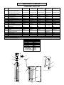
ANALYSIS OF YOUR WATER
Handle the equipment with care. Damage can result if
dropped or if the brine tank is set on sharp, uneven projections on the floor. When handling, do not turn the water
softener unit upside down.
MAKE SURE YOUR WATER HAS BEEN THOROUGHLY
TESTED:
An analysis of your water should be made prior to the
selection of your water conditioning equipment. Your dealer
will generally perform this service for you, and may send a
sample to the factory for analysis and recommendations.
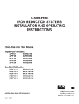
Enter your analysis for a permanent record (see Fig. 1).
Hardness
Iron (Fe)
Manganese (Mn)
pH
Tannins (Humic Acid)
Hydrogen sulfide (H2S)
Other_______________________
Other_______________________
Fig. 1
1-1
______ gpg
______ ppm
______ ppm
______
______ ppm
______ ppm
______
______
CHECK YOUR WATER PRESSURE AND PUMPING RATE:
Two water system conditions must be checked carefully to
avoid unsatisfactory operation or equipment damage:
1) MINIMUM water pressure required at the water softener
inlet is 20 psi (138 kPa). IF PRESSURE IS OVER 100
PSI (689 kPa), A PRESSURE REDUCING VALVE
MUST BE INSTALLED IN THE WATER SUPPLY LINE
AHEAD OF THE WATER SOFTENER.
5) DO NOT install the softener in a location where freezing
temperatures occur. Freezing may cause permanent
damage and will also void the factory warranty.
6) Allow sufficient space around the unit for easy servicing.
7) Provide a non-switched 110/120V, 60Hz power source
for the control.
CAUTION
WARNING
To reduce the risk associated with property
damage due to water leakage:
x
Do not install on systems where line
pressures above 100 psi (689 kPa) may
occur.
To reduce the risk associated with ingestion of
contaminates due to use with water that is
microbiologically unsafe or of unknown quality:
x
NOTE: If you have a municipal or a community water
supply and daytime water pressure is 85 psi (586 kPa)
or more, nighttime pressure may exceed 100 psi (689
kPa). Call your local water department or plant operator
to obtain pressure readings. If you have a private well,
the gauge on the pressure tank will indicate the high
and low system pressure. Record your water pressure
data below:
WATER PRESSURE
Low _______ psi
FACTS TO REMEMBER WHILE PLANNING YOUR INSTALLATION:
(1) All installation procedures MUST conform to local and
state plumbing codes.
(2) If lawn sprinkling, a swimming pool, or geothermal
heating/cooling or water for other devices/activities are
to be treated by the water softener, a larger model MUST
be selected to accommodate the higher flow rate and
softening demand of these items. The pumping rate of
the well pump must be sufficient to accommodate these
items plus the backwashing requirements of the water
softener. Consult your dealer for alternative instructions
if the pumping rate is insufficient.
High _______ psi
CAUTION
To reduce the risk associated with property
damage due to water leakage:
x
Do not use with water that is microbiologically
unsafe or of unknown quality without
adequate disinfection before or after the
system.
Do not install system where water lines that
could be subjected to a vacuum condition
without appropriate measures for vacuum
prevention.
(3) Remember that the water softener INLET is attached to
the pipe that supplies water (i.e., runs to the pump), and
the OUTLET is the line that runs toward the water heater.
The installer should take appropriate measures if there is
the possibility a vacuum may occur. This would include
the installation of an appropriate device in the supply line
to the system, i.e., a vacuum breaker or backflow
prevention device. Vacuum damage voids the factory
warranty.
(4) Before commencing the installation it is advisable to
study the existing piping system and to determine the
size, number and type of fittings required.
NOTE: If the plumbing system is used as the ground leg
of the electrical supply, continuity should be maintained
by installing ground straps around any nonconductive
plastic piping used in installation.
2) The pumping rate of your well pump must be sufficient
for satisfactory operation and BACKWASHING of the
WATER SOFTENER. (see SPECIFICATIONS AND
OPERATING DATA , Section 5).
LOCATE WATER CONDITIONING EQUIPMENT CORRECTLY
Select the location of your water softener with care.
Various conditions which contribute to proper location are
as follows:
(5) It is also advisable to sweep the floor to eliminate
objects that could pierce the brine tank.
IMPORTANT NOTE
(6) SODIUM INFORMATION: Water softeners utilizing
sodium chloride for regeneration add sodium to the
water softened water. Persons who are on sodium
restricted diets should consider the added sodium as
part of their overall sodium intake. As a reference as to
how much sodium is added to softened water consider
the following. For each grain per gallon of water hardness that is exchanged from the water supply, 7.5 milligrams per liter of sodium will be added to the softened
water. e.g. 10 grains per gallon (gpg) exchanged will
add 75 milligrams of sodium to the softened water.
1) Locate as close as possible to water supply source.
2) Locate as close as possible to a floor or laundry tub
drain.
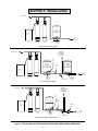
3) Locate in correct relationship to other water conditioning equipment (Figure 1).
4) Locate the softener in the supply line BEFORE the
water heater. Water temperatures above 100°F (38°C)
will damage the softener and void the factory warranty.
1-2
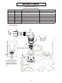
SECTION 2: INSTALLATION
TREATED WATER
PRESSURE
TANK
BRINE
TANK
RAW
WELL
WATER
SOFTENER
FILTER
PRESSURE
SWITCH.
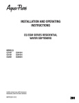
STANDARD WELL INSTALLATION
WATER FOR
LAWN SPRINKLERS
OR OTHER
HIGH DEMAND
TREATED WATER
TO
110 V
OUTPUT
SECONDARY
PRESSURE
PRIMARY
SOLENOID
VALVE
PRESSURE
TANK
TANK
BRINE
TANK
RAW
WELL
WATER
SOFTENER
SECONDARY
PRESSURE
SWITCH.
FILTER
CHECK VALVE
PRIMARY
PRESSURE
SWITCH.
SPLIT-STREAM INSTALLATION
TREATED WATER
WATER FOR
LAWN SPRINKLERS
OR OTHER
HIGH DEMAND
TO
110 V
OUTPUT
PRESSURE
SOLENOID
VALVE
TANK
METER
BRINE
TANK
RAW
WATER
SOFTENER
FILTER
PRESSURE
SWITCH.
CHECK VALVE
PUBLIC WATER SUPPLY INSTALLATION
Figure 1. TYPICAL INSTALLATION SEQUENCE OF WATER CONDITIONING EQUIPMENT
2-1
SECTION 2: INSTALLATION
IMPORTANT: Failure to follow instructions may void warranty.
Step 1. Remove the unit from the shipping box and remove
all packaging. Ensure no freight damage has occurred
since shipment from our manufacturing facility.
Locate the parts package and install the bypass
and adapter fittings on the control valve to facilitate
the connection to the customer’s water supply.
WARNING
To reduce the risk associated with hazardous
voltage due to installation on a home system
that requires use of the cold water system as
a safety ground:
x If the home electrical system requires
use of the cold water system as an
electrical safety ground, a jumper must
be used to ensure the ground connection
across the softener piping — refer
installation to qualified personnel.
CAUTION
To reduce the risk associated with property
damage due to water leakage:
x Do not use pliers or pipe wrenches to
tighten plastic fittings.
Step 2. NOTE: Extension legs should be installed only
whenever a salt dosage on any model softener
is more than 15 lbs.
Models utilizing 15" x 15" x 34" brine tanks require salt grid extension legs when salting the
softener above 15 lbs. of salt or more. Grid legs
extension kits are provided for CWS / MCWS 200
ME units. All other models requiring extension
leg kits can be ordered from your dealer, wholesaler or from CUNO Water Treatment.
Verify all packaging materials have been removed
from the brine tank. On all units, legs rest on bottom
of the brine tank.
Step 3. Shut off all water at main supply valve. On a private
well system, turn off power to pump and drain
pressure tank. Make certain pressure is relieved
from complete system by opening nearest faucet to
drain system.
IMPORTANT NOTE
Step 6. The controls allow for either a 3/4” NPT connection or 5/8” poly tubing for use as a drain line
connection.
CAUTION
To reduce the risk associated with property
damage due to water leakage:
x Do not use pipe sealant on plastic
fittings.
Step 7. Attach DRAIN LINE to DRAIN LINE FITTING. To
prevent back pressure from reducing flow rate below
minimumrequiredforbackwash,DRAINLINEMUST
be sized according to run length and relative height.
Be careful not to bend flexible drain tubing sharply
enough to cause "kinking" (if kinking occurs DRAIN
LINE MUST BE REPLACED). Typical examples of
proper DRAIN LINE diameters are:
x
SHUT OFF FUEL SUPPLY TO WATER
HEATER after water is shut off.
Step 4. Cut main supply line as required to fit plumbing to
INLET and OUTLET of unit.
Step 5. Attach plumbing. DO NOT apply heat to any fitting
connected to BYPASS or CONTROL VALVE as
damage may result to internal parts or connecting
adapters. MAKE CERTAIN WATER FLOW ENTERS
THROUGH INLET AND DISCHARGES THROUGH
OUTLET.
(1) 1/2 in. ID up to 15 ft. when discharge is lower than
INLET.
(2) 5/8 in. ID up to 15 ft. when discharge is slightly
higher than INLET.
(3) 3/4 in. ID when drain is 25 ft. away and/or drain
is installed overhead.
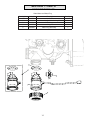
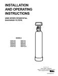
BRINE WELL
BRINE LINE
ELBOW
OUT
IN
BYPASS VALVE
OFF
OFF
OFF
OVERFLOW
FITTING
OFF
SAFETY BRINE
VALVE ASSEMBLY
INJECTOR COVER
CONTROL VALVE BODY
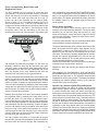
DRAIN LINE FLOW
CONTROL ASSEMBLY
BRINE TANK
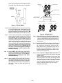
Figure 2. SOFTENER AND BRINE TANK ASSEMBLY, TOP VIEW
2-2
OUT
Some areas prohibit the use of flexible drain lines.
Check with local code officials prior to installation.
IN
BYPASS VALVE
OFF
OFF
OFF
OFF
BRINE LINE
ELBOW
INJECTOR COVER
CONTROL VALVE BODY
DRAIN LINE FLOW
CONTROL ASSEMBLY
Supply Water
Enters
Treated Water
Exits
OFF
OFF
OFF
OFF
Supply Water
Enters
Supply (Untreated)
Water Exits
OFF
OFF
OFF
Figure 3. TYPICAL DRAIN
BYPASS OPERATION
OFF
NORMAL OPERATION
Step 8. Position DRAIN LINE over drain and secure firmly.
To prevent backsiphoning of waste water, provide
an air gap of at least 2 in. or 2 pipe diameters
between end of drain hose and drain (Figure 3). DO
NOT raise DRAIN LINE more than 10 ft. above floor.
Figure 4. BYPASS VALVE
Step 9. Connect one end of the 3/8 in. black Polyethylene
tubing to the brine fitting located on the left side of
the CONTROL VALVE. Connect the other end to
the SAFETY BRINE VALVE ELBOW inside of the
brine well in the brine tank. To do so remove the
retaining clip from the brine line fitting on the control
valve. The retaining clip is holding a plastic insert
sleeve and needs to be inserted into the polyethylene
tubing before installing the tubing into the fitting
elbow and hand tighten only. CAUTION: Do not
use pliers or wrenches to tighten the fitting as
damage may occur and will void the manufacturer’s warranty.
Step 10. Install OVERFLOW LINE to brine tank OVERFLOW FITTING (Figure 2). Discharge of line must
be lower than OVERFLOW FITTING. DO NOT
INTERCONNECT OVERFLOW LINE WITH
VALVE DRAIN LINE.
Step 11. Make certain BYPASS VALVE INLET and OUTLET KNOBS ARE IN "BYPASS" position. After
all plumbing connections have been completed,
open main water shut-off valve or restore power to
well pump. Check for leaks and correct as
necessary.
Step 12. Plug CONTROL VALVE POWER CORD into 120v/
60Hz, non-switched power source. Manually stage
control to BACKWASH POSITION and then unplug power cord to prevent the unit from advancing
automatically.
Step 13. Partially open INLET knob on bypass valve (Figure 4).
This will allow the unit to fill slowly from the bottom
up, reducing air entrapment. Allow unit to fill
slowly, failure to do so could result in loss of resin to
the drain. Once a steady stream of water, no air,
is flowing to drain the inlet and outlet knobs on the
bypass can be fully opened.
Step 14. Refer to Section 3: Regeneration Instructions, on
how to set control valve for proper set up and regeneration settings.
NOTE: Regeneration settings for the control valve
are factory preset. The control valve design permits
adjustment of the salt setting. This adjustment may
be necessary when unusual operating conditions
exist, such as high concentrations of iron, manganese or hardness and/or high flow rates or
daily water consumption.
2-3
Step 15. Refer to SECTION 3, as how to set control
valve for the correct time of day. When shifting
to daylight saving time and (back), you may
wish to adjust TIME OF DAY accordingly.
NOTE: TIME OF REGENERATION is preset for
2:00 a.m. because at this time water consumption
is generally minimal (a built-in hard water bypass
does, however, permit water to be drawn during
regeneration). Should your life style require
regular use of water during the 2:00 to 3:00 a.m.
regeneration period, or if other water treatment
equipment is also set for 2:00 a.m. regeneration,
the TIME OF REGENERATION will need changing. Refer to Section 3, HOW TO SET TIME
OF REGENERATION.
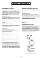
SPECIAL SERVICE INSTRUCTIONS:
Under normal circumstances removal of valve should not
be required. However, if it must be removed, it can be done
by disassembling the quick release clamp, and latch. Pressure should be relieved before attempting any disassembly.
Upon reassembly, all o-rings should belubricated with
silicone grease. Reassemble clamp asshown in Figure 5.
MAKE SURE ARROWS ON LATCHSIDE OF CLAMP
ARE ALIGNED.
Step 16. Before loading salt, using a pail or garden hose,
add enough water to the brine tank to cover the
salt grid (lower shelf on 15" x 15" x 34" brine
tank) at least one (1) inch in depth. Then add
initial salt fill to brine tank, and one (1) cup (eight
ounces) of unscented laundry bleach to the
brine well.
Step 17. Put your new water softener through a complete
regeneration to sanitize the system prior to use.
(Refer to “HOW TO MANUALLY INITIATE THE
CONTROL VALVE” for instructions on manual
regeneration. RESTORE THE FUEL SUPPLY
OR POWER TO THE WATER HEATER”.
Figure 5. CLAMP ASSEMBLY
Installation is now complete, and your water softener is now ready for service. You can expect
many years of virtually trouble free softened water.
If need arises please contact the installing
contractor for immediate attention to your particular issue.
2-4
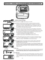
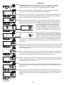
SECTION 3: CONTROL VALVE PROGRAMMING AND REGENERATION
Step 1
Installer Display Settings
(Step 1) Press NEXT and
simultaneously for 3 seconds.
Step 2 (Step 2) Hardness: Set the amount of hardness in grains of hardness as calcium
carbonate per gallon using the or
buttons. The default is 20 with value
ranging from 1 to 150 in 1 grain increments. Note: The grains per gallon can
be increased if soluble iron needs to be reduced. Press NEXT to go to step 3.
Press REGEN to exit Installer Display Settings.
Step 3 (Step 3) Day Override: Day Override sets the number of days between regenerations.
and sets the maximum number of days between regenerations. If value is set
as a number (allowable range from 1 to 28) a regeneration initiation will be called
for on that day even if sufficient number of gallons were not used to call for a
regeneration. Set Day Override using or buttons:
• number of days between regeneration (1 to 28); or “OFF”.
Step 4
Press NEXT to go to step 4. Press REGEN to return to previous step.
(Step 4) Next Regeneration Time (hour): Set the hour of day for regeneration using
or
buttons. AM/PM toggles after 12. The default time is 2:00 a.m. Press
NEXT to go to step 5. Press REGEN to return to previous step.
(Step 5) Next Regeneration Time (minutes): Set the minutes of day for regeneration
Step 5
RETURN TO
NORMAL MODE
using or buttons. Press NEXT to exit Installer Display Settings. Press
REGEN to return to previous step.
To initiate a manual regeneration immediately, press and hold the “REGEN” button
for three seconds. The system will begin to regenerate immediately. The control
valve may be stepped through the various regeneration cycles by pressing the
“REGEN” button.
Power Lost
If power goes out for less than two hours, the system will automatically reset itself.
If an extended power outage occurs, the time of day will flash on and off which indicated the time of day should be reset. The system will remember the rest.
Error Message
If the word "error" and a number are alternately flashing on the display contact the
"Technical Support Services Department at CUNO Water Water Treatment phone
number 1-866-693-2543 for help. This indicates that the valve was not able to function
properly.
3-1
Diagnostics
Step 1 (Step 1) Press or simultaneously for three seconds. If screen in step does not appear in
5 seconds the lock on the valve is activated. To unlock press ,
NEXT, , and SET
CLOCK in sequence, then press NEXT and simultaneously for 3 seconds.
Step 2
(Step 2) Days, since last regeneration: This display shows the days since the last regeneration
occurred. Press the NEXT button. Press REGEN to exit Diagnostics.
(Step 3) Gallons, since last regeneration: This display shows the number of gallons that have been
Step 3
treated since the last regeneration. This display will equal zero if a water meter is not installed.
Press the NEXT button. Press REGEN to return to previous step.
(Step 4) Gallons, reserve capacity used for last 7 days : This display shows 0 day (for today) and
Step 4
flashes the reserve capacity. Pressing the button show day 1 (which would be yesterday)
and flashes the reserve capacity used. Pressing the button again will show day 2 (the
day before yesterday) and reserve capacity. Keep
pressing the button to show the gallons for days 3,
4, 5 and 6. The
button can be pressed to move
backwards in the day series. Press the NEXT button
at any time. Press REGEN to return to previous step.
Step 5 (Step 5) Gallons, 63 day usage history: This display shows day IRU\HVWHUGD\DQGÀDVKHVWKH
number of gallons treated yesterday. Pressing the
button will show day 2 (which would be the day before
yesterday) and flashes the number of gallons treated on
that day. Continue to press the
button to show the
maximum number of gallons treated for the last 63 days. This display will show dashes if a
water meter is not installed. Press the NEXT button at any time. Press REGEN to return to
Step 6
previous step.
(Step 6) )ORZUDWHFXUUHQW7XUQWKHZDWHURQDWRQHRUPRUHWDSVLQWKHEXLOGLQJ7KHÀRZUDWHLQJDOORQV
Step 7
SHUPLQXWHZLOOEHGLVSOD\HG,IÀRZVWRSVWKHYDOXHZLOOIDOOWR]HURLQDIHZVHFRQGV7KLV
display will equal zero if a water meter is not installed. Press the NEXT button. Press REGEN
to return to previous step.
(Step 7) )ORZUDWHPD[LPXPODVWVHYHQGD\V7KHPD[LPXPÀRZUDWHLQJDOORQVSHUPLQXWHWKDWRFF
urred in the last seven days will be displayed. This display will equal zero if a water meter is
not installed. Press the NEXT button. Press REGEN to return to previous step.
Step 8
(Step 8) Gallons, total used since last reset: The total number of gallons used since last reset will be
displayed. This display will equal zero if a water meter is not installed. Press the NEXT button.
Press REGEN to return to previous step.
Step 9 (Step 9) Days, total number since last reset: The total number of days the control valve has been in
service since last reset will be displayed. Press the NEXT button. Press REGEN to return to
previous step.
(Step 10) Regenerations, total number since last reset: The total number of regenerations that have
Step 10
RETURN TO
NORMAL MODE
occurred since last reset will be displayed. Press the NEXT button to exit Diagnostics. Press
REGEN to return to previous step. To lock sttings press , NEXT, , and SET CLOCK in
sequence.
2
Step 1
Valve History
(Step 1) Press
Step 1
Step 2
and simultaneously for three seconds and release. Then press
and
simultaneously and release. If screen, to the left, does not appear
is 5 seconds the lock on the valve is activated. To unlock press , NEXT,
and SET CLOCK in sequence, then press and . Then press
and
simultaneously and release.
(Step 2) Software Version: This display shows the software version of the valve. Press
the NEXT button to go to the next step or press REGEN to exit Valve History.
(Step 3) Flow rate, maximum since startup: This display shows the maximum flow rate
in gallons per minute that has occurred since startup. This display will equal
zero if a water meter is not functioning. Press the NEXT button to go to the
next step. Press REGEN to return to previous step.
Step 3
(Step 4) Gallons, total used since start-up: This display shows the total gallons. This
display shows the total days since startup. Press the NEXT button to go to the
next step. Press REGEN to return to previous step.
(Step 5) Days, total since start-up: This display shows the total days since startup. Press
the NEXT button to go to the next step. Press REGEN to return to previous step.
Step 4 (Step 6)
Regenerations, total number since start-up: This display shows the total number
of regenerations that have occurred since startup. Press the NEXT button to
go to the next step. Press REGEN to return to previous step.
(Step 7) Error, number of occurrences since start-up: This display shows E and the
Step 5
total number of errors that have occurred since startup. Press the NEXT button
to exit Valve History. Press REGEN to return to previous step. To lock settings
press ,NEXT, , and SET CLOCK in sequence.
Step 6
Step 7
RETURN TO
NORMAL MODE
3-3
User Display Settings
General Operation
When the system is operating, one of two displays
will be shown. Pressing NEXT will alternate between
the displays. One of the displays is always the current time of day. The second display is one of the
following: days remaining or gallons remaining. Days
remaining is the number of days left before the system goes through a regeneration cycle. Capacity
remaining is the number of gallons that will be treated
before the system goes through a regeneration cycle.
The user can scroll between the displays as desired.
If the system has called for a regeneration that will
occur at the prest time of regeneration, the words
“REGEN TODAY” will appear on the display.
OR
REGEN TODAY will be
displayed if a regeneration
is expected “Tonight.”
When water is being treated (i.e. water is flowing through the system) the word “SOFTENING” flashes on the display
if a water meter is installed.
Regeneration Mode
Typically a system is set to regenerate at a time of low
water usage. An example of a time with low water usage
is when members of a household are asleep. If there is a
demand for water when the system is regenerating, untreated water will be used.
When the system begins to regenerate, the display will change to include information about the step of the regeneration
process and the time remaining for that step to be completed. The system runs through the steps automatically and will
reset itself to help provide treated water when the regeneration has been completed.
Manual Regeneration
REGEN TODAY will
Flash if a regeneration
is expected “Tonight.”
Sometimes there is a need to regenerate the system
sooner than when the system calls for it, usually referred
to as manual regeneration. There may be a period of heavy
water usage because of guests or a heavy laundry day.
To initiate a manual regeneration at the present delayed regeneraton
time, press and release “REGEN”. The words “REGEN TODAY” will flash on the display to indicate that the
system will regenerate at the preset delayed regeneration time.
NOTE: If you pressed the "REGEN" button in error, pressing the button again will cancel the request.
To initiate a manual regeneration immediately, press and hold the “REGEN” button for three seconds. The system will begin
to regenerate immediately. The request cannot be cancelled.
NOTE: For softeners, if brine tank does not contain salt, fill with salt and wait at least two hours before regenerating.
Set Time of Day
The user can also set the time of day. Time should only need
to be set after extended power outages or when daylight saving
time begins or ends. If an extended power outage occurs, the
time of day will flash on and off which indicates the time of day
should be reset.
Step 1 - Press SET CLOCK.
Step 2 - Current Time (hour): Set the hour of the day using
or button. AM/PM toggles after 12. Press NEXT to go to step 3.
Step 3 - Current Time (minutes): Set the minutes of the day
using or
buttons. Press NEXT to exit Set Clock. Press
“REGEN” to return to previous step.
3-4
SECTION 4: MAINTENANCE
REPLENISHMENT OF SALT SUPPLY:
PERIODICALLY CHECK TIME OF DAY SETTING:
The salt storage capacity of the brine tank is approximately
180 lbs (82 kg). During each regeneration a specific amount
of salt is consumed, thus requiring its periodic replenishment (the frequency and salt dosage level is dependent
on the regeneration schedule). Always replenish salt
before the supply is exhausted for a continuous supply
of softened water.
Power outages will cause “TIME OF DAY” setting to
become incorrect. To correct, refer to Section 4 on how
to correct.
MALFUNCTION OF UNIT:
Your water softener, under normal conditions, should provide years of virtually trouble-free service; however, since
it is a mechanical device, it can malfunction. (Refer to
Section 5, SERVICE INSTRUCTIONS, if necessary).
TYPE OF SALT TO USE:
Any type of water softener salt may be used. There are
advantages and disadvantages to every type of salt.
Please ask your local dealer for his advice. Your unit is
designed to compensate for the disadvantages. However
the use of block salt is not encouraged due to its possible problems in making enough brine for regeneration
purposes.
CHANGE OF OPERATING CONDITIONS:
Should your family size, your water usage habits, or your
water quality change, the regeneration program settings
may have to be adjusted. Consult your dealer if any of the
above occur.
BRINE TANK CLEAN-OUT:
SPECIAL SERVICE INSTRUCTIONS:
To prevent service problems the brine tank should be
emptied and flushed out with a garden hose when dirt and
other insolubles accumulate.
Under normal circumstances, removal of valve should
never be required. However, if it must be removed, it can
be done by disassembling the quick release clamp, by
removing latch. Pressure should be relieved before attempting any disassembly. Upon reassembly, all o-rings
should be lubricated with silicone grease. Reassemble
clamp as shown in Figure 6. MAKE SURE ARROWS ON
LATCH SIDE OF CLAMP ARE ALIGNED.
Steps to follow:
(1) Disconnect brine line at either end.
(2) Turn brine tank upside down and discard old salt.
(3) Rinse out with a garden hose.
(4) Reconnect brine line.
(5) Before loading salt, using a pail or garden hose add
enough water to the brine tank to cover the salt grid lower
shelf on 15” x 15” x 34” brine tank at least one (1) inch in
depth. Then add initial salt to brine tank and add one (1)
cup of unscented laundry bleach to the brine well.
(6) Perform approximately once a year if rock salt is
used; with other types of salt, approximately once every
other year.
PREVENTING IRON-FOULING OF MINERAL BED:
If iron is present in the water supply, the softener mineral
bed will eventually become iron-fouled, resulting in reduced
softening capacity and rust-stained fixtures. Mixing one to
two ounces of IRON-X Mineral Cleaner with every 80 lbs.
of salt added to brine tank will help minimize these problems from occurring. IRON-X is available from your dealer.
Figure 6. CLAMP ASSEMBLY
4-1
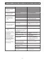
SECTION 5: CONTROL VALVE TROUBLESHOOTING GUIDE
Pr obl em
Possi bl e Cause
a. AC Adapter unplugged
1. Timer does not display
time of day
2. Timer does not display
correct time of day
3. No softening/ ¿ ltering
display when water is
À owing
4. Control valve regenerates
at wrong time of day
5.
ERROR followed by code
number
Error Code 1001 -Unable to
recognize start of regeneration
Error Code 1002 –
Unexpected stall
Error Code 1003 – Motor ran
too long, timed out trying to
reach next cycle position
Error Code 1004 - Motor ran
too long, timed out trying to
reach home position
If other Error Codes display
contact the factory.
Sol ut i on
a. Connect power
b. No electric power at outlet
b. Repair outlet or use working outlet
c. Defective AC Adapter
c. Replace AC Adapter
d. Defective PC board
d. Replace PC board
a. Switched outlet.
a Use uninterrupted outlet
b. Power outage
b. Reset time of day
c. Defective PC board
c. Replace PC board
a. Bypass valve in bypass position
b. Meter connection disconnected
a. Put bypass valve in service position
b. Connect meter to PC board
c. Restricted/stalled meter turbine
c. Remove meter and check for
rotation or foreign material.
d. Defective meter
d. Replace meter
e. Defective PC board
e. Replace PC board
a. Power outages
a. Reset control valve to correct time
of day
b. Time of day not set correctly
b. Reset to correct time of day
c. Time of regeneration incorrect
c. Reset regeneration time
a. Control valve has just been serviced
or unplug power source jack (black
wire) and plug back in to reset
control valve
a. Press NEXT and REGEN for 3 seconds
b. Foreign matter is lodged in control
valve
b. Check piston and spacer stack
assembly
c. High drive forces on piston
c. Replace piston(s) and spacer
stack assembly
d. Control valve piston not in home
position seconds
d. Press NEXT and REGEN for 3
seconds or unplug power source
jack (black wire) and plug back in
to reset control valve
e. Motor not inserted fully to engage
pinion, motor wires broken or
disconnected, motor failure
e. Check motor and wiring.
Replace motor if necessary
f. Drive gear label dirty or damaged,
missing or broken gear
f. Replace or clean drive gear
g. Drive bracket incorrectly aligned
to back plate
g. Reseat drive bracket properly
h. PC board is damaged or defective
h. Replace PC board
i. PC board incorrectly aligned to
drive bracket
i. Ensure PC board is correctly snapped
on to drive bracket
5-1
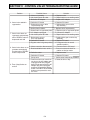
SECTION 5: CONTROL VALVE TROUBLESHOOTING GUIDE
Problem
6. Control valve stalled in
regeneration
Possible Cause
a. Motor not operating
b. No electric power at outlet
c. Defective AC Adapter
d. Defective PC board
Solution
a. Replace motor
b. Repair outlet or use working outlet
c. Replace AC Adapter
d. Replace PC board
e. Broken drive gear or drive
cap assembly cap
e. Replace drive gear or drive
cap assembly
f. Broken piston retainer
f. Replace drive cap assembly
g. Broken main or regenerant piston
a. AC Adapter unplugged
b. No electric power at outlet
g. Replace main or regenerant piston
a. Connect AC Adapter
b. Repair outlet or use working outlet
7. Control valve does not
regenerate automatically
when “REGEN” button is c. Broken drive gear or
drive cap assembly
depressed and held
d. Defective PC board
a. By-pass valve in bypass position
8. Control valve does not re- b. Meter connection disconnected
c. Restricted/stalled meter turbine
generate automatically
but does when “REGEN”
button is depressed
d. Defective meter
e. Defective PC board
f. Set-up error
9. Time of day À ashes on
and off
a. Power has been out more than
two hours, the AC Adapter was
unplugged and then plugged
back into the wall outlet, the AC
Adapter plug was unplugged
and then plugged back into the
board or the NEXT and REGEN
buttons were pressed to reset
the valve.
5-2
c. Replace drive gear or drive cap
assembly
d. Replace PC board
a. Put bypass valve in normal
operation position
b. Connect meter to PC board
c. Remove meter and check for
rotation or foreign matter
d. Replace meter
e. Replace PC board
f. Check control valve set-up prodedure
a. Reset the time of day
SECTION 5: CONTROL VALVE SERVICE INSTRUCTIONS
Drive Assembly
Remove the valve cover to access the drive assembly.
WARNING: Disconnect the power source plug (black wire)
from the PC board prior to disconnecting the motor or water
meter plugs from the PC board. The power source plug
connects to the four-pin jack. The motor plug connects to the
two-pin jack on the left-hand side of the PC board. The water
meter plug (grey wire) connects to the three-pin jack on the far
right-hand side of the PC board.
The PC board can be removed separately from the drive
bracket but it is not recommended. Do not attempt to remove
the display panel from the PC board. Handle the board by the
edges. To remove the PC board from the drive bracket,
unplug the power, water meter and motor plugs from the PC
board. Lift the middle latch along the top of the drive bracket
while pulling outward on the top of the PC board. The drive
EUDFNHWKDVWZRSODVWLFSLQVWKDW¿WLQWRWKHKROHVRQWKHORZHU
edge of the PC board. Once the PC board is tilted about 45°
from the drive bracket it can be lifted off of these pins. To
reinstall the PC board, position the lower edge of the PC
board so that the holes in the PC board line up with the
plastic pins. Push the top of the PC board towards the valve
until it snaps under the middle latch, weave the power and
water meter wires into the holders and reconnect the motor,
water meter and power plugs.
The drive bracket must be removed to access the drive cap
assembly and pistons or the drive gear cover. It is not necessary to remove the PC board from the drive bracket to
remove the drive bracket. To remove the drive bracket, start
by removing the plugs for the power source and the water
meter. Unweave the wires from the side holders. Two tabs on
the top of the drive back plate hold the drive bracket in place.
Simultaneously lift the two tabs and gently ease the top of the
drive bracket forward.The lower edge of the drive bracket
has two notches that rest on the back plate. Lift up and
outward on the drive bracket to disengage the notches.
To reassemble, seat the bottom of the drive bracket so the
notches are engaged at the bottom of the drive back plate.
Push the top of the drive bracket toward the two latches. The
drive bracket may have to be lifted slightly to let the threaded
piston rod pass through the hole in the drive bracket. Maintain a slight engaging force on top of the drive bracket while
GHÀHFWLQJWKHEUDFNHWVOLJKWO\WRWKHOHIWE\SUHVVLQJRQWKH
side of the upper right corner. This helps the drive gears
mesh with the drive cap assembly. The drive bracket is properly seated when it snaps under the latches on the drive back
plate. If resistance is felt before latching, then notches are
not fully engaged, the piston rod is not in hole, the wires are
jammed between the drivebracket and drive back plate, or
the gear is not engaging the drive cap assembly. To inspect
the drive gears, the drive gear cover needs to be removed.
Before trying to remove the gear cover, the drive bracket
must be removed from the drive back plate. (Refer to the
5-3
proceeding instructions regarding removing the drive bracket
from the drive backplate. The drive gear cover can be
removed from the drive bracket without removing the motor
or the PC board.) The drive gear cover is held in place on the
drive bracket by three clips. The largest of the three clips is
always orientated to the bottom of the drive bracket. With the
PC board facing up, push in and down on the large clip on the
drive gear cover. Handle the cover and the gears carefully so
that the gears do not fall off of the pegs in the cover.
Replace broken or damaged drive gears. Do not lubricate
any of the gears. Avoid getting any foreign matter on the
UHÀHFWLYH FRDWLQJ EHFDXVH GLUW RU RLOV PD\ LQWHUIHUH ZLWK
pulse counting.
The drive gear cover only fits on one way, with the large clip
orientated towards the bottom. If all three clips are outside of
the gear shroud on the drive bracket the drive gear cover
slips easily into place.
The drive bracket does not need to be removed from the
drive plate if the motor needs to be removed. To remove the
motor,disconnect the power and motor plugs from the jacks
on the PC board. Move the spring clip loop to the right and
hold. Rotate the motor at least a ¼ turn in either direction so
the wires are vertical (up & down) before gently pulling on
the wire connectors to remove the motor. Pulling directly on
the wires without rotating the motor may break the wires off
the motor.
Replace the motor if necessary. Do not lubricate the motor or
the gears. To reinstall the motor, move the spring clip loop to
the right and hold. Gently turn the motor while inserting so
that the gear on the motor meshes with the gears under the
drive gear cover. Release the spring clip loop and continue
to rotate the motor until the wires are horizontal and the
motor housing engages the small plastic bulge inside the
drive bracket motor retainer. Reconnect the motor plug to
the two-pronged jack on the lower left hand side of the PC
board. If the motor will not easily engage with the drive gears
when reinstalling, lift and slightly rotate the motor before
reinserting. Reconnect the power.
Replace the valve cover. After completing any valve maintenance, press and hold NEXT and REGEN buttons for 3
seconds or unplug power source jack (black wire) and plug
back in. This resets the electronics and establishes the
VHUYLFHSLVWRQSRVLWLRQ7KHGLVSOD\VKRXOGÀDVKDOOZRUGLQJ
WKHQÀDVKWKHVRIWZDUHYHUVLRQHJDQGWKHQUHVHWWKH
valve to the service position.
Drive Cap Assembly, Main Piston and
Regenerant Piston
The drive assembly must be removed to access the drive
cap assembly. The drive cap assembly must be removed to
access the piston(s). The drive cap assembly is threaded
into the control valve body and seals with an o-ring. To
remove the drive cap assembly use the special plastic
ZUHQFKRULQVHUWDó´WRò´ÀDWEODGHVFUHZGULYHULQWRRQHRI
WKH VORWV DURXQG WKH WRS ´ RI WKH GULYH FDS DVVHPEO\ VR LW
engages the notches molded into the drive back plate around
´RIWKHSLVWRQFDYLWy. See Figure 7. The notches are visible
through the holes. Lever the screwdriver so the drive cap
DVVHPEO\WXUQVWRWKHOHIW2QFHORRVHQHGXQVFUHZthe drive
YDOYHPDLQWHQDQFHSUHVVDQGKROG1(;7DQG5(*(1EXWWRQV
IRUVHFRQGVRUXQSOXJSRZHUVRXUFHMDFNEODFNZLUHDQGSOXJ
back in. This resets the electronics and establishes the service
SLVWRQSRVLWLRQ7KHGLVSOD\VKRXOGÀDVKDOOZRUGLQJWKHQÀDVK
WKHVRIWZDUHYHUVLRQHJDQGWKHQUHVHWWKHYDOYHWRWKH
service position.
Spacer Stack Assembly
To access the spacer stack assembly remove the drive
assePEO\GULYHFDSDVVHPEO\DQGSLVWRQ7KHVSDFHUVWDFN
assembly can be removed easily without tools by using
WKXPEDQGIRUHILQJHU,QVSHFWWKHEODFNRULQJVDQGFOHDUOLS
VHDOVIRUZHDURUGDPDJH5HSODFHWKHHQWLUHVWDFNLIQHFHVVDU\'RQRWGLVDVVHPEOH
The spacer stack assembly may be chemically cleaned (dilute
VRGLXPELVXO¿WHRUYLQHJDURUZLSHGZLWKDVRIWFORWK
Figure 7
cap assembly by hand and pull straight out. The drive cap
DVVHPEO\ FRQWDLQV WKH GULYH FDS WKH PDLQ GULYH JHDU GULYH
FDSVSOLQHSLVWRQURGDQGYDULRXVRWKHUSDUWVWKDWVKRXOGQRW
EHGLVVHPEOHGLQWKH¿HOG7KHRQO\UHSODFHDEOHSDUWRQWKH
drive cap assembly is the o-ring. Attached to the drive cap
assembly is the main piston and a regenerant piston.
The regenerant piston (the small diameter one behind the main
SLVWRQLVUHPRYHGIURPWKHPDLQSLVWRQE\SUHVVLQJVLGHZD\V
DQG XQVQDSSLQJ LW IURP LWV ODWFK &KHPLFDOO\ FOHDQ LQ GLOXWH
VRGLXPRUYLQHJDURUUHSODFHWKHUHJHQHUDQWSLVWRQLIQHHGHG
7RUHPRYHWKHPDLQSLVWRQIXOO\H[WHQGWKHSLVWRQURGDQGWKHQ
XQVQDSWKHPDLQSLVWRQIURPLWVODWFKE\SUHVVLQJRQWKHVLGH
ZLWKWKHQXPEHU&KHPLFDOO\FOHDQLQGLOXWHVRGLXPELVXOILWHRU
YLQHJDURUUHSODFHWKHPDLQSLVWRQ
Reattach the main piston to the drive cap assembly. Reattach
WKHUHJHQHUDQWSLVWRQLIQHHGHGWRWKHPDLQSLVWRQ'RQRW
OXEULFDWH WKH SLVWRQ URG PDLQ SLVWRQ RU UHJHQHUDQW SLVWRQ
/XEULFDQWZLOODGYHUVHO\DIIHFWWKHFOHDUOLSVHDOV5HLQVHUWWKH
drive cap assembly and piston into the spacer stack assembly
DQGKDQGWLJKWHQWKHGULYHFDSDVVHPEO\&RQWLQXHWRWLJKWHQ
the drive cap assembly using a screwdriver as a ratchet until
the black o-ring on the spacer stack assembly is no longer
YLVLEOHWKURXJKWKHGUDLQSRUW([FHVVLYHIRUFHFDQbreak the
notches molded into the drive back plate. Make certain that
WKHPDLQGULYHJHDUVWLOOWXUQVIUHHOy.
7KHH[DFWSRVLWLRQRIWKHSLVWRQLVQRWLPSRUWDQWDVORQJDV
tKHPDLQGULYHJHDUWXUQVIUHHO\5HDWWDFKWKHGULYHDVVHPEO\WR
WKH FRQWURO YDOYH DQG FRQQHFW DOO SOXJV $IWHU FRPSOHWLQJ DQ\
5-4
The spacer stack assembly can be pushed in to the control valve
body bore by hand. Since the spacer stack assembly can be
FRPSUHVVHGLWLVHDVLHUWRXVHDEOXQWREMHFW´WR´LQ
GLDPHWHU WR SXVK WKH FHQWHU RI WKH DVVHPEO\ LQWR WKH FRQWURO
YDOYHERG\7KHDVVHPEO\LVSURSHUO\VHDWHGZKHQDWOHDVWIRXU
WKUHDGV DUH H[SRVHG DSSUR[LPDWHO\ ´ 'R QRW IRUFH WKH
spacer stack assembly in. The control valve body bore interior
FDQEHOXEULFDWHGZLWKVLOLFRQHWRDOORZIRUHDV\
LQVHUWLRQRIWKHHQWLUHVWDFN'RQRWXVHVLOLFRQHRUDQ\RWKHUW\SH
RIOXEULFDQWRQWKHFOHDUOLSVHDOVRUWKHSLVWRQ
Reattach the drive cap assembly and piston(s) and the drive
assembly.
$IWHUFRPSOHWLQJDQ\YDOYHPDLQWHQDQFHSUHVVDQGKROG1(;7
DQG5(*(1EXWWRQVIRUVHFRQGVRUXQSOXJSRZHUVRXUFHMDFN
(black wire) and plug back in. This resets the electronics and
HVWDEOLVKHVWKHVHUYLFHSLVWRQSRVLWLRQ7KHGLVSOD\VKRXOGÀDVK
DOOZRUGLQJWKHQÀDVKWKHVRIWZDUHYHUVLRQHJDQGWKHQ
reset the valve to the service position.
Injector Cap, Screen, Injector Plug and Injector
8QVFUHZ WKH LQMHFWRU FDS DQG OLIW RII /RRVHQ FDS ZLWK VSHFLDO
SODVWLFZUHQFKRUSOLHUVLIQHFHVVDU\$WWDFKHGWRWKHLQMHFWRUFDS
LV D VFUHHQ 5HPRYH WKH VFUHHQ DQG FOHDQ LI IRXOHG7KH SOXJ
DQGRULQMHFWRUFDQEHSULHGRXWZLWKDVPDOOVFUHZGULYHU7KHSOXJ
FDQEHZLSHGFOHDQ,IWKHSOXJOHDNVUHSODFHWKHHQWLUHSOXJ7KH
LQMHFWRUFRQVLVWVRIDWKURDWDQGDQR]]OH&KHPLFDOO\FOHDQWKH
LQMHFWRUZLWKYLQHJDURUVRGLXPELVXO¿WH7KHKROHVFDQEHEORZQ
out with air. Both pieces have small diameter holes that control
WKHÀRZUDWHVRIZDWHUWRLQVXUHWKDWWKHSURSHUFRQFHQWUDWLRQRI
UHJHQHUDQWLVXVHG6KDUSREMHFWVZKLFKFDQVFRUHWKHSODVWLF
VKRXOGQRWEHXVHGWRFOHDQWKHLQMHFWRU6FRULQJWKHLQMHFWRURU
LQFUHDVLQJWKHGLDPHWHURIWKHKROHFRXOGFKDQJHWKHRSHUDWLQJ
SDUDPHWHUVRIWKHLQMHFWRU3XVKWKHSOXJVDQGRULQMHFWRUVILUPO\
LQSODFHUHSODFHWKHVFUHHQDQGKDQGWLJKWHQWKHLQMHFWRUFDS
5H¿OO)ORZ&RQWURO$VVHPEO\RU5H¿OO3RUW3OXJ
TRFOHDQRUUHSODFHWKHUH¿OOÀRZFRQWUROSXOORXWWKHHOERZORFNLQJFOLSDQGWKHQSXOOVWUDLJKWXSRQWKHHOERZ. Replace
WKHHOERZORFNLQJFOLSLQWKHVORWVRWKDWLWLVQRWPLVSODFHG7ZLVWWRUHPRYHWKHZKLWHÀRZFRQWUROUHWDLQHU7KHÀRZFRQWURO
FDQEHUHPRYHGE\SU\LQJXSZDUGWKURXJKWKHVLGHVORWVRIWKHUHWDLQHUZLWKDVPDOOÀDWEODGHVFUHZGULYHr.
&KHPLFDOO\FOHDQWKHÀRZFRQWURORUWKHZKLWHÀRZFRQWUROUHWDLQHUXVLQJGLOXWHVRGLXPELVXO¿WHRUYLQHJDU'RQRWXVH a
ZLUHEUXVK,IQHFHVVDU\UHSODFHWKHÀRZFRQWURORULQJRQWKHÀRZFRQWUROUHWDLQHrRUWKHRULQJRQWKHHOERZ.
5HVHDWWKHÀRZFRQWUROVRWKHURXQGHGHQGLVYLVLEOHLQWKHÀRZFRQWURO5HVHDWWKHZKLWHÀRZFRQWUROUHWDLQHUE\SXVKLQJ
WKHUHWDLQHULQWRWKHHOERZXQWLOWKHRULQJVHDWV5HPRYHORFNLQJFOLSSXVKGRZQRQHOERZWRUHVHDWDQGLQVHUWORFNLQJFOLS
'RQRWXVH9DVHOLQHRLOVRURWKHUXQDFFHSWDEOHOXEULFDQWVRQRULQJV$VLOLFRQHOXEULFDQWPD\EHXVHGRQWKHRULQJRQWKH
HOERZRUWKHZKLWHUHWDLQHr.
WDWHU0HWHURU0HWHU3OXJ
7KHZDWHUPHWHUDVVHPEO\LVFRQQHFWHGWRWKH3&ERDUGE\DZLUH,IWKHHQWLUHZDWHUPHWHUDVVHPEO\LVWREHUHSODFHG
UHPRYHWKHFRQWUROYDOYHFRYHUDQGGLVFRQQHFWWKHSRZHUVRXUFHDQGZDWHUPHWHUSOXJVIURPWKH3&ERDUG8QODWFKWKH
GULYHDVVHPEO\DQGOHDQLWIRUZDUG8QWKUHDGWKHZDWHUPHWHUZLUHIURPWKHVLGHRIWKHGULYHDVVHPEO\DQGWKURXJKWKH
GULYHEDFNSODWH7RUHLQVWDOOUHWKUHDGWKHZDWHUPHWHUZLUHWKURXJKWKHGULYHEDFNSODWHDQGWKHVLGHRIWKHGULYHDVVHPEO\
5HDWWDFKWKHGULYHDVVHPEO\DQGWKHZDWHUPHWHUDQGSRZHUSOXJV,IQRZDWHUPHWHUZLUHLVYLVLEOHWKHQDSOXJLVLQVWDOOHG
QRWDZDWHUPHWHU7KHZDWHUPHWHUZLUHGRHVQRWQHHGWREHUHPRYHGIURPWKH3&ERDUGLIWKHZDWHUPHWHULVRQO\EHLQJ
LQVSHFWHGDQGFOHDQHG7RUHPRYHWKHZDWHUPHWHUDVVHPEO\XQVFUHZWKHPHWHUFDSRQWKHOHIWVLGHRIWKHFRQWUROYDOYH
3OLHUVPD\EHXVHGWRXQVFUHZWKHQXWLIQHFHVVDU\. WLWKWKHQXWUHPRYHGDVORWDWWKHWRSRIWKHZDWHUPHWHULVYLVLEOH
7ZLVWDÀDWEODGHVFUHZGULYHULQWKHVORWEHWZHHQWKHFRQWUROYDOYHERG\DQGWKHPHWHU:KHQWKHPHWHULVSDUWZD\RXWLW
LVHDV\WRUHPRYHWKHZDWHUPHWHUIURPWKHKRXVLQJ2QFHWKHZDWHUPHWHULVUHPRYHGIURPWKHFRQWUROYDOYHERG\JHQWO\
SXOOIRUZDUGRQWKHWXUELQHWRUHPRYHLWIURPWKHVKDIW
'RQRWXVHDZLUHEUXVKWRFOHDQWKHWXUELQH:LSHZLWKDFOHDQFORWKRUFKHPLFDOO\FOHDQLQGLOXWHVRGLXPELVXO¿WHRU
YLQHJDU7KHWXUELQHFDQEHLPPHUVHGLQWKHFKHPLFDO'RQRWLPPHUVHHOHFWURQLFV,IWKHWXUELQHLVVFRUHGRUGDP
DJHGRUWKHEHDULQJRQWKHWXUELQHDUHZRUQUHSODFHWKHWXUELQH
'RQRWOXEULFDWHWKHWXUELQHVKDIW7KHWXUELQHVKDIWEHDULQJVDUHSUHOXEULFDWHG'RQRWXVH9DVHOLQHRLOVRURWKHU
XQDFFHSWDEOHOXEULFDQWVRQWKHRULQJ$VLOLFRQHOXEULFDQWPD\EHXVHGRQWKHEODFNRULQJ
6QDSWKHWXUELQHRQWKHVKDIWDQGUHLQVHUWWKHZDWHUPHWHULQWRWKHVLGHVORW+DQGWLJKWHQWKHQXW'RQRWXVHDSLSH
ZUHQFKWRWLJKWHQQXW
%\SDVVVDOYH
7KHZRUNLQJSDUWVRIWKHE\SDVVYDOYHDUHWKHURWRUDVVHPEOLHVWKDWDUHFRQWDLQHGXQGHUWKHE\SDVVYDOYHFDSV%HIRUH
ZRUNLQJRQWKHURWRUVPDNHVXUHWKHV\VWHPLVGHSUHVVXUL]HG TXUQWKHUHGDUURZVKDSHGKDQGOHVWRZDUGVWKHFHQWHURI
WKHE\SDVVYDOYHDQGEDFNVHYHUDOWLPHVWRHQVXUHURWRULVWXUQLQJIUHHO\.
7KHQXWVDQGFDSVDUHGHVLJQHGWREHXQVFUHZHGRUWLJKWHQHGE\KDQG,IQHFHVVDU\DSOLHUVFDQEHXVHGWRXQVFUHZWKH
QXWRUFDS'RQRWXVHDSLSHZUHQFKWRWLJKWHQRUORRVHQQXWVRUFDSV'RQRWSODFHVFUHZGULYHULQVORWVRQFDSVDQGRU
WDSZLWKDKDPPHr. TRDFFHVVWKHURWRrXQVFUHZWKHFDSDQGOLIWWKHFDSURWRUDQGKDQGOHRXWDVRQHXQLW TZLVWLQJWKH
XQLWDV\RXSXOOLWRXWZLOOKHOSWRUHPRYHLWPRUHHDVLO\7KHUHDUHWKUHHRULQJVRQHXQGHUWKHURWRUFDSRQHRQWKHURWRU
VWHPDQGWKHURWRUVHDO5HSODFHZRUQRULQJV&OHDQURWRr5HLQVWDOOURWRr.
:KHQUHLQVWDOOLQJWKHUHGDUURZKDQGOHVEHVXUHWKDW
1. 7KHKDQGOHSRLQWHUVDUHOLQHGXSZLWKWKHFRQWUROYDOYHERG\DUURZVDQGWKHURWRUVHDORULQJDQGUHWDLQHURQ
ERWKURWRUVIDFHWRWKHULJKWZKHQEHLQJYLHZHGIURPWKHIURQWRIWKHFRQWUROYDOYHRU
2. $UURZVSRLQWWRZDUGHDFKRWKHULQWKHE\SDVVSRVLWLRQ
6LQFHWKHKDQGOHVFDQEHSXOOHGRIIWKH\FRXOGEHDFFLGHQWDOO\UHLQVWDOOHGIURPWKHLUFRUUHFWRULHQWDWLRQ7RLQVWDOO
WKHUHGDUURZKDQGOHVFRUUHFWO\NHHSWKHKDQGOHVSRLQWHGLQWKHVDPHGLUHFWLRQDVWKHDUURZVHQJUDYHGRQWKHFRQWURO
YDOYHERG\ZKLOHWLJKWHQLQJWKHE\SDVVYDOYHFDSV$IWHUFRPSOHWLQJDQ\YDOYHPDLQWHQDQFHSUHVVDQGKROG1(;TDQG
5(*(1EXWWRQVIRUVHFRQGVRUXQSOXJSRZHUVRXUFHMDFNEODFNZLUHDQGSOXJEDFNLQ 7KLVUHVHWVWKHHOHFWURQLFV
DQGHVWDEOLVKHVWKHVHUYLFHSLVWRQSRVLWLRQ 7KHGLVSOD\VKRXOGÀDVKDOOZRUGLQJWKHQÀDVKWKHVRIWZDUHYHUVLRQ
HJDQGWKHQUHVHWWKHYDOYHWRWKHVHUYLFHSRVLWLRQ
SECTION 5: SYSTEM TROUBLESHOOTING GUIDE
PROBLEM
1.
CAUSE
SOLUTION
Hard water, (unit not
using salt; liquid level
in brine tank not too
high)
A.
Electrical service to unit interrupted.
A.
B.
C.
D.
Time improperly set.
Safety brine valve not opening.
Salt "bridged" in brine tank.
B.
C.
D.
Assure permanent electrical service (check fuse, plug, pull chain
or switch.)
Check programming function.
Replace safety brine valve.
Breakup salt.
2.
Hard water, (unit
using salt; liquid level
in brine tank not
too high).
A.
B.
C.
D.
E.
F.
Bypass open.
Valve programming incorrect.
No salt in brine tank.
Excessive water usage.
Unit installed backwards.
Unit undersized.
A.
B.
C.
D.
E.
F.
Close bypass (replace if necessary).
Check valve programming.
Add salt; maintain above water level.
Check programming function.
Reinstall unit.
Replace with larger unit.
3.
Liquid level in brine
tank TOO high.
A.
B.
C.
D.
Regenerant piston failure.
Salt setting too high.
Injector screen plugged.
Drain line frozen, plugged or restricted.
Salt "mushed" or sand from salt
plugging bottom of brine tank.
Incorrect brine line flow control
(BLFC).
A.
B.
C.
D.
Inspect regenerant piston.
Reset timer.
Clean injector and screen.
Free drain.
E.
Clean out brine tank (see instructions).
F.
Replace with correct flow control (See specifications).
A.
Foreign material in control valve.
A.
B.
C.
Internal control leak.
Control valve jammed in brine or
backwash position.
B.
C.
Remove piston assembly and inspect bore; remove foreign
material and check control in various regeneration positions.
Replace seals and/or piston assembly.
Replace piston, seals and spacers.
A.
Salt setting too high.
A.
Check salt setting.
B.
Cyclone (distributor) tube too short.
B.
Replace.
E.
F.
5.
6.
Water continuously
flows to drain.
Water tastes salty.
7.
White spots on
glassware and dark
surfaces.
A.
Sodium residual resulting from water having very high hardness or
total dissolved solids (TDS).
A.
Installation of additional water treatment equipment such as reverse osmosis or demineralization.
8.
Low water pressure
(low flow rate).
A.
A.
Clean line to water conditioner.
B.
Iron build-up in line to water conditioner.
Iron build-up in water conditioner.
B.
C.
D.
Well pumping sand.
Pump losing capacity.
C.
D.
Clean control and add Iron-X Mineral Cleaner to resin bed; increase
frequency of regeneration.
Install sand trap.
Contact pump repair service.
9. "Rotten egg" smell
(from hot water
ONLY ).
A.
Magnesium rod in water heater.
A.
Replace with aluminum rod or remove.
10. "Rotten egg" smell
(from both hot and
cold water).
A.
A.
Install Sul-X Sulfur Reduction System.
B.
C.
Hydrogen sulfide ("sulfur") in water
supply.
Bacterial iron in water supply.
Algae in water supply.
B.
C.
Install Chem-Free Iron Reduction System.
Pour approximately 1/2 cup laundry bleach into brine well just
before regeneration as frequently as necessary.
11. Loss of resin through
drain line.
A.
Air in water system.
A.
Assure that well system has proper air eliminator control; check
for dry well condition.
5-5
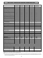
SECTION 6: SPECIFICATIONS AND OPERATING DATA
ITEM
Nominal Media Volume, Ft 3
Salt Dosage, Lbs.
Salt Efficient Setting
Factory Setting
Maximum Setting
Softening Capacity, grains
At Salt Efficient Setting
At Factory Salt Setting
At Maximum Salt Setting
Salt Efficiency, grains per lb. of salt
At Salt Efficient Setting
Flow Rates
Continuous (no duration limit)
At 15 psi Pressure Loss
Pressure Loss, psi
At Continuous Flow
Regeneration Flow Rates, gpm
Backwash
Brine Draw @ 50 psi
Slow Rinse @ 50 psi
Rapid Rinse
Brine Refill
Approximate Water Used
Regeneration Duration, minutes
(at Factory Setting)
1st Backwash
Brine Draw/Rinse
2nd Backwash
Rapid Rinse
Brine Refill
Approximate Total Time
CWS075ME
MCWS075ME
0.75
CWS100ME
MCWS100ME
1.0
CWS150ME
MCMW150ME
1.5
CWS200ME
MCWS200ME
2.0
4.5
6
12
6
6
15
9
9
24
12
12
24
18
18
45*
16,000
17,400
21,500
21,600
21,600
28,500
32,000
32,000
43,000
45,000
45,000
56,800
67,600
67,600
87,800
3,555
3,598
3,553
3,753
3,753
3.0
9.3
4.0
11.0
6.0
14.3
7.0
13.5
9.0
18.5
4
4
5
5
4
1.3
0.13
0.195
1.3
0.5
30
1.7
0.18
0.27
1.7
0.5
44
2.7
0.26
0.34
2.7
0.5
77
2.7
0.26
0.36
2.7
0.5
78
5.3
0.45
0.71
5.3
0.5
148
8
60
8
4
3’ 51”
84
6
45
3
3
3’ 51”
61
6
45
3
3
5’ 51”
63
6
45
3
3
7’52”
65
6
45
3
3
11’53”
69
1” NPT
8x44
1” NPT
10x44
1” NPT
10x54
1” NPT
14x65
33
15
53
15x15x34
35
15
53
15x15x34
35
15
63
15x15x34
42
18
74
18x33
180
N/A
180
135
180
135
300
N/A
97
125
154
244
Inlet/Outlet Size
1” NPT
Mineral Tank Dia. x Ht., in.
7x44
Overall D & H w/Valve, in.
Width (Including Brine Tank)
32
Depth
15
Height (Including Valve)
53
Brine Tank, W x D x H, in.
15x15x34
Salt settings below 6# require removal of the salt grid
Salt settings above 24# require optional 18x33 brine tank
*Salt settings above 35# require optional 24x50 brine tank
Brine Tank Capacity
Without Salt Grid Leg Extensions
180
With Salt Grid Leg Extensions
N/A
(required on salt settings above 18#)
Approximate Shipping Wt.
83
CWS300ME
MCWS300ME
3.0
These softeners conform to NSF/ANSI Standard 44 for specific performance claims. When set at the Salt Efficient setting, these softeners meet or exceed Std. 44 requirement for salt efficiency. Efficiency claim is only valid at the Salt Efficient setting.
NOTES:
(1) For satisfactory performance indicated flow rates and duration should not be exceeded. Flow rates specified are adequate for normal residential applications. Do not use Service
Flow Rate when sizing commercial applications or if treated water is to supply a geothermal heatpump, swimming pool, etc. (contact dealer before selecting equipment). Service flow
rates have been tested against NSF Standard 44.
6-1
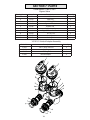
SECTION 7: PARTS
COMPONENT PARTS LIST
REF
NO.
1
DESCRIPTION
Control Valve ,with cover, less bypass,
Metered Initiated (Aqua Pure®)
CWS075ME
MCWS0751M
W12M130-5N3-0N
CWS100ME
MCWS1001M
W12M170-5V3-0N
CWS150ME
MCWS1501M
W12M270-5W3-0N
CWS200ME
MCWS2001M
W12M270-5W3-0N
CWS300ME
MCWS3000M
W12M530-5G3-0N
W12M130-5N3-0E
W12M170-5V3-0E
W12M270-5W3-0E
W12M270-5W3-0E
W12M530-5G3-0E
V3006
FA45TX
-
V3006
FA45TX
-
V3006
FA45TX
-
V3006
FA45TX
-
V3006
5
6
7
8
9
10
11
Control Valve ,with cover, less bypass,
Metered Initiated (MacCLEAN®)
Bypass
Threaded Tank Adapter
Tank Adapter Coupling
(4” x 8 x 2.5” x 8)
O-ring Included with Item #3
Clamp Assy
Media Tank w. Base (Incl. Ref 9)
Cyclone Assy.
Media
Brine Line Tubing
Brine Tank Complete
ORG-234
FC45XX
MTP0744FB
C04N-44
H-075P
13000X
BT1534X
ORG-234
FC45XX
MTP0844FB
C04N-44
H-10P
13000X
BT1534X
ORG-234
FC45XX
MTP1044FB
C04N-44
H-10P & H-075P
13000X
BT1534X
ORG-234
FC45XX
MTP1054FB
C04N-54
H-10P (X2)
13000X
-
MTP1465B
C04N-65
H-10P (X3)
13000X
BTCS33BK
12
13
14
15
Brine Tank Complete w/ Extension Kit
Overflow Fitting
Brine tank Shell w / cover
Brine Well w / Cap
Grid Plate
BT16
BT1534L
BT15BW
BT15GP
BT16
BT1534L
BT15BW
BT15GP
BT16
BT1534L
BT15BW
BT15GP
BT1534X-EXT
BT16
BT1534L
BT15BW
-
BT16
BT1833BK
H1030-28
BTCS12-18
16
17
18
19
Grid Plate wit Extension Kit
Safety Brine Valve, Complete
Safety Brine Valve
Float Assembly
Air Check Assembly
BT15SBVA
60014
60068X
60002-27.5
BT15SBVA
60014
60068X
60002-27.5
BT15SBVA
60014
60068X
60002-27.5
BT15GP-EXT
BT15SBVA
60014
60068X
60002-27.5
10002X-24.0
60014
60068X
60002-24
2
3
4
2752-2
Note: When ordering replacement or repair components always specify by the unit or model number
to ensure correct parts delivered.
Items Not Shown
Description of Item
Part Number
Wrench
V3193-01
Universal Elbow
V3191-01
Retaining Clip
H4615
Drain Line Insert
PKP10TS8-BULK
Drain Line Elbow Nut
V3192
Drain Line Elbow
3158-01
Plumbing Adapter Kits
1” Brass Sweat
V3007-02
1” Plastic Male NPT
V3007-04
1.25” Plastic Male NPT V3007-05
1” Plastic Male BSP
V3007-06
OFF
2
OFF
OFF
3
OFF
1
16
10
6
17
5
18
7
8
19
13
9
14
12
11
15
7-1
SECTION 7: PARTS
COMPONENT PARTS LIST
Drawing No.
1
2
3
4
5
6
*
Not Shown
Front Cover and Drive Assembly
Order No.
Description
V 3175-01 Front Cover Assembly
V 3107-01 M otor
V3106-01 Drive Bracket&Spring Clip
V 3108
PC Board
V 3110
Dri ve Gear 12x36
V 3109
Dri ve Gear Cover
V 3002
Dri ve A SY
V3186
AC Adapter 110V-12
Quantity
1
1
1
1
3
1
*
1
* Drawing number parts 2 through 6 may be purchased as a complete assembly, part V3002.
7-2
6(&7,21 7: 3$576
&20321(17 3$576 /,67
Drive Cap Assembly'RZQÀRZ3LVWRQ
5HJHQHUDQW3LVWRQDQG6SDFHr6WDFN Assembly
Drawing No.
Order No.
Description
Quantity
1
V3005
Spacer Stack Assembly
1
2
V 3004
Dri ve Cap Assembly
1
3
V 3178
Dri ve Back P la te
1
4
V3011
Piston Down Àow Assembly
1
5
V3174
Regenerant Piston
1
6
V 3135
O-ri ng 228
1
7
V 3180
O-ri ng 337
1
8
V3105
O-ring 215 (Distributor Tube)
1
Not Shown
V3001
Body Assembly
1
3
1
2
5
4b
4
8
6
7-3
7
SECTION 7: PARTS
COMPONENT PARTS LIST
Injector Cap, Injector Screen, Injector, Plug and O-Ring
Quantity
Order No.
Description
V 3176
I nj ector Cap
1
V 3152
O-ri ng 135
1
V 3177
I nj ector Screen
1
V3010-1Z Injector ASY Z Plug
1
V3010-1B INJECTOR ASY B BROWN
V3010-1C INJECTOR ASY C VIOLET
5
V3010-1E INJECTOR ASY E WHITE
V3010-1H INJECTOR ASY H GREEN
Not Shown
V 3170
O-ri ng 011
*
Not Shown
V 3171
O-ri ng 013
*
*The injector plug and the injector each contain one 011 (lower) and 013 (upper) o-ring.
Drawing No.
1
2
3
4
7-4
SECTION 7: PARTS
COMPONENT PARTS LIST
Refill Flow Control Assembly
Drawi ng No.
1
2
3
4
5
6
7
Not Shown
Order No.
H4615
JCP-P-6
JCPG-6PBL K
H4613
V 3163
V 3165-01*
V 3182
H4650
Descri pti on
El bow L ocki ng Cl i p
Pol ytube i nsert 3/8”
Nut 3/8”
El bow Cap 3/8”
0-ri ng 019
BLFC Retainer Assembly**
BLFC
Elbow ½” with nut and insert
Quanti ty
1
1
1
1
1
1
1
Option
*Assembly includes V3182 BLFC.
** Includes drawing #7.
4
3
2
5
6
7
1
Water
Flow
Proper BLFC orientation
directs refill water flow
towards the washer face
with rounded edge and
text.
7-5
SECTION 7: PARTS
COMPONENT PARTS LIST
Drain Line – 3/4”
Drawing No.
1
2
3
4
5
6
7
Order No.
H4615
PKP10TS8-BULK
V3192
V3158-01
V 3163
V3159-01
V3162-013
V3162-017
V3162-027
V3162-053
Description
Elbow Locking Clip
Polytube insert 5/8
Nut ¾ Drain Elbow
Drain Elbow ¾ Male
O-ri ng 019
DLFC Retainer Assembly
DLFC 1.3 gpm for ¾
DLFC 1.7 gpm for ¾
DLFC 2.7 gpm for ¾
DLFC 5.3 gpm for ¾
Water
Flow
Proper DLFC orientation
directs water flow towards
the washer face with
rounded edge.
7-6
Quantity
1
1
1
1
1
1
One DLFC
must be
used if ¾
¿WWLQJLVXVHG
SECTION 7: PARTS
COMPONENT PARTS LIST
Water Meter and Meter Plug
Drawing No.
1
2
3
4
5
Order No
Description
V 3151
Nut 1” QC
V 3003
Meter Assembly (includes drawing #3 & #4)
V 3118-01
Turbi ne
V 3105
0-ri ng 215
V 3003-01
Meter Plug Assembly
4
5
3
2
1
7-7
Quantity
1
1
1
1
1
SECTION 7: PARTS
COMPONENT PARTS LIST
Order No:V3007-02
Description: Fitting 1” Brass Sweat Assembly
Order No:V3007-03
Description: Fitting 3/4” Brass Sweat Assembly
Quantity
Drawing No.
1
V3151
Nut 1” Quick Connect
2
1
V3151
Nut 1” Quick Connect
2
V 3150
Split Ring
2
2
V 3150
Split Ring
2
3
V 3105
O-Ri ng 215
2
3
V 3105
O-Ri ng 215
2
4
V3188
2
4
V3
Fitting 3/4” Brass Sweat Assembly
2
Drawing No.
Order No.
Description
Fitting 1” Brass Sweat Assembly
Order No.
4
Description
Quantity
2
4
3
3
1
1
2
2
Order No: V3007-04
Description: Fitting 1” Plastic Male NPT Assembly
Description
Order No:V3007-05
Description: Fitting 1 1/4” Plastic Male NPT Assembly
Drawing No.
Order No.
Quantity
Drawing No.
1
V3151
Nut 1” Quick Connect
2
1
V3151
Nut 1” Quick Connect
2
V3150
Split Ring
2
2
V 3150
Split Ring
2
3
V3105
O-Ring 215
2
3
V 3105
O-Ri ng 215
2
4
V3164
Fitting 1" Plastic Male NPT
2
4
V3317
Order No.
4
Description
Fitting 1 1/4” Plastic Male NPT
4
1
1
2
2
3
3
1 NPT
7-8
Quantity
2
2
SECTION 7: PARTS
COMPONENT PARTS LIST
Bypass Valve
Drawing No.
Description
Order No.
1
V3151
2
V 3150
3
4
Quantity
Nut 1” Quick Connect
2
Split Ring
2
V 3105
O - R i ng 215
2
V 3145
Bypass 1” Rotor
2
5
V 3146
Bypass Cap
2
6
Bypass Handle
2
7
V 3147
V 3148
8
V 3152
O - r i ng 135
2
9
V 3155
O - r i n g 11 2
2
10
V 3156
O - r i ng 214
2
Bypass Rotor Seal Retainer
2
V3191-01 Vertical Adapter Assembly
Description
Order No.
V 3151
Quantity
Nut 1” Quick Connect
Split Ring
2
V 3105
O - R i ng 215
2
V 3191
Vertical Adapter
2
V 3150
2
6
5
6
5
4
4
1
1
1
2
3
1
2
3
7-9
SECTION 7: PARTS
COMPONENT PARTS LIST
Wrench
(Order No. V3193-01)
Although no tools are necessary to assemble or disassemble the valve, the wrench (shown in various positions
on the valve) may be purchased to aid in assembly or disassembly.
7-10
SECTION 8: LIMITED WARRANTY
Please read and complete the following limited warranty and mail the bottom half within 10 days of purchase
CUNO Incorporated warrants to the original purchaser-consumer of its
Product that it is free of defects in materials and workmanship. Any defect,
malfunction, or other failure of this product to conform to this Limited
Warranty will be remedied by CUNO in the manner provided below.
This Limited Warranty, together with any and all warranties implied by
law, shall be limited to a duration described herein, from the date of
purchase by the consumer with the following exclusions and limitations
as follows:
• Three years on entire unit
• Five years on mineral tank only
(does not include internal components)
• Five years on control valve body only
(does not include internal or external components)
• Five years on salt storage container and components.*
This Limited Warranty does not apply to defects that result from abuse,
misuse, alterations or damage not caused by CUNO.
IMPORTANT: To file a claim under this warranty you must complete
and mail the Warranty registration card supplied with this Product to
CUNO at the address below within ten (10) days of original retail
purchase.
CUNO Incorporated, 400 Research Parkway, Meriden CT 06450 U.S.A.
THIS WARRANTY DOES NOT COVER, AND IS INTENDED TO
EXCLUDE, ANY LIABILITY ON THE PART OF CUNO, WHETHER
UNDER THIS WARRANTY OR UNDER ANY WARRANTY IMPLIED BY
LAW, FOR ANY INDIRECT OR CONSEQUENTIAL DAMAGES FOR
BREACH HEREOF OR THEREOF.
such loss or damages are sought, including breach of warranty or
contract, negligence or strict liability.
RESPONSIBILITY OF CUNO
CUNO's responsibility under this warranty shall be to repair at its
expense, and at no charge to the original purchaser-consumer, any
Product that is actually defective, malfunctioning, or otherwise in violation
of this Warranty.
If CUNO, for any reason, cannot repair a Product covered hereby within
two (2) weeks after inspection of the unit by CUNO or its authorized
representative, then CUNO's responsibility shall be, at its option, either to
replace the defective Product with a comparable new unit at no charge to the
consumer or to refund the full purchase price. CUNO's obligations of repair,
replacement, or refund are conditioned upon the consumer's making the
product available for instpection by CUNO or it’s authorized representative.
If any Product covered hereby is actually defective within the terms of
this Warranty, then CUNO will bear all the reasonable and proper
shipping or mailing charges actually incurred in the consumer's return of
the Product set forth herein. If the Product proves not to be defective
within the terms of this Warranty, then all costs and expenses in
connection with the processing of the consumer's claim hereunder shall be
borne by the consumer.
RESPONSIBILITY OF THE CONSUMER
The original purchaser-consumer's sole responsibility in the instance of
a Warranty claim shall be to notify CUNO of the defect, malfunction, or
other manner in which the terms of this Warranty are violated. You may
secure performance or obligations hereunder by (in writing):
1. Identifying the Product involved (by model or serial number or other
sufficient description that will allow CUNO to determine which Product is defective).
Note: Some states prohibit limitations on the duration of implied
warranties and on the exclusion of indirect or consequential damages,
and so the above limitation on implied warranties and on incidental and
consequential damages may not be applicable to you.
CUNO makes no guarantees or warranties, expressed or implied,
including, but not limited to, any implied warranty of merchantability of
fitness for a particular purpose or implied warranty arising out of a course
of dealing, custom, or usage of trade whatsoever with respect to these
instructions.
CUNO shall not under any circumstances be liable to the recipient of
these instructions for any direct, indirect, special, incidental, or
consequential loss or damages (including, but not limited to, loss of
profits, revenue, business, opportunity, or goodwill) resulting from or in
any way related to these instructions or the recipient’s non-adherence to
these instructions, regardless of the legal or equitable theory under which
2. Specifying where, when and from whom the Product was purchased.
3. Describing the nature of the defect, malfunction or other violation of
this Warranty.
4. Sending such notification to:
CUNO Incorporated, 400 Research Parkway, Meriden CT 06450 U.S.A.
5. And, making the product available for inspection by CUNO or it’s
authorized representative.
THIS WARRANTY GIVES YOU SPECIFIC LEGAL RIGHTS, AND YOU
MAY ALSO HAVE OTHER RIGHTS WHICH MAY VARY FROM STATE
TO STATE.
*water softeners only
WATER TREATMENT SYSTEM
WARRANTY/RECORD OF PURCHASE CARD
IMPORTANT NOTICE: THIS CARD MUST BE RETURNED WITHIN
TEN (10) DAYS OF PURCHASE TO REGISTER YOUR WARRANTY
CUNO Incorporated, 400 Research Parkway, Meriden CT 06450 U.S.A.
DATE OF
PURCHASE
PLEASE PRINT
THANK YOU
Mo.
Your Name
Business Name
Address
Street
City
Telephone Number (
State & Zip Code
)
Yr.
E-mail Address
Model #
Where Purchased
City
Business Address
State & Zip Code
Street
Equipment this system is used on
Model # (if known)
Manufacturer
If this system is used in conjunction with other filtration devices, please list below.
Equipment
Model
Manufacturer
U.S. Patents 6379630, 5951855, 5699930 and 5584411
8-1
CUNO, Aqua-Pure and MacCLEAN are trademarks of 3M Company used under license.
© 2006 3M Company. All rights reserved.