1
INSTALLATION
AND OPERATING
INSTRUCTIONS
NBW SERIES RESIDENTIAL
BACKWASH FILTERS
MODELS
NBW1000
NBW1500
NBW2000
NBW2500
NBW1628
NBW1001
NBW1501
NBW2001
NBW2501
NBW1628-1
Manufactured by:
Cuno Water Treatment
12628 U.S. 33 North, Churubusco, IN 46723
Water Treatment Division of
IN123G(03-014)
TABLE OF CONTENTS
SECTION
1
2
3
4
5
DESCRIPTION
BEFORE INSTALLATION
INSTALLATION
MAINTENANCE
TROUBLESHOOTING
SPECIFICATION AND OPERATING DATA
Copyright @ 2003 by Cuno Water Treatment. All rights reserved. Not to be reproduced in any form without written permission.
SECTION 1: BEFORE INSTALLATION
INSPECTING AND HANDLING YOUR FILTER:
ACTIVATED CARBON
Inspect the equipment for shipping damage. If damaged,
notify the transportation company and request a damage
inspection.
Activated carbon is generally used to remove objectionable tastes and odors from water, chlorine being the most
common. Activated carbon works primarily on the concept of adsorption. Each particle of carbon has numerous pores through which the water passes. It is in these
pores that the removal of unwanted constituents occurs.
During backwash, these "collected" contaminants are
knocked off and flushed away to drain. Since the pores in
the carbon are very important, the presence of sedimemt
in the water which can plug these pores will greatly shorten
the run time and life span of the carbon.
Handle the filter with care. Damage can occur if dropped
or set on sharp, uneven projections on the floor. Do not
turn the filter upside down.
MAKE SURE YOUR WATER HAS BEEN THOROUGHLY
TESTED:
An analysis of your water should be made prior to the
selection of your water conditioning equipment. Your
dealer will generally perform this service for you, and may
send a sample to the factory for analysis and recommendations Enter your analysis below for a permanent record.
Activated carbon can be used to remove Radon gas and
organic compounds from water. Check with the local board
of health for the acceptability of using carbon for the removal of these contaminants. The life span of the carbon
depends on the amount of contaminant in the water and
amount of water filtered per day. Rarely will the carbon
last more than three (3) years.
NOTE: Hydrogen sulfide (H2S) must be tested for at the
well site. For accuracy, the sample must be drawn with
the pump RUNNING and the test be completed within
ONE minute after the sample is drawn.
FILTER AG
Filter Ag is used to remove turbidity from water. While it
is good general purpose filtering media, it has its limitations. It will remove particles down to approximately 20
micron in size, but cannot be used to filter out sand. The
material to be removed must have a density less than
that of Filter Ag itself.
ANALYSIS OF YOUR WATER
Hardness
Iron (Fe)
Manganese (Mn)
pH
Tannins (Humic Acid)
Hydrogen Sulfide (H2S)
Other _____________
Other _____________
_________ gpg
_________ ppm
_________ ppm
_________
_________ ppm
_________ ppm
_________
_________
If it is the same or heavier it will not be removed from the
filter during the backwash process and will remain in the
tank. Eventually the filter will plug up causing excessive
pressure drop and requiring the filter tank be emptied and
new filter ag be used.
There are several different filter media which can be used
in this filter. Each is designed to improve a particular
aesthetic problem. None of them should be used to make
non-potable water safe to drink. The following descriptions indicate not only what the media is designed to do,
but also points out their limitations.
Filter Ag will generally last an indefinite period of time, if
the frequency of backwash and the backwash flow rate
are adequate. Replacement is usually necessary when
the filter fails to properly remove the turbidity or pressure
drop becomes excessive.
1-1
NEUTRALIZER
BIRM
Neutralizer media is typically a blend of calcium carbonate (calcite) and magnesium oxide (corosex). This media
is used to elevate the pH of acid water and is generally
used when the pH is approximately 6.0-6.5. The filter
media dissolves when water with a low pH passes through.
The blend is used to take advantage of the fast, vigorous
pH adjusting capabilities of corosex and the slow, longlasting capabilities of the calcite. Neutralizer is typically
not recommended when the pH of the raw water is below
5.5, because the dissolve rate would be high and thus
constant maintenance of the filter would be necessary.
In these cases a chemical feed pump injecting soda ash
is usually recommended.
Birm can be used to remove iron from water, but has limitations which typically do not make it a practical alternative to other iron filters, such as the Chem-Free filter. When
used to remove iron, the pH of the water must be 6.8 or
higher and the dissolved oxygen (D.O.) level must be equal
to 15% of the iron concentration. If used to remove manganese, the pH must be 8.0-9.0. Birm should not be used
to remove hydrogen sulfide and cannot be used if the
water contains organic compounds.
Neutralizer media will require replenishment periodically.
The frequency is dependent on the raw water pH and
your water consumption habits. The lower the pH and
the higher the water usage, the more frequently replenishment will be required. One easy way of determining
when to replenish is by placing a mark on the outside of
the tank at the level of the media when first installed.
Periodically shine a bright light through the tank and compare the current level to the mark, if it is down more than
three (3) inches, add media to the mark. If you are unable to see through the tank, remove the control valve
and measure down to the top of the media. The tank
should be 2/3 full, if not, add media.
CHECK YOUR WATER PRESSURE AND PUMPING
RATE:
Birm will require periodic replacement. Although it is not
sacrificial, it will lose its effectiveness over time.
Two water system conditions must be checked carefully
to avoid unsatisfactory operation or equipment damage:
1)
Minimum water pressure required at the filter tank
inlet is 20 psi. IF PRESSURE IS OVER 100 PSI, A
PRESSURE REDUCING VALVE MUST BE INSTALLED IN THE WATER SUPPLY LINE.
NOTE: If you have a municipal or a community water
supply and daytime water pressure is 85 psi or more,
nighttime pressure may exceed 100 psi. Call your
local water department or plant operator to obtain
pressure readings. If you have a private well, the
gauge on the pressure tank will indicate high and low
system pressure. Record your water pressure data
below:
CAUTION: Since neutralizer media dissolves as it raises
pH, it will increase the hardness. If your home is equipped
with a tankless water heater, a water softener must be
installed after the filter to prevent the coil from plugging.
FILTER SAND
WATER PRESSURE
Filter Sand performs a similar function to filter ag (discussed earlier). It is used to remove turbidity and has the
same limitations as filter ag. Due to its coarse physical
structure, filter sand will "scrub" itself clean and, for this
reason, it may be better for removing oxidized iron and
sulfur from water than filter ag.
Low _________psi
High ________psi
2) The pumping rate of your well pump must be sufficient for satisfactory BACKWASH. Although the density of a media normally determines the backwash
rate, all the media discussed earlier will require the
same flow rate. Model NBW1001 requires a 5 gpm
rate (refer to SPECIFICATIONS AND OPERATING
DATA for the backwash requirement for other models).
To measure the pumping rate of your pump, follow
these instructions:
COROSEX OR CALCITE
Corosex and calcite, like neutralizer which is a blend of
these two items, are used to adjust pH. Corosex can be
used alone, when it is desirable to have a media which is
very vigorous in its adjustment of pH. Calcite can be used
alone, when only a slight pH adjustment is required. Both
media are sacrificial (dissolve) when adjusting pH and will
thus increase hardness as well. Replenishment will be
required
a.
CAUTION: Since both media increase hardness, if your
home contains a tankless water heater, a water softener
must be installed after the filter to prevent the coil from
plugging.
1-2
Make certain no water is being drawn. Open
spigot nearest pressure tank. When pump starts,
close spigot and measure time (in seconds) to
refill pressure tank (when pump shuts off). This
figure represents CYCLE TIME.
b.
With the pressure tank full, draw water into a container of known volume, measure the number of
gallons drawn until the pump starts again. This is
DRAW-DOWN. Divide this figure by CYCLE TIME
and multiply by 60 to arrive at the PUMPING
RATE in gallons per minute (gpm). To aid in your
calculation, insert the data in the following formula:
THE IMPORTANCE OF YOUR PRESSURE TANK:
A properly sized pressure tank will require a minimum
pump cycle of 60 seconds to refill from pump on-to-off
pressure settings.
NOTE: If your pressure tank (or any part of your water
system) is not functioning properly, corrective action
MUST be taken before installation of your filter.
DRAW-DOWN ____ ÷ CYCLE TIME ____ x 60
(gals.)
(secs.)
FACTS TO REMEMBER WHILE PLANNING YOUR INSTALLATION:
= PUMPING RATE _____
(gpm)
1) All installation procedures MUST conform to local and
state plumbing codes.
EXAMPLE: CYCLE TIME is 63 secs.; DRAWDOWN is 8 gals.; then PUMPING RATE equals:
2) All lawn sprinkling, a swimming pool, geothermal heating/cooling or water for other devices/activities are to
be treated by the filter, a larger model filter must be
selected to accomodate the higher flow rate demands
of these items. The pumping rate of the well pump
must be sufficient to accomodate these items plus
the backwashing requirement of the filter. Consult
your dealer for alternative instructions if the pumping
rate is insufficient.
8 gals. ÷ 63 secs.x 60 = 7.6 gpm
LOCATE WATER CONDITIONING EQUIPMENT CORRECTLY:
Select the location of your filter tank with care. Various
conditions which contribute to proper location are as follows:
3) Remember that the filter INLET is attached to the pipe
that supplies water (i.e., runs to the pump) and the
OUTLET is the line that runs toward the water heater.
1) Locate as close as possible to water supply source.
2) Locate as close as possible to a floor or laundry tub
drain.
4) Before commencing the installation it is advisable to
study the existing piping system and to determine the
size, number and type of fittings required.
3) Locate in correct relationship to other water conditioning equipment.
NOTE: If the plumbing system is used as the ground
leg of the electric supply, continuity should be maintained by installing ground straps around any nonconductive plastic piping used in installation.
4) Filters and softeners should be located in the supply
line BEFORE the water heater. Temperatures above
100°F (38°C) damage filters and softeners and will
void the factory warranty.
5) IMPORTANT: Always use thread tape on threaded
plastic fittings. NEVER use pipe dope, as it will deteriorate the plastic fittings.
5) Do NOT install a filter or softener in a location where
freezing temperatures occur. Freezing may cause permanent damage to this type equipment and will also
void the factory warranty.
6) Allow sufficient space around the unit for easy servicing.
1-3
SECTION 2: INSTALLATION
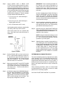
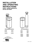
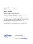
Figure 1. INSTALLATION SEQUENCE
Step 3. Cut main supply line as required to fit plumbing to
INLET and OUTLET of BYPASS VALVE ASSEMBLY.
Step 1. (a) Add media thru fillport adaptor using funnel
(See Figure 2). Fillport cap can be removed by
removing quick release clip. NEVER ADD MEDIA ABOVE LINE INDICATED ON SIDE OF
TANK. You may have received more media than
required for the initial fill, save extra media for
future replenishment.
Step 4. Attach plumbing. DO NOT apply heat to any fitting
connected to BYPASS or CONTROL VALVE, as
damage may result to internal parts or connecting
adapters. MAKE CERTAIN WATER FLOW ENTERS THROUGH INLET AND DISCHARGES
THROUGH OUTLET.
(b) Reinstall fillport cap. Make sure cap is fully
inserted before reinstalling clip.
NOTE: Always use thread tape on threaded plastic fittings. Never use pipe dope, unless specially
formulated for plastic fittings, as it will deteriorate
plastic fittings.
(c) If BYPASS VALVE/YOKE ASSEMBLY is not
factory pre-installed, attach using clips and screws
shown in Figure 3.
Step 2. Shut off all water at main supply. On a private
well system, turn off power to pump and drain
pressure tank. Make certain pressure is relieved
from complete system by opening nearest faucet
to drain system. SHUT OFF FUEL SUPPLY TO
WATER HEATER.
FIigure 3. INLET/OUTLET CONNECTIONS
Figure 2. FILLING MEDIA TANK
2-1
Step 5.
Attach DRAIN LINE to DRAIN LINE
FITTING.To prevent back pressure from reducing the flow rate below minimum required for
backwash, DRAIN LINE MUST be sized according to run length and relative height. Be careful
not to bend flexible drain tubing sharply enough
to cause "kinking" (if kinking occurs DRAIN
LINE MUST be replaced!). Typical examples
of proper DRAIN LINE diameters are:
IMPORTANT: Filters containing activated carbon, filter ag or birm must be saturated for at
least 2 hours prior to subjecting the unit to full
backwash flow rates. Failure to do this may
result in loss of mineral during initial backwash
procedure.
(b) Once a steady stream of water is flowing to
drain (see IMPORTANT note above) open both
INLET and OUTLET KNOBS OF BYPASS
VALVE completely. Leave unit in backwash for
at least 10 minutes OR until drain line water runs
clear, whichever is longer.
1) 1/2 in. ID up to 15 ft. when discharge is
lower than inlet.
2) 5/8 in. ID up to 15 ft. when discharge is
slightly higher than inlet.
Step 9.
3) 3/4 in. ID when drain is 25 ft. away.
Avoid installing drain overhead or using flexible
vinyl tubing, either may result in failure.
After this preliminary backwash, manually advance CONTROL VALVE to "SERVICE" position and plug timer into a 110V, 60Hz properly
grounded non-switched power source.
Step 10. Set time of day (see "HOW TO SET TIME CONTROL") and set BACKWASH frequency (see "DETERMINING BACKWASH FREQUENCY"). Installation is now complete.
Some areas prohibit the use of flexible drain
lines. Check with local code officials prior to
installation.
NOTE: During the initial backwashings, a small
amount of media may be observed in drain water. This is normal and beneficial for efficient
operation of your filter system.
Step 11. Manually initiate a complete "regeneration" process, allowing the unit to automatically proceed
through a backwash and rapid rinse. See "HOW
TO MANUALLY BACKWASH YOUR FILTER
AT ANY TIME", Page 2-3. Check drain water
at end of rapid rinse cycle, if water is cloudy
repeat the BACKWASH process. RESTORE
FUEL SUPPLY OR POWER TO WATER
HEATER.
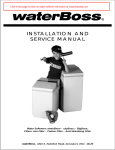
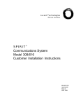
Figure 4. DRAIN
Step 6.
Step 7.
Position DRAIN LINE over drain and secure
firmly. To prevent back-siphoning of sewer water, provide an air gap of at least 2 inches or 2
pipe diameters between end of drain hose and
drain (See FIGURE 4). Do not raise DRAIN
LINE more than 10 ft. above floor.
DETERMINING BACKWASH FREQUENCY:
The exact backwashing frequency depends on the quality
of the raw water, but it is recommended that filters containing activated carbon, birm, filter ag or filter sand be
programmed to backwash at least once every six days. If
pressure drop becomes excessive or contaminant reappears in the treated water before six days, increase the
frequency.
Make certain both INLET and OUTLET KNOBS
of BYPASS VALVE are in "BYPASS" position.
Turn on power to well pump or completely open
main supply valve. Check for leaks and correct as necessary.
Filters containing neutralizer, calcite or corosex should
be backwashed every other day to prevent the media
particles from "cementing" together.
Step 8. (a) Manually stage control to BACKWASH position (see "HOW TO MANUALLY CYCLE PROGRAM"). Open BYPASS VALVE INLET KNOB
approximately 1/4 of the way to full open ("SERVICE" position) allowing unit to fill slowly. This
will purge any entrapped air in the bed.
See "HOW TO SET TIME CONTROL" for procedure.
2-2
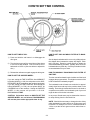
HOW TO SET TIME CONTROL
HOW TO SET DAYS ON WHICH FILTER IS TO BACKWASH:
HOW TO SET TIME OF DAY:
1) Press and hold the red button in to disengage the
drive gear.
Set the days that backwash is to occur by sliding tabs on
the skipper wheel outward to expose trip fingers. Each
tab is one day. Extend or retract fingers to obtain the
desired backwashing schedule. Typically, these units are
backwashed every third day. Consult your dealer for their
recommendations for your water.
2) Turn the large gear until the actual time of day shows
in the time of day window. Unit will now be set to
backwash at 1:00 a.m.(See note below to adjust this
time.)
HOW TO MANUALLY BACKWASH YOUR FILTER AT
ANY TIME:
3) Release the red button to again engage the drive gear.
HOW TO SET THE SKIPPER WHEEL:
Turn the manual backwash knob clockwise until the knob
engages the program wheel. This slight movement of the
knob will start the backwash program.
If you are setting the TIME CONTROL after MIDNIGHT
but before NOON (i.e. A.M.) the red pointer on the SKIPPER WHEEL MUST be between two numbers (as shown)
if you are setting the TIME CONTROL after NOON but
before MIDNIGHT (i.e. P.M.) the red pointer MUST be
COVERING one of the numbers. Setting the SKIPPER
WHEEL in this manner will provide a 1:00 A.M.
BACKWASHING TIME.
The backwash knob will make one revolution in approximately three hours and stop in the position shown in the
drawing. Even though it takes three hours for the knob to
complete one revolution, the backwash cycle of your unit
might be about 20 minutes in duration.
In any event, filtered water may be drawn after rinse water stops flowing from the filter drain line.
CAUTION: If directions above on HOW TO SET THE
SKIPPER WHEEL are not followed, BACKWASHING
will not take place at the appropriate time of day.
NOTE: Should it be necessary to change the time of day
which backwash is to start, the time on 24 hour gear must
be altered. For example, if 2:00 a.m. is desired instead of
1:00 a.m.,set the 24 hour gear one hour earlier than actual time.
2-3
SECTION 3: MAINTENANCE
TO REPLENISH (REBED) MEDIA:
1) At least every six months you should check the time
of day setting. Power outages will cause the unit to
lose time.
1) Pressure must be relieved on system by turning both
INLET and OUTLET KNOBS of BYPASS VALVE to
"BYPASS" position and manually rotating CONTROL
VALVE to "BACKWASH" position.
2) If your unit contains activated carbon, you must replace the carbon and gravel underbed at least every
three (3) years. Replacement may be required sooner,
if the taste and odor being removed reappears in the
treated water or pressure drop, due to fouling of the
media, becomes excessive.
2) Remove fillport cap by removing the clip. Some water will spill out.
3) Using a small tube, syphon water from the tank
through the fillport.
3) Filter Ag and Filter Sand will last an indefinite period
of time. It may be necessary to replace them, if the
pressure drop across the filter becomes too great or
filtration results drop.
4) Add media through the fillport using a funnel. Do not
add media to a level above the line indicated on the
side of the tank.
4) Neutralizer media, calcite or corosex must be replenished at least annually. At the time of installation, it is
advisable to mark the level of the media on the outside of the tank. At a later date you can shine a bright
light through the tank comparing the current level with
the mark. If the level is down by more than three (3)
inches, add media back to the original mark.
5) Reinstall fillport cap. Make sure cap is fully inserted
before reinstalling clip.
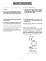
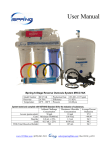
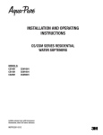
SPECIAL SERVICE INSTRUCTIONS:
Under normal circumstances removal of valve should
never be required. However, if it must be removed, it can
be done by disassembling the quick release clamp, by
removing latch. Pressure should be relieved before attempting any disassembly. Upon reassembly, all o-rings
should be lubricated with silicone grease. Reassemble
clamp as shown in Figure 5. MAKE SURE ARROWS ON
LATCH SIDE OF CLAMP ARE ALIGNED.
5) Birm should be replaced when iron reappears in the
treated water and backwashing does not return the
media to a functional form.
Figure 5. CLAMP ASSEMBLY
3-1
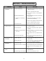
SECTION 4: TROUBLESHOOTING
PROBLEM
1) Excessive pressure drop
through filter
CAUSE
SOLUTION
A) Filter not backwashing.
1) Check motor by manually initiating a regeneration,
replace as necessary.
2) Check for uninterrupted power supply.
3) Check backwash frequency. Change program if
necessary.
B) Filter bed loaded with sand.
1) Verify sediment being removed is less dense than
the filter media.
C) "Cementing" or "Channeling" of
media.
1) Probe bed for this condition. Verify adequate
pumping rate for backwashing.
2) Check for frozen, plugged or restricted drain line.
3) Check for adequate backwash frequency.
2) Contaminant not being
properly removed
D) Top Screen Fouled
1) Remove screen and clean as necessary.
A) Leaking bypass valve.
1) Check bypass valve in "SERVICE" position. Repair
or replace if necessary.
B) Internal valve leak.
1) Check piston and spacers and seals. Replace as
necessary.
C) Distributor not properly seated in
control valve.
1) Make sure distributor is in tube adaptor protruding
from bottom of control valve.
2) Check distributor tube o-ring. Replace as necessary.
3) Filter raises pH too high
(Neutralizer)
4) Filter fails to raise pH
(Neutralizer)
D) Flow rate too high for filter.
1) Check demand requirements against filter recommended flow rates.
A) Filter is brand new.
1) Crack the bypass valve allowing some water to
bypass the unit.
B) Wrong media used.
1) Corosex used when neutralizer blend should have
been used. Crack bypass or rebed unit.
A) Flow rates too high.
1) Verify demand rate does not exceed filter rating.
B) Filter bed cemented or channeled. 1) Verify adequate pumping rate for backwashing unit.
2) Check drain line for freezing, plugging or restrictions.
5) Filter fails to remove iron
(Birm)
A) pH too low.
1) pH of raw water must be 6.8 or higher. Adjust with
proper equipment.
B) Dissolved oxygen level inadequate. 1) Aerator may be installed prior to filter.
4-1
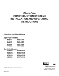
SECTION 5: SPECIFICATIONS AND OPERATING DATA
NBW1001
NBW1501
NBW2001
NBW2501
NBW1628-1
1.0 (0.03)
1.5 (0.05)
2.0 (0.06)
2.5 (0.08)
1.5 (0.05)
18 (8.2)
18 (8.2)
22 (10.0)
25 (11.3)
35 (15.9)
Operating Flow Rate, gpm (lpm) (Note 1):
Continuous (no duration limit)
Service (10 mins. or less)
3 (11)
5 (19)
3 (11)
6 (23)
4 (15)
7 (26)
5 (19)
8 (30)
6 (23)
10 (38)
Backwash Flow Rate, gpm (lpm) (Note 2)
5 (19)
5 (19)
7 (26)
7 (26)
10 (38)
1 (2.54)
1 (2.54)
1 (2.54)
1 (2.54)
1 (2.54)
10 x 44
(25 x 112)
10 x 54
(25 x 137)
12 x 54
(31 x 137)
13 x 54
(33 x 137)
16 x 28
(41 x 71)
12 (31)
18 (46)
56 (142)
12 (31)
18 (46)
66 (168)
12 (31)
18 (46)
66 (168)
13 (33)
18 (46)
66 (168)
16 (41)
18 (46)
40 (102)
45 (20)
51 (23)
57 (26)
68 (31)
66 (30)
ITEM
Filter Media Volume, cu.ft. (cu.mtr.)
Gravel Underbed, lbs. (kg.)
Service Pipe Size, in. (cm.)
Tank Diameter x Height, in. (cm.)
Minimum Space Required, in. (cm.):
Width
Depth
Height
Approximate Shipping Weight, lbs. (kg.)
l/media
Maximum operating temperature 100°F (38°C); Electrical requirements 110V,60Hz (220V, 50 Hz); Operating pressure
20-100 psi (138-689 kPa). Specifications subject to change without notice.
NOTES:
(1) For satisfactory performance, indicated durations should
not be exceeded. Flow rates specified are adequate for normal residential applications. Do not use Service Flow Rates
when sizing commercial applications or if treated water is to
supply a geothermal heat pump, swimming pool, etc.
(2) For system to operate properly, pumping rate of well pump
MUST be sufficient to backwash unit at rate specified.
5-1
COMPONENT PARTS LIST
Ref.
No.
1
2
3
4
5
6
7
8
9
10
11
12
13
14
15
---
Description
Control Valve w/Cover, l/Bypass
Adapter Assy., Flange-Thrd
(Incl.Ref. 3)
O-ring
Clamp Assy. (Incl. Ref. 5)
Latch, Clamp
Fillport Cap Assy. (Incl. Ref. 7 & 8)
O-ring
Quick Release Clip
Fillport Adapter Assy., Blank Cap,
(Incl. Ref. 3, 6, 7 & 8)
Top Screen
Media Tank w/Base
Media (Various Types)
Distributor
Tank Base
Gravel Underbed
Adapter Assy., Thrd-Flange
(Not Shown)
O-ring, Adapter Assy. (Not Shown)
NBW1001
NBW1501
NBW2001
NBW2501
NBW1628-1
N200500
FA45CX
N200500
FA45CX
N200700
FA45CX
N200700
FA45CX
N200000
FA45CX
ORG-234
FC45XX
FC45C
FF45CX
ORG-214
QRC20
FF45BX
ORG-234
FC45XX
FC45C
FF45CX
ORG-214
QRC20
FF45BX
ORG-234
FC45XX
FC45C
FF45CX
ORG-214
QRC20
FF45BX
ORG-234
FC45XX
FC45C
FF45CX
ORG-214
QRC20
FF45BX
ORG-234
FC45XX
FC45C
FF45CX
ORG-214
QRC20
FF45BX
18280
MTP1044FB
(1.0 CF)
C37S-16-45
T06-10P
QC-18
--
18280
MTP1054FB
(1.5 CF)
C37S-16-55
T06-10P
QC-18
--
18280
MTP1254FB
(2.0 CF)
C37S-16-55
T06-12P
QC-22
--
18280
MTP1354B
(2.5 CF)
T37S-16-55
T06A-13P
QC-25
FA45RX
18280
MTP1628FB
(1.5 CF)
C37S-16-29
T06A-16PF
QC-35
--
--
--
--
10381
--
NOTE: When ordering components, always specify model number.
5-2
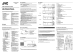
"N'" SERIES
BACKWASH
CONTROL
5-3
"N" SERIES BACKWASH CONTROL PARTS LIST
ONLY THOSE PARTS CIRCLED IN DRAWING AND/OR LISTED BELOW ARE STOCK ITEMS.
ALL OTHERS ARE SPECIAL ORDER, NON-RETURNABLE.
REF.
PART NO.
DESCRIPTION
A
60351-BW
60351-BW-220/50
19231X
19235X
14554X
60102-52
60125
60384X
10090X
60049/18706X
60049/18706-10X
60049/18706-02X
Powerhead Assy., Complete, L/Cover, 110V/60Hz (Incl. Ref. Items 1-27)
Powerhead Assy., Complete, L/Cover, 220V/50Hz (Incl. Ref. Items 1-27)
Skipper Wheel Assy. (incl. Ref. Items 4-9)
12-Hour Gear Assy. (Incl. Ref. Items 10-15)
Control Valve Body Assy. (Incl. Ref. Items 30-36 E & G)
Piston Assembly
Seal Kit (incl. Ref. items 32& 33)
Drain Line Flow Control Assy. (Incl. Ref. Items 37-44)
Adapter Coupling Assy. (Incl. Ref. Items 45-48)
1" NPT Bypass Valve Assy. (Incl. Ref. Items 49-58)
1" BSP Bypass Valve Assy. (Incl. Ref. Items 49-58)
3/4" NPT Bypass Valve Assy. (Incl. Ref. Items 49-58)
22601X
19170
18825
11384
19171
13547
11842
12972
12281
13304
13303
13301
13163
13166
13315
Valve Cover, Specify Model No.
Motor, 110V/60 Hz
Motor, 220V/50Hz
Motor Mtg. & Ground Screw
Main Drive Gear
Strain Relief - Flat Cord
Power Cord, 110V,60Hz, US Plug
Power Cord, 220V,50Hz, European Plug
Tank O-Ring
Distributor Tube O-Ring 1"
Injector Cover O-Ring
Injector O-Ring
Injector/Drain Housing
Injector Cover
Injector Mtg. Screw
Drain Line Flow Control Button:
5.0 GPM
7.0 GPM
Drain Line Flow Control Button Retainer
Drain Line Fitting
Coupling O-Ring
Adapter Coupling
Adapter Clip
Screw - Adapter Coupling
Adapter Yoke, 1" NPT
Adapter Yoke, 1" BSP
Adapter Yoke, 3/4" NPT
B
C
D
E
F
G
H
J
1
26
27
29
30
31
37
38
39
40
41
42
43
44
45
46
47
48
49
50
55
12092
12408
13173
12338
13305
13709
13255
13314
18706
18706-10
18706-02
5-4
FIVE YEAR LIMITED WARRANTY
GENERAL CONDITIONS
WARRANTY POLICY
Damage to any part of this water conditioner because
of misuse, misapplication, neglect, alteration, accident, installation or operation contrary to our printed
instructions, or damage caused by freezing, flood, fire,
vacuum or Act of God, is not covered by this warranty.
In all such cases, regular parts and service charges will
apply.
Cuno Water Treatment, Churubusco, Indiana warrants this water conditioner as stated herein:
We assume no warranty liability in connection with this
water conditioner other than specified herein. This
warranty is in lieu of all other warranties, expressed or
implied, including warranties of fitness for a particular
purpose. We do not authorize any person or representative to assume for us any other obligations on the
sale of this water conditioner.
Should a defect or malfunction occur, contact your
dealer. If you are unable to contact your dealer, return
the part, freight prepaid, directly to the factory (address
below). Enclose with the part a full description of the
problem, with your name, full address, date purchased,
model and serial number and selling dealer's name
and address. We will repair or replace the part and
return it to you at no cost if our repair department
determines it to be defective under the terms of this
warranty.
The serial number is located on the back of the control
valve. Failure to provide the serial number will void the
warranty and may result in charges for parts at the
current selling price.
From the date of installation, we will repair or replace
any part, within the warranty period described below,
which we find defective because of faulty materials or
workmanship or corrosion. You pay only freight to our
factory and local labor charges.
ONE YEAR ON ENTIRE UNIT
FIVE YEARS ON MINERAL TANK EXCLUDING
MINERAL
THREE YEARS ON COMPLETE CONTROL
VALVE
FIVE YEARS ON CONTROL VALVE EXCLUDING INTERNAL AND ELECTRICAL PARTS
FILL IN THE FOLLOWING AND KEEP FOR
YOUR RECORDS.
Date Purchased
Model No.Serial No.
Name of Original Purchaser
This water conditioner is manufactured by:
Cuno Water Treatment
Address of Original Installation
City
12628 U.S. 33 North, Churubusco, IN 46723
Dealer Purchased From
Dealer Address
State