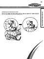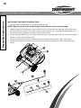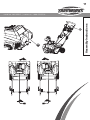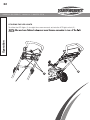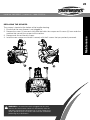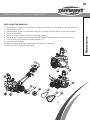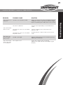
1
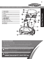
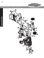
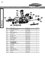
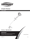
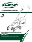
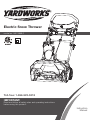
Electric Snow Thrower
model no. 060-3999-2
Toll-free: 1-866-523-5218
IMPORTANT:
IMPORTANT:
Readand
andfollow
follow all
and
operating instructions
Read
allsafety
safetyrules
rules
and
before using
this product.
operating
instructions
before using
this product.
Instruction
Manual
2
Table of Contents
model no. 060-3999-2 | contact us: 1-866-523-5218
SPECIFICATIONS
KNOW YOUR THROWER
EXPLODED VIEW
PARTS LIST
SAFETY GUIDELINES
ELECTRICAL
ASSEMBLY INSTRUCTIONS
OPERATION
MAINTENANCE
TROUBLESHOOTING
SYMBOLS
WARRANTY
Motor:
Blade speed:
Clearing width:
Clearing depth:
Discharge distance:
Impeller size:
Wheels:
Weight:
2
3
4
5
8
12
14
18
23
27
28
29
120 V, 60 Hz, 13 A
Up to 2,600 RPM
20” (50.8 cm)
10” (25.4 cm)
Up to 20’ (6 m)
16” (40.6 cm)
7” (17.7 cm)
33 lb (15 kg)
3
model no. 060-3999-2 | contact us: 1-866-523-5218
14
15
13
12
1
10
9
11
8
5
7
6
KNOW YOUR THROWER
• Carefully remove the product and any accessories from the box. Make sure that all items
listed in the packing list are included.
• Inspect the product carefully to make sure no breakage or damage occurred during shipping.
• Do not discard the packing material until you have carefully inspected and satisfactorily
operated the product.
• If any parts are damaged or missing, please call 1-866-523-5218 for assistance.
!
WARNING: If any parts are damaged or missing, do not operate this product
until the parts are replaced. Using a product with damaged or missing parts
could result in serious personal injury.
!
WARNING: Do not attempt to modify this product or create accessories
not recommended for use with this product. Any such alteration or
to possible serious personal injury.
16
2
3
4
Know Your Thrower
1. Upper handle
2. Middle handle
3. Lower handle
4. Wheel
5. Carrying or lifting handle (for transport only)
6. Scraper
7. Impeller
8. Discharge chute
9.
10. Cord retainer
11. Chute control rod
12. Safety switch button
13. ON/OFF switch bar lever
14. Handle bar
15. LED lights
16. Cam locks
4
Exploded View
model no. 060-3999-2 | contact us: 1-866-523-5218
5
Item
Description
Drawing
QTY
1
2
3
4
5
6
7
8
9
10
11
12
13
14
15
16
17
18
19
20
21
22
23
24
25
26
27
28
29
30
31
32
33
34
Left side cover
Screw
Belt
Screw (M5×15)
Washer
Front cover assembly
Rear cover
Motor
Motor clamp
Wire clamp
Split pin
7” wheel assembly
Rubber sleeve
Wheel bracket assembly
Screw
Lower handle
Nut M6
Knob
Right side cover
Bolt (M6x35)
U bolt
Middle handle
Cord retainer
Screw
Bracket for the chute control rod
Nut
Lower chute control rod
Handle bar assembly
Handle for the chute control rod
Rubber bushing for the chute control rod
Upper chute control rod
Washer
Hitch pin
Cam lock assembly
332041205-2
32205877
329151205
32203100
3290250
311011210
341021205-2
361011210
332101210
3410801
3290135
311031206
332151205
332021205
32201699
333031205-2
32222301A
3410835-4
332051205-2
32204234
333041205
333021205-2
34120227
32215301A
341131205-4
32219121
333111205-2
311041210
311051210
342011205
333201205
3220898
3320643
31102467
1
20
1
4
4
1
1
1
1
1
2
2
2
1
4
1
4
4
1
4
4
1
1
1
1
1
1
1
1
1
1
2
1
2
Parts List
model no. 060-3999-2 | contact us: 1-866-523-5218
6
Parts List
model no. 060-3999-2 | contact us: 1-866-523-5218
Item
Description
Drawing
QTY
6
6-1
6-2
6-3
6-4
6-5
6-6
6-7
6-8
6-9
6-10
6-11
6-12
6-13
6-14
6-15
6-16
6-17
6-18
6-19
6-20
6-21
Front cover assembly
Link block
Impeller
Right driving block
Drive wheel
Washer
Left side plate
Bushing
Left driving block
Motor support
Front cover
Discharge chute
311011210
332061205
341171205
339011205
34109100-12
32217100
311111205
332111205
339021205
332011206
341011205
341031205
31121210
341061205
341071205
341091205
341081205
322021205
311131205
332121205
341111205
3220898
1
1
1
1
1
1
1
2
1
1
1
1
1
1
1
1
1
1
1
1
1
3
Discharge chute seat
Small gear
Gear seat
Big gear
Nut M12
Right side plate
Axle for the impeller
Scraper
Washer
7
Parts List
model no. 060-3999-2 | contact us: 1-866-523-5218
Item
Description
Drawing
QTY
28
28-1
28-2
28-3
28-4
28-5
28-6
28-7
28-8
28-9
28-10
28-11
28-12
28-13
28-14
28-15
28-16
28-17
Handle bar assembly
Safety switch button
Spring
Faceplate
Switch pressure head
Screw
311041210
34136486-2
33401229A
341141205-2
341201205
3220735N
333011108
341051108
341061108-3
311071210
311081205
3410801
311091205
362011201
363051205
341151205-2
311101206
32205877
1
1
1
1
1
1
2
2
2
1
1
2
1
1
1
1
1
12
Lamp screen
Light head housing
Upper handle assembly
Slider block assembly
Wire clamp
Start cable
Circuit board
Switch
Lower cover
Cord plug assembly
Screw
8
model no. 060-3999-2 | contact us: 1-866-523-5218
GENERAL SAFETY RULES
READ ALL INSTRUCTIONS CAREFULLY
Safety Guidelines
1. Read the instructions carefully. Become familiar with the controls and the proper use of the snow
thrower.
2.
medication.
3. Do not allow children under the age of 14 to operate this snow thrower. Children who are 14 years
of age and older must read the operating instructions and the safety rules in this manual carefully
and understand them thoroughly, and must be trained and supervised by a parent.
4. Inspect the snow thrower before use. Replace any damaged parts. Verify that all fasteners are in
place and secure. Replace any parts that are cracked, chipped, or damaged in any way.
5. Exercise caution in order to avoid slipping or falling.
6. Thoroughly inspect the area where the snow thrower will be used. Remove doormats, sleds,
boards, wires, debris, and other foreign objects that may be thrown by the snow thrower.
7. Verify that the impeller will be able to spin freely before turning the snow thrower on.
8. Dress properly. Wear adequate winter outerwear. Wear long heavy pants, boots, gloves, and long
sleeves. Do not wear loose clothing, jewellery, short pants, or sandals. Do not operate this snow
thrower when barefoot. Secure hair above shoulder level.
9. When operating the snow thrower, wear footwear that does not leak and that will improve footing
on slippery surfaces. Wear rubber-soled boots.
10. Do not attempt to make adjustments while the motor is running.
11. Allow the motor and the snow thrower to adjust to outdoor temperatures before beginning to clear
snow.
12. Wear safety glasses/shields or goggles at all times while operating or performing adjustments
or repairs in order to protect the eyes from foreign objects that may be thrown by the snow
thrower.
!
WARNING: Follow the safety rules closely when using the snow thrower.
In order to ensure the safety of the operator and any bystanders, read
these instructions carefully before using the snow thrower. Keep these
instructions in a safe place for future reference.
9
model no. 060-3999-2 | contact us: 1-866-523-5218
1. Walk. Do not run.
2. Verify that the snow thrower is not in contact with anything before turning it on.
3. Stay away from the discharge chute and impeller openings at all times. Keep face, hands, and
feet away from concealed, moving, or rotating parts.
4. Be attentive when using the snow thrower, and stay alert for holes in the terrain and other hidden
5. Do not use the snow thrower on a gravel or crushed rock surface. Use extreme caution when
crossing gravel/crushed rock drives, walks, or roads.
6. Move up and down slopes when clearing snow. Do not go across a slope. Use caution when
changing direction. Do not use this snow thrower to clear snow from steep slopes.
7. Do not attempt to use the snow thrower on a roof or on any steeply inclined slippery surface.
8. Do not operate the snow thrower if the guards, plates, and other safety protective devices are not
in place.
9. Do not operate the snow thrower near glass enclosures, automobiles, trucks, window wells,
drop-offs, etc. without properly adjusting the angle of the snow discharge. Keep children and pets
away from the work area.
10. Do not force or overload the snow thrower. The snow thrower will perform better and more safely
when it is used at the rate that it was designed to work at.
11. Do not operate the snow thrower at high speeds on slippery surfaces. Look behind when backing
up and exercise caution.
12. Do not direct the discharge toward anyone. Do not allow anyone to move in front of the snow
thrower while it is in use.
13. Wear safety glasses or goggles that meet ANSI Z87.1 standards, and wear ear/hearing protection
when using this snow thrower.
14.
15. To avoid accidental start-ups, remain in the starting position when turning the snow thrower on.
16. The operator and the snow thrower must be in a stable position during start-up.
17. Use this snow thrower only for the purposes it was designed.
Safety Guidelines
FOLLOW THESE RULES WHILE OPERATING THE SNOW THROWER
10
Safety Guidelines
model no. 060-3999-2 | contact us: 1-866-523-5218
18. Do not overreach. Always keep proper footing and balance.
19.
20. If the impeller does not rotate freely due to frozen ice, thaw the snow thrower thoroughly before
attempting to use it.
21. Keep the impeller clear of debris.
22. Do not attempt to clear the impeller while the motor is running or while the snow thrower is
plugged in. Turn the motor off and unplug the snow thrower from the extension cord or the outlet.
23. Keep clothing and body parts away from the impeller.
24. Stop the motor when stopped or when moving from one location to another.
25. Unplug the snow thrower when it is being transported and when it is not in use.
26. After striking a foreign object, turn the snow thrower off and unplug it, and then inspect it for
damage. Repair any damage before restarting and using the snow thrower.
27. If the snow thrower starts to vibrate abnormally, stop the snow thrower immediately and attempt to
determine the cause. Vibration is generally an indication of danger.
28. Stop the motor and unplug the snow thrower whenever the operator is not in the operating
position, before unclogging the impeller, and before making any repairs, adjustments, or
inspections.
29.
30. Allow the snow thrower to run for a few minutes after clearing snow in order to prevent moving
parts from freezing.
31. Only use identical replacement parts and accessories for this snow thrower. The use of
nonidentical parts or accessories could lead to serious injury to the user or damage the snow
thrower, and will void the warranty.
32. Do not pick up the snow thrower while it is plugged in and running. The snow thrower is designed
to travel along the ground.
33. Dress Properly – Do not wear loose clothing or jewelry. They can be caught in moving parts.
34. Wear rubber boots when operating the snow thrower.
35. Operation of the snow thrower in the hand-held position is unsafe, except in accordance
with the special instructions for such use provided in the operator’s manual.
36. Store Idle Snow Throwers Indoors – When not in use, snow throwers should be
stored indoors in dry, locked-up place – out of reach of children.
11
model no. 060-3999-2 | contact us: 1-866-523-5218
1. Verify that the snow thrower is secure while transporting.
2. Store the snow thrower in a dry that will prevent unauthorized use or damage. Keep out of the
reach of children.
3. Keep handles dry, clean, and free of debris. Clean the snow thrower after each use. Refer to
Maintenance Section in this manual for more information.
4. If the labels on the snow thrower become defaced or start to lift off, contact the toll-free helpline,
at 1-866-523-5218.
5. Keep these instructions in a safe place for future reference. Refer to them often, and use them to
instruct other users. Anyone who uses this snow thrower must read these instructions carefully.
6. Maintain the snow thrower with care. Follow the instructions for lubricating and changing
accessories.
Safety Guidelines
OTHER SAFETY WARNINGS
12
model no. 060-3999-2 | contact us: 1-866-523-5218
DOUBLE INSULATION
Double insulation is a concept in safety in electric power tools, which eliminates the need for
the usual three wire grounded power cord. All exposed metal parts are isolated from the internal
metal motor components with protecting insulation. Double insulated tools do not need to be
grounded.
ELECTRICAL CONNECTION
Electrical
This product has a precision-built electric motor. It should be connected to a power supply that
is 120 volts, 60 Hz, AC only (normal household current). Do not operate this product on direct
current (DC). A substantial voltage drop will cause a loss of power and the motor will overheat. If
the product does not operate when plugged into an outlet, double-check the power supply.
EXTENSION CORDS
When using a power tool at a considerable distance from a power source, be sure to use an
extension cord that has the capacity to handle the current the product will draw. An undersized
cord will cause a drop in line voltage, resulting in overheating and loss of power. Use the chart to
determine the minimum wire size required in an extension cord. Only round jacketed cords listed
by Underwriter’s Laboratories (UL) should be used.
When working outdoors with a product, use an extension cord that is designed for outside use.
This type of cord is designated with “WA” on the cord’s jacket.
Before using any extension cord, inspect it for loose or exposed wires and cut or worn insulation.
It is possible to tie the extension cord and power cord in a knot to prevent them from becoming
power cord into the receptacle end of the extension cord. This method can also be used to tie
two extension cords together.
!
WARNING: The double insulated system is intended to protect the user from
shock resulting from a break in the tool’s internal insulation. Observe all normal
safety precautions to avoid electrical shock.
!
WARNING: Servicing of a product with double insulation requires
extreme care and knowledge of the system and hould be performed
the product to your nearest authorized service center for repair. Always
use identical factory replacement parts when servicing.
13
1. Inspect the extension cord and the power cord on a regular basis. Look for deterioration, cuts, or
cracks in the insulation. Inspect the connections for damage. Repair or replace the extension cord
or the power cord if any damage is found.
2. Verify that the impeller and all moving parts have come to a complete stop, and disconnect the
snow thrower from the power supply in order to prevent accidental start-ups before cleaning or
performing any inspections or repairs.
3. Do not abuse the extension cord. Do not carry the snow thrower by the power cord or pull on the
cord in order to disconnect it from the receptacle.
4. Keep the extension cord away from heat, oil, and sharp edges in order to prevent damage.
5. If the extension cord is damaged in any manner while it is plugged in, disconnect it from the outlet
immediately.
6. Prevent any possible disconnection of the power cord from the extension cord while the snow
thrower is in use by using the cord retainer. Refer to the section entitled Using the Cord Retainer.
7. Unplug the snow thrower and allow it to cool down before putting it into storage. Store the snow
thrower indoors.
8. Unplug the snow thrower when it is not in use and before performing any maintenance or repairs.
!
WARNING: Keep the extension cord clear of the working area.
Position the cord so that it will not get caught on lumber, tools, or
other obstructions while you are working with a power tool. Failure
to do so can result in serious personal injury.
Electrical
model no. 060-3999-2 | contact us: 1-866-523-5218
14
model no. 060-3999-2 | contact us: 1-866-523-5218
Assembly Instructions
ASSEMBLING THE HANDLE
1. Align the holes (4) on the middle handle (2) and the lower handle (3). Insert the bolts (5), and use
the handle knobs (6) to tighten them.
2. Align the hole (7) on the middle handle (2) and the upper handle (1). Insert the cam locks (8) and
tighten them with the handle knobs (9) provided. Once tightened, close the cam locks to secure
them in place.
9
8
1
7
2
3
6
5
4
!
NOTE: If the upper handle is loose or separated from the middle
handle, tighten the cam lock handle knobs by turning them clockwise.
Do not overtighten the handle knobs.
15
ASSEMBLING THE DISCHARGE CHUTE
the posts (4) on either side click into the keyed holes (5).
1
3
5
2
4
3
5
2
4
Assembly Instructions
model no. 060-3999-2 | contact us: 1-866-523-5218
16
Assembly Instructions
model no. 060-3999-2 | contact us: 1-866-523-5218
INSTALLING THE CHUTE CONTROL ROD
1. Position the discharge chute (1) so that it faces forward.
NOTE: Align the arrow (2) on the discharge chute with the arrow on the housing.
2. Align the holes (3) on the upper chute control rod (4) with the holes on the lower chute control rod
(5). Insert the hitch pin (6). Insert the end of the chute control rod (7) through the keyed hole (8) in
the bracket that is attached to the top of the middle handle.
3. Ensure that the handle (9) of the chute control rod points upward, and insert the rod into the keyed
hole (10) in the back of the housing.
4. Firmly push the rod into the keyed hole in the back of the housing until it snaps into place.
5. Rotate the handle on the chute control rod to ensure that it moves in the same direction as the
chute.
1
2
7
8
5
3
4
6
17
9
10
Assembly Instructions
model no. 060-3999-2 | contact us: 1-866-523-5218
18
model no. 060-3999-2 | contact us: 1-866-523-5218
POWERING ON AND OFF
1. T
2. While pressing the safety switch button with one hand, use your other hand to simultaneouly pull
the ON/OFF switch bar lever (2) toward you. Once the machine powers on, release the safety
switch button and proceed with operation. The snow thrower can only be started by pressing the
Operation
will not start the machine.
3. To power off, release your grip on the ON/OFF switch bar lever.
1
2
!
CAUTION: Do no attempt to override the operation of this safety
switch.
!
WARNING: Avoid accidental start-ups. Verify that the operator is in
the starting position when using the snow thrower. In order to avoid
serious injury, the operator and unit must be in a stable position when
starting the snow thrower.
19
model no. 060-3999-2 | contact us: 1-866-523-5218
USING THE CORD RETAINER
To use the cord retainer:
1. Fold the extension cord to form a tight loop near the retainer.
2. Push the loop through the bottom hole in the retainer.
3. Slide the loop over the retaining clip, and pull until the cord is secured.
1
Operation
This snow thrower is equipped with a cord retainer (1) in order to prevent the extension cord from
disconnecting from the power cord while the snow thrower is in use. The cord retainer hangs from the
cord guide bar.
NOTE: Do not plug the extension cord into the outlet until it has been connected to the cord
retainer and plugged into the snow thrower.
20
model no. 060-3999-2 | contact us: 1-866-523-5218
ADJUSTING THE DISCHARGE CHUTE AND CHUTE DEFLECTOR
Operation
1. To adjust the discharge chute, rotate the handle (1) on the chute control rod in the direction that
you wish to direct the snow stream.
2. T
2
1
21
model no. 060-3999-2 | contact us: 1-866-523-5218
OPERATING TIPS
4. Begin removing snow near the electrical outlet, and work outward. Work back and forth, and not
away from or towards the outlet.
5. When turning at the end of a swath, step over the cord, and then turn the snow thrower.
6. Overlap each swath, and discharge the snow in the same direction of the wind whenever possible.
7. Shave down large banks of snow by placing the snow thrower on the bank. Allow the weight of
the snow thrower to shave down the bank in a back-and-forth motion.
8. Keep the extension cord clear of obstructions, sharp objects, and all moving parts. Do not pull
sharply on the cord or abuse it in any manner. Inspect the extension cord on a regular basis for
damage that may result in an electric shock. If the extension cord becomes damaged in any way,
replace it immediately.
9. Some controls and moving parts may freeze in certain cold and snowy weather conditions. If
any of the controls become hard to operate, stop the motor, disconnect the extension cord, and
inspect the snow thrower for frozen parts.
10. Do not use excessive force when trying to operate frozen controls. Free all of the controls and
moving parts before using the snow thrower.
11. After clearing the snow, allow the motor to run for a few minutes so that the ice doesn’t freeze any
moving parts. Then shut off the motor, wait for all moving parts to come to a complete stop, and
wipe the ice and snow off the snow thrower. Rotate the discharge chute several times in order
to remove the snow from the discharge chute.
12. Disconnect the extension cord when storing the snow thrower.
!
WARNING: If the snow thrower hits a foreign object while it is in
use, the object could be thrown in the direction of the operator or a
bystander. Thrown objects could cause serious personal injury. Keep
the area to be cleared free of all foreign objects that may be picked
up and thrown by the impeller.
Operation
1. Keep children and pets away from the operating area.
2. Keep the area to be cleared free of stones, toys, or other foreign objects that the impeller can
throw. Such items may be covered by a snowfall and go unnoticed. If the snow thrower strikes
an obstruction or a foreign object during operation, stop the snow thrower, unplug the extension
cord, remove the obstruction, and inspect the snow thrower for damage.
3.
22
model no. 060-3999-2 | contact us: 1-866-523-5218
UTILIZING THE LED LIGHTS
To utilize the LED lights (1) for night time snow removal, activate the LED light switch (2) .
Operation
switch.
1
2
23
model no. 060-3999-2 | contact us: 1-866-523-5218
The scraper is located at the bottom of the impeller housing.
1. Ensure that the snow thrower is not plugged in.
2. Remove the screw (1) from each side plate that holds the scraper and 3 screws (2) from under the
machine that secures the scraper to the machine.
3. Remove and discard the old scraper.
4. Install the new scraper, and fasten it securely with the 5 screws that you previously removed.
1
1
2
!
WARNING: If the extension cord is plugged into the snow
thrower, the snow thrower could start accidentally while the
operator is performing maintenance on it, which could cause
serious personal injury. Disconnect the extension cord before
performing any maintenance.
Maintenance
REPLACING THE SCRAPER
24
model no. 060-3999-2 | contact us: 1-866-523-5218
Maintenance
REPLACING THE DRIVE BELT
1. Ensure that the snow thrower is not plugged in.
2. Remove the 5 screws (1) that secure the left side plate (2) to the frame of the snow thrower.
Remove the side cover.
3. Remove the old belt (3) from the small pulley (5) and large pulley (4).
4. Loop one end of the new belt over the small pulley.
5. Rotate the impeller with the left hand while positioning the belt on the large pulley with the right
hand.
6. Install the left side cover, and secure it using the 5 screws that you previously removed.
5
1
2
3
4
25
model no. 060-3999-2 | contact us: 1-866-523-5218
1. Remove the 5 screws (1) that secure the right side cover (2) to the frame of the snow thrower.
2. Remove the nut (3).
3. Remove the 5 screws (4) that secure the left side cover (5) to the frame of the snow thrower.
4. Remove the belt (6).
5. Using a socket wrench, remove the the large pulley (7).
6. Remove the 5 screws (8) that secure the left side plate (9) and remove the left side plate.
7. Pull the axle (10) and remove the old impeller (11).
8. Install the new impeller.
9. Reinstall the left side plate, large pulley, belt and left side cover.
10. Reinstall the nut and right side cover.
1
2
3
9
11 10
8
7
6
5
4
Maintenance
REPLACING THE IMPELLER
26
model no. 060-3999-2 | contact us: 1-866-523-5218
Maintenance
STORAGE
1. Run the snow thrower for a few minutes in order to melt any snow that may be left on the snow
thrower.
2. Wipe the snow thrower off with a dry cloth before storage. This will help prevent ice building up on
the unit and parts freezing.
3. Disconnect the extension cord from the snow thrower.
4. Inspect the extension cord thoroughly for signs of wear or damage. Replace it if it is worn or
damaged.
5. Inspect the snow thrower thoroughly for worn, loose, or damaged parts. If any parts must be
repaired or replaced, contact the toll-tree helpline, at 1-866-523-5218.
6. Store the extension cord with the snow thrower.
7. Store the snow thrower in a clean, dry place. Cover it in order to provide added protection.
27
PROBLEM
Then handle is not
in position.
The snow thrower
does not start.
The motor is on,
but the impeller
does not turn.
The snow thrower
leaves a thin layer
of snow behind.
POSSIBLE CAUSE
SOLUTION
The bolts are not properly seated.
Make sure the bolts are correctly installed through the
handle bars. Check to see if the hand knobs are tight.
Refer to Assembling the Handle section in this manual.
The switch is defective.
Have the switch replaced by an authorized service
center.
The extension cord is not connected to
the plug.
Connect the plug on the snow thrower to the
extension cord.
The extension cord is not connected to
the power source.
Plug the extension cord into a live 120 V AC, 60 Hz
outlet.
The belt is damaged.
Replace the belt (see the section entitled Inspecting/
Replacing the Drive Belt).
The scraper is worn.
Inspect the scraper for wear or damage.
Replace the scraper (see the section Replacing the
Scraper).
Troubleshooting
model no. 060-3999-2 | contact us: 1-866-523-5218
28
model no. 060-3999-2 | contact us: 1-866-523-5218
Some of the following symbols may be used on this product. Please study them and learn their
meaning. Proper interpretation of these symbols will allow you to operate the product better and
more safely.
Symbols
Symbol
Designation/Explanation
V
Voltage
A
Current
Hz
Frequency (cycles per second)
min
Time
AC
Alternating current
RPM
Revolutions per minute
cm
Centimeter
Kg
Kilogram
Double-insulated construction
/min
Revolutions, strokes, surface speed, orbits etc., per minute
Indicates a potential personal injury hazard
To reduce the risk of injury, user must read and understand operator’s manual
before using this product
Always wear proper eye and hearing protection
STOP
STOP
Stop the machine before leaving the machine
Thrown objects can ricochet and result in personal injury or property damage
Danger – Keep hands and feet away from spinning impeller. Spinning impeller
can cause severe injury
Keep hands, feet away from the discharge area
Keep bystanders a safe distance from the machine.
Stay away from moving parts, keep all guards and shields in place; disconnect
power cord from power source and read the instructions before servicing or
performing maintenance.
Do not use a damaged power cord.
SAVE THESE INSTRUCTIONS!
29
model no. 060-3999-2 | contact us: 1-866-523-5218
For TWO YEARS from the date of purchase within
Canada, YARDWORKS® CANADA will, at its option,
repair or replace for the original purchaser, free or
charge, any part or parts found to be defective in
material or workmanship.
This warranty does not cover:
1. Any part that has become inoperative due to
misuse, commercial use, abuse, neglect, accident,
improper maintenance, or alteration; or
2. The unit, if it has not been operated and/or
maintained in accordance with the owner’s
manual; or
3. Normal wear, except as noted below;
4. Routine maintenance items such as lubricants,
blade sharpening;
5. Normal deterioration of the exterior finish due to
use or exposure.
Full One Hundred Twenty Days Warranty on Normal
Wear Parts: Normal wear parts are defined as blade
adaptors, blades, grass bags and tires. These parts
are warranted to the original purchaser to be free
from defects in material and workmanship for a
period of one hundred twenty (120) days from the
date of retail purchase.
How to Obtain Service: Warranty service is available
by calling the toll-free helpline, at 1-866-523-5218.
The factory will not accept the return of a complete
unit unless prior written permission has been
extended by YARDWORKS® CANADA.
Transportation Charges: Transportation charges
for the movement of any power equipment unit or
attachment are the responsibility of the purchaser.
The purchaser must pay transportation charges
for any part submitted for replacement under this
warranty unless such return is requested in writing
by YARDWORKS® CANADA.
Other Warranties: All other warranties, express
or implied, including any implied warranty of
merchantability is limited in its duration to that
set forth in this express limited warranty. The
provisions as set forth in this warranty provide the
sole and exclusive remedy of YARDWORKS® CANADA
obligations arising from the sale of its products.
YARDWORKS® CANADA will not be liable for incidental
or consequential loss or damage.
YARDWORKS CANADA will not be liable for
incidental or consequential loss or damage.
Warranty
2-YEAR LIMITED WARRANTY
Made in China. Imported by YardWorks Canada
Toronto, Canada M4S 2B8