1
Outstanding Features ......................................................................................................... 2
Panel Description .............................................................................................................. 3
................................................... 3
Front Pimel ...........................................................
-.-.
Right Side Panel :~rlclI.cft Side 1':mel .................................................................................... 4
Connections ................................................................................................................... 5
When monitoring the so1111c1
through the audio speaker on the 7010 .................................................. 5
5
When nionittrring the sound hy licadphone with a CD source .........................................................
\Vhcn monitoring the so1.1nc1Illrough guitiir amplifier .................................................................. 6
Whcn connecting to cilssclIc tape recorder .............................................................................. 6
.......................................................................................7
When connecting a l i ~ controller
~t
When cnnnec~ingirn AC adapter ......................................................................................... 7
Getting E'ami1i;lr With Sor~lcIsasic Terms ................................................................................. 8
Effect h?lodule.............................................................................................................. S
Effect Type .................................................................................................................
8
Parameter ................................................................................................................... S
Pali-he and G raups ................................. ........ ............................................................ 8
Rank ......................................................................................................................... S
Modc ........................................................................................................................
S
Using the Patct~es(Play hlocie) ..............................................................................................
9
Turning on the pc~wcrsupply ............................................................................................. 9
P;mrl Display in Play Mode ............................................................................................... 9
Selecting a Patch ........................................................................................................... 9
..\dju\ting the Patch I, cvcl ...............................................................................................10
Turning Effect h*loduleorl/ofl' ..........................................................................................
10
Bypas~ingthe Effects .................................................................................................... I 1
klulinp the Output ....................................................................................................... 1 1
Tuning the Guitar ........................................................................................................12
Guitar Tuner C a l i h r a ~ i o................................................................................................
~~
12
Crrating a I'atch (ICclit hlocle) ............................................................................................. 13
Ac~ivati~~g
Edit h h d c .................................................................................................... 13
Panel Display in Edit Mock ............................................................................................. 13
Edit ins Efkct Parameter ................................................................................................ I 4
1-5
Switching Effect Modules o n and off ..................................................................................
Editing Total Par;rmetes ................................................................................................. 15
Storing a Patch ........................................................................................................... I 0
Effect Paranwters ;m1 Total I'arameters ................................................................................ 17
Effect Module I .COYIP ................................................................................................. 17
Effect Module 2:WAH .................................................................................................. 17
Effect Lfrdule 3.DISTOKTION ........................................................................................ l 8
Effect Modulc 4:EQ .....................................................................................................
20
Effect Module 5.Ir.IOD .................................................................................................. 20
Effcct hlndule 6.REVIDRY .............................................................................................
22
Total Parameters PATCl l LEVIII. .................................................................................... 22
Ah4P Slh4 ...........................................................................................
72
PATCH NAME .....................................................................................
22
Battery Operation ...........................................................................................................
23
Cautions for Dry B;~ttcries.............................................................................................. 2 3
Installation of Dry Batteries ............................................................................................. 23
Battery Empty Warning lndicalion ..................................................................................... 7 3
Sleep indication .......................................................................................................... 33
....................................................................................... 2 4
Operating with the Ihot cc~r~trollrr
Connections .............................................................................................................. 24
Selecting :I Patch ......................................................................................................... 3 3
..................................................................................................... 2.1
Bypassing the E f k c ~
hluting the O u t p ~ t....................................................................................................... 24
PATCH LIST ................................................................................................................25
Returning the 7010 to 1t1e factory preset contlition(Special klnde~.................................................. 26
Specificatinns................................................................................................................. 26
1
Thank you tor selecting the %00!\1
FIRE 7010 (hereafter cdled "7010")
JOutstanding Features
Q Small sized high perform;mce speaker.
You can enjoy dynamic sound with a maximum output of IOW peak with such a s n ~ i l body.
l
3 28 versatile built-in individual effects.
Up to seven effects can he combined in a patch. and up to 64 patches (24 user p~tcherand 40 preszt patches) are available,
offering extraordinary flexibility.
0 Integrated auto-chromatic guitar tuner.
Anytime. anywhere tuning is available.
ODistonion effect is generated using analog circuit, to assure rich and natural-sounding sustain and distortion effcctr.
OCustoni LCD is generated to gel infomiation you need at a :lance.
a s t e r e o mix input terminal is equipped.
Session is possible with audio source background.
C)Operation is also possible with LllhlAA) alkaline dry bi~trcries.
Carrying the 7010 in battery activation enables you to play anywhere.
0 By using the optional foot controller FC02. Pedal control is possible like a floor type cffcccul. for further enhanced playability.
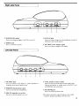
Front Panel
1':: Display
The display show\ vital information for operating the
70 10.
(6:FFFECT MODULI-.key
Q In Play mode
Serve>to hn4tc.h indiuiclual cfl'cs~module on and off.
i ) In Edit mode
Sent\ to cal l mtrdules and paramstcrs to be
STORE key
comted.
S e n m to store a patch.
:r;lEDIT key
(7:
USERtPRESET key
Serves to switch between Play mode and Edit mode.
T h i ~key scrveh to stop storc operation too.
Serves to .switch [he group c ~ patches
f
to call.
@ PATCH 1-4keys
. 4 ) TOTAL key
Serve\ to call u \etling such
Servc to switch thc p;rtcli~.s.
;IS
patch lcvel o r name
exccpt for Effcct in Edit tnode.
$2 VALUE
+ / - keys
Serve tn change the valuc of a setting.
3
@ RANK A / V keys
Scrvc to switch banks ofpnlche. to call.
1
Right side Panel
8 POWER ON switch
:B
MIX IN jack
Serve\ to connect outpul from the headphone terminal of
CD players and cassette players.
Serves to [urn power supply of the 7010 on and ofC
INPUT jack
Seri e, to connect (he p i l d r .
I
c$] DC INPUT (AC adapter) jack
Serve5 to conncct a supplied .C
adaptcr.
Left side Panel
3 ) OUTPIITjack
Serves to connect to the input of a guitar amplifier or
recording mixer.~stereospecitication)
( 4
VOL. (master volume) knob
Serves to adjust the find outp~itvolume of h e 7010.
A d j u ~ t sthe speaker or output sound of OUTPUT jack
and PHONES jack conimonly.
,?
:.Q PHONES [head phones) jack
Serves to connect stereo headphones.
31
SYK ON (speaker on) switch
Serves to 5witch thc speaker on or off.
1.5; KBMOTE jack
Serves to connect optional FC02.
%For battcry activa~ion,open the battery cover. install
batteries propcsly, and tirn~lyclose the cover.
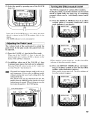
d When monitoring the sound
(4)
through the audio speaker
on the 7010.
push up t h e SYK ON switch up to t u r n off
(sound offl the speaker.
('5) PI-ess the YOWEK ON switch to turn o n the
power supply.
:.l:Open the speaker citl~inet.
lhc open \ w ~ t c hand
Holdmg !he 7010 hody d c .
pull the spr~kercahinc~up.
(Sound on) the speaker.
2
1Connect an electric guitar to the INPUT jack.
I::<
.
( 6 1 Push t h e SPK ON switch down to t u r n o n
(2)
Adjust the volume while playing the guitar.
Turn down the volume.
J When monitoring the sound
by headphone with a CD
source.
1 4 , Turn down the volume.
c51 Push up the SPK O N switch up to turn off' the
speaker.
('Connect
1: head phones to the PHONES jack.
( 6 : Press the POWER ON switch to t u r n on the
(2' Connect a CD player to the MIX INjack.
power supply.
The M K IN jack is coinpatiblc with thc stcrco input.
Connect by using a cable with a stcrco plu,o.
'1,;
Adjust the volume W-hilcplaying the guitar.
-
( 3 . Connect an electric guitar to the INPUTjack.
CD PLAYER
l.---..
,(\
-.
.a'
+,,&
\F
\
-
-
p
-
-
1
t t m
-,'
JWhen monitoring the sound
through a guitar amplifier
Connect an electric guitar to the INPUT jack.
A
J,) Connect a n electric g u i t a r amplifier t o the
OUTPUT jack.
P
(3Press the POWER
O N switch to t u r n on the
power supply.
$(1
Adjust the volume while pliiying the guitar.
*
Turn down thc volunic.
:E)
Push the SIJK ON switch u p to turn off (sound
off) the speaker.
JWhen connecting to a
cassette tape recorder.
Push the SPK ON switch up to turu off (sound
off) the speaker with the knob up.
13
Open the speaker cabinet.
Prcss the POWER O N switch to turn on the
power supply.
Iloldlng the 7010 body vile\,
pull the .pc&cr cabmc[ L I ~ .
Ihc open swltcl~a d
(2Connect an electric guitilr to the INPUT jack.
13Connect
the INPUT jack of the cassette tape
recorder to the output Jack of 7010.
13Turn down the volume.
P u s h t h e SPK O N switch down to t u r n o n
(sound on) the speaker.
1
8 Adjust
the 7010 output volume, and the input
volume of a cassette tape recorder, to a suitable
level while playing the guitar.
JWhen connecting a foot
controller.
..$l
off) the speaker.
REMOTE jack.
,.epress
the POWER ON sw-itch to turn on the
power supply.
Connect an electric guitar to the INPUT jack.
(zAd.just the volume whilc playing the guitar.
(3Connect the optional foot controller FCol to the
n
(3Push the SPK O N switch up to turn off (sound
Connect a guitar amplifier to the OU'I'PUT
jack.
:BTurn down the volume.
*
,2lrrke slrre thut the power supply of the 7010 is
turned off before cotztiecti~zgthe foot cotrtroller
FC02. If the punter s ~ i p p l jis~ on when cottnectitig,
the foot cof~troller
FC02 may not work properly.
.
&
JWhen connecting an AC
adapter.
The 7010 can be powcrcd by either an AC adapter
or 6 alkaline batteries(l.5V).
Under batter: power, t h e 7010 can w o r k
continuously for approximately 4 hours of normal
use.
.
Guilar
(3:)Connect the supplied AC adapter to the DC IS
jack.
Then connect o~herequipment m acquire conditions you
wiih.
1
AC ADAPTOR
This operation manual describes the 7010 using
plain words. considering heginaers. However. the
7010 contains some special terms which are not
used for a comp;ict cft'cctor.
This chapter c1cscril)es some spcciid terms for the
7010.
JEffect Module
The 7010 incorporntcs six el'lkct blocks which arc rcferred
to as "effect niodule". Each cffcct nodule can he thought
of as a single compact effect. The 7010 therefore operates
like six compact eflects connected in herics.
The follo\cing six types of cffect modules are available:
9 COhIP(COhIPKRSS0HI
JBank
The 7010 call4 up patchc.5 In set\ of four. Each set of four
patche\ is referred to a4 a "bank"
GROCP
RANK NO.
P-ATCH NO. I
0
An effect which cornprew. thc hound.
0 1V.4H
1
Effect \vhich periodically rcvls2s the sound quality.
3 DIST(DISTOUTI0N)
A distortion elTect uring analog clip circuit.
.,
3
USER
0 EQ(EQUAL.IZER)
3
4
An effect which revise> quality ofthe sound.
Q klOU( h.1OL)ULA'I'lOh-)
5
A modulation cfTcct which periodically change< the
wund quality to give the sound thickness.
Q UE\'Il~l,Y(UIIVICKI~/I~IEII~~l')
A reverb effect which crciltes the spatial sound.
JEffect Type
Each effect module contains s c v c r i ~ leffect variations
which are called "cffect types". An ~ ' f f e c tnlodule can
normally use o n l y o n c e f f e c t t y p e at a tirne. T h e
DlSTORTlON module utilizes ZNR(ZOOh4 Noisc
Reduction~inaddition to the di\to~tioncffcct. For ri list of
effect types in each effect moduk. ple:t.,e w e the tahle on
page 17.
PRESET
J Parameter
The elements which determine the ~ o u n dand name cif an
effect a n refcrrcd to as "parameters". Pariimzter values
~ , cri';ite your own
can Ix adjustcd for each efkc't ~ n i i d u l to
patches N ilh thc 70 10.
JPatches and Groups
A combination of cffcct modules. each with individual
paramcler settings plus thc final iwlurne level settings,
ampliticr siniulatc~rscttinps and 11iln1t:is referred to as a
"patcl1".
T h z 7010 has two 111e11lo1.y
iircils o r "groups" where
piltche~are stored:the USER group fix patches that can be
altered by thc usa., a r d t l ~ cPRESET gruup li)r read only
patches. There are 34 patchc\ in the USER group and 40
patches in thc PKESL3' group. I;w a tc~talof h4 patches.
T h e functions ol' the 70 1 0 L-an hc divided inro rhree
d i f f e r e n t categories. T h c h c a r e called " m o d c s " . its
described hclow.
Q Play ,\lode 1 I'lease refer to page 9 )
In this node, patche\ arc selecrcd and playcd. This i\ the
default modc \ v I i c ~thc
~ powcr supply i \ turned on.
Q Edit Mode (Ple:~serefer to pirgc 13)
In this modc. thc pnrametcr\ ul'ci~chp ~ c can
h be cdited.
OSpecial hlotle (Plcase refer to pilgc 20)
Serves t o relurn all parch data to thc' fxtclry preset
The play mode is basically to play using the stored
patches. The play inode also can select patches,
adjust volume, turn the effect modules d o f f and
do tunings.
/
5: Effect module odoft'
Thc effcat indicator lights to >hot\ which effects are
currently on foi a y v e n patch
21
,
3
Turning on the power supply
(1) Make sure that the power supply of the 7010 is
turned off before connecting an electric guitar.
When monitoring with a guitar amplifier. makc sure
that the guitar arnplitirr is turned off beforc sunnecting.
I Selecting a Patch
(1)Select the group with the USERPRESET key.
(2)Turn on the 7010 power supply.
When mot~i~oring
by a guitar amplifier. thcn turn on Ihc
guitar amplifier.
Choose thc group from which you want to select a
p w h . by pi~shingthe USER PRESET key.
(2) Select the bank with the BmK A / V keys.
To protect n guitur amplifier speaker, timzing q f i
the power rrrppiy. f i r n r?fl *Ire guitar o~tiph@r
first.
(3)Adjust the volume while playing the guitar.
I
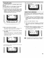
Panel Display in Play Mode
I
When the 7010 is turned on, the unit automatically
goes into Play mode. I n t h e Play mode, t h e
following information is sho\vn on the display.
(I
Patch name
The currently selected p a k h name is >hown.
!?,:l
Group ( USERPRESET)
The froup where the currently selectcd patch belongs. is
shown.
3 )Rank number
The currently selected bank number ic shown in the
BANK field.
Patch numher
The currcntly selected patch nuinber is shown in the
PATCH field.
With each press of the BANKAkey. thc next higher bank
is selected, and w ~ t heach press of the BANK V k e y . the
next lower bank. At hi< time, the bank number flashes.
( R a n k number continues flashing until the patch i;
zelected. I
m
Merely pressing the B A N K A / V k e y does nu?
select the pntch.
To actirafe the patch, press one of the PATCH
keys 1 4 , ns described helow
1 Turning the Effect module ordoff
(3) Select the patch by pressing one of the PATCH
keys 1-4.
The 7010 is composed of various effect modules.
In the play mode, each effect module can be turned
adoff by hand easily the same way as continuous
compact effects can be individually turncd onloff
by foot.
( I ) Press the EFFECT MODULE key of an effect
tnodule which is currently turned off. (effect
mode indicator is not shown)
Press one of the PATCIH keys 1-4 tu srlcct the p;~tcIi
which is s h o w n in the P A T C H number field o n the
display.
(The BANK indicator is now constantly lit)
1
Adjusting the Patch Level
1
The volume level of the each patch is called the
patch level. In the play mode, the patch level can
be adjusted.
( 1 ) Press the VALUE +/- keys in the Play mode.
When o n e of the VALUE t/- key\ i x p r e \ w d . the
current patch lcvcl scttins (0-99) is \hewn on thc
diiplay while LEVEL i\ indicated.
(2) In addition. when one of the VALUI3 +/- keys
is pressed once more, the level can be adjusted.
Effect module i s now rurned on. At ~ h i ctime erfect
indicator of that cffect module i s shown.
P r e s s i n g VALUE + key increabes thc v a l u e a n d
przssing V A L U E - key decreases it.
(2) Press the EFFECT MODULE key corresponding to on-effect tnodule to turn off that effect
module. (effect indicator is shown)
The patch l e ~ seninp
d
c b o ~ i ~rmde
e s in this a v y is
only temporary. If you select a diJ/f'crentpatch
without storirlg the new level setting first, the
setting will be lost.
The patch level car1 be adjusted also for the
patches front the P M S E T groiip, but the rlew lewI
setting ctmmot be stored. \'C7ze11wishiug 10 smre the
level, store tltc patclr in thc CiSER group.
Effect modulc is now turned off. The effcct indicator of
that efrect module disappearh.
I
Bv~assina
the Effects
You can temporarily turn off all effects in a patch.
This status is called "IiYI'ASS". It is useful for
checking effect drive.
( l ) In the Play nlode, press the PATCH key whose
nuniber is the silnlc as the patch n u m l ~ e rwhich
is currently sclecterl. ( I t is indicated in the
patch field on the display.)
For exnrrrple, i f the pfrtclr rlurrrber S ~ I O H V I U J Z the
displajl is '2', prcw /'A Wll 2 key to bypass.
(2) All effects in the patch a r e bypassed and the
original guitar sound is heard.
The display shows "BYPASS" at the same time the
PATCH kcy is pressed to indicate that bypass has bccn
selected.
"BYPASS" is indicated for O I I C seccind, then changc
into tuner indication (if there i h no input from y i t a r ,
the display \bows'-' ) thc 13t'PASSTTUKEK indicalor
also lishts up.
I
Muting the Output
You can temporarily rnute the entire output from
the 7010. This stiltus is ci~llcd"MUTE". It is
useful f o r e s a m p l e when wishing to t u n e a n
instrument on stage.
(1) In the Play n~otle,press the PATCH key whose
number is the siinle ils the currently selected
patch numbcr for one seconcl. (It is indicated in
the patch lield on the display.)
Fur exanrplc, i f the pntclr rrrrrnher slrowrr on Ilze
display is $2: p r t w tiw !A
' TCH 2 key f i r nt least
orw secorrii to nlrrte the or1tput.
(2) The output tone is completely muted and the
sound of the guitar cannot be heard.
AI the moment PATCH kcy is p r c w d . The indication
"BYPASS" appears first o n thc display. but if the key is
pressed for mnrr than one sccond. the indication chanse
to "hUJTE" tu indicate that thi. output has becn muted.
Thc indicarion s h o w for one second, then switches to
tuner indication (if thew i h no input from guitar. the
also BYPASSPTUKER indicator is
display s h m w
I-')
To niuke the explaautio~rensier, it is described tlrnt
"Urigirial sourrd" irr ttrc iiyprrss corrditiotl.
However, digitcl1 procwsirrg of irrprrt torre executes
both in the effect orr rrrrd qnect olf cotrditiorrs. So
it will trot b e L ' X I I C I I ~ Ilre snrrre a s when direct(y
plz~ggirrgtire glritar into the a~nplifier.
(3) To return to the P h y mode, press the same key
again o r select another l ~ t c h .
I
shoivn.
(3) To return to the Yhry mode, press the s i ~ l l ekey
Tuning the guitar
Whrn puide marks appear on both cides of the note, the
string is tuned correctly.
The 7010 incorporates an automatic guitar tuning
function.
When the 7010 is set to the bypass or mute mode,
the tuning function is automatically enabled.
(l) In the Play mode. press the PATCH key whose
number is the same as currently selected patch
number (It is indicated in PATCH field on the
display) to activate the byptiss o r mule mode.
The BYPASSmUKER indication lights.
1 Guitar Tuner Calibration
The reference of the integrated chromatic tuner
can be adjusted Tor t h e frequency of n ~ u s i c a l
interval A.
( l ) In the Play mode. press the PATCH key whose
number is the same a s the currently selected
patch number to activate the bypass o r mute
mode.
(2) Press one of the VALUE +l- Keys.
(3) The current reference frequency of musical
interval A is s h o r n for a brief duration on the
display.
(2) Pick an open string on the guitar.
T h e diqplay F ~ O ~ Cthe
F note which ir closect to the
current pitch. Tune thc gultar to thc desired p~tch.
(3)While the reference frequency is shown, use the
V.4l.UE +/- keys to adjust the frequency.
The adjustment range is 135Hz to 415Hz. This is
s h w - n on the display as "35-45".
(3) The display shows the desired note. perform
fine tuning.
While the tuner f u n c t ~ a ni\ an. the effect indicator
w o r k as a tine tunins meter. If the pitch is too high,
the REVIDLY indicators light, if it is loo lam. the
COMP indicator l i ~ h t s .
The defiullt reference Jkcquency setting that is
esfablirhd when the 7010 is N n d on is AfOHz.
A puidc mark (<l is shown a> [he pitch of [he s t r i n ~gets
cloqer to the displayed note.
PHONES
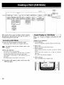
Edit mode allows you to adjust effect module
p a r a m e t e r s , p a t c h level, a n d patch n a m e t o
compose the patch as you will.
Activating Edit Mode
(1 Select the desired patch in the Play mode.
I Panel Display in
(1)EL'fectType indication
(<Tl
TYPE Indicator
Indicate the parameter currently edited is the effect type.
Both yroups, User or prescl, are avriilablc at this time.
For detnils
to y nge 9.
011 how
to select n Patch. plense refer
The 7010 is now in thc Edit Mode.
AL this time, the parameler a n d the value (VALUE)
currently being editing are iridlcated on the di\play.
Panel display in edit mode is a little different from the
play mode.
For further details, please refer to next section.
(31 To return edit mode to play mode, press the
EDlT key again.
Effect TJ-pe
Indicate< the name of the selcctcd cffcct.
3 I EfTect l~idicator
ECfecl module indicator currently selected for editing
fla41es.
About other effect niodulcs, if it is ON. the indicator
I1ghts up.
If is OFF. the indicator disappears.
@I
4
(2) Press the Edit key
Edit Mode
There a r e 3 kinds of display indications in edit
mode.
EDIT Indicator
Show, that Mode status is EDlT mode.
(2) Effect Parameter Indication
5:Individual Parameter Type
Effect paratnctcr name is ind~cated.
:2)
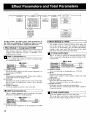
I Editing Effect Parameter
( l ) Press the EDIT key to activate edit mode.
Parameter Value (VALUE)
The current parameter value i s indicated.
Effect Indicator
The indic;itor of the effcct module currently sclec~edis
flashing.
C4;
EDIT Indicator
It shows that mode status is EDIT mode.
(3)Total Parameter Indication
:1'1TOTAL Indicator
Show5 the parancter currently edited is a total duty
element (total parameter) in he composition of the
selected patch such a i patch lewl and patch name.
This ~ndicatoris flashing.
Total Parameter Type
Total parameter name currently edited i s shown.
However, patch name is sho\vn only for patch name.
(2) Select effcct rnodule you want to edit wit11 the
EFFECT MODULE key.
3 Parameter Value (VALUE)
Pari~nietervalue currently ielected Cor editing i h ihoxvn.
& Effect Indicator
If the cffcct module is on, the indicator light5 up.
g:EDIT Indicator
It s h o w that mode status is EDIT mode
Effect type in the Effect module currently edited is shown.
then effect indicatur flashes.
1Vhetr the selected effect module is OFF, 'EFX
W7ze11you want to turn on an effect nrodrrle whicft
OFF, press t l ~ eVrlLLrE + key. On tile displuy
'EFX 011'sirows.
w s
(3)Editing in the selected Effect module
To call Parameter, press the responding EFFECT
MODULE key several tirnrss.
Every time you press the EFFECT MODULE key. a
different parameter and corresponding value is shown
on the display.
(3) Press the EFFECT MODULE key corrcsponding to effect module which you want to turn
off.
(4) Press the EFFECT MODULE key several times
to indicate 'EFX On' on the display.
( S ) Press the VALUE- key.
Effect nloclule is no\\ turned off.
- You can call paratneter
2,;
wirh the BA!VK A / V
keys.
( 4 i Change effect p a r a m e t e r value with t h e
VALUE +l-keys.
For the kiftds atid f~rnctionsof each parameter in
effect niodrtle, please refer to !Effect parameters
and Total parametens] olz page 19-24.
--
@
Editing in this nwy is only tenrpora~y
I j ' y o , select LZ din,,ttt patch witltout storing the
editedpatch, it win retzmt to the value before edit.
For storing t h e patch, please refer to t h e
descriptio~ron page 16.
dH.
ibu n t l turn an eflecf nodule on and off with
L'SEWPRESET key.
I Editina Total Parameter
(1) Press the TOTAL key in the edit mode.
iFFECT BLOCK D
l
~
4
/
~
o o e -
I Switching Effect Modules on and off
In edit mode. each effect module can be turned
on/off independently.
(1) I n the edit mode, press the EFFECT MODULE
key corresponding to effect module you want to
turn on .
EFX OF' is shown on the display.
(2) Press the VALUE + key.
Effect module is now tt~r~icd
on.
Total indlcator is tlashing at right 4 e of EDIT indicaror
on the display. It indicates total parameter can be rdited.
~
(2) To call parameter you want to edit in total
parameter. press t h e T O T A L key several
times.
-
Evcry time you prers thc TOTAL key, thc currently
selrctcd paramCtcr type; and valucs ar? rhown on thc
display.
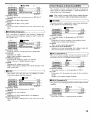
To stop the store standby condition, press
EDIT key.
1611can store in tlre Play ~twde.
(2) Designate a patch to store.
To deslgndte a patch. firit choose the bank. number w~th
the B A N K A / Vkeys.
Then. s p e c ~ f ya patch numbcr with the PATCH 1-4
keys.
Patches cannot he stored in the PRESITT ~ v o u pIf.
a patch is c/to.sert from the PRESET group, tlre
store destir~atiorl will nuton~aticallybecome the
USER groap. Specifi a bank and patch r~rimberin
the IJSERgroup.
Yon can call parameter with the B.4,Vh' A / V
k(>yy.
(3) If no store destination is specified for a patch
selected from the USER group, the patch will
be stored in the original location.
(3) Change total parameter value with the VALCE
+l- keyS.
If nu \~trrvdestination
specified for a patch selected
from the PRESET group. the patch will he stored in
"01" of the USER group.
='
G?!
!@
="
L..$<
Setting the patch name as a part of totd paranwtcr
is possible.
A palch name of up to 6 letters can be entered.
Change each letter with the VALUE +/- keyv,
Press the T01:4L key wlrenfinished.
A"!?'
For total parameter types (ind the ~ I I I I C ~ ~ Uplease
II,
rqfer to [Effect puranreter and T o t d purucrrneterl olr
page 17-22.
Wlten a patclr is stored, t h e patch t h a t was
previously stored i n that number will be
owrwritter~arrd cannot be recovered. However, it
is possible to restore all factory preset patches. (not
irrdivid~mlpatches) For the method, please refer to
[Retrrrrtiirg t h e 7010 to t h e factory preset
condition (Special Mode)] on page 26.
( 4 ) To editing effect pararrwters continuously.
press the EFFECT MODULE key in the effect
module which you want to change.
&IN! Press the EIIIT key to retrrrn to pla~lntmde.
I Storing a Patch
1
If an indicated patch is not stored, the change will
be lost when another patch is selected.
To preserve a setting. store the patch ;is described
below.
(1.1Press the STORI' key in edit mode.
This ;~cii~aies
thc store standby condition.
l
(4) Press the STORK key again.
..-....,...
..
Patch
I1
DIST 1 LEAD 2
,
.. ...........-...--.---.--.---..----
.. .-...-..-........--.....
I
1
I
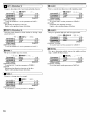
1 Effect Module 2: WAH
In this section, all el'fect types and parameters of
thc 7010 are explained. Parameters that are same
for several effect typesare explained minimum.
I Effect Module 1:Compressor(C0MP)
TOTAL
I
This module contains 3 kinds of effsct types which
c o m p m s tone input from a guitar. to maintain a Ie\.el.
uniform and even sound.
I
This module contain 4 kinds of effects which adjuzt the
tone of {he sound over time. This nlodule can be placed
right before or immediately aiter thc DIST (Distortion)
module. in the signal path. The placenirnt in ~ h csignal
path affect1 the tone color or the tinal sound.
1
AT WAH (AUTO WAH)
1
This is m eifect in which the stressed frequency rangc
moves up and down depending on dyn'miic (strong. weak)
cd guitar tone.
COMP l
Parameter 1
SENS
0-10
Parameter 2
ATTACK
0-10
Effect onloff
ON/OFF
t 1) EFFECT TYPE
Sclccts the effect 1ype.To irsc the riorn~alconiprcssor. set
the parameter to 'COMP 1 '.
(2J SENS
Determines the coniprcssor depth. Higher ~ a l u c prodi~ce
i
more uniform level and longer sustain.
(3) ATTACK
Determines the time lag between [he y i t a r sound Input
and the onset of comprcssion. Lower \ d u e \ produce
faster o n m .
(4EFFECT ONfOFF
To use h e module. turn 11 on. If not. turn it off.
Parameter l S E N S
0-10
Parameter 2 DIR(DIRECTI0N)
0, 1
Parameter 3 POSIT(POSITI0N)
0,1
Effect onloff
ONOFF
( l I EFFECT TYPE
To uii- the auto wah. set the parameter to 'AT WAH'.
(2! SENS
Detrrminr\ h e auto wah sensitivi~y.
Higher valucs produce wider ficquency range with small
guitar input.
(3)DIR (Direction)
Detcmmines the tone change direction
The \tre.\ed frcqucncy move\ up at 0 and down at 1.
(4) POSIT ~Posiiion)
Determines the e i f e c ~module enterins position.
The effect module is entered right hrtbre DIST module at
0 and r i y h ~aflcr iiI 1.
I
COMP l@ompressor 1)
p
Thi\ is a normal type colrlpre,\ol- which is used generally
as a comprcssion effect.
1 H COMP 2 (Compressor 2)
1
This is a bright coinpressor which accentuatrs the higher
freqnencies. Suitable for rhythm p;~cking.
Parameter 1
SENS
0-10
Parameter 2
ATTACK
0-10
Effect onloff
ONIOFF
(l! EFFECT TYPE:
T o use the hri~litcompressy. set thc pmmeter ttr 'COMP
I
1
PH WAH (PHASE WAH)
To use this niodulc. Nrn it on. if not, turn it off.
This is an effect which add> a phacs shifted tone to the
direct tone and c hanges the phase shift ovcr tirnc.
m P H WAH
I Effect Module 3:Distortion(DIST)
c
This nrndt~lr,contains W K (Zoun~original pruduct
noise redrrrtio~r)Adjrist it deperld~kgon the guitnr.
I
I
RHYTHM
Thi. gives cool drivc sound which m n t r d \ bass and strcsse\
trcblc. Suitable for rhythm basking or blucs.
RHYTHM
Parameter 1
GAIN
1-16
Parameter 2
TONE
0-10
Parameter 3
ZNR
0-10
Effect ontoff
ON/OFF
( I ) EFFECT TYPE
To use the rhythm, set the parameter to 'RHYTHM'.
(21 (;Am
Deterrnincs di+to~.tionintensity of tlic overdrive circuit.
I-ligher value4 producc more distortion.
(31 TONE
I l l \ i\ a tone-control-type equalizer.
( 4 ) %NU(Zoom Naisc Heductian~
Reduces noiw when not playing. Set to hiehest value that
does not un nalurall cut the in5tlvrncnt wund.
I H ENHANC (Enhancer)
Thii is an effcct to emphasize the frequency bandwidth
determined by the frequency parameter and to rnake Ihe
tone contour clear.
ENHANC
EXPAND
FREQ(FREQUENCY)
SENS
POSIT(POSITI0N)
1-10
1-1 2
0-10
0,1
ONIOFF
( I EFFECT Tk'l'lr
To use the cnhmcer, set thc paranlcter to 'ENI IANC'.
(2.1EXPAND
Determinci thc width.
Higher values produce a deeper effect.
(3'1FREQ ~'Frequency)
Dctcrrnincs thc Srcclucncy range to he s~ressed.
I-ligher valucs strcss higher frcqucncy rangc.
I
1 0 OD l (Overdrive 1)
This gives natural sounding overdrive distortion similar to
that ochieved with co~~ventional
compact effects.
(4) SENS
Deterrnincs thc cnhancer sensitivity.
Higher values pnlduce deeper effcct of the enhanccr with
small ~uitirrinput.
ICFFECT TYI'E
To use the o ~ c r d r i v c1. <et the piaamctcr to 'OD 1'.
,) GAIN
Ikterrnines thc distortion intensity of the overdrivc
c~rcuit.
Higher value\ produce drepzr diqtortion.
)
I
STEP
This creates auto ;~rpeggioeffcc I by adding thc effect
hound U ith mndom tone color changes.
STEP
0-10
Parameter l DEPTH
Parameter 2 RATE
1-20
Parameter 3 RESO(RES0NANCE)
0-10
Parameter 4 POSIT(POSITI0N)
0, 1
ONIOFF
Effect onloff
( 1 ) EFFECT TYPE
To use thc step, sct the parameter to 'STEP'.
(2) DEPTH
Delermine> thc tone wriation.
(31 UATE
Dctermine4 h e cffcct ipeed.1 spccd of I n arpegglol
(4 I RESO (Resonance)
G I V ~the
S sound a charactm\tic tone. and stre\scs the
cllcc1.
I
'I'his modulc contains a total of 10 kinds of distortion
cfkcts. Such irs 3 kind of overdrivc. 2 kinds of distorticm, 2
kinds of fuzz. and 3 lead sounds.
(4) PEAK
Givei the sound ;I characteristic tone. and stressc\ the
effect.
Parameter l
Parameter 2
Parameter 3
Parameter 4
Effect ontoff
1
I
0-10
Parameter 2 RATE
1-20
Parameter 3 PEAK
0-10
Parameter 4 POSIT(POSITI0N)
0,1
Effect onloff
ONtOFF
( I E12FECTTY I'E
To u;e the phase
.et the par;rnwtcr to 'PHWAI l'.
I 2 l DEPTH
Detcrrmnc\ the phwe effect dcpth.
13) RATE
Determines the ph;l\e \wing xpeed.
I
H OD 2 (Overdrive 2)
'I'hii gives warm so~lndingdistortion sin~ilarto that of a Iulw
amplifier.
Parameter 1
Parameter 2
Parameter 3
Effect onloff
I I rlrk'FECT TYI'I
To use the ovcrdrivc
GAIN
TONE
ZNR
1-1 6
0-10
0-10
OWOFF
7. set the paramctcr to 'OD 2'.
I
1
1 Iil LEAD 1
DlST 1 (Distortion 11
This 15 a rmooth tone distortio~~
wth expanding sound.
'This give; distortion with a hi~ssboost and solid chilracter.
P
=
Parameter 1
Parameter 2
Parameter 3
Effect onloff
GAIN
TONE
ZNR
Parameter 1
Parameter 2
Parameter 3
Effect ontoff
1-1 6
0-10
0-10
ONJOFF
(1)EFI;BCT TYPE
1-1 6
0-10
0-10
ONlOFF
EFI:ECT TYPE
To IIW the lead l . set the p;mmetcr to 'LEAD 1'
(21 GAIN
( 1)
'1'0 use the distortion I. set the paraneter to 'IIIST I '
i2)GAIN
Iklennine~the distortion inlensity.
Higher values produce deepcr distortion.
Dctcrmines the distortion intensity.
Higher values produce decpcr distortion.
I H DlST 2 (Distortion 2)
I
This gives hiud distortion sou~idsiniilar to driving a large
arnp to full level.
Parameter 1
Parameter 2
Parameter 3
Effect onloff
=OLEADl
GAIN
TONE
ZNR
DlsT2
GAIN
TONE
ZNR
g LEAD 2
+=
p
1
LEAD 2
This givcs grrinular high-gain t u l amp
~ type sound.
p
Parameter 1
Parameter 2
eter 3
Effect ontoff
1-16
0-10
0-10
ONJOFF
( l )EFl;RCT TYPE
To use the distortion 2. 9ct tlic paim~eterto 'DIST 7'.
GAIN
TONE
7NR
1-16
0-10
0-10
ONIOFF
( l EFFECT TYPE
'So use thc lead 2, set the p;lr:mlem to 'LEAD 2'.
I ID METAL
I
(il FUZZ 1
This givcs a modem type fuzz sound
Parameter 1
Parameter 2
Parameter 3
Effect ontoff
GAIN
TONE
ZNR
1-16
0-10
0-10
( 1)
To use the f u r / I.set the prameter to 'FUZZ l'.
t2)GAIN
De~crminesthe distortion intcns~tyof [h2 fu7/.
Higher values produce dccpcr d~rtortion.
FUZZ 2
This gives a vintage type fi~zi..sound.
FUZZ2
parameter 1
Parameter 2
Parameter 3
Effect ontoff
Parameter 1
Parameter 2
Parameter 3
Effect ontoff
ONfOFF
(1)EFFEC'I' 'TYPE
I
GAIN
TONE
ZNR
1
This g~vcsdistortion ~ h i c h
strcsses the treble and b i l ~ ~
rangc, witahle for heavy metd.
1-16
0-10
0-10
ON/OFF
( l JIWFECTTYPE
7'0 usc the fill7 2, set thc p ~ x ~ i i c ito
c r'FUZZ 2'.
METAL
GAIN
TONE
ZNR
1 -16
0-10
0-10
ONIOFF
EFk'IX'T TkTE
To u x the metal, set the par;mcter to 'METAL'
1 Effect Module 4:Eaualizer(EQ)
. .
I
I
I
I Effect Module 5:Modulation (MOD)
Thi< module contains 2 kinds of cffcct types which control
the sound tone.
I
4EQ (4band equalizer)
I
CHORUS
This equalizer ;~llowshcwst or cut in the presence super-
P a r a m e t e r 1 PRES(PRESENCE)
-12-12
P a r a m e t e r 2 HIGH
-1 2-1 2
-1 2-1 2
P a r a m e t e r 3 MID
P a r a m e t e r 4 LOW
-12-1 2
1-30
P a r a m e t e r 5 LEVEL
Effect ordoff
ONIOFF
( l )EFFECT TYPE
To use the 3 band equalizer, set the p r a m e t a to '4l.Q'.
(2)PKISS t Presence l
Adjusts the range of hlinno~iicsand overtones of a guiti~r.
Higher values producc more strcss o n the range of
hannonic: and ow~tones.
t31111GII
Adjusis the treble range.
Higher values produce more streks on the trcblc range.
t4)MlD
Adjusts the midrange.
I-ligher values produce I1ior.e \Ire<\ on the rnidr:~ngc.
--
-
(5)Imlv
Adjusts thc bass range.
Higher value; producc niore emphases on the 1u\~
range.
(6!I,EVEL
Adjusts the output level li,r EQ module.
I a 2 P EQ (2 b a n d p a r a m e t r i c e q u a l i z e r )
This 2 band parametric equalizer allows etting thc center
frequency range, boost and cut.
1-16
p a r a m s i r l HlGH F(FREQUENCY)
P a r a m e t e r 2 HIGH G(GAIN)
-12-12
1-16
P a r a m e t e r 3 LOW F(FREQUENCY)
P a r a m e t e r 4 LOW G(GAIN)
-1 2-1 2
P a r a m e t e r 5 LEVEL
1-30
ONfOFF
Effect onloff
I l IlCFFECT TYPE
To uw the 2 band parani.tric equalizer. set thc parameter
to '3'
EQ'.
(2)HlGH FlHigh freque~lry)
I>eter~ninesthc c r n k r frcqurnc), of the treble range.
I-lighcr values producc hipher centcr I'requency rongc.
(3)IIlGI-I C. (High gain1
Adjwts the treble rangc.
Iiighcr value; produce Inim strcs, on the trcblc rangc.
(4 11.0W F !Low frecprnry
Dctern~inci.Lhr center frcquency of thc bass mnpc.
lfigher values prmlucr highcr center frequency ransc.
1511,0\V G (Low-pain)
Adjusts the bass range.
lligher values produce niorc: stress on bass range.
I
Thik cft'cct module conti~in. 6 kinds of effect type< which
chanec tone timewise and rivc charactcr.
AIIeffect sound with periodically changing pitch is added to
the direct sound, for rich ambience.
Parameter 1
DEPTH
0-1 0
Parameter 2
RATE
1-20
MIX
0-10
Parameter 3
Effect onloff
ONIOFF
( lIEFFECT T Y P E
Select the effect type. To u w the chorus. set the paramctcr
10'CHORUS'.
~INYTII
Ik~crminesthe nioclulatiori depth.
(3)KATE
Detcnninei. the modulation rate.
14hllS
Ilctcrmines the ~ i g n a lIcvcl fed to the mixer circuit
between the output of the EQ module and the Input of the
IZEVfDLY module.
I
FLANGE ( F l a n g e r )
An cffcct sound delayed by several dozen milliseconds is
added to the direct sound, and the delay is periodically
changcd. rcsultinp in a strong flange effect.
FLA
Parameter 1
DEPTH
0-1 0
Parameter 2
RATE
1-20
Parameter 3
F B (FEEDBACK)
0-1 0
ONIOFF
Effect onloff
( l ) EFFtCT TYPE
To usc thc flanger, \et the p;~ranleterto 'FLANGE'.
(21 FH (Feedback)
Dctennines the amount of kcdhack, i.e. the proporticin of
the +gal routed hack to the input of the effcct circuit.
Incrcasing this parameter will result in a flange with very
pr~rrio~~nccd
character.
Thi\ cffcrt allows c h a n ~ i n gthc tone periodically.
Parameter 1
DEPTH
0-1 0
Parameter 2
RATE
1-20
Effect onfoff
ONlOFF
I I )I~FI;ISC"I'
mm
To use the tremolo. \et [he p;ir;~~iieter
to 'TREMOL'.
t21L)IIl'Tti
I)ctcrrnlne\ h e depth of trcrnolo cffcct.
(31RATE
Dztcniiines thc rate of tren~oloeffect.
1
/
RING M (Ring modulator)
H SFX T (Special Effect Termin)
Setting portamenr or vibra~uproduces my.cterious qxice
sound. However. [hi; synthe4zer on14 pronounces wiihin an
octave.
This gives metallic sound with irregular harrnrmics by
applying special modulation.
P -
Parameter l DEPTH
0-10
Parameter 2 FREQfFREQUENCY)
1-20
Effect onloff
ONIOFF
( 1 ) EFFECT TYPE
To use the ring modulator-. set the parameter to 'KIKG M'.
I 2) IIBPTH
Determines the modulation tlcpth.
Higher values produce winiling metallic cound.
13)FltEQ 1Frequency)
Determine\ the modulation Ircyucncy range.
I)il'fc~entvalues changc nic~i~llic
sound.
1
DBL (Doubling)
Parameter l BASE
Parameter 2 WAVE
C-B
1-6
l I EFFECT TYPE
To use the special effect, set the parameter to 'SFX T.
121IlASI:
Detcr~ninesthe octave from which the musical interval
itarts.
(3)W . 4 W
W;IWcan be selected from 7 kinds.
WAVE 1:VALUE 1-3 Milt1 W a w
WAVE 2:VALCE 4-6 Bright W;ivc
At G I C ~ wave, higher values ;dlo\v synthesizer to play in
higher niusicd interval rangc.
( 4 ) Ia0R'1',1(Portamenti
Detcrnlincs the portarnent w e .
l51 VIRRA1'0
Dctcrniincs the vibrato depth.
16) ENV-I' (Envelop to pitch :~nlountI
Dctcrmines thc musical intcrval amount of changc.,
dending on picking strength.
I
I
An effect sound with short delay is added to the direct
sound. giving the impression of niultiplc periorrner.q playing
together.
Parameter 2 FB(FEEDBACK)
Parameter 3 MIX
Effect onloff
-
0-10
0-10
ONIOFF
(1 I EFFECT TkTE
'To use the doubling, set the parlulleter to 'DBL'.
(2) TlhIE
Detcrnlines the ~ h o nd c h y d ~ m t i o n .The value shown on
tho display multiplied by 10 is the delay in ~nilliseconds
The range is 0 to 100111s.
13) FIj I fecdlxick:~
Determines the arnounl ol' kellhllek . i.e. . thc proportion
of tlw signal routed back to thc input of the effect circuit.
(4.1 YIS
Determines the mixing ~ n t i oof direct sound and del;~ycd
soun J.
f Iigher values increase the ;~rnountof effect.
This guitar synthesizer to~lcfollows the inputted nlusical
i ntcrvd.
This effect works hest when playing sirrgle note
lirr es.
Lrsirrg this effect witlr fire delay o r the revcrh
prodrices more spaliul eflect.
In this effect, the sy~rthesizcrtone and tlre grritar
tone with ring t~rodulutior~
are mixed to outprrfs. To
trrrn off tire guitar torre, set COMP modrrle, \):A H
module, und DIST nrodrrle ofJ and set output level
of EQ nmdrtle to I .
I Effect Module 6:ReverbDelay (REVIDLY)
I
I
HALL
I
LEVEL (Patch level)
Determines the level of each patch.
Parameter l
I
AMP SIM ( A ~ simulatorl
D
I I ) VALUE = 0
Amp simul;tto~off
(21 VALLX = 1
This produces the output character of a lOOw combo amp.
(3 VALUE = 2
This produces the output character ol' a by bright amp
which trcblc is stressed.
(4)VALUE = 3
Thiq produces the outpul character of a stack a m p
w ith 4 speakers.
1
PATCH NAME
Determine.; the name of each patch.
Parameter 1
TIME
0-10
TONE
0-10
Parameter 2
Parameter 3
MIX
0-10
Effect onloff
ON/OFF
I l) EFFECT TYPE
To use rhc room, set the parameter to '1100h.I'
I El DELAY
This is a conventional digilal delay effect with a delay time
of up to 420 n1illi:econds.
DELAY
Parameter 1
TIME( X 1Oms)
0-42
Parameter 2
F B(FEEDBACK)
0-10
Parameter 3
MIX
0-10
Effect ontoff
ON/OFF
( l )EFFEC'I' T Y P E
To w e thc delay. set thc parameter to 'DELAY'.
(2) TIME
Determine\ 1111:delay i n t e n d \ In 10m\steps.
( 3I FB (Feeclhack)
Determines the arnount ol tcedba~k.1.c. the propornon of
the signal routed back IO the input ol the elfect circuit.
Parameter 3
I
LEVEL(PATCH LEVEL) 0-99
This parameter simulates the output c1i:iracter of a guitar
amp.
I H ROOM
Thiq effect simulates a rooni with short reverberation.
I
Total parmctcrs except effect module among elements
compose a p;~tcharc contained.
This effect simulates s natilral hall. espansive sound.
Parameter 1
TIME
1-10
Parameter 2
TONE
0-10
Parameter 3
MIX
0-10
Effect ontoff
ONIOFF
( I ) EFFEC'I' T Y P E
Select the effect type.
To use thc hall, set the paranleter to 'HALL'.
(2) m m
Determines the reverb time.
Highcr values produce longer reverb t i ~ i ~ e s .
(3) TONE
Determines the reverb tone. Higher values p r o d ~ ~ c e
brighter sound.
(4) MIX
Determines the balance between dircct sound and el'fect
sound.
"0" nleans dircct sound only. and "IU" means niaxinlum
rcvcrb.
Total Parameter
P
P
This module contains 3 kinds of effects which add reverh to
sound.
(NAME)
( 1 , T h e follawirtg letters can be used.
I
Thc 7f)lO can be operated by battery activation using 6
LR6fA.A) alkaline dry battcrics I. 1 .W).Whcn connecting
the hC adi~ptor,the power supply route fro111thc hattcries ix
autilmatio;~llyilisco~inecteci.
JCautions for Dry Batteries
0 klakc w r c
111
use LR6(AA) alkaline dry batteries o r
l .5v.
Note if any batteries with different characlcristics arc
used. the company shall not d i e responsibility liw \afety
in r p m t i n g time or equipment.
0 Before rcpl;i~.ingbattcriss. turn clff thc p ~ ~ \ v c\upply
r
of
the 7010 irnd ionnccted equipments to prevent Janiagc
to the sp~.;~hi.r.
cc~nncctingequipment. o r patches l y
suclilc~ilyti~lving1111 powcr.
O T h e 7010 docs not have dry battery charging function.
Read thc prccuutions for dry battery beforc u\ing.
OTIIL. bnttcric> I i a \ ~two electrodes. The positi\.e I'+I
elec~rodc.which projccts out from the end of thc. hatter).
and the r ~ ~ - g i ~ telectrode,
ivc
which i \ flat. Install the
hnttcrics aicr)rclir~gto the indication. on the in.illc of the
battery cii.\LX.7'lic. 70 10 will not function it' the clcctrnde\
are not i n d l c d in the riyht direction.
When not u.\inp the 7010 for a long time. take out Ihe
battcrieh f r ~ r ~the
n bud) to prevent daniape by Icukay or
e x p h i o n of dry hatterie..
In saqe leakage of dry batterie5 occurs. thoroughly wipe
out the I ~ ~ l u in
i d ihe battery cace and the electn~clc.
Kcplacc thc batteries with ne\v one.. never rcu\e the
Icaked hattcrics.
d Use n c a hatt~.rics whcnever pussihle. Espcciallg if you
plan to use the 7010 liv a live pstl'orrnance.
It i > recomnwndcd that you use thc supplicd AC adapler
when u\ing the 7010 for lcmg periods of timc.
a
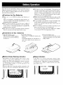
Jlnstallation of Dry Batteries
1-Open tlw Ixrttery cover.
Pull f'cmvard the 'OPEN' mark on
the battery c ~ ~ vine rthe 7010 hrrse
to remow it.
Z.ln~t;~ll
d r y batteries.
P l x c h piece5 of LR6(4A) alkaline. dry
battcries.
Indall them aligning the electrodes ol't
plus) and -(minus) to the iridicaticw in
l l l c;I>L'
~
.
JBattery Empty Warning Indication
When battcrics arc almost running down. hattcry crnpty
warning to urge battery replacenier~t i \ 41owr1on the
dicplay. Thc 7010 can be operated by h;tttcry activation
for approxin~ately1 hours of normal u w . In continuoui
u.c at m a ~ i m u mo u t p u t , it c a n b e o p e r a t e d for
3.Close the batter? cover.
I n m - t the tab Into thc hole on the
7010 and ali ~n the cover lo the 70 10
body to close.
Asleep Indication
I r the 7010 is I I O ~L I for~ more than 5 riiinutcs while
running cll'f of' ballcry power. the 71) 10 autoniaticully
switches into thz "Sleep status" to conacrvc the batteries.
To return to t h ~normal uhe status from the deep htatus,
p m \ any Le! oncc
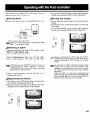
The optional foot controller FCO? enables patch wlcction,
bypass and mute of the 7010 by hot.
3, '1.0 clear the byp:~ssing. select another patch using the
IIAKK switch and the PATCH switch of the FCO2.
JConnections
dMuting the Output
QConnect the Foot controller to the REMOTE jack of the
1. Step on the pedal, whose lamp is lit for more than one
second.
2. The BYPASS lamp of the FC02 flashes to inform that
it is muting.
3. '1'0 clear the inuting, select another patch using the
ISANK switcl~; ~ n dthe PATCII switch of the FC02.
7010 using the cable of the FC02.
sure to turn off the power supply of the 7010
m+ Make
before connecting the cable.
&electing
a patch
I. S t e on
~ the RANK switcll of tile VC02 to select
i3
bank.
#l'"
L:SER group and P R E S E T group cantrot be
sn8itched by t h e FC02. Select it with t h e
USERPRESET key of the 7010 before operatitrg
patch selectiotr with the FC02.
2. Select a patch n u m b e r with t h e P A T C H 1 t o 4
buttoms of the FCOZ.
JBypassing the effects
l. The lamp aver the FC02 pedal which corresponds to
the currently selected patch will be lit.
2. Step on the pedal whose lamp is lit. The unit will enter
the bypass niode and the bypass lamp will light.
Remote cotrtrolling the 7010 using the FC02 is
possible only nl,en tltr 7010 i.5 in play nzode. Note it
cannot />c operated by the FC02 when it is in other
modes.
As described in "Other indication function Sleep
indica tion " o n page 23, if tone input or key
operation is trot operated-for nrore than 5 nrinutes,
the 7010 switclres to sleep status to save battery
dissipation.
W'heir the 7010 is in sleep statrrs, the bank # and
RYP-ASS la~npftrn off and the lamp indicating the
patch nunrber lights on in turn in the FC02. To
clear the sleep status, step once otr a pedal.
%ZNR (ZOOM KOISE REDUCTION) should be ridjasted for the guitar you use.
25
p
-
-
-
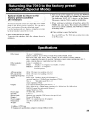
Special mode to return to the
factory preset condition
(All initialize)
p
2. T u r n on the power supply by pressing the POWLR
OR' svitch while keeping the STORE key depressed.
The indication "IIVIT AI," is shown on the d i ~ p l i ~ y .
This means that the 7010 is ready for 311 initialize.
p
All initialize function rcturns all 24 patches in the lKER
group to the factory preset condi~icm.Tlrii opCratitrn
l o o ~ c and
i rewrites all prtchek rditcd and ctored.
Usc thih function with cim.. hecnux all patches rc\vritten
by the all initialize cnnnor be recowrzd.
l. Turn IIITthe 7010 power supply.
To protect t h e speaker, t u r n t h e t o l r l ~ n edown to
minimum.
E f k r t types:
EfTect niodulex
Patches:
3. \+'hen wishing t o initialize all patches, press t h e
STORE key once more. This restores all patches to
their factory preset condition. The 70 10 then switches
to the Play mode.
O When wishing to cancel the function
Prchs the EIIIT key. The 7010 then s\vitcIies from ready
to the Play nrode.
IS I ni,~x.7 \ ~ n ~ u l t d n r o u \ ~
COh3II' I . COhl07 ALTO \\'-M.PI I4SE U AH. ENHrWCER. STEP.
RHYTlIM. ODI, OD2, DISTI. DIS1'2. FUZZ1, F1.27,. LEADI. LEADI, METAL.
4EQ, 7l'ARA EQ. CHOKUS. RANGER, TREMO1,O. RING-.LIOD, DOUR1,ING. SFX T.
HALL, ROOM, DELAY, AMP SIMC'LATOR. IZNR)
6 ( n u x 0 wnultanetru<I
6 bank4 u J = 24 patche\ (renrrtablr., \tnrabls)
USER
PKESICT I0 honk\ 4 = 30 p ~ t c h c \
Total h4 pntc lies
M)conversion:
18-bit 128-times ovcrcanipling con1 'rter
D/:\ conversion:
Sari~plingfrequency:
Input:
l 8-bit 128-times ovcrui~mplingconwrter
0otp11t:
Power amp:
Speaker:
Kemote jack:
Display:
Power supply:
Di~nensions:
W'i*igl~t:
\...
1.2:
31 2 5 ktiz
Guitar inpui Standard phone jack/ h'lonaural x 1
nominal input level - 2 0 dBml input impedance 171lk621
I
in
Mini phone jack/ Stcrco x I
(input impedance I OkSL)
Linc output S~andardphone jack/ Stcrctr s l
( m u . output Icwl + 5dBnd output i~nprdanceL= 1liQ or less. R= I kR or less)
PHONES nutput Mini phone jack/ Stereo s I
coutpur SOmW into 3 3 2 )
5W RMS 8!2. IOW PIi;\K
7.7~111s I
Optional ioot controller FCO2 connection special jack
Cu\ton~LCD display
DC9V I A I supplicd spccial ..\C ahplor)
222 ( W ) s 120 ( D ) s X0 (1.11
750 g
OdUm = 0.775Vrrns
S Ilesigns and spcrifications subject to change without notice.
L iSafety Precautions
QPower supply
3 Activation by the AC adaptor
Use the mpplied AC adaptor.
To prevent malfunction and daniagc to the unit, do not
use any other kind of AC adaptor.
Make aure to use the correct AC idapter for the line
voltage in your area.
When using the 7010 in an area with a different line
voltage, please consult your local Z00h.1distributor
about acquiring a proper 4 C adaptor.
When unplugging the adapter pull it from the adapter
body, not from the attached cable.
When not using thc 7010 for a long time, unplug the
AC adaptor.
Q Activation by dry batteries
Use 6 pieces of LR6(AA) alkaline dry batteries (1.W) .
Do not mix different kind of batteries for use. they may
be different voltage with the same Ibrn~.
Place the plus I+)
and minus ( - ) direction of dry
batteries aligning properly to the indicarion in thc
battery case.
The 7010 does not have a battery- charging function.
Read the precautions carefully to use dry batteries.
Do not mix new dry batteries and used ones for use.
When not using the 7010 for a long lime, remove the
batteries.
In case leakage of dry batteries occurs. thoroughly
wipe out the liquid in the battery case and electrode.
Close the battery cover when using the 7010.
3 Environment
Avoid using your 7010 in environments where it will
be exposed to:
Extremely high or low temperature
Estremely high humidity
Excessive dust or sand
Excessive vibration or shock
3 Handling
Since the 7010 is a precision clectroriic device. avoid
applying escessive force to it. Also take care not to
drop the unit. and do not subject i t to shock or
cxccssive pressure sincc this can rewlt in damage to
the unit.
Take care when opening or closing the speaker cabinct.
Do nor put any foreign objects (coins, wires. etc.) or
liquid (water. soft drink. etc.) in the 7010.
Do not cover the slit in the rear of the 70 10. since i t can
raise the internal temperature and cause malfunction.
0 Connecting cables to input and output jacks
You should always turn off the power to the 7010 and
all other equipment before connecting any cables.
Also make sure to turn off the power and disconnect
all cables and the AC adaptor before moving the 7010.
0 Alterations
Nevcr open the care of the 7010 or attempt to alter the
product in any way since this can rewlt in damage to
the unit.
I n case any damage occurs as a result of alternation. the
company shall not take any responhibility for it.
Usage Precautions
3 Electricd Interference
The 7010 is designcd to minimize electromagnetic
interference and emission ~Cslectromagneticwaves.
However. interference may occur if placed too close to
other electronic equipment. If such problems ocour.
move the 7010 way from the affected equipment.
Note that elect14cal equipment containing digitill
circuitry. such as h e 7010, can malfunction or suffer
data loss, due to electromagnetic interference.
0 1-ncating Position
Locate the 7010 in the flat position.
I C the 7010 is located with the speaker cabinet open in
sloped position, the 7010 rnay turn over. or the speaker
cabinet may suddenly clore.
0 Cleaning
Use a soft. dry cloth to clean the 7010. If necessary.
slightly moisten thc cloth. Never use cleanser wax, or
solvents such as cleaning alcohol. henzene, paint
thinner.
Q Danisge
Whcn the 701U is damaged or any error occurs.
disconnect the AC adi~ptorand other connecting cables
immediately.
l'lcase notify tlic "product type No.". "product No.".
"concrete condition of damage or error". "customer's
name, address and telephone No." to your local
cli\tributor or ZOOM dcalcr.
Plcasc Lccp this manui~lin a convenient place for future
reference.
ZOOM CORPORATION
NOAH Bldg., 2-10-2, Miyanishi-cho, Fuchu-shi, Tokyo 183, Japan
PHONE: 0423-69-71 11 FAX: 0423-69-71 15
Printed in Japan 701 0-5000