1
ふ
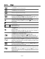
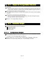
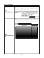
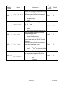
Check Weighing Indicator
WM : PD4000489
This is a hazard alert mark.
This mark informs you about the operation of the product.
Note This manual is subject to change without notice at any time to improve the product. No part of this
manual may be photocopied, reproduced, or translated into another language without the prior
written consent of the A&D Company.
Product specifications are subject to change without any obligation on the part of the manufacture.
Modbus is a registered trademark of the Schneider Electric Corporation.
Copyright
2003
Contents
1.
Compliance........................................................................................ 5
1.1.1.
Compliance with FCC rules ....................................................... 5
1.1.2.
Compliance with European Directives....................................... 5
2.
Outline and Features ......................................................................... 6
2.1.
Precautions.................................................................................... 7
2.2.
Front Panel .................................................................................... 8
2.2.1.
Keys .......................................................................................... 9
2.2.2.
Symbols................................................................................... 10
2.3.
Rear Panel................................................................................... 11
3.
Installation........................................................................................ 12
3.1.
Installing Options ......................................................................... 12
3.2.
Mounting the Indicator ................................................................. 13
3.3.
Connecting the Loadcell Cable.................................................... 14
3.3.1.
Verifying Loadcell Output and Input Sensitivity............................ 15
3.4.
Wiring the Power Cord ................................................................ 16
4.
Basic Operation ............................................................................... 17
4.1.
Key Operation Examples ............................................................. 17
4.1.1.
Standby Mode ......................................................................... 17
4.1.2.
Cursor Operation..................................................................... 17
4.1.3.
Inputting Characters ................................................................ 17
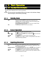
4.1.4.
Calling a Code......................................................................... 18
4.1.5.
Entering a Correction Mode..................................................... 18
4.1.6.
Entering The Menu.................................................................. 18
4.2.
Status Chart................................................................................. 19
4.2.1.
Mode Map and Menu .............................................................. 19
4.2.2.
Status of Weighing Mode ........................................................ 20
5.
Calibration........................................................................................ 21
5.1.
Actual Load Calibration (using a Mass) ....................................... 22
5.2.
Digital Span (Calibration without a Mass).................................... 23
5.3.
Gravity Acceleration Correction ................................................... 24
5.3.1.
Gravity Acceleration Reference............................................... 24
5.4.
Calibration Error .......................................................................... 25
6.
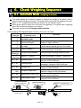
Check Weighing Sequence.............................................................. 27
Automatic Mode ( weighing in motion)......................................... 27
Conveyor Stop Mode................................................................... 29
Foreign Matter Detection ............................................................. 31
OK Mode ..................................................................................... 33
Manual Mode............................................................................... 35
Simple Mode................................................................................ 37
Status and Check Weighing Sequence ....................................... 39
6.1.
6.2.
6.3.
6.4.
6.5.
6.6.
6.7.
7.
Code ................................................................................................ 43
7.1.
Use of the Code........................................................................... 44
7.1.1.
Recalling a Code ..................................................................... 44
Page 1
7.1.2.
7.2.
7.2.1.
7.2.2.
7.2.3.
7.2.4.
7.2.5.
7.3.
Editing a Code in the Sub-display ........................................... 44
The Menu of Code Edit................................................................ 45
Edit .......................................................................................... 45
Search..................................................................................... 45
Delete...................................................................................... 46
Copy........................................................................................ 46
Preset Tare.............................................................................. 47
Recalling a Code ......................................................................... 48
8.
Other Functions ............................................................................... 50
8.1.
Zero Tracking Function................................................................ 50
8.1.1.
Static Zero Tracking Function.................................................. 50
8.1.2.
Dynamic Zero Tracking Function............................................. 51
8.2.
Judgement and Selector Action................................................... 52
8.3.
Loss-in-weight ............................................................................. 53
8.4.
Motion Compensation.................................................................. 53
8.5.
Detection Method ........................................................................ 54
8.5.1.
Detecting Front with Position Sensor ...................................... 54
8.5.2.
Detecting End with Position Sensor ........................................ 54
8.5.3.
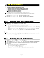
Detecting Gross Value above Zero Band ................................ 55
8.5.4.
Detecting Gross Value within Zero Band................................. 55
8.6.
Check to Forward the Article ....................................................... 55
8.7.
Duplication of the Articles ............................................................ 56
8.8.
Crush of the Articles .................................................................... 56
8.9.
BUSY Output ............................................................................... 57
8.10.
Stop Input during BUSY .............................................................. 57
8.11.
Output for Foreign Matter Detection ............................................ 58
8.12.
Evaluation Output ........................................................................ 58
8.12.1.
Comparison Output ................................................................. 58
8.12.2.
Output to Selectors.................................................................. 59
8.13.
Buzzer Output.............................................................................. 60
8.14.
Total Function.............................................................................. 60
8.15.
Safety Check Function ................................................................ 61
8.16.
Zero Operation ............................................................................ 62
8.17.
Tare Operation ............................................................................ 63
8.17.1.
Tare Clear Operation............................................................... 63
8.18.
Preset Tare.................................................................................. 64
8.19.
Customizing F1 and F2 key ......................................................... 64
8.20.
Customizing Sub Display............................................................. 65
8.21.
Graph Display.............................................................................. 68
8.22.
Canceling Last Judgement .......................................................... 69
8.23.
Clearing the Total ........................................................................ 69
8.24.
Error Message and Alarm............................................................ 70
8.25.
Graphic Status Indicator .............................................................. 72
8.26.
Memory Backup........................................................................... 73
9.
Interface........................................................................................... 74
9.1.
Control I/O Function .................................................................... 74
9.1.1.
Interface Circuit ....................................................................... 74
9.1.2.
Timing Chart............................................................................ 75
9.2.
Built-in RS-485 Interface ............................................................. 76
9.2.1.
Settings of Parameters for RS-485.......................................... 76
9.2.2.
Connection .............................................................................. 77
Page 2
9.2.3.
9.2.4.
9.2.5.
9.2.6.
9.2.7.
9.2.8.
9.2.9.
9.2.10.
9.3.
9.4.
9.4.1.
9.4.2.
9.4.3.
9.4.4.
9.4.5.
9.4.6.
9.5.
9.6.
9.7.
9.8.
9.9.
9.10.
9.11.
Timing Chart............................................................................ 78
Communication Modes............................................................ 78
General Data Format............................................................... 79
A&D Data Format .................................................................... 80
Address ................................................................................... 81
Command List ......................................................................... 82
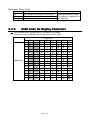
ASCII Code for Display Characters ......................................... 83
Protocol (Communication Procedure and Format) ............................. 84
Modbus Interface for RS-485 ....................................................... 91
Built-in Current Loop Output ........................................................ 98
Connection .............................................................................. 98
Communication Modes............................................................ 98
Data Format ............................................................................ 99
Settings of Parameters for Current Loop................................. 99
Print Format (Process Print) .................................................... 99
Time Stamp ........................................................................... 101
BCD Output of Option OP-01 .................................................... 102
Relay Output of Option OP-02................................................... 106
RS-422/485 Interface of Option OP-03...................................... 107
RS-232C Interface of Option OP-04 .......................................... 110
Parallel I/O of Option OP-05 ...................................................... 111
Analog Output of Option OP-07................................................. 113
Other Options ............................................................................ 114
10.
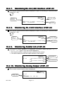
Maintenance (Monitor and Test) .................................................... 115
10.1.1.
Basic Operation..................................................................... 115
10.2.
Monitor Mode............................................................................. 115
10.2.1.
Monitoring the Control I/O Function....................................... 115
10.2.2.
Monitoring Built-in RS-485 Interface...................................... 115
10.2.3.
Monitoring Built-in Current Loop Output ................................ 116
10.2.4.
Monitoring A/D Converter ...................................................... 116
10.2.5.
Monitoring BCD Output of OP-01 .......................................... 116
10.2.6.
Monitoring Relay Output of OP-02 ........................................ 116
10.2.7.
Monitoring RS-422/485 Interface of OP-03............................... 117
10.2.8.
Monitoring RS-232C Interface of OP-04................................ 117
10.2.9.
Monitoring Parallel I/O of OP-05............................................ 117
10.2.10. Monitoring Analog Output of OP-07 ...................................... 117
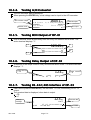
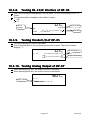
10.3.
Test Mode.................................................................................. 118
10.3.1.
Testing Control I/O Function.................................................. 118
10.3.2.
Testing Built-in RS-485 Interface........................................... 118
10.3.3.
Testing Built-in Current Loop Output ..................................... 118
10.3.4.
Testing A/D Converter........................................................... 119
10.3.5.
Testing BCD Output of OP-01 ............................................... 119
10.3.6.
Testing Relay Output of OP-02 ............................................. 119
10.3.7.
Testing RS-422/485 Interface of OP-03 ................................ 119
10.3.8.
Testing RS-232C Interface of OP-04..................................... 120
10.3.9.
Testing Parallel I/O of OP-05................................................. 120
10.3.10. Testing Analog Output of OP-07 ........................................... 120
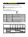
10.4.
Initializing Parameters ............................................................... 121
10.5.
Remote Operation...................................................................... 123
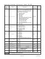
11.
Function List .................................................................................. 124
11.1.1.
Operation Keys...................................................................... 124
Page 3
11.1.2.
Outline of the Function List.................................................... 125
11.2.
Referring Parameters ................................................................ 126
11.3.
Parameter List ........................................................................... 127
12.
12.1.
12.2.
Specifications................................................................................. 154
Dimensions................................................................................ 157
Accessories ............................................................................... 157
13.
Index.............................................................................................. 158
Page 4
1. Compliance
1.1.1.
Compliance with FC
FCC
C rules
Please note that this equipment generates, uses and can radiate radio frequency
energy. This equipment has been tested and has been found to comply with the limits
of a Class A computing device pursuant to Subpart J of Part 15 of FCC rules. These
rules are designed to provide reasonable protection against interference when this
equipment is operated in a commercial environment. If this unit is operated in a
residential area it may cause some interference and under these circumstances the
user would be required to take, at his own expense, whatever measures are
necessary to eliminate the interference.
(FCC = Federal Communications Commission in the U.S.A.)
1.1.2.
Compliance with European Directives
Directives
This appliance complies with the statutory EMC (Electromagnetic Compatibility)
directive 89/336/EEC and the Low Voltage Directive 73/23/EEC for safety of electrical
equipment designed for certain voltages.
Note: The displayed value may be adversely affected under extreme electromagnetic
influences.
Page 5
2. Outline and Features
Features
The AD-4404 indicator is designed for checking and/or selecting the weight of
products carried on conveyors. The indicator has five weighing modes and a
selection function to classify 5 levels of weight. As a check weighing example, there is
a check weighing application, using a foreign matter detector.
Large display
The indicator has a blue vacuum fluorescent display (VFD).
The character height of the main display is 18 mm.
Current weighing data, names, setpoints (comparison references) and total data are
displayed at the same time.
Water-resistant panel
The classification code of the front panel is equivalent to IP-65 of IEC 529 using the
accessory rubber packing. The "IP-65" code is explained as follows:
IP:
International Protection.
6:
Against ingress of solid foreign objects.
Dust-tight. No ingress of dust.
5:
Against ingress of water with harmful effects.
Protected against water jets (no powerful jets). Water projected in jets against
the enclosure from any direction shall have no harmful effects.
Operation guidance
Messages that assist current operation are displayed on the front panel and major
operators should be able to operate the indicator without referring to the instruction
manual.
Full weighing sequences
The following five modes are installed in the AD-4404;
Automatic mode, conveyor stop mode, OK mode, manual mode and simple mode.
The five levels to select or check weight can be used for the check weighing.
AD-4404 can be linked to a foreign matter detector.
External buzzer has different sounds adapted to the result.
RS-485 interface
32 indicators can be connected to a programmable controller or a personal computer.
The protocols are according to public formats.
Optional accessories
Interface options:
AC 250 V direct drive relay, serial interface,
parallel interface, analog output, etc.
Further options for communication: CC-Link, DeviceNet and PROFIBUS.
There are three expansion slots for options.
Page 6
Check mode during operation
The monitor mode can confirm system status during operation.
The test mode can test the Input / Output interface.
Even if there is no monitor instrument, the interface can be confirmed.
2.1. Precautions
Precautions
Before use, confirm the following articles for safe operation.
Grounding the indicator
Ground the indicator. The earth terminal is on the rear panel.
Separate this earth ground line from others, like ground line of a motor, inverter or a
power source. Unless the indicator is grounded, it may result in receiving an electric
shock, cause operation error or catch fire.
Use an adequate power cord
Confirm the AC voltage, current of the power cord and the receptacle type. If the
voltage range of the cord is lower than the power line voltage, it may cause leakage or
catching fire. Use compression terminals to connect the power cord to the rear panel
terminals.
Fuse
The fuse is installed to help prevent the indicator from catching fire.
The indicator is equipped with many safety circuits. Therefore, the fuse is not damaged
in normal operation. If the fuse is damaged, do not replace it, contact your local A&D
dealer. This trouble may have been caused by strong electric discharge.
Splashing water
The indicator is not water-resistant. When the indicator is mounted to a panel with the
accessory rubber seal, the front panel is equivalent to IP-65.
Flammable gas
Do not install the indicator where flammable gas is present.
Heat radiation of the indicator
Space out instruments to radiate heat sufficiently.
Use a cooling fan to keep the operating temperature of the indicator within
specifications.
Removing the cover
Disconnect the indicator from the power source before removing the cover to avoid
receiving an electric shock.
Do not touch the internal circuit within 10 seconds after turning off the indicator to
avoid receiving an electric shock.
Page 7
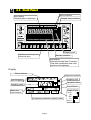
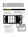
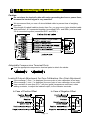
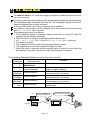
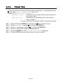
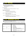
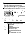
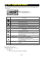
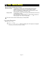
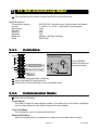
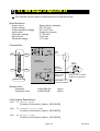
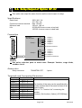
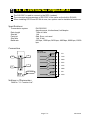
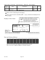
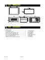
2.2. Front Panel
Status indicator
Main display
Weighing data is displayed.
Graphic status indicator
Weighing unit
Alphanumerical keys and
numerical keys
Standby indicator
Sub-display
Selected principal data. Example:
Total data, parameters and code,
guidance are displayed.
Display
Status indicator
Judgement symbol
Weighing unit
Kind of display
Operation status
Weighing value
Count Result
Name and
Code number
Comparison parameter (setpoint data)
Page 8
Graph of level
Hi Hi
Hi
OK
Lo
Lo Lo
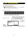
2.2.1.
Keys
The START key of the conveyor belt.
The STOP key of the conveyor belt.
The key to select a function of a key.
The key to call the code.
Pressing the CODE RECALL key to recall the code.
Pressing and holding the SHIFT key, press the CODE SET key to
select the principal codes for display in the sub-display.
The key to move the cursor or scroll the function number.
Pressing and holding the SHIFT key, press the key to decrease the
code number.
The key to select alphabetical keys, upper keys, lower keys or
numerical keys.
to
,
Alphanumeric keys.
The escape key.
The ESC key is used to undo the last key action and to return to the
previous mode.
Pressing and holding the OFF key more than three seconds in
weighing mode, turn off the display (Standby mode).
The ENTER key for parameter settings.
The ON key turns on the display while in standby mode.
Pressing and holding this key, press the key to enter the menu.
Pressing and holding the TARE key, press the ON key after turning off,
the indicator displays gross value and does not to compensate zero.
Pressing this key, the key works as the F1 key.
Pressing and holding the SHIFT key, press this key, the key works as
the F2 key. Preset the function of the F1 and F2 key at othef-2 and
othef-3 in the function list.
The key to shut off the buzzer.
Pressing and holding the SHIFT key, press the CLEAR TOTAL key to
clear the total data of the current code.
Pressing the key, this key works as the TARE key. The tare key is
used to display the net value that subtracts the tare weight from the
gross value.
Pressing and holding the SHIFT key, press the ZERO key, this key
works as the zero key. The current weighing display becomes zero and
displays sign CZ.
Page 9
2.2.2.
Symbols
Main display
Sub display
Weighing unit
While weighing sequence mode stops, weighing data is displayed.
While weighing sequence mode operates, each judged weighing
value is held and is displayed.
Code numbers, operation guidance, graph, setpoint and others are
displayed selectively.
The indicator that is displayed when the weighing unit is selected in
the calibration mode.
Status indicator
The current weighing status is displayed.
Graphic status
indicator
The current weighing situation is displayed with symbols.
The classification number is displayed, when an error occurred or
an alarm is indicated.
STABLE
The sign is illuminated when the current weighing display is stable.
GROSS
The sign is illuminated when the main display is the gross data.
NET
The sign is illuminated when the main display is the net data.
TARE ENT
Tare entered.
The sign is illuminated when a tare value stored.
HOLD
The sign is illuminated when the main display is held.
CZ
ZR.ERR
SQ.ERR
Center of zero.
The sign is illuminated when the gross value is within the center of
the zero point of zero calibration.
Zero error.
Error message for zeroing the gross data of the main display.
The sequence error sign.
Indicates a weighing sequence error.
ALARM 1
An error sign preset to alarm 1.
ALARM 2
An error sign preset to alarm 2.
Operate
The sign is illuminated while the weighing sequence works.
The sign is turned on and off while the weighing sequence is pause.
BUSY
The sign is illuminated while material is weighed and data is processed.
ZTR
Zero track function. The sign is illuminated for one second when
zero track function works.
The zero band sign.
When the gross data is within the range of the zero band (around
the zero point), this sign is illuminated.
Dynamic compensation function to correct weighing value. The sign is
illuminated when the coefficient is not 1 in the automatic mode.
0. BAND
D.COMP
Page 10
Lo
The weighing data is lighter than lower limit. Data < Lower limit.
OK
The weighing data is acceptable. Lower limit ≤ Data ≤ Higher limit
Hi
The weighing data is heavier than higher limit. Higher limit < Data
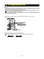
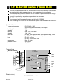
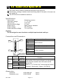
2.3. Rear Panel
Built-in RS-485 terminal.
Possible use: to read weighing data, write
parameters, connect 32 indicator units
using the multi-drop connection.
Loadcell terminal.
Eight 350Ω loadcells can be
connected in parallel.
Main
power
switch
Option
Slot 1
Option
Slot 2
Option
Slot 3
Power cord terminal
AC85V ~ 250V
Option slots to connect three
optional accessories in
maximum. Example: BCD
output, Relay output, Analog
output and field bus.
Control I/O to connect to
external control units.
11 input terminals,
11 output terminals,
An input common terminal
An output common terminal
Built-in current loop output
Use to connect A&D
external monitor or printer.
Page 11
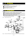
3. Installation
Installation Procedure
Remove the power cord before installing the indicator or an option.
Turn off peripheral devices before connecting them.
Insert the options before installing the indicator.
Mount the indicator to the panel.
Connect cables and wires to the indicator.
3.1. Installing Options
Caution
Remove the power cord before installing an optional accessories.
Do not install the same option to input data or comunication option using slots.
Do not assign the same function to multiple input terminals.
Never touch the internal parts within ten seconds after removing the power
cord because you may receive an electric shock.
Do not forget to tighten the screws. If a screw is not tightened, it may cause a
short circuit or an error due to noise.
Step 1 Remove the power cord.
Step 11 Initialize the RAM data in accordance with section "9.4. Initializing Parameters".
Page 12
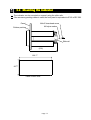
3.2. Mounting the Indicator
The indicator can be mounted on a panel using the slide rails.
If the accessory packing rubber is used, the front panel is equivalent to IP-65 of IEC 529.
Panel
M4x15 truss head screw
M4 nylon washer
Rubber packing
Slide rail
(156)
186 +1.1
-0.0
92 +0.8
-0.0
Panel Cutout Size
Page 13
3.3. Connecting the Loadcell Cable
Caution
Do not share the loadcell cable with noise-generating devices or power lines,
because the loadcell signal is very sensitive.
We recommend that you use a 6 wire shielded cable to prevent loss of weighing
precision.
If the length of loadcell cable is shorter than 5 m, you may use a 4 wire shielded cable
with terminals 1 & 2 connected together (connected EXC+ and SEN+) and terminals
3 & 4 connected together (connected EXC- and SEN-).
Adaptable Compression Terminal Parts
Use the appropriate compression terminal parts to attach the cables.
Loadcell Output Adjustment for Zero Calibration (Zero Point Adjustment)
If the message "CERR2" is displayed, the zero point of zero calibration is too large.
If the message "CERR3" is displayed, the zero point of zero calibration is too small.
Use a resistor of more than 50 kΩ with low (good) temperature coefficient, when
adding a resistor, to adjust the loadcell output, to the indicator terminals.
In Case of Positive Offset
In Case of Negative Offset
Page 14
3.3.1.
Verifying Loadcell Output and Input Sensitivity
The input sensitivity of the indicator is 0.3µV/division or more. Adapt to the following
inequality, when you design a weighing instrument using the indicator and loadcell(s).
Caution
A change in input voltage sensitivity is equivalent to a single division change
of the display. Select as large an input voltage sensitivity voltage as possible
so that the weighing interval becomes stable.
Consider the leverage if a lever is used.
E ∗B ∗D
Weighing instrument
0 .3 ≤
using one loadcell.
A
E ∗B ∗D
Weighing instrument
0 .3 ≤
using multi-loadcell
A ∗N
A: Rated capacity of loadcell [kg]
B: Rated output [mV/V]
D: Weighing interval [kg]
E: Excitation voltage [mV]
N: Number of loadcells
Verification Example
Design:
Loadcell
Rated capacity
Rated output
Excitation voltage
Weighing interval
Weighing capacity
N=1
A=750 [kg]
B=3 [mV/V]
E=5000 [mV]
D=0.05 [kg]
300 [kg]
Page 15
5000 ∗ 3 ∗ 0.05
= 1 ≥ 0.3 . Therefore,
750
regard the instrument as a good design.
3.4. Wiring the Power Cord
Caution
Ground the indicator using terminal E to avoid receiving an electric shock or
an error due to discharge of static electricity.
Do not share the ground wire with an electrical device that generates noise.
Do not use an unstable power source.
Do not share the power cord with a motor system (a noise-generating device)
to avoid operation error.
The power source can be from AC 85V to AC 250V with 50 Hz or 60 Hz.
Adaptable Compression Terminal Parts
Use the appropriate compression terminal parts to attach the cables.
Page 16
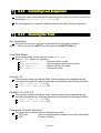
4. Basic Operation
4.1. Key Operation Examples
This section describes how to use key operation.
Caution The key operation immediately affects to the status of the indicator. Always
check the keys to select before proceeding.
4.1.1.
OFF
ON
4.1.2.
Standby Mode
Press and hold the OFF key about three seconds in the
weighing mode. Then the indicator enters the standby mode
and displays the standby indicator.
In the standby mode, All interface circuits are turned off and
only the internal circuits work.
The ON key is used to turn on the indicator.
Cursor Operation
There is a cursor on a segment (an item) that is turned on and off.
The key is used to move the cursor forward.
SHIFT +
Press and hold the SHIFT key and press the key to move the
cursor backward.
ENTER
The ENTER key is used to enter the selected item.
ESC
The ESC key is used to return to the previous mode and to
undo the last key operation.
4.1.3.
Inputting Characters
A character can be input in a current segment (an item) in the appropriate mode.
A/a
The A/a key is used to change numerical key, upper keys, lower
keys and alphabetical key..
Alphanumerical The alphanumerical keys and the ENTER key are used to
enter the parameters and to select a code number directly.
ENTER
The ENTER key is used to specify the alphanumerical data.
ESC
The ESC key is used to undo the last key operation and to
return to the previous mode.
Page 17
4.1.4.
Calling a Code
Step 1 Press the CODE RECALL key in either operation mode or normal stop mode.
Step 2 Set the code number with the following keys:
The key is used to increase the code number.
Press and hold the SHIFT key and press the key to decrease
SHIFT +
the code number.
Numerical
The numerical keys and the ENTER key is used to select a
code number directly and to enter the parameters.
ENTER
The ENTER key is used to specify the number.
ESC
The ESC key is used to undo the last key and to return to the
previous mode.
4.1.5.
Entering a Correction Mode
Step 1 Press and hold the SHIFT key and press the CODE RECALL key in the operation
mode or normal stop mode.
Step 2 Select the code number using the following keys:
, SHIFT + , Numerical, ENTER, ESC keys
Step 3 Edit some items of the code using the numerical and ENTER keys.
Step 4 Press the ESC key to return to the previous mode.
4.1.6.
Entering The Menu
Step 1 Press and hold the ENTER key and press the key in either operation mode or
normal stop mode.
Then the first layer of the menu is displayed.
Step 2 Use the following keys in the menu :
, SHIFT, Alphanumerical, A/a , ENTER, ESC keys
Step 3 Press the ESC key several times to return to normal stop mode.
Page 18
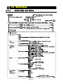
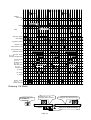
4.2. Status Chart
4.2.1.
Mode Map and Menu
Page 19
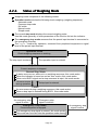
4.2.2.
Status of Weighing Mode
Weighing mode comprises of the following modes.
Operation mode includes the following check weighing (weighing sequence).
Automatic mode
Conveyor stop mode
OK mode
Manual mode
Simple mode
The normal stop mode displays the current weighing value.
Use this mode generally to enter parameters of the function list into the indicator.
The emergency stop mode assumes that the preset input terminal is connected to
the emergency stop key.
The "Input" means key operation, command from peripheral equipment or signal
level of the preset input terminal.
Operation Mode
Check weighing sequence is working.
The stop input is entered.
The operation input is entered.
Stop Mode
Current sequence is stopped.
Normal Stop Mode
A status error occurs, while not in a weighing sequence, this mode works.
When the indicator is turned on and an error occurs, this mode works.
When not a BUSY signal and a stop command is input, this mode works.
An error occurs
during operation.
A stop input is entered.
Pause
An error occurs during a weighing sequence, this mode works.
When a stop input is entered during BUSY, this mode works.
An emergency stop
signal is active.
Emergency stop
signal is inactive.
Emergency Stop Mode
Current sequence is stopped.
If an emergency stop signal is entered, this mode works.
This mode can not enter into the operation mode directly.
Page 20
An emergency stop
signal is active.
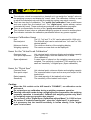
5. Calibration
The indicator, which is connected to a loadcell unit, can weigh the "weight" value on
the weighing conveyor and display its "mass" value. The calibration function is used
to adjust the displayed value so that the weighing system can weigh correctly.
There are two ways of calibration. The "actual load calibration" uses a rated mass
and zero output from the loadcell unit. The "digital span" inputs arbitrary values
(calculated by hand). These methods are selected in the calibration procedure.
There is a compensation function of the "gravity acceleration correction".
This function is used, when a calibrated weighing system is moved to another place.
The indicator maintains the calibration parameters without any power supplied.
Common Calibration Items
Unit
Decimal point
Minimum division
Weighing capacity
The "g", "kg" and "t" or "lb" can be selected (lb: USA only).
The decimal point can be selected from "not used" to "four
decimal places".
The minimum division of the weighing display.
The maximum mass that can be displayed.
Items for the "Actual Load Calibration"
Common items
Zero point adjustment
Span adjustment
Items for "Digital Span"
Common items
Zero point output
Rated capacity
Sensitivity
Unit, decimal point, minimum division and weighing capacity
A zero point output, from the loadcell unit, is used.
(Zero calibration)
A rated mass is placed on the weighing conveyor and is
weighed. The sensitivity is adjusted. This sensitivity is the
same as "sensitivity" of digital span. (Span calibration)
Unit, decimal point, minimum division and weighing capacity
The numerical data is input as the zero point output of the
loadcell unit.
The rated capacity of the loadcell unit is input.
The sensitivity of the loadcell unit is input.
Caution
When the CAL switch on the A/D board is "DISABLE", no calibration can be
performed.
Do not perform any calibration during a weighing sequence operation.
Entering calibration mode during a weighing sequence operation, the weighing
sequence operation is terminated. Calibrate the weighing system only when
the weighing sequence operation has stopped
The accuracy of the "Digital Span (Calibration without Mass)" is 1/1000 or less.
Do not use a "loadcell summing box", when the "digital span" is performed.
It is necessary that the loadcell sensitivity is known exactly, if the "digital
span" is to be used.
Page 21
5.1. Actual Load Calibration (using a Mass)
ESC key
ENTER key
If you want to return to the weighing mode during the
calibration mode, press the ESC key anytime. It is
effective until the last displayed parameter.
Example: zero adjustment only, etc.
When the key is pressed, the procedure stores the
current parameter and proceeds to the next step.
Common Calibration Items
Step 1 Press and hold the ENTER key and press the
menu in the normal stop mode.
Step 2 Press the key to select the menu CAL.
key to display the
Press the ENTER key to enter the calibration mode.
Step 3 Press the ENTER key to enter the menu CAL.
Step 4 Select a weighing unit using the numerical keys and press the
ENTER key to store it.
Step 5 Select a decimal point using the numerical keys and press the
ENTER key to store it.
Step 6 Select a minimum division using the numerical keys and press the
ENTER key to store it.
Step 7 Select a weighing capacity using the numerical keys and press
the ENTER key to store it.
Step 8 If the F1 key is pressed, it will branch out to the digital span.
Items for the "Actual Load Calibration"
Step 9 The Zero Point Adjustment
Place nothing on the weighing conveyor and press the ENTER key to
store the zero point after the STABLE indicator is displayed.
Whether the STABLE indicator is displayed or not, if you want to
store it, wait for ten seconds and press the ENTER key.
Step 10 Specify a total mass value to place on the weighing conveyor
using the numerical keys and press the ENTER key to store it.
Step 11 The Span Adjustment
Place the specified mass on the weighing conveyor and press the
ENTER key to store it after the STABLE indicator is displayed.
Whether the STABLE indicator is displayed or not, if you need to
store it, wait for ten seconds and press the ENTER key.
Step 12 Press the ESC key to return to the normal stop mode.
Page 22
5.2. Digital Span (Calibration without a Mass)
ESC key
ENTER key
If you want to return to the normal stop mode during the
calibration mode, press the ESC key anytime. It is
effective until the last displayed parameter.
Example: zero adjustment only, etc.
When the key is pressed, the procedure stores the
current parameter and proceeds to the next step.
Common Calibration Items
Step 1 Press and hold the ENTER key and press the key to display the
menu in the normal stop mode.
Step 2 Press the key twice to select the menu CAL.
Press the ENTER key to enter the calibration mode.
Step 3 Press the ENTER key to enter the menu CAL.
Step 4 Select a unit using the numerical keys and press the ENTER key
to store it.
Step 5 Select a decimal point using the numerical keys and press the
ENTER key to store it.
Step 6 Select a minimum division using the numerical keys and press the
ENTER key to store it.
Step 7 Select a weighing capcity using the numerical keys and press the
ENTER key to store it.
Step 8 Press the F1 key to proceed to the next step.
Items for "Digital Span"
Step 9 The Zero Point Adjustment
If the zero point value needs adjustment, input it using the
numerical keys and press the ENTER key to store it.
If the zero point value does not need adjustment, press the
ENTER key to proceed the next step.
Step 10 The Span Adjustment
Input the rated capacity of the loadcell unit using the numerical
keys and press the ENTER key to store it.
Step 11 Input the sensitivity of the loadcell unit in the unit of mV/V using
the numerical keys and press the ENTER key to store it.
Step 12 Press the ESC key to return the normal stop mode.
Suggestion
The digital span can be used for trimming of the actual load calibration using a mass.
Page 23
5.3. Gravity Acceleration Correction
The function compensates for weighing error due to the difference of gravity
acceleration.
G1
The place where the weighing system is calibrated.
G2
The place where the weighing system is used.
ESC key
ENTER key
If you want to return to the normal stop mode during the
calibration mode, press the ESC key anytime.
When the key is pressed, the procedure stores a current
parameter and proceeds to next step.
Step 1 Press and hold the ENTER key and press the key to display the menu in the
normal stop mode.
Step 2 Press the key to select the menu CAL. Press the ENTER key to enter the
calibration mode.
Step 3 Select the menu G with the key. Press the ENTER key to enter it.
Step 4 Input the gravity acceleration at G1 using the numerical keys and press the
ENTER key to store it.
Step 4 Input the gravity acceleration at G2 using the numerical keys and press the
ENTER key to store it.
Step 5 Press the ESC key to return the normal stop mode.
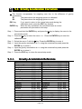
5.3.1.
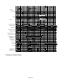
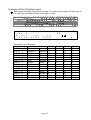
Gravity Acceleration Reference
Amsterdam
Athens
Auckland NZ
Bangkok
Birmingham
Brussels
Buenos Aires
Calcutta
Chicago
Copenhagen
Cyprus
Djakarta
Frankfurt
Glasgow
Havana
Helsinki
Kuwait
Lisbon
London (Greenwich)
Los Angeles
Madrid
9.813
9.800
9.799
9.783
9.813
9.811
9.797
9.788
9.803
9.815
9.797
9.781
9.810
9.816
9.788
9.819
9.793
9.801
9.812
9.796
9.800
m/s2
m/s2
m/s2
m/s2
m/s2
m/s2
m/s2
m/s2
m/s2
m/s2
m/s2
m/s2
m/s2
m/s2
m/s2
m/s2
m/s2
m/s2
m/s2
m/s2
m/s2
Manila
Melbourne
Mexico City
Milan
New York
Oslo
Ottawa
Paris
Rio de Janeiro
Rome
San Francisco
Singapore
Stockholm
Sydney
Tainan
Taipei
Tokyo
Vancouver, BC
Washington, DC
Wellington, NZ
Zurich
Page 24
9.784
9.800
9.779
9.806
9.802
9.819
9.806
9.809
9.788
9.803
9.800
9.781
9.818
9.797
9.788
9.790
9.798
9.809
9.801
9.803
9.807
m/s2
m/s2
m/s2
m/s2
m/s2
m/s2
m/s2
m/s2
m/s2
m/s2
m/s2
m/s2
m/s2
m/s2
m/s2
m/s2
m/s2
m/s2
m/s2
m/s2
m/s2
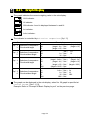
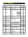
5.4. Calibration
Calibration Error
Error Code Error Status and Solution
CERR1
Resolution (Weighing capacity / minimum division) exceeds the limitation.
Increase minimum division or decrease weighing capacity.
CERR2
The initial load (no load output) is larger than 2mV/V.
Check the weighing conveyor, loadcell unit and cable.
CERR3
Negative loadcell output value.
Check the weighing conveyor, loadcell unit and cable.
CERR4
Mass value exceeds the weighing capacity.
Use a mass within the weighing capacity. (Decrease mass value)
CERR5
Mass value is too light for the calibration.
Increase mass value.
CERR6
The loadcell output to be equivalent to the minimum division is too small.
Use a greater minimum division.
CERR7
The polarity of the loadcell output is reversed.
Check the loadcell cable.
CERR8
The mass value of the weighing capacity exceeds 3.2 mV/V.
Confirm the mass and weighing capacity.
CERR9
Gravity acceleration is out of range.
Correct the value within the range of 9.770 ~ 9.835 m/s2.
CERR10 Zero output of the loadcell unit is out of range.
Trim the zero output within 0.0 ~ 2.0 mV/V.
CERR11 The loadcell output to be equivalent to minimum division is out of range.
Trim the output within 0.0 ~ 3.2 mV/V.
Page 25
[Blank page]
Page 26
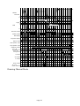
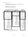
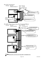
6. Check Weighing Sequence
6.1. Automatic Mode ( weighing in motion)
The mode weighs and classifies (judges or checks) the weight of an article, when it
passes it on the weighing conveyor. The article does not stop on the weighing conveyor.
Refer to "6.5. Judgement and Selector Action" for the selector action.
When gross value is within the zero band at judgement, it is ignored as a weighing
error, like touching the sensor or conveyor.
The mode can be used with foreign matter detection.
Concerning Principal Items (Including Parameter Example)
Address
Parameter
5q f-01
1
5q f-02
1
5q f-29
1
5q f-05
11011111
5q f-21
00000110
5q f-22
11011111
Address name
Parameter name
Weighing mode
Automatic mode
Selection of comparison
3 levels with target
Detector
Top edge
5q f-42
Chattering timer
5q f-43
5q f-44
5q f-45
0.00
5q f-46
5q f-52
Buzzer condition 1
Description
Setpoints and comparison method
Target, Lo (light), Hi(heavy)
Detection method
Position sensor detects the front of an article.
Buzzer sounds without OK.
1: buzzer sounds, 0: no buzzer
Conveyor stop condition
Conveyor stops for foreign matter or crush.
Selector 1 condition
Article is separated by selector 1 without OK.
The time to ignored position sensor.
Range is 0.00 to 99.99 sec.
The time between detecting an article and
Eval delay timer
averaging it. Range is 0.00 to 99.99 sec.
Time to average the weighing value.
Average timer
Range is 0.00 to 99.99 sec.
Output pulse is turned on until next article
Compare Output timer
detection. Range is 0.00 to 99.99 sec.
Delay time of selector 1 after judgement.
Selection out 1 delay timer
Range is 0.00 to 99.99 sec.
The output time of selector 1.
Select output 1 timer
Range is 0.00 to 99.99 sec.
Detection of position
sensor or zero band.
In-motion weighing
Selector is only passed OK
OK
Selector 1
Leading conveyor
Forwarding conveyor
Weighing conveyor
Loadcell
Position sensor
Page 27
Light
Gross
Zero band
0
Hi (Upper limit)
Target
Lo (Lower limit)
Net
0
Zero band, Output
Main display
Comparison display
Setpoint, Input
Start operation, Input
Stop operation, Input
OPERATE, Output
Conveyor, Output
Position sensor
5q f-42
Chattering timer
5q f-43
Eval delay timer
5q f-44
Average timer
Judgement
Judgement
Front edge
detection
Front edge
detection
Hi, Output
OK, Output
Judgement
Front edge
detection
Hi
OK
Lo, Output
5q f-46
Selection out 1 delay timer
5q f-52
Select output 1 timer
5q f-41
Buzzer ON timer
Lo
Hi
BUSY, Output
Drawing: Automatic Mode
Page 28
Lo
6.2. Conveyor Stop Mode
The conveyor stop mode is the function that the article is stopped on the weighing
conveyor for accurate measurement.
When the gross value is within zero band, the weighing value is not judged.
The mode can be used with foreign matter detection.
Caution
Set parameter of Tail Edge to place the article on the weighing conveyor
correctly.
[Function] - [Set Function] - [Sequence] -[Control] - [Tail Edge]
[5q f-29] [2]
Concerning Principal Items (Including Parameter Example)
Address
Parameter
5q f- 1
2
5q f- 2
1
5q f-29
2
5q f- 5
11011111
5q f-21
00000110
5q f-22
11011111
Address name
Parameter name
Weighing mode
Conveyor stop mode
Selection of comparison
3 levels with target
Detector
Tail edge
5q f-42
Chattering timer
5q f-43
5q f-44
5q f-45
0.00
5q f-46
5q f-52
Buzzer condition 1
Description
Setpoints and comparison method
Target, Lo (light), Hi(heavy)
Detection method
Position sensor detects the end of an article.
Buzzer sounds without OK.
1: buzzer sounds, 0: no buzzer
Conveyor stop condition
Conveyor stops for foreign matter or crush.
Selector 1 condition
Article is separated by selector 1 without OK.
The time to ignore the position sensor.
Range is 0.00 to 99.99 sec.
The time between detecting an article and
Eval delay timer
averaging it. Range is 0.00 to 99.99 sec.
Time to average the weighing value.
Average timer
Range is 0.00 to 99.99 sec.
Output pulse is turned on until next article
Compare Output timer
detection. Range is 0.00 to 99.99 sec.
Delay time of selector 6 after judgement.
Selection out 1 delay timer
Range is 0.00 to 99.99 sec.
The output time of selector 1.
Select output 1 timer
Range is 0.00 to 99.99 sec.
The end of the
article is detected
The article is stopped and
weight is judged.
Selector only passes OK
OK
Selector 1
Leading conveyor
Forwarding conveyor
Weighing conveyor
Loadcell
Position sensor
Page 29
To light
Gross
Zero band
0
Hi (Upper limit)
Target
Lo (Lower limit)
Net
0
Zero band, Output
Main display
Comparison display
Setpoint, Input
Start operation, Input
Stop operation, Input
Conveyor is stopped.
OPERATE, Output
Conveyor, Output
Position sensor
5q f-42
Chattering timer
5q f-43
Eval delay timer
5q f-44
Average timer
Judgement
Judgement
Tail detection
Tail detection
Tail detection
Hi
Hi, Output
OK, Output
Judgement
OK
Lo
Lo, Output
5q f-46
Selection out 1 delay timer
5q f-52
Select output 1 timer
5q f-41
Buzzer ON timer
Hi
BUSY, Output
Drawing: Conveyor Stop Mode
Page 30
Lo
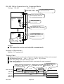
6.3. Foreign Matter Detection
The foreign matter detection is the function to reject an article including foreign matter.
The system consists of the AD-4404 and the foreign matter detector.
The rejection is performed with the following procedure.
1 When an article including foreign matter is detected, a signal is transmitted from the
foreign matter detector to a preset I/O control interface terminal of the AD-4404.
2 When the AD-4404 receives the signal, the Foreign detect timer [5q f-58]
starts.
3 When the timer is up, the current weighing value is ignored. Judgement is regarded
as fault. Rejection signal is transmitted from the AD-4404 to the selector.
4 The article is rejected with the selector.
The function can be used with automatic mode and conveyor stop mode.
Detecting foreign matter, Signal
is transmitted to AD-4404
Foreign matter detector
Time that the article reaches
to weighing conveyor.
Foreign detect timer
5q f-58
Weighing value is ignored and it is
judged as including foreign matter.
Selector 1
Leading conveyor
Weighing conveyor
Position sensor
Forwarding conveyor
To foreign matter
Loadcell
To preset terminal of I/O interface of AD-4404
Concerning Principal Items (Including Parameter Example)
Address
Address name
Parameter
Parameter name
IN
10(A10)
function
1n f-10
Foreign matter detection
9
Description
Terminal A10 of the I/O interface is used as
detection input.
Delay time that the article moves from the
detector to the weighing conveyor.
Range is 0.00 to 99.99 sec.
5q f-58
Foreign detect timer
5q f- 1
1 or 2
Weighing mode
Automatic mode or Conveyor stop mode
Refer to Automatic mode or Conveyor stop mode for other items
Page 31
Gross
Zero band
0
Hi (Upper limit)
Target
Lo (Lower limit)
Net
0
Zero band, Output
Main display
Comparison display
Setpoint, Input
Start operation, Input
Stop operation, Input
OPERATE, Output
Conveyor, Output
Position sensor
5q f-42
Chattering timer
5q f-43
Eval delay timer
5q f-44
Average timer
Judgement
Judgement
Judgement
Front edge
detection
Front edge
detection
Front edge
detection
Hi, Output
OK, Output
Lo, Output
Selection out 1 delay timer
5q f-46
Select output 1 timer
5q f-52
Selector 1, Output
5q f-41
Buzzer ON timer
OK
When foreign matter is detected,
it is input to AD-4404
Delay time that article moves
to weighing conveyor.
BUSY, Output
Foreign matter detection, Input
Foreign detect timer
Foreign material detection
Drawing: Foreign Matter Detection
Page 32
It is regarded as
including foreign matter.
OK
6.4. OK Mode
The procedure of OK mode is as follows:
1 Put the article on the stopped weighing conveyor.
2 Pack the elements into the article by hand.
3 Press the START key. When the weighing value is OK, the article can be moved out.
The mode can be used with the buzzer according to the preset parameters.
In the stop mode, the current weighing value and the comparison display is always
updated. The comparison output is turned off. The buzzer and the comparison display
are turned off when the weighing value is within the zero band.
In the beginning of the operation mode, the display is reset and the buzzer becomes silent.
When Eval delay timer [5qf-43] is up, averaging and judgement is performed.
When the result is OK, the preset OK terminal is turned on.
When judgement is achieved, the weighing value and the comparison result are held,
the conveyor output is turned on and the article is moved out.
When Conveyor stop delay timer [5qf-59] is up, the hold display is canceled,
comparison output and conveyor output are turned off.
When the result is not OK, the comparison is achieved and the display is held until
Conveyor stop delay timer [5qf-59] is up.
The mode does not use any selector.
Caution
The buzzer is used for hand operation support with the following AND condition.
1 While stopping conveyor.
2 Gross value is not within zero band.
5qf5qf3 Buzzer condition 1 [5qf
5qf-5] to Buzzer condition 6 [5qf
5qf-10]
10 are
already preset.
Concerning Principal Items (Including Parameter Example)
Address
Parameter
5q f- 1
3
5q f- 2
1
5q f-29
2
5q f- 6
01000000
5q f- 8
00100000
5q f-10
00010000
5q f-41
500
Address name
Parameter name
Weighing mode
OK mode
Selection of comparison
3 levels with target
Detector
Tail edge
5q f-59
Conveyor stop delay timer
Buzzer condition 2
Buzzer condition 4
Buzzer condition 6
Buzzer ON timer
Description
Setpoints and comparison method
Target, Lo (light), Hi(heavy)
Detection method
Position sensor detects the end of an article.
Buzzer sounds at Lo. Interval is 0.5Hz.
1: buzzer sounds, 0: no buzzer
Buzzer sounds at OK. Interval is 2Hz.
1: buzzer sounds, 0: no buzzer
Buzzer sounds at Hi. Interval is 8Hz.
1: buzzer sounds, 0: no buzzer
Range is 0.00 to 99.99 sec.
5.00 seconds
The delay timer of conveyor after judgement.
Range is 0.00 to 99.99 sec.
Page 33
Gross
Zero band
0
Hi (Upper limit)
Target
Lo (Lower limit)
Net
0
Zero band, Output
Main display
Comparison display
Setpoint, Input
Start operation, Input
Stop operation, Input
OPERATE, Output
Conveyor, Output
5q f-59
Conveyor stop delay timer
Position sensor
5q f-42
Chattering timer
5q f-43
Eval delay timer
5q f-44
Average timer
Tail detection
Judgement
Judgement
Hi, Output
OK, Output
Tail detection
Judgement
Hi
OK
OK
Lo, Output
Buzzer , Output
5q f-41
Buzzer ON timer
Drawing: OK Mode
Pack them and press
the START key.
If weight is Lo or Hi,
conveyor does not move.
If weight is OK, conveyor moves.
Forwarding conveyor
Weighing conveyor
The passed article is detected.
Loadcell
Position sensor
Page 34
6.5. Manual Mode
The manual mode is the mode that weighs the article by hand operation and does
not use a conveyor.
In the stop mode, the current weighing value and comparison display are always updated.
The comparison output and buzzer are turned off. The comparison display is turned off,
when the weighing value is within zero band.
In the operation mode, the current weighing value is updated.
The detection of the article uses the weighing value that crosses from the zero band
and Detector [5q f-29] is not used.
The weighing procedure is as follows:
1 The comparison display, comparison output and buzzer are turned off, when the
weighing value is within the zero band.
2 When the article is weighed, the weighing display blinks once.
3 Eval delay timer [5q f-43] and Average timer [5q f-44] are up.
4 The weight is judged.
5 The comparison result is output and the preset buzzer sounds.
6 The weighing value and the comparison display are held.
7 When the article is removed and the weighing value is within the zero band, the
hold display is canceled, comparison output and buzzer are canceled.
Concerning Principal Items (Including Parameter Example)
Address
Parameter
5q f-01
4
5q f-02
1
5q f- 6
01000000
5q f- 8
00100000
5q f-10
00010000
5q f-41
500
Address name
Parameter name
Weighing mode
Manual mode
Selection of comparison
3 levels with target
Buzzer condition 2
Buzzer condition 4
Buzzer condition 6
Buzzer ON timer
OK
Description
Setpoints and comparison method
Target, Lo (light), Hi(heavy)
Buzzer sounds at Lo. Interval is 0.5Hz.
1: buzzer sounds, 0: no buzzer
Buzzer sounds without OK. Interval is 2Hz.
1: buzzer sounds, 0: no buzzer
Buzzer sounds at Hi. Interval is 8Hz.
1: buzzer sounds, 0: no buzzer
Range is 0.00 to 99.99 sec.
5.00 seconds
Press the START key
and place the article.
The result can be indicated
AD-4404
Loadcell
Page 35
Gross
Zero band
0
Hi (Upper limit)
Target
Lo (Lower limit)
Net
0
Zero band, Output
Stability, Output
Main display
Comparison display
Setpoint, Input
Start operation, Input
Stop operation, Input
OPERATE, Output
5q f-43
Eval delay timer
5q f-44
Average timer
Judgement
Judgement
Hi
Hi, Output
OK
OK, Output
Lo, Output
BUSY, Output
5q f-41
Buzzer ON timer
Drawing: Manual Mode
Page 36
6.6. Simple Mode
The simple mode is used to compare the weighing value and the setpoints.
Setpoints, means preset value to be used comparison, are used for buzzer,
comparison display and output. There are five setpoints of LoLo, Lo, OK, Hi, HiHi.
The current weighing value and the comparison display are always updated. The
comparison display, the comparison output and buzzer are turned off, when the
weighing value is within the zero band.
Accumulation, is achieved at judgement, ignores stop mode and operation mode, and
is not achieved at pause.
Concerning Principal Items (Including Parameter Example)
Address
Parameter
5q f-01
5
5q f-02
1
5q f- 5
11011111
Address name
Parameter name
Weighing mode
Simple mode
Selection of comparison
3 levels with target
Buzzer condition 1
OK
Description
Setpoints and comparison method
Target, Lo (light), Hi(heavy)
Buzzer sounds without OK.
1: buzzer sounds, 0: no buzzer
Current weight can be checked
with light and buzzer.
AD-4404
Loadcell
Page 37
Gross
Zero band
0
Hi (Upper limit)
Target
Lo (Lower limit)
Net
0
Zero band, Output
Stability, Output
Main display
Comparison display
Setpoint, Input
Start operation, Input
Stop operation, Input
OPERATE, Output
5q f-43
Eval delay timer
5q f-44
Average timer
Judgement
Hi, Output
OK, Output
Lo, Output
BUSY, Output
5q f-41
Buzzer ON timer
Drawing: Simple Mode
Page 38
6.7. Status and Check Weighing Sequence
The status of the indicator, the display and each interface are according to the status
of the check weighing sequence.
Preset a parameter for each terminal function in the menu ControlI/O.
[1n f- 1] to [1n f- 11]
Function] - [Set Function] - [Control I/O] - [Input]
[0utf- 1] to [0ut f- 11] Function] - [Set Function] - [Control I/O] - [Output]
Principal Status List
Location and function name.................... Control output or output terminal
Conveyor (14)
In normal stop mode ............................ Conveyor is stopped.
In operation mode
For automatic mode, conveyor
stop mode, OK mode................. It is moving.
For manual mode and simple
mode ........................................... It is stopped.
In pause ................................................ It is stopped.
Location and function name.................... Status indicator
OPERATE
In normal stop mode ............................ It turns off.
In operation mode ................................ It turns on.
In pause ................................................ It blinks.
Location and function name.................... Status indicator and Control output
Hi, OK, Lo (Comparison result)
In normal stop mode
For automatic mode, conveyor
stop mode ................................... It turns off.
For manual mode, OK mode,
simple mode ............................... It displays result for the current weight.
In operation mode
For automatic mode, conveyor
stop mode ................................... It displays result.
For manual mode, OK mode............ It turns off before judgement.
It displays result after judgement.
For simple mode ............................... It displays result for the current weight.
In pause ................................................ It displays result.
Location and function name.................... Status indicator
ZTR (Zero tracking)
In normal stop mode ............................ It displays for one second, when static zero tracking
is achieved.
In operation mode ................................ It displays for one second, when static or dynamic
zero tracking is achieved
In pause ................................................ It displays for one second, when static zero tracking
is achieved.
Page 39
Location and function name.................... Status indicator
0.BAND (Zero band)
In normal stop mode, operation
It displays judgement whether the weighing value is
mode, pause............................... within zero band.
Location and function name.................... Status indicator
D.COMP (Dynamic compensation)
In normal stop mode ............................ It turns off.
In operation mode ................................ It displays, when coefficient is not 1.
In pause ................................................ It is turned off.
Location and function name.................... Weighing value
In normal stop mode ............................ It displays gross or net.
In operation mode ................................ It displays, when coefficient is not 1.
For automatic mode, conveyor
stop mode ................................... It displays and holds net of result.
For manual mode.............................. Net is displayed before judgement.
It displays result after judgement.
For OK mode..................................... It turns off before judgement.
It displays result after judgement.
For simple mode ............................... Gross or net is displayed.
In pause ................................................ Gross or net is displayed.
Location and function name.................... Upper side of graphic status indicator
In normal stop mode
For automatic mode, conveyor
stop mode ................................... It is turned off.
For manual mode, OK mode,
simple mode ............................... It displays result for the current weight.
In operation mode
For automatic mode, conveyor
stop mode ................................... It displays result.
For manual mode, OK mode............ It turns off before judgement.
It displays result after judgement.
For simple mode ............................... It displays result for the current weight.
In pause ................................................ It displays result.
In case of sequence error................. Error number is displayed
Location and function name.................... Under side of graphic status indicator
In normal stop mode ............................ It is not used.
In operation mode
For automatic mode, conveyor
stop mode, OK mode................. It displays status of conveyor and weighing sequence.
For manual mode, simple mode ...... It is not used.
In pause ................................................ It is not used. O is displayed, when Force target
finish [othf-3] [7] is set to the F1 or F2 key.
Location and function name.................... Weighing unit indicator
In normal stop mode, operation
mode, pause............................... Unit is displayed.
Page 40
Location and function name....................
In normal stop mode ............................
In operation mode
For automatic mode, conveyor
stop mode ...................................
For manual mode, OK mode............
Graph indicator of sub-display
Graph of net is displayed.
It displays and holds graph of result
It turns off before judgement.
It displays result after judgement.
For simple mode ............................... It displays graph of net.
In pause ................................................ It displays graph of net. If there is error, an error
message is displayed.
Location and function name.................... Gross of sub-display
In normal stop mode, operation
mode ........................................... Gross is displayed.
In pause ................................................ Gross is displayed. If there is error, an error message
is displayed.
Location and function name.................... Net of sub-display
In normal stop mode, operation
mode ........................................... Net is displayed.
In pause ................................................ Net is displayed. If there is error, an error message is
displayed.
Location and function name.................... Buzzer
In normal stop mode
For automatic mode, conveyor
stop mode, manual mode, OK
mode ........................................... It turns off.
Simple mode in normal stop mode,
operation mode and pause........ It is according to the following parameters.
Buzzer condition 1 [5q f-5] to
Buzzer condition 6 [5q f-10] and
Buzzer on timer [5q f-41].
When pressing the key preset Buzzer stop [1n ]
[8] , it stops sound.
Location and function name.................... Comparison output (HiHi, Hi, OK, Lo, LoLo)
In normal stop mode
For automatic mode, conveyor
stop mode, manual mode, OK
mode ........................................... It turns off.
For simple mode ............................... It is output judgement of the current weight.
In operation mode
For automatic mode, conveyor
stop mode, manual mode .......... It is output judgement.
For OK mode..................................... It turns off.
For simple mode ............................... It is output judgement of the current weight.
In pause ................................................ It is output judgement.
Page 41
Location and function name.................... Selector output (HiHi, Hi, OK, Lo, LoLo)
In normal stop mode ............................ It turns off.
In operation mode
For automatic mode, conveyor
stop mode ................................... It is according to the following parameters.
Selection out 1 delay timer [5q f-46] to
Selection out 6 delay timer [5q f-51],
Select output 1 timer [5q f-52] to
Select output 6 timer [5q f-57]
For , manual mode, OK mode,
simple mode ............................... It turns off.
In pause ................................................ When entering into pause, output is held.
When returning to operation, output is continued.
Page 42
7. Code
The code is necessary to weigh the article and is commonly used in all modes.
The AD-4404 can store 100 set of codes without any power supply.
When recalling a code in this mode, the code can be used.
There are two ways to operate the code.
The way to edit principal parameters of the code in the sub-display.
The way to operate (Edit, Search, Delete, Copy, Tare) the code in menu Code Edit.
Select a backup method of code at Save data [othf-8].
If Save in flash memory [othf-8] [2] is selected, when opening menu Code
Edit, the current sequence is stopped.
[Function] - [Set function] - [General] - [Others] - [Save data]
Select a method to recall the code at Code recall method [5qf-81].
[Function] - [Set function] - [Sequence] - [Others]
Each code stores the following parameters.
These parameters can be accessed at the menu Edit of Code Edit.
Display Symbol
Item Name and Description
Code
number
** is 0 to 99.
Code **
Name
12 characters
Name
Target weight
Target
High limit
Hi
Low limit
Lo
High-high limit
HiHi
Low-Low limit
LoLo
Zero band
Zero Band
Full filling
Full
Preset Tare
PT
Target count
The number to stop the conveyor.
Tgt#
Total count
Total number that judged weighing.
Tot#
Lo ≤ weight ≤ Hi
OK count
OK#
weight ≤ Lo or Hi ≤ weight
NG count
NG#
Hi < weight ≤ HiHi or
Hi < weight
Hi count
Hi#
LoLo
≤
weight
<
Lo
or
weight < Lo
Lo count
Lo#
HiHi < weight
HiHi count
HiHi#
weight < LoLo
LoLo count
LoLo#
Foreign matter detection count
FMD#
Duplication# Duplication count
Crush count
Crush#
Maximum
Max
Minimum
Min
Average
Average
Standard deviation
σn-1
STD
Population standard deviation
σn
STDP
Total of the weighing value
Total
Page 43
7.1. Use of the Code
7.1.1.
Recalling a Code
A preset code can be recalled to use it always.
Caution
If the code number is changed during operation, the I/O status is changed,
too.
Step 1 Press the CODE RECALL key.
Step 2 Enter code number using the numerical keys. Press the ENTER key to recall it.
Then the I/O status and the display are changed.
7.1.2.
Editing a Code in the SubSub-display
The setpoints, LoLo, Lo, Target, Hi and HiHi can be edited in the sub-display always.
Refer to Selection of comparison [5q f-2] for selection of setpoint.
[Function] - [Set function] - [Sequence] - [Basic] - [Selection of comparison]
Preset sub-display form to edit setpoints.
[Function] - [Set function] - [General] - [Sub-display]
Caution
If the code number or its parameter is changed during operation, the I/O
status is changed, too.
Step 1 Press and hold the SHIFT key and press the CODE SET key.
Step 2 Enter the setpoint using the numerical keys. Press the ENTER key to store it and
proceed to the next setpoint.
Step 3 Continue step 2 until entering all setpoints.
Step 4 Press the ESC key twice to return to previous mode.
Page 44
7.2. The Menu of Code Edit
The code can operate with the following menu of Code Edit.
Edit ..................................Edits full parameters of the code.
Search .............................Finds a blank code.
Delete .............................Deletes all data or a part of the data for the code.
Total ...........................Deletes total for a code.
Setpoint & Total...Deletes setpoint and total for a code.
All Totals ..............Deletes total for all codes.
All Codes .................Deletes all codes.
Copy ..................................Copies all parameters of a code to another code.
PT (Preset tare) .................... Stores the current tare value to the preset tare of the
specified code.
7.2.1.
Edit
This menu item can edit all of the parameters of the code.
Step 1 Press and hold the ENTER key and press the key to enter the menu.
Step 2 Select Code Edit using the key. Press the ENTER key.
Step 3 Press the ENTER key to enter the menu Edit.
Step 4 Enter a code number using the numerical keys. Press the ENTER key.
Step 5 Edit each parmeter of the code using alphanumerical keys.
Press the ENTER key to enter a new parameter and proceed to the next item.
Step 6 Press the ESC key several times to return to the previous mode.
7.2.2.
Search
This menu item can find a blank code.
Step 1 Press and hold the ENTER key and press the key to enter the menu.
Step 2 Select Code Edit using the key. Press the ENTER key.
Step 3 Select Serach using the key. Press the ENTER key.
Step 4 Press the ENTER key. Then the code number of a blank code is displayed.
Step 5 Press the ESC key several times to return to previous mode.
Page 45
7.2.3.
Delete
This menu item can delete all or a part of the data for the code.
Step
Step
Step
Step
1
2
3
4
Press and hold the ENTER key and press the key to enter the menu.
Select Code Edit using the key. Press the ENTER key.
Select Delete using the key. Press the ENTER key.
Select menu using the key. Press the ENTER key.
Total ................................... Deletes total for a code.
Setpoint & Total ............ Deletes setpoint and total for a code.
All Totals ....................... Deletes total for all codes.
All Codes .......................... Deletes all codes.
In case that Total or Setpoint & Total is selected.
Step 5 Enter a code number using the numerical keys.
Press the ENTER key to delete it. Then Deleted is displayed.
In case that All Totals or All Codes is selected.
Step 6 Press the ENTER key to delete it. Then Deleted is displayed.
Step 7 Press the ESC key several times to return to previous mode.
7.2.4.
Copy
This menu item can copy all parameters of a code to another code.
Step 1 Press and hold the ENTER key and press the key to enter the menu.
Step 2 Select Code Edit using the key. Press the ENTER key.
Step 3 Select Copy using the key. Press the ENTER key.
Step 4 Enter the number of a source code using the numerical keys. Press the ENTER key.
Step 5 Enter the number of new code using the numerical keys. Press the ENTER key.
Then Copied Code# is displayed.
Step 6 Press the ESC key several times to return to previous mode.
Page 46
7.2.5.
Preset Tare
This menu item can store the current tare value to preset tare ( PT) of the specified code.
Preset the Preset tare=0 choose [genff-12].
[genf-12] Preset tare=0 choose
[1] Last tare ......... If preset tare of the recalled code is zero, the previous
tare value is used.
[2] Last tare ......... If preset tare of the recalled code is zero, the tare
value is cleared.
[Function] - [Set function] - [General] - [Basic] - [Preset tare=0 choose]
Step 1 Press and hold the ENTER key and press the key to enter the menu.
Step 2 Select Code Edit using the key. Press the ENTER key.
Step 3 Select PT (preset tare) using the key. Press the ENTER key.
Step 4 Enter the code number using the numerical keys.
Step 5 Press the ENTER key. Then Copied tare value is displayed.
Step 6 Press the ESC key several times to return to previous mode.
Page 47
7.3. Recalling a Code
The method to recall a code can be selected at Code recall method [5qf-81].
Function and parameter
5qf-81
1
5qf-81
2
5qf-81
3
Code recall method
Key/Serial I/F
Code recall method
Parallel I/F
Code recall method
External switch control
[Function] - [Set function] - [Sequence] - [Other]
Detail of Parameters
[5q f-81] Code recall method
[1] Key/Serial I/F
A code is recalled with key operation or input data of the interface.
The last data input has effect.
In case of using the Key Operation:
Press the CODE RECALL. Enter a code number and press ENTER key.
In case of using the Serial Interface:
The code number can be entered by command mode.
Built-in RS-485.
RS-422/485 interface of OP-03.
RS-232C interface of OP-04.
In Case of Field Bus Interface:
The code number is specified by PLC data.
CC-link of OP-20.
DeviceNet of OP-21.
PROFIBUS of OP-22.
[5q f-81] Code recall method
[2] Parallel I/F
A code is recalled with input data of the control I/O or parallel interface.
Use BCD code.
In Case of Parallel Interface:
The code number can be specified with BCD code. Example: encoder switch.
Control I/O.
Parallel interface of OP-05.
[5q f-81] Code recall method
[3] External switch control
Method of 1 or 2 can be selected at an input terminal specified to code
number 48 in control I/O or OP-05. Terminal status is as follows:
Off:
On:
1, Key/Serial I/F
2, Parallel I/F. Code number of 2 is kept until next input.
Page 48
Caution
When selecting Parallel I/F [2], do not specify the same function to the
control I/O and OP-05.
Example:
When selecting External switch control [3], select External switch
control [1nf-01] [48] to terminal 1.
When selecting External switch control [3],
control [05f-01] [48] to terminal 1 of OP-05.
select External switch
When reducing the number of wires for the parallel interface, connect all common
wires together and select the interface with the wires specified to External
switch control [3].
Page 49
8. Other Functions
8.1. Zero Tracking Function
The function automatically traces the weighing deviation at the center of zero and
keeps the zero display of the gross display.
Symbol
ZTR
8.1.1.
The sign is illuminated for one second when zero track function works.
Static Zero Tracking Function
The function is used during stop mode, manual mode, OK mode and simple mode.
When the weighing value displays zero, if the weighing value is within zero tracking motion
range after zero tracking time, the function resets the weighing value to zero.
The function can work with a slow deviation and does not respond to quick deviations,
such as a conveyor.
Concerning Parameters
[genf-7]
[genf-8]
Zero tracking time
0.1s interval [0-99]
Zero tracking motion
0.1d interval [0-99]
[Function] - [Set function] - [General]
Zero tracking motion
genf-8
Within the range.
To the center of zero.
Weighing value
Weighing value = 0
Status of zero tracking
ZTR
ZTR
Out of range
Zero tracking time
genf-7
Page 50
ZTR
8.1.2.
Dynamic Zero Tracking Function
The function is used during automatic mode and conveyor stop mode, also when the
conveyor is moving.
The function can be used for gross display.
To average the weighing value is performed at a constant time before loading the
article.
The function reduces one digit of an error in each zero tacking time, when the
compensation value is more than ±1.0 digit. The function does not zero the display
value all at once.
Concerning Parameters
[5q f-71]
[5q f-72]
[5q f-73]
[5q f-74]
Zero tracking back timer
0.1s interval [0-50]
Zero tracking average timer
0.1s interval [0-50]
Zero tracking MIN interval
0.1d interval [0-999]
Zero tracking amplitude
0.1d interval [0-999]
[Function] - [Set function] - [Sequence] - [Zero track]
5q f-72,
Zero tracking average timer
5q f-71, Zero tracking back timer
It is time to stop zero tacking before
weighing the article.
5q f-74,
Zero tracking amplitude
5q f-72, Zero tracking average timer
It is time to perform zero tacking.
Gross
0
Detection
Position sensor
5q f-42
Chattering timer
5q f-43
Eval delay timer
Detection
Judgement
Judgement
5q f-72
Zero tracking average timer
5q f-73
Zero tracking MIN interval
Zero tracking is calculated at this time
Page 51
5q f-73, Zero tracking MIN interval
If the article is detected within time
of 5q f-73, zero tracking is not
attained.
8.2. Judgement and Selector Action
The function is used to weigh and classify (judge or check) the article put on the weighing
conveyor in automatic mode [5q f-1] [1] and conveyor stop mode [5q f-1] [2].
The actions of the selectors can be selected at Selection of comparison [5q f- 2]
and Selector 1 condition [5q f-22] to Selector 1 condition [5q f-22].
Example: "If it includes foreign matter, push it using selector 1.". [5q f-22] [000000100].
The action of the conveyor can be selected at Conveyor stop condition [5q f-21].
Example: "If it is OK, pause conveyor and pick up it by hand". [5q f-21] [001000000].
There are five kinds of Selection comparison [5q f-2].
A maximum of six selectors can be selected.
Function and parameter
5qf-2
1
Selection of comparison
3 levels with target
5qf-2
2
Selection of comparison
3 levels without target
5qf-2
3
Selection of comparison
5 levels with target
5qf-2
4
Selection of comparison
5 levels without target
5qf-22
5qf-23
5qf-24
5qf-25
5qf-26
5qf-27
Selector 1 condition
Selector 2 condition
Selector 3 condition
Selector 4 condition
Selector 5 condition
Selector 6 condition
Description
Lo output
Net <
OK output
(target - Lo) ≤ Net ≤
Hi output
(target + Hi) < Net
Lo output
Net <
OK output
Lo ≤ Net ≤
Hi output
Hi < Net
LoLo output
Net <
Lo output
(target - LoLo) ≤ Net <
OK output
(target - Lo) ≤ Net ≤
Hi output
(target + Hi) < Net ≤
HiHi output (target + HiHi) < Net
LoLo output
Net <
Lo output
LoLo ≤ Net <
OK output
Lo ≤ Net ≤
Hi output
Hi < Net ≤
HiHi output
HiHi < Net
(target - Lo)
(target + Hi)
Lo
Hi
(target - LoLo)
(target - Lo)
(target + Hi)
(target + HiHi)
LoLo
Lo
Hi
HiHi
1: push, 0: not pushed
Example: 11011111
Each bits means as follows:
LoLo,
Lo,
OK,
Hi,
HiHi,
Foreign material detection,
Duplication,
Crush
Page 52
8.3. LossLoss-inin-weight
The function is used to weigh the decrease of the articles in a positive value.
Loss-in-weight [5q f-3] [1]
The tare value can be set from the following value.
Weighing tare and tare key operation
Preset value of the code
The tare value received by serial interface
Weighing Procedure
Step 1 Make zero display using the tare function to store all articles and tare.
Step 2 When weighing articles on the weighing conveyor, the decrease in the weight is
displayed as a positive value.
8.4. Motion Compensation
The function is used at automatic mode [5q f-1] [1] that continuously moves the
weighing conveyor.
The function stores the compensation coefficient.
Move correction coefficient [5q f-12]
The function calculates the correction weight by the following formula.
Compensation value = (compensation coefficient) x (weighing value in motion)
When the compensation coefficient is not 1.00000 in the automatic mode, indicator
D.COMP is displayed and the value is compensated.
Page 53
8.5. Detection Method
There are four detection methods for the article.
Detecting the front of the article with the position sensor.
Detecting the end of the article with the position sensor.
Detecting gross above the zero band.
Detecting gross within the zero band.
Place the position sensor at the front of the weighing conveyor.
The position sensor is assumed to be a photoelectric sensor or laser sensor
Use the Chattering timer [5q f-42] to prevent an error.
Use the Eval delay timer [5q f-43], when the article is detected.
8.5.1.
Detecting Front with Position
Position Sensor
Select Top edge of the Detector [5q f-29] [1].
Procedure:
1 The front of the article crosses to the position sensor.
2 When the sensor output changes from OFF to ON, Chattering timer [5q f-42]
starts.
3 When Chattering timer [5q f-42] is up, Eval delay timer [5q f-43] starts.
4 When Eval delay timer [5q f-43] is up, the detection has effect.
Memo
If the article is packed in a clear bag, use a long delay time to prevent an error with
Chattering timer [5q f-42].
8.5.2.
Detecting End wit
with
h Position Sensor
Select Tail edge of the Detector [5q f-29] [2].
The tolerance of Eval delay timer [5q f-43] is wide, because the timer starts
after the article is put on the weighing conveyor that moves in various velocities.
Procedure:
1 The end of the article crosses to the position sensor.
2 The sensor output changes from ON to OFF.
3 Eval delay timer [5q f-43] starts.
4 When Eval delay timer [5q f-43] is up, the detection has effect.
Page 54
8.5.3.
Detecting Gross Value above Zero Band
Select Over zero band of gross of the Detector [5q f-29] [3].
Procedure:
1 The article is moved on the weighing conveyor.
2 When the gross is above the zero band, the detection has effect.
Caution
This method can not be used for high velocity and intolerable vibration of the
weighing conveyor, because it can not detect duplication of the articles or the
position of the article.
8.5.4.
Detecting Gross Value within Zero Band
Select Zero band of gross of the Detector [5q f-29] [4].
Procedure:
1 When the gross value is within the zero band, the detection has effect.
8.6. Check to Forward the Article
The function is used to forward the compared article from the weighing conveyor.
Select OK mode of the Weighing mode [5q f-1] [3] to use the check.
Select the mode at Detector [5q f-29].
Procedure for this mode:
1 When the comparison has effect,
the article is forwarded from the weighing conveyor and
Conveyor stop delay timer [5q f-59] starts.
2 The conveyor moves, until Conveyor stop delay timer [5q f-59] is up.
Page 55
8.7. Duplication of the Articles
When the next article is placed on the weighing conveyor before the last article is
forwarded from the conveyor, an error message and SQ.ERR2 is displayed and
duplication is output.
The total of the weighing value classifies the duplication in the total data.
Caution
Trim the Chattering timer [5q f-29] and placement of the position sensor to
avoid duplication.
When the next article reaches the weighing conveyor and the last
weighing is not finished due to the short interval, an error is output.
Box
5kg
Box
5kg
Box
5kg
Leading conveyor
Selector
Box
5kg
Forwarding conveyor
Weighing conveyor
Position sensor
Loadcell
8.8. Crush of the Articles
When articles move between the weighing conveyor and the selector, an error
message and SQ.ERR6 is displayed and crush is output.
At maximum, the AD-4404 can control ten articles that are waiting for the selector.
The total of the weighing value is classified as crushed in the total data.
When the interval is short and the distance between the weighing conveyor and selector is
long and the quantity of moving articles is more than ten, an error is output.
10 boxes maximum
light
light
light
light
Selector
Forwarding conveyor
Leading conveyor
Position sensor
Weighing conveyor
Loadcell
Page 56
8.9. BUSY Output
The BUSY output is turned on at loading the article on the weighing conveyor.
The BUSY output is turned off until it classifies with the selector.
And the AD-4404 can control up to ten articles continuously.
If an article is loaded on the weighing conveyor after the busy state is off, it can avoid
duplication and crush of the articles. It is effective to have a long weighing interval.
The BUSY signal is output on the following condition.
The BUSY signal is output, when the following timer is counting.
Eval delay timer [5q f-43]
Average timer [5q f-44]
Selection out 1 delay timer [5q f-46]
Selection out 2 delay timer [5q f-47]
Selection out 3 delay timer [5q f-48]
Selection out 4 delay timer [5q f-49]
Selection out 5 delay timer [5q f-50]
Selection out 6 delay timer [5q f-51]
Select output 1 timer [5q f-52]
Select output 2 timer [5q f-53]
Select output 3 timer [5q f-54]
Select output 4 timer [5q f-55]
Select output 5 timer [5q f-56]
Select output 6 timer [5q f-57]
8.10. Stop Input during BUSY
Procedure for a stop input during operation:
1 When a stop input is entered while BUSY is turned on, the status changes to
pause.
2 All timers are held. Status indicators blink.
Procedure to continue the current weighing:
1 When an operation input is entered during pause, all timers restart counting.
Procedure for a stop input during pause:
1 When a stop input is entered during pause, status changes to stop mode.
2 All timers are reset. Status indicators are turned off.
Refer to " 4.2.2. Status of Weighing Mode".
Page 57
8.11. Output for Foreign Matter Detection
Procedure:
1 When the sensor detects foreign matter and sends the signal to the AD-4404, the
foreign matter detection is output until the AD-4404 judges the signal and totals it.
The output can be used to control peripherals.
This signal means that there is foreign matter between the sensor and the weighing
conveyor.
Procedure for a stop input during the detection:
1 When a stop input is entered during the detection, the status changes to pause.
2 All timers are held. Status indicators blink.
Refer to " 6.3. Foreign Matter Detection".
8.12. Evaluation Output
There are three types of output for judgement.
Comparison output.
Output to selectors.
Buzzer output.
8.12.1.
Comparison Output
The comparison output is used to input signals to a PLC and to a peripheral indicator.
It is output, when averaging weight and judging it.
Kind of output: LoLo, Lo, OK, Hi, HiHi, Foreign matter, Duplication, Crush, NG.
Relations: Conveyor stop condition [5q f-21], Sub-display, I/O output,
Page 58
8.12.2.
Output to Selectors
The output is used to control the selector using the timer.
A maximum of six selectors can be connected to the AD-4404.
Output according to conditions and timers.
Selector 1 condition [5q f-22]
Selector 2 condition [5q f-23]
Selector 3 condition [5q f-24]
Selector 4 condition [5q f-25]
Selector 5 condition [5q f-26]
Selector 6 condition [5q f-27]
Selector 1 condition [5q f-22]
When the interval is short and the distance between the weighing conveyor and
selector is long, a maximum of ten judgements will be stored into memory for each
selector.
Therefore each selector can be stored ten suits of judgement, the output delay timer
and output timer. At maximum, sixty suits of data can be stored in the six selectors.
Net
0
5q f-43
Eval delay timer
5q f-44
Average timer
Judgement
Judgement
5q f-46
Selection out 1 delay timer
5q f-52
Select output 1 timer
5q f-46
Selection out 1 delay timer
5q f-52
Select output 1 timer
5q f-46
Selection out 1 delay timer
5q f-52
Select output 1 timer
5q f-46
Selection out 1 delay timer
5q f-52
Select output 1 timer
Page 59
Judgement
Judgement
8.13. Buzzer Output
The judgement of the buzzer output is the same as the judgement of comparison output.
The buzzer can be select six rhythms of sound. Each buzzer condition stores conditions to
sound it for LoLo, Lo, OK, Hi, HiHi, foreign matter, duplication, crush and counter limit.
Buzzer condition 1 [5q f-5]
Continuous
Buzzer condition 2 [5q f-6]
0.5 Hz
Buzzer condition 3 [5q f-7]
1 Hz
Buzzer condition 4 [5q f-8]
2 Hz
Buzzer condition 5 [5q f-9]
4 Hz
Buzzer condition 6 [5q f-10] 8 Hz]
The buzzer sounds for preset time of Buzzer ON timer [5q f-41].
When the BUZZER STOP key is pressed, the sound can be stopped.
Caution
The buzzer needs a power supply.
Buzzer sound can be changed
according to comparison.
Weighing conveyor
Buzzer Output
P-
P-P-P-P-
AD-4404
PPPPP
Loadcell
Connect power supply
8.14. Total Function
The judgement can be classified and accumulated for totals of each code.
Type
Total count
NG count
OK count
Hi count
Lo count
HiHi count
LoLo count
Foreign matter count
Duplication count
Crush count
Maximum
Minimum
Average
Standard deviation
Population standard deviation
Total weight
Description
Total number of all data
Count without OK data
Count of OK data
Count of Hi data
Count of Lo data
Count of HiHi data
Count of LoLo data
Count of foreign matter
Count of duplication. A detection assumes as one count.
Count of crush. A detection assumes as one count.
Maximum value of adequate data
Minimum value of adequate data
Average of adequate data
Standard deviation of adequate data
σn-1
Population standard deviation of adequate data σn
Total weight of adequate data
Page 60
8.15. Safety Check Function
The safety check function stops the check weighing sequence, when an error occurs.
The input of a safety check function can be assigned to a terminal of the control I/O or
OP-05. A maximum of eight safety check functions can be assigned to each terminal.
When turning off a terminal assigned to safety check, an error message and SQ.ERR 1 is
displayed and the check weighing sequence paused.
Caution
Do not assign the same safety check function to terminals of the control I/O
and OP-05.
Concerning Parameters
[5q f-83] Safety check
[00000000]
[1n f-xx] In xx (Axx)
[28]
[29]
[30]
[31]
[32]
[33]
[34]
[35]
Safety check 1
Safety check 2
Safety check 3
Safety check 4
Safety check 5
Safety check 6
Safety check 7
Safety check 8
[0p f-xx] In xx (Axx)
[28]
[29]
[30]
[31]
[32]
[33]
[34]
[35]
Safety check 1
Safety check 2
Safety check 3
Safety check 4
Safety check 5
Safety check 6
Safety check 7
Safety check 8
Specify use of each safety check function.
0: not used, 1: use
[Function] - [Set function] - [Sequence] - [Other]
Input terminal of the control I/O.
xx is terminal number (01 to 11).
Safety check 1
Safety check 2
Safety check 3
Safety check 4
Safety check 5
Safety check 6
Safety check 7
Safety check 8
[Function] - [Set function] - [control I/O] - [Input]
Input terminal of OP-05.
xx is terminal number (01 to 16).
Safety check 1
Safety check 2
Safety check 3
Safety check 4
Safety check 5
Safety check 6
Safety check 7
Safety check 8
[Function] - [Set function] - [Option] - [OP-05 parallel I/O]- [Input]
Example
When crossing the beam,
sensor turns off.
When the beam of light is
interrupted and the photo sensor
turns off, the sequence is stopped.
Sequence is stopped.
Sensor
Input terminal
Page 61
SQ.ERR1
8.16. Zero Operation
The zero operation zeroes the display and changes to the gross display.
The operation can be performed from the front panel key or the input terminal of the
control I/O.
The adjustable range is based on the zero calibration and Zero range [genf- 6].
The range is displayed in the unit of percentage of the weighing capacity.
If the operation can not be achieved, an error message and ZR.ERR is displayed.
The re-zero data is maintained in memory even without power.
Key Operation
Pressing and holding the SHIFT key, press the ZERO key.
Operation from Control I/O
[1n f-xx] In xx (Axx) .................The input terminal of the control I/O.
[01] Zero ................................When it turns on, zero of gross is displayed.
xx is terminal number (01 to 11).
[Function] - [Set function] - [control I/O] - [Input]
Concerning Parameters
[genf-1] Zero range
Range is within 30% of the weighing capacity.
[Function] - [Set function] - [General] - [Weight]
[genf-9] Tare & zero unstable WGT
The prohibition of the re-zero operation in the unstable condition.
[Function] - [Set function] - [General] - [Weight]
[genf-13] Clear mode at power ON
Specify power-on status.
[Function] - [Set function] - [General] - [Weight]
Page 62
8.17. Tare Operation
The relation of the display is as follows:
Net = Gross - Tare
Key Operation
Press the TARE key.
Operation from Control I/O
[1n f-xx] In xx (Axx) .................The input terminal of the control I/O.
[03] Tare ................................When it turns on, zero of net is displayed.
xx is terminal number (01 to 11).
[Function] - [Set function] - [control I/O] - [Input]
Concerning Parameters
[genf-9] Tare & zero unstable WGT
The prohibition of the re-zero operation in the unstable condition.
[Function] - [Set function] - [General] - [Weight]
[genf-10] Tare at (-)gross weight
The prohibition of the tare operation during negative weighing.
[Function] - [Set function] - [General] - [Weight]
[genf-13] Clear mode at power ON
Specify power-on status.
[Function] - [Set function] - [General] - [Weight]
8.17.1.
Tare Clear Operation
The function displays a gross value that is not compensated by the tare operation or
the zero operation.
Key Operation
Step 1 Turn off the display.
Step 2 Pressing and holding the TARE key, press the ON key.
Operation from Control I/O
[1n f-xx] In xx (Axx) .................The input terminal of the control I/O.
[04] Tare clear .................When it turns on, the original gross is displayed.
xx is terminal number (01 to 11).
[Function] - [Set function] - [control I/O] - [Input]
Page 63
8.18. Preset Tare
A preset tare (PT) can be stored in each code. The preset tare can be used, when the
tare value is specified in advance.
The relation of the display is as follows
Net = Gross - PT
Key Operation
Store a preset value to PT of the code. Refer to "7 . Code".
Concerning Parameters
[genf-11] Preset tare
The permission of preset tare function
[Function] - [Set function] - [General] - [Weight]
[genf-12] Preset tare=0 choose
Update of preset tare
[Function] - [Set function] - [General] - [Weight]
[othf-4] Tare header
Classifying normal tare and preset tare of the serial data.
[Function] - [Set function] - [General] - [Other]
8.19. Customizing F1 and F2 key
Pressing this key, the key works as the F1 key.
Pressing and holding the SHIFT key and press this key, the key works as the F2 key.
Preset the function of the F1 and F2 key at item othef-2 and othef-3 in the function list.
Function
[othf-2]
[othf-3]
Parameter and Description
0
1
2
3
4
5
6
7
8
9
10
No function
Print key
(Do not use)
F1key function
(Do not use)
Tare clear key
and
Gross / Net key
The key to cancel last judgement
F2key function
The key to finish judgement and target count
Error reset key
The key to clear total data of all codes
Total print key
[Function] - [Set function] - [General] - [Weight]
Page 64
8.20. Customizing Sub Display
Use the default sub-display pattern, if you want to reset it.
The default uses 3 levels with a target.
Select a format of the sub display.
Use the default display of the sub display at Basic display [5ub f-1] [0].
Store the new design of the sub display at Custom format [5ub f-1] [1].
[Function] - [Function setting] - [General] - [Sub-display]
Row and Column Address
0
1
2
3
4
5
6
7
8
9 10 11 12 13 14 15 16 17 18 19 20 21 22 23 24 25 26
0
1
2
3
Row 0 and 2 are dot matrix display for alphanumerical charactor.
Row 1 and 3 are 7-segment display for numerical charactor.
Item index number to be displayed. A maximum
of 32 items of name and number can be set.
At odd: Input the name of the selected item
using alphanumeric characters.
At even: Input the number concerning the item.
Display to Store Items
Information for
key operation
5ub f 1
Sub F1-3
[name]
Object-01
Name of
the item
/Row/Col/Dig
19
0
Items to append to the sub-display
16
5
Resize the item selected.
Page 65
Items to append to the sub-display
No.
Item Name and Description
Row
size
0
1
2
3
4
5
6
7
8
9
10
11
12
13
14
15
16
17
18
19
20
21
22
23
24
25
26
27
28
29
Not displayed
Code name
Target
Hi
Lo
HiHi
LoLo
Zero band
Count of target data
Tare
Target Count
Count of total data
Count of OK data
Count of NG (without OK data)
Count of Hi data
Count of Lo data
Count of HiHi data
Count of LoLo data
Count of foreign matter
Count of duplication
Count of crush
Maximum value of adequate data
Minimum value of adequate data
Average of adequate data
Standard deviation of adequate data
σn-1
Population standard deviation of adequate data σn
Total weight of adequate data
Gross
Net
Graph
0 to 3
Page 66
Column
Figures
size
0 to26
1 to12
Example of Basic Display Layout
Store items according to the arrow in order. The order is from upper-left side item to
the right item and lower-left item to the right in order.
0
0
1
2
3
1
2
3
4 5 6 7 8 9 10 11 12 13 14 15 16 17 18 19 20 21 22 23 24 25 26
Object-01
OK#
NG#
Object-01
OK#
NG#
Target
Hi
Lo
Graph
Target
Hi
Lo
Graph
O b j e c t - 0 1
C o d e
0
T a r g e t
H i
1 0 0 0. 0
1 5 0. 0
Parameter List of Example
No.
Item
Sub F1- 1
Object-01
Sub F1- 2
Object-01
Sub F1- 3
OK#
Sub F1- 4
OK#
Sub F1- 5
NG#
Sub F1- 6
NG#
Sub F1- 7
Target
Sub F1- 8
Target
Sub F1- 9
Hi
Sub F1- 10
Hi
Sub F1- 11
Lo
Sub F1- 12
Lo
Sub F1- 13
Graph
Sub F1- 14
Graph
L o
1 0 0. 0
Name
Number
Name
Number
Name
Number
Name
Number
Name
Number
Name
Number
Name
Number
Page 67
Code
1
1
12
12
13
13
2
2
3
3
4
4
29
29
O K #
2 0
N G #
1
l
Row
0
1
0
1
0
1
2
3
2
3
2
3
2
3
H
Column
0
0
17
14
24
21
0
1
9
7
14
12
20
20
Digit
12
6
3
6
3
6
6
5
2
4
2
4
5
5
8.21. Graph Display
The graph indicates the current weighing value in the sub-display.
HiHi indicator.
Hi indicator.
OK indicator. Level is displayed between Lo and Hi.
Lo indicator.
LoLo indicator..
The indicator is controlled by Selection comparison [5q f-2].
Function and parameter
5qf-2
1
Selection of comparison
3 levels with target
5qf-2
2
Selection of comparison
3 levels without target
5qf-2
3
5qf-2
4
Selection of comparison
5 levels with target
Selection of comparison
5 levels without target
Lo
OK
Hi
Lo
OK
Hi
LoLo
Lo
OK
Hi
HiHi
LoLo
Lo
OK
Hi
HiHi
Description
Net <
(target - Lo) ≤ Net ≤
(target + Hi) < Net
Net <
Lo ≤ Net ≤
Hi < Net
Net <
(target - LoLo) ≤ Net <
(target - Lo) ≤ Net ≤
(target + Hi) < Net ≤
(target + HiHi) < Net
Net <
LoLo ≤ Net <
Lo ≤ Net ≤
Hi < Net ≤
HiHi < Net
(target - Lo)
(target + Hi)
Lo
Hi
(target - LoLo)
(target - Lo)
(target + Hi)
(target + HiHi)
LoLo
Lo
Hi
HiHi
The graph can be displayed in the sub-display, when No. 29 graph is specified at
Custom format [5ub f-1] [1].
Example: Refer to "Example of Basic Display Layout" on the previous page.
Page 68
8.22. Canceling Last Judgement
The function can be operated with the terminal for the control I/O, when the terminal is
specified to Cancel the last result [12].
The last judgement is canceled, when the terminal is active after the judgement.
8.23. Clearing the Total
Key Operation
The total of the current code can be cleared with the following operation.
Step 1 Press and hold the SHIFT key and press the CLEAR TOTAL key.
Code Edit Mode
The following totals can be cleared in menu Code edit.
Refer to " 7.2.3. Delete" for operation.
Total ................................... Deletes total for a code.
Setpoint & Total ............ Deletes setpoint and total for a code.
All Totals ....................... Deletes total for all codes.
All Codes .......................... Deletes all codes.
Control I/O
There are two methods to clear the totals. These functions can be operated with the
terminals of the control I/O, when the terminals are specified by the following functions.
Clear totals of code [24].
Clear all code totals [25].
Parallel I/O of OP-05
There are two methods to clear the totals. These functions can be operated with the
terminals of the parallel I/O, when the terminals are specified by the following functions.
Clear totals of code [24].
Clear all code totals [25].
Command of Serial Interface
The totals can be cleared with the following command.
CDTLxxxx
Total of a specified code is cleared. xxxx is the code number
CETL
All total is cleared.
Page 69
8.24. Error Message and Alarm
When the indicator detects an error in the weighing system, an error message is
displayed, alarm sounds and the error status is output to the control I/O.
Press the ESC key to clear the message.
If there is another error after pressing the ESC key to clear first message, the second
error message is displayed.
The error number can be output from the BCD output of OP-01 or the serial interface.
Clear the error with the terminal of the control I/O that is specified to Error reset [44].
If there are multiple errors, the prior error is cleared first.
Kind of error
Error no.
Error no.
Weighing error
SQ.ERR
Error message is displayed
Alarm 1
□■■■□
■□□□■
□□□□■
□□□■□
□□■□□
□■□□□
■■■■■
Over or under amount in
the result
Error no.
SQ.ERR
ALARM 1
□□■□□
□■■□□
□□■□□
□□■□□
□□■□□
□□■□□
□■■■□
Out of range
Principle alarm links, when
multiple alarm is active.
Stop key
Kind of Alarm and Error
There is the following priority.
Weighing sequence error
SQ.ERR
Kind
Check
weighing
sequence
error
SQ.ERR
<
Zero error
ZR.ERR
<
Alarm 1
ALARM 1
<
Alarm 2
ALARM 2
No.
Description
When the weighing can not continue, a message is displayed and the
sequence is stopped. Cope with cause and restart the weighing.
The sequence pauses.
0
Cope with cause and restart the sequence.
Safety check can not be completed.
1
Check the safety.
Duplication has occurred.
2
Increase the interval between the articles.
There is a conflict in the setpoints
3
Check setpoint
There is foreign matter on the weighing conveyor.
4
Remove the foreign matter to start the sequence.
The article includes foreign matter.
5
Check it.
A crush error has occurred due to a fast conveyor.
6
Increase the interval between the articles.
Page 70
Kind
No.
Description
When the displayed value can not be set to zero with re-zero or tare,
this message is displayed.
Zero error
0 Display can not be zeroed by zero compensation.
ZR.ERR
1 Display can not be zeroed by tare operation.
2 Unstable display.
When the weighing value is out of range and emergency stop is
performed, this symbol is displayed.
Alarm 1
1 The weighing value is out of range.
ALARM 1
9 Emergency stop has been performed.
It can not weigh. Check the weighing system.
Example: loadcell cable, connectors.
A/D converter is positive over count.
1
Check the loadcell cable.
Alarm 2
ALARM 2
A/D converter is negative over count.
2
Check the loadcell cable.
RAM error.
4
Check the backup battery
Page 71
8.25. Graphic Status Indicator
The indicator can display the weighing status and the result on the graphic status
indicator.
Graphic status indicator
Upper
Side
Description
LoLo
Lo
OK
Hi
HiHi
Foreign matter
Lower
Side
The current result is LoLo.
The current result is Lo.
The current result is OK.
The current result is Hi
The current result is HiHi
It is displayed, when detecting foreign matter.
Other weighing errors. Duplication, Crush or etc.
Description
The conveyor is in motion.
Loading symbol
It is displayed until the evaluation delay timer 43 is up
after detecting the article on the weighing conveyor.
It is not displayed in OK mode [5q f-01] [3] or manual
mode [5q f-01] [4].
Averaging symbol It is in the process of evaluation.
Forwarding symbol It is displayed until the weighing value is within the
zero band after forwarding the article.
It is not displayed in OK mode [5q f-01] [3] or manual
mode [5q f-01] [4].
Counter finish
The counter of the article has reached the preset
limitation.
Stop
It has no symbol.
Concerning Parameters
[5ubf-2] Activity indicator
[0] Not used.
[1] Use.
[Function] - [Set function] - [General] - [Sub display]
Page 72
8.26. Memory Backup
The indicator has two kinds of memory.
Flash memory
This memory is used to store important data without power
supplied that the occurrence of re-writing them is seldom.
Life of re-writing them is approximately 100,000 times or more.
Data example: Calibration, Function, Code
Backup RAM
This memory is used to store temporary data that the occurrence of
re-writing them is often.
Life of the battery is approximately 10 years at 25 , normal use
Data example: Tare, Total, Re-zero data
The code can be stored in flash memory or backup RAM.
Concerning Parameters
[othf-8] Save data
[1] Save in RAM
[2] Save in flash memory When re-writing code, the sequence is stopped.
[Function] - [Set function] - [General] - [Other]
Page 73
9. Interface
Interface
9.1. Control I/O Function
The control I/O is the interface to communicate system status and sequence
commands between the indicator and peripherals.
Input terminals ...................11 lines that can be selected by the function
Output terminals ................11 lines that can be selected by the function
The output terminals use open collector transistors
Preset the functions to these terminals. Refer to "11. Function List".
[Function] - [Set function] - [Control I/O]
Caution
Do not assign the same function to multiple terminals of the control I/O and OP-05.
9.1.1.
Interface Circuit
Input terminal
Input open voltage
Input drive current
Saturation tolerance voltage
Maximum
14V DC
5 mA
2 V DC
typ.
10 V DC
3 mA
Output terminal
Output voltage
Output current
Saturation tolerance voltage
Maximum
40 V DC
50 mA
1.5 V at 50 mA
DC 8 ~ 14V
Max. 5 mA
A1 ~ A 11
Input terminal
It is recommend that you use :
Mechanical switch or
open collector transistor.
Vsat < 2 V
or
Interface circuit in
the indicator
Max. 50 mA
A12
Input common terminal
B1 ~ B 11
Output terminal
Max. 40V DC
or
Vsat < 1.5 V at 50 mA
B12
Output common terminal
Page 74
It is recommend that you use :
Mechanical relay with surge diode or
photo coupler.
Use a surge clamping diode to protect
the solenoid or relay from noise.
9.1.2.
Timing Chart
Caution
Keep the delay time to avoid abnormal-operation and noise.
Keep the input signal more than 50 ms to avoid noise and chattering.
Acknowledge terminal is active for five seconds, when the indicator receives a signal.
Example
Turn off 50 ms or more.
Turn on 50 ms or more.
Short signal can not receive.
Conveyor input
Conveyor output
Acknowledge output
Acknowledge is output 500 ms or more.
Page 75
10ms/div
9.2. BuiltBuilt-in RSRS-485 Interface
The RS-485 interface can use commands to control the indicator. The interface can
read weighing data or parameters and store parameters in the indicator.
The interface can connect 32 units maximum and a personal computer using a
communication cable.
Each unit is specified by an address appended to the command.
Specifications
Transmission system .........EIA RS-485, Asynchronous, bi-directional, half-duplex
Data length ........................7 bits or 8 bits
Start bit ..............................1 bit
Parity bit.............................Odd, Even, not used
Stop bits.............................1 bit, 2 bits
Baud rate ...........................600 bps, 1200 bps, 2400 bps, 4800 bps, 9600 bps, 19200
bps, (38400 bps for jet stream mode only)
Line....................................2 wires (2-balanced wires)
Connection ........................Max. 32 units
Character code ..................ASCII code
Terminator............................. CR, CR LF
Instructions for Use
When using a terminator, connect it to the SDA and SDB terminals using the
accessory resistor.
If there is no signal ground at the host computer, it is not necessary to use the SG
terminal.
If a shielded cable is used, connect the FG teminal to the shield line.
When connecting to the RS-232C, use a converter of an RS-232C/ RS-485 converter
avilable on a market.
Use a muitiple drop connection for command mode.
Do not use a multi-drop connection in stream mode or jet stream mode.
9.2.1.
Settings of Parameters for RSRS-485
Refer to the "11. Parameter List" of the function list.
[Function] - [Set function] - [Serial] - [RS-485] - [r5 f- 1] to [r5 f-13]
Page 76
9.2.2.
Connection
AD-4404 Inside
RS-485
A
SDA
B
SDB
SG
A
B
SG
RE/DE
SG
C.LOOP
FG
Shield
Terminals
The host computer may have
inverse polarity terminals.
Interface Circuit
Terminator resistor
100 ~ 120Ω 1/2W
The host computer may include
the terminator resistor.
SDA
Host computer SDB
SG
FG
SDA
Unit 1
SDB
AD-4404
SG
Address 1
FG
SDA
Unit 2
SDB
AD-4404
SG
Address 2
FG
SDA
Unit 32
SDB
AD-4404
SG
Address 32 FG
Use twisted-pair wire.
Use shielded cable, if it is needed.
Connect a terminator resistor at the
indicator that is farthest from the host
computer.
Terminator resistor
100 ~ 120Ω 1/2W
Multiplue Drop Connection for Command Mode
Page 77
9.2.3.
Timing Chart
Keep the delay time above 0.5 ms between the last response and the next command.
Set response time (tr).
[r5 f- 9] < tr < [r5 f- 9] + 50 ms
Use a long delay time, when there is noise.
Hi-Z: Hi impedance
Caution
If next command is transmitted from computer within 0.5 ms from the end of
last command, an interface error may may occur.
Waiting time until next
command: td > 0.5 ms
Waiting time from command to
response: tr. Set tr at [r5 f- 9].
Host computer
AD-4404
Address 1
Hi-Z @01RWCRLF
Hi-Z
Hi-Z
@02RWCRLF
@01ST,NT,+0123.45kgCRLF
Hi-Z
AD-4404
Address 2
9.2.4.
Hi-Z
Hi-Z
@02ST,NT,+0123.45kgCRLF
Waiting time from command to
response: tr. Set tr at [r5 f- 9].
Communication Modes
There are six following.
Stream Mode
The data is output on each display update. If the data can not be output completely
due to a slow baud rate, the data is output at the next update.
Auto Print Mode
The data is automatically printed on batch finish.
Total Print Mode
When entering the PRINT command, data is printed.
The PRINT command can be assigned to the control I/O, OP-05, F1 key or F2 key
Manual Print Mode
When the preset print key is pressed or the assigned terminal is connected, the data
is output.
Command Mode
This mode is used to control the indicator, to store parameters and to read data or
parameters. Use multiple drop connection.
Jet Steam Mode
The weighing data and state is output 100 time/s. The data is the gross or net value.
The format is the same as the command RGRS or RNET.
Set the baud rate to 38400 bps. If another baud rate is used, mis-sampling may occur.
Output data is repeated according to the number of Sampling frequency
divider [genf-3].
Page 78
9.2.5.
General Data Format
This format is used for the command mode and jet stream mode.
1
2
3
4
5
R G R S 0
Header
6
0
7
9
8
9
9
,
10
1
11
2
12
3
13
14
4
5
Code number
15
6
16
7
17
,
18
1
19
2
20
3
21
4
22
5
23
6
Weighing data
24
7
25
26
8
C L
9
R F
System Monitor
Code number
The code is 4 characters. A comma "," is appended after this.
Weighing data
Data uses BCD code, is 7 figures and does not include a decimal point.
When data is negative, a minus sign is appended to the head.
A comma "," is appended after this.
Status
The status of weighing data and sequence are indicated at 36 bits.
The status bits synchronizes with control I/O and options.
9 figure is ASCII code. Each lower 4 bits are used. Example: 23 22 21 20
Each upper 3 bits are fixed to "101".
1 0 1 0 = Ah
0
2:
1
22:
23:
2:
0
2:
1
22:
23:
2:
Stable
Zero band
Full
LoLo
Foreign material
Crush
NG
Target count
0
2:
1
22:
23: Online
2 : In weighing sequence
0
2:
1
22:
23:
2:
Zero error
Out of range
Buzzer
Tare entered
Internal reservation
ASCII code = 3Ah.
Upper 4 bits are 3h always.
0
2:
1
22:
23:
2:
Lo
OK
Hi
HiHi
0
2 : In operation
1
22: Conveyor
23: Busy
2:
0
Internal reservation
Weighing error
Alarm 1
Alarm 2
0
Center of zero
Gross display
Net display
In hold display
2:
1
22:
23:
2:
2:
1
22:
23:
2:
Terminator
Select a terminator at Terminator [r5 f-7]
CR or CR + LF
CR: 0Dh, LF: 0Ah
Page 79
28
Terminator
Header
Command is echoed. The echoed command is 4 characters
1 2 3 4 5 6 7 8 9
27
9.2.6.
A&D Data Format
This format is used for stream mode, auto print mode and total print.
This format is compatible with the AD-4325 indicator.
1
2
3
4
5
6
7
8
9
10
11
12
13
14
15
16
17
18
S
T
,
N
T
,
+
0
0
1
2
.
3
4
k
g
CR
LF
Header 1
Header 2
Weighing data
Unit
Terminator
Header 1
ST
Stable
US
Unstable
LO
Out of range
Header 2
GS Gross value
NT
Net value
TR
Tare value
Weighing data
The data uses BCD code, is 7 figures and includes a decimal point.
When the data is negative, a minus sign is appended to the head.
When the data is out of range, all numerical characters are space (20h).
Unit
kg, g or t
Terminator
CR or CR + LF
CR: 0Dh, LF: 0Ah
Page 80
9.2.7.
Address
Set the address at Address [r5 f- 8]. The address can be entered as a number
between 1 and 99.
32 units can be connected to a computer. Use multiple drop connection.
Address [r5
mode [r5 f-
f- 8] is always appended to the data in all modes of Communication
2] .
An address of three figures can be used, when "0" is appended to front of the address.
If three figures are used, the response of the indicator becomes three figures.
Example: Address 001 to 099 can be used.
Caution
Do not assign the same address number to multiple units.
@
0
1
C
T
A
R
CR
LF
Address
Broadcast Address
When the address @oo is used, a command is sent to all units at the same time.
Example:
@ 0
0
C
T
A
R CR LF
Broadcast address
Page 81
9.2.8.
Command List
Monitor Commands
Name
Read displayed value
Read gross value
Read net value
Read tare value
Read weighing result
Read setpoint
Read code data
Read total data of code
Read error code
xxxx:
Code
RDSP
RGRS
RNET
RTAR
RFIN
RSPTxxxx
RCODxxxx
RTTLxxxx
RERR
Description
Data specified at Output data [r5 f-1]
Comparison parameters
The details of the code.
Total weight, total count
Code number appended to the leading zeros. Example: 0099
Write Commands
Name
Store setpoints
Store code data without total
Store all code data
xxxx:
Code
WSPTxxxx
WCODxxxx
WCOXxxxx
Description
Comparison parameters
To store all parameters of the code.
To store all parameters of the code.
Code number appended to the leading zeros. Example: 0099
Control Commands
Name
Make zero display
Tare
Tare clear
Change to gross display
Change to net display
Call code
Cancel the last result
Start operation
Stop operation
Emergency stop
Clear total data of code
Clear total data of all code
Reset an error
No operation
xxxx:
Code
CZER
CTAR
CCTR
CGRS
CENT
CCODxxxx
CCAC
COPR
CSTD
CSTP
CDTLxxxx
CETL
CRER
CNOP
Description
Total data is set to 0.
All total data is set to 0.
Code number appended to the leading zeros. Example: 0099.
Page 82
Response Error Code
Response
?E
VE
IE
9.2.9.
Description
The format of command is not correct.
The data of command is not correct.
Indicator is busy.
Note
When an address is used,
the address is appended to
the response.
ASCII Code for Display Characters
The characters use special code for the name of the code.
Therefore, some characters are not the same as U.S. code.
0
Upper bits
0
1
2
3
4
5
6
7
8
9
A
B
C
D
E
F
LF
CR
1
Lower bits
2
3
4
Space
0
@
!
"
#
$
%
&
'
(
)
*
+
,
.
/
1
2
3
4
5
6
7
8
9
:
;
<
=
>
?
Page 83
A
B
C
D
E
F
G
H
I
J
K
L
M
N
O
5
P
Q
R
S
T
U
V
W
X
Y
Z
[
]
^
_
6
Space
a
b
c
d
e
f
g
h
i
j
k
l
m
n
o
7
p
q
r
s
t
u
v
w
x
y
z
{
|
}
9.2.10.
Protocol (Communication Procedure and Format)
Format)
Caution When using the flash memory ( othfothf-11 = 2, "Store in flash memory") and
storing new code data with "Write Commands", new code data is not stored
in the flash memory and the code data stored in the flash memory has
effect after restarting the power supply. If storing the code data into the
flash memory is needed, perform the remote setup program of "10.5.
Remote Operation".
Monitor Commands
Command
RDSP
Read displayed value
Protocol
Current displayed the weighing value is output.
Reply format at gross.
Computer RDSP CRLF
AD-4404
RGRS
Read gross value
RNET
Read net value
Code number, Weight value, Status
RNET1234,1234567,123456789
C L
R F
Computer RGRS CRLF
C L
RGRS1234,1234567,123456789 R F
AD-4404
Code number, Gross value, Status
Current net value is output.
26 characters.
Net value is 7 figures with "-" sign at MSB when negative value
and without decimal point.
Computer RNET CRLF
C L
R F
RNET1234,1234567,123456789
Code number, Net value, Status
Current tare value is output.
26 characters.
Tare value is 7 figures with "-" sign at MSB when negative
value and without decimal point.
Computer RTAR CRLF
AD-4404
RFIN
Read weighing result
C L
R F
Current gross value is output.
26 characters.
Gross value is 7 figures with "-" sign at MSB when negative
value and without decimal point.
AD-4404
RTAR
Read tare value
RGRS1234,1234567,123456789
Reply format at net.
Computer RDSP CRLF
AD-4404
26 characters.
RTAR1234,1234567,123456789
C L
R F
Code number, Tare value, Status
Weighing result is output.
26 characters.
Net value is 7 figures with "-" sign at MSB when negative value
and without decimal point.
Code number, Net value, Status
Computer RFIN CRLF
AD-4404
RFIN1234,1234567,123456789
Page 84
C L
R F
Command
RSPT
Read setpoint or
Read comparison parameters
Protocol
64 characters.
This command outputs setpoints of a selected code.
Parameters are 7 figures with "-" sign at MSB when negative
value and without decimal point. If code number is replaced
with space codes (20h), the current setpoints are output.
Computer RSPT0034 CRLF
RSPT0034,1234567,1234567,1234567,
AD-4404
Code number, Hi, Lo, HiHi,
LoLo, Zero Band, Full
,1234567,1234567,1234567,1234567
C L
R F
226 characters.
This command outputs all data of a selected code.
Parameters are 7 figures with "-" sign at MSB when negative
value and without decimal point. If code number is replaced
with space codes (20h), the current code is output.
Code number
Computer RCOD0034 C L
R F
C L
RCOD
Read code
RCOD0034,12345678...,123456789 R F
AD-4404
Output item order
Length
Code number
RCOD + 4
Code name
12 + 3 spaces
Target
7
Hi
7
Lo
7
HiHi
7
LoLo
7
Zero band
7
Full
7
Preset tare
7
Target count
7
Total count
7
OK count
7
NG count
7
Hi count
7
Lo count
7
HiHi count
7
LoLo count
7
Foreign matter count
7
Duplication count
7
Crush count
7
Maximum
7
Minimum
7
Average
7
7
Standard deviation σn-1
7
Population standard deviation σn
Total weight
9
Page 85
Command
Protocol
138 characters.
This command outputs total data of a selected code.
Parameters are 7 figures with "-" sign at MSB when negative
value and without decimal point. If code number is replaced with
space codes (20h), the current total data of code are output.
Computer RTTL0034 CRLF
RTTL0034,1234567,...,123456789
AD-4404
C L
R F
Code number, Total count, Total weight
RTTL
Read total data of code
RERR
Read error code
Output item order
Code number
Total count
OK count
NG count
Hi count
Lo count
HiHi count
LoLo count
Foreign matter count
Duplication count
Crush count
Maximum
Minimum
Average
Standard deviation σn-1
Population standard deviation σn
Total weight
Length
RCOD + 4
7
7
7
7
7
7
7
7
7
7
7
7
7
7
7
9
12 characters.
This command outputs current error code number and type.
Each left figure 0: normal, 1: error
Each right figure is error code.
Computer RERR CRLF
AD-4404
RERR 00 00 00 10
C L
R F
Alarm2, Alarm1, Zero error, Weighing sequence error
Example: Above code indicates weighing sequence error and
"Weighing sequence is stopped" of error code 0.
Page 86
Write Commands
Command
Protocol
64 characters.
This command stores setpoints of a selected code.
Parameters are 7 figures with "-" sign at MSB when negative
value and without decimal point.
WSPT
Store setpoints
Store comparison parameters
Computer WSPT0034,1234567,1234567,1234567,1234567,1234567,
AD-4404
Code number, Target, Hi, Lo, HiHi, LoLo,
Zero Band, Full, Code number
1234567,1234567
C L
R F
WSPT0034 CRLF
96 characters.
This command stores all data of a selected code. Parameters
are 7 figures with "-" sign at MSB when negative value and
without decimal point. If code number is replaced with space
codes (20h), data is stored into the current code.
Computer WCOD0034,123456...,1234567 CRLF
AD-4404
WCOD
Store code data without
total
Code number
Output item order
Code number
Code name
Target
Hi
Lo
HiHi
LoLo
Zero band
Full
Preset tare
Target count
Page 87
WCOD0034 CRLF
Length
RCOD + 4
12 + 3 spaces
7
7
7
7
7
7
7
7
7
Command
Protocol
226 characters.
This command outputs all data of a selected code.
Parameters are 7 figures with "-" sign at MSB when negative
value and without decimal point. If code number is replaced
with space codes (20h), the current code is output.
Code number
Computer RCOD0034 C L
R F
C L
WCOX
Read code
RCOD0034,12345678...,123456789 R F
AD-4404
Output item order
Length
Code number
RCOD + 4
Code name
12 + 3 spaces
Target
7
Hi
7
Lo
7
HiHi
7
LoLo
7
Zero band
7
Full
7
Preset tare
7
Target count
7
Total count
7
OK count
7
NG count
7
Hi count
7
Lo count
7
HiHi count
7
LoLo count
7
Foreign matter count
7
Duplication count
7
Crush count
7
Maximum
7
Minimum
7
Average
7
7
Standard deviation σn-1
7
Population standard deviation σn
Total weight
9
Page 88
Control Commands
Command
CZER
Make zero display
CTAR
Tare
CCTR
Tare clear
CGRS
Change to gross display
Protocol
Re-zero command.
Computer CZER
C L
R F
CZER CRLF
AD-4404
Tare command.
Computer CTAR CRLF
CTAR CRLF
AD-4404
To clear the tare command.
Computer CCTR CRLF
CCTR CRLF
AD-4404
To display the current gross value.
Computer CGRS CRLF
CGRS CRLF
AD-4404
To display the current net value.
CENT
Change to net display
CCOD
Recall code
CCAC
Cancel the last result
Computer CENT
C L
R F
CENT CRLF
AD-4404
To recall the code.
Code number
Computer CCOD1234 CRLF
C L
CCOD1234 R F
AD-4404
To clear the last total data.
Computer CACC CRLF
CACC CRLF
AD-4404
To start the weighing sequence.
COPR
Operation
CSTD
Stop
CSTP
Emergency stop
CDTL
Clear total data of code
Computer COPR CRLF
C L
COPR R F
AD-4404
To stop the current sequence.
Computer CSTD
C L
R F
C L
CSTD R F
AD-4404
To stop the current sequence.
Computer CSTP
C L
R F
C L
CSTP R F
AD-4404
Total data of specified code is set to 0.
Code number
Computer CDTL1234 CRLF
CDTL1234
AD-4404
All total data is set to 0.
CETL
Clear total data of all code
Computer CETL
AD-4404
C L
R F
CETL
Page 89
C L
R F
C L
R F
Command
Protocol
CRER
Reset an error
Computer CRER
CNOP
No operation
Computer CNOP CRLF
C L
R F
CRER CRLF
AD-4404
AD-4404
CNOP CRLF
Page 90
9.3. Modbus Interface for RSRS-485
Modbus is a kind of connection that is used with the RS-485 serial interface.
It is not necessary to make a program for communication between these units.
The communication uses the following memories of the monitor unit or computer.
Data is specified with reference No. and address No.
Refer to the instruction for Modbus of the monitor unit or computer.
The connection for Modbus is as follows.
Connection of RS-485 interface
OK
30.075kg
30.000kg
4.500kg
7
8
9
2.250kg
4
5
6
1.320kg
1
2
3
2.700kg
0
C
E
START
STOP
1000kg
Monitor unit or computer
2000kg
600kg
400kg
Connection is 31 units in maximum
Monitor example: Monitouch V6 (checked at 2002)
Set the following parameters of RS-485 interface. Refer to " 11. Function List"
Function and parameter
Output data
r5 f-1
r5 f-2
Communication mode
6
MODBUS
r5 f-3
Baud rate
r5 f-4
Parity check
r5 f-5
Character length
r5 f-6
Stop bits
r5 f-7
Terminator
r5 f-8
Address
Description
Select either parameter.
Set MODBUS
Select either parameter.
Set unique address number
Reference No.
Type
Coil
Input status
Input register
Holding register
Reference No.
0
1
3
4
Description
The same as input bits of control I/O
The same as output bits of control I/O
Register to read data
Register to read and write data
Page 91
Coil (Reference No.=0. Output bits)
Address
1
2
3
4
6
7
8
Description
Zero
(Internal reservation)
Tare
Tare clear
Operate
Stop
Stop buzzer
Address
9
10
11
12
13
14
15
Description
Cancel last result
Print total
Forced finish
Error reset
Manual print
Net / Gross
Clear all total
Input Status (Reference No.=1. Input bits)
A code has three items in a total status.
Example for code 0 is as follows:
Total status of the code 0
Address
Description
49 Total in process
50 Over of weighing data
51 Over total count
Intput Status (Reference No.=1)
Address
Description
17
Stable
18
Zero band
19
Full
20
LoLo
21
Lo
22
OK
23
Hi
24
HiHi
25
Foreign matter
26
Duplication
27
NG
28
Target count
29
Operate
30
Conveyor
31
BUSY
32
BUSY for foreign matter
33
Crush
34
Internal reservation
Online. 1 Hz pulse is output,
35
when weighing is able.
36
Internal reservation
37
38
Weighing sequence error
Intput Status (Reference No.=1)
Address
Description
39
Alarm 1
40
Alarm 2
41
Zero error
42
Out of weighing range
43
Buzzer
44
Tared
45
Center of zero
46
Gross display
47
Net display
48
Hold display
49 to 51
Total status of code 0
305 to 307
Total status of code 1
561 to 563
Total status of code 2
817 to 819
Total status of code 3
1073 to 1075 Total status of code 4
1329 to 1331 Total status of code 5
1585 to 1587 Total status of code 6
1841 to 1843 Total status of code 7
2097 to 2099 Total status of code 8
2353 to 2355 Total status of code 9
2609 to 2611 Total status of code 10
2865 to 2867 Total status of code 11
3121 to 3123 Total status of code 12
Page 92
Intput Status (Reference No.=1)
Address
Description
3377 to 3379 Total status of code 13
3633 to 3635 Total status of code 14
3889 to 3891 Total status of code 15
4145 to 4147 Total status of code 16
4401 to 4403 Total status of code 17
4657 to 4659 Total status of code 18
4913 to 4915 Total status of code 19
5169 to 5171 Total status of code 20
5425 to 5427 Total status of code 21
5681 to 5683 Total status of code 22
5937 to 5939 Total status of code 23
6193 to 6195 Total status of code 24
6449 to 6451 Total status of code 25
6705 to 6707 Total status of code 26
6961 to 6963 Total status of code 27
7217 to 7219 Total status of code 28
7473 to 7475 Total status of code 29
7729 to 7731 Total status of code 30
7985 to 7987 Total status of code 31
8241 to 8243 Total status of code 32
8497 to 8499 Total status of code 33
8753 to 8755 Total status of code 34
9009 to 9011 Total status of code 35
9265 to 9267 Total status of code 36
9521 to 9523 Total status of code 37
9777 to 9779 Total status of code 38
10033 to 10035 Total status of code 39
10289 to 10291 Total status of code 40
10545 to 10547 Total status of code 41
10801 to 10803 Total status of code 42
11057 to 11059 Total status of code 43
11313 to 11315 Total status of code 44
11569 to 11571 Total status of code 45
11825 to 11827 Total status of code 46
12081 to 12083 Total status of code 47
12337 to 12339 Total status of code 48
12593 to 12595 Total status of code 49
12849 to 12851 Total status of code 50
13105 to 13107 Total status of code 51
13361 to 13363 Total status of code 52
13617 to 13619 Total status of code 53
13873 to 13875 Total status of code 54
14129 to 14131 Total status of code 55
14385 to 14387 Total status of code 56
AD-4404
Intput Status (Reference No.=1)
Address
Description
14641 to 14643 Total status of code 57
14897 to 14899 Total status of code 58
15153 to 15155 Total status of code 59
15409 to 15411 Total status of code 60
15665 to 15667 Total status of code 61
15921 to 15923 Total status of code 62
16177 to 16179 Total status of code 63
16433 to 16435 Total status of code 64
16689 to 16691 Total status of code 65
16945 to 16947 Total status of code 66
17201 to 17203 Total status of code 67
17457 to 17459 Total status of code 68
17713 to 17715 Total status of code 69
17969 to 17971 Total status of code 70
18225 to 18227 Total status of code 71
18481 to 18483 Total status of code 72
18737 to 18739 Total status of code 73
18993 to 18995 Total status of code 74
19249 to 19251 Total status of code 75
19505 to 19507 Total status of code 76
19761 to 19763 Total status of code 77
20017 to 20019 Total status of code 78
20273 to 20275 Total status of code 79
20529 to 20531 Total status of code 80
20785 to 20787 Total status of code 81
21041 to 21043 Total status of code 82
21297 to 21299 Total status of code 83
21553 to 21555 Total status of code 84
21809 to 21811 Total status of code 85
22065 to 22067 Total status of code 86
22321 to 22323 Total status of code 87
22577 to 22579 Total status of code 88
22833 to 22835 Total status of code 89
23089 to 23091 Total status of code 90
23345 to 23347 Total status of code 91
23601 to 23603 Total status of code 92
23857 to 23859 Total status of code 93
24113 to 24115 Total status of code 94
24369 to 24371 Total status of code 95
24625 to 24627 Total status of code 96
24881 to 24883 Total status of code 97
25137 to 25139 Total status of code 98
25393 to 25395 Total status of code 99
Page 93
Intput Register (Reference No.=3. To read words)
A word, occupies an address, is length of 16 bits.
A code has these items in a total data.
Example for code 0 is as follows:
Total data of the code 0
Total data of the code 0
Address Description
Address Description
33, 34 Total count
49, 50 Count of duplication
35, 36 OK count
51, 52 Count of crush
37, 38 NG count
53, 54 Maximum data
39, 40 Hi count
55, 56 Minimum data
41, 42 Lo count
57, 58 Average data
43, 44 HiHi count
59, 60 Standard deviation σn-1
45, 46 LoLo count
61, 62 Population standard deviation σn
47, 48 Count of foreign matter
63, 64 Total weight
Intput Register (Reference No.=3)
To read data
Address
Description
1
Decimal point
Unit. 0: blank, 1: g, 2: kg,
2
3: t, 4: lb
3, 4
Tare mass
5, 6
Net
7, 8
Gross
9
Active code No.
10
11
12
Sequence error
13
Zero error No.
14
Alarm 1 No.
15
Alarm 2 No.
Operation mode
16
0: enable, 1: unable
33 to 63
Total data of the code 0
289 to 319
Total data of the code 1
545 to 575
Total data of the code 2
801 to 831
Total data of the code 3
1057 to 1087 Total data of the code 4
1313 to 1343 Total data of the code 5
1569 to 1599 Total data of the code 6
1825 to 1855 Total data of the code 7
2081 to 2111 Total data of the code 8
2337 to 2367 Total data of the code 9
2593 to 2623 Total data of the code 10
2849 to 2879 Total data of the code 11
3105 to 3135 Total data of the code 12
Intput Register (Reference No.=3)
To read data
Address
Description
3361 to 3391 Total data of the code 13
3617 to 3647 Total data of the code 14
3873 to 3903 Total data of the code 15
4129 to 4159 Total data of the code 16
4385 to 4415 Total data of the code 17
4641 to 4671 Total data of the code 18
4897 to 4927 Total data of the code 19
5153 to 5183 Total data of the code 20
5409 to 5439 Total data of the code 21
5665 to 5695 Total data of the code 22
5921 to 5951 Total data of the code 23
6177 to 6207 Total data of the code 24
6433 to 6463 Total data of the code 25
6689 to 6719 Total data of the code 26
6945 to 6975 Total data of the code 27
7201 to 7231 Total data of the code 28
7457 to 7487 Total data of the code 29
7713 to 7743 Total data of the code 30
7969 to 7999 Total data of the code 31
8225 to 8255 Total data of the code 32
8481 to 8511 Total data of the code 33
8737 to 8767 Total data of the code 34
8993 to 9023 Total data of the code 35
9249 to 9279 Total data of the code 36
9505 to 9535 Total data of the code 37
9761 to 9791 Total data of the code 38
10017 to 10047 Total data of the code 39
10273 to 10303 Total data of the code 40
Page 94
AD-4404
Intput Register (Reference No.=3)
To read data
Address
Description
10529 to 10559 Total data of the code 41
10785 to 10815 Total data of the code 42
11041 to 11071 Total data of the code 43
11297 to 11327 Total data of the code 44
11553 to 11583 Total data of the code 45
11809 to 11839 Total data of the code 46
12065 to 12095 Total data of the code 47
12321 to 12351 Total data of the code 48
12577 to 12607 Total data of the code 49
12833 to 12863 Total data of the code 50
13089 to 13119 Total data of the code 51
13345 to 13375 Total data of the code 52
13601 to 13631 Total data of the code 53
13857 to 13887 Total data of the code 54
14113 to 14143 Total data of the code 55
14369 to 14399 Total data of the code 56
14625 to 14655 Total data of the code 57
14881 to 14911 Total data of the code 58
15137 to 15167 Total data of the code 59
15393 to 15423 Total data of the code 60
15649 to 15679 Total data of the code 61
15905 to 15935 Total data of the code 62
16161 to 16191 Total data of the code 63
16417 to 16447 Total data of the code 64
16673 to 16703 Total data of the code 65
16929 to 16959 Total data of the code 66
17185 to 17215 Total data of the code 67
17441 to 17471 Total data of the code 68
17697 to 17727 Total data of the code 69
17953 to 17983 Total data of the code 70
AD-4404
Intput Register (Reference No.=3)
To read data
Address
Description
18209 to 18239 Total data of the code 71
18465 to 18495 Total data of the code 72
18721 to 18751 Total data of the code 73
18977 to 19007 Total data of the code 74
19233 to 19263 Total data of the code 75
19489 to 19519 Total data of the code 76
19745 to 19775 Total data of the code 77
20001 to 20031 Total data of the code 78
20257 to 20287 Total data of the code 79
20513 to 20543 Total data of the code 80
20769 to 20799 Total data of the code 81
21025 to 21055 Total data of the code 82
21281 to 21311 Total data of the code 83
21537 to 21567 Total data of the code 84
21793 to 21823 Total data of the code 85
22049 to 22079 Total data of the code 86
22305 to 22335 Total data of the code 87
22561 to 22591 Total data of the code 88
22817 to 22847 Total data of the code 89
23073 to 23103 Total data of the code 90
23329 to 23359 Total data of the code 91
23585 to 23615 Total data of the code 92
23841 to 23871 Total data of the code 93
24097 to 24127 Total data of the code 94
24353 to 24383 Total data of the code 95
24609 to 24639 Total data of the code 96
24865 to 24895 Total data of the code 97
25121 to 25151 Total data of the code 98
25377 to 25407 Total data of the code 99
Page 95
Holding Register (Reference No.=4. To write words)
A word, occupies an address, is 16 bits in length.
A code has these items in a comparison data.
Example for code 0 is as follows:
Comparison data of the code 0
Comparison data of the code 0
Address Description
Address Description
1 Name, 1 to 2 characters
11, 12 Lo
2 Name, 3 to 4 characters
13, 14 HiHi
3 Name, 5 to 6 characters
15, 16 LoLo
4 Name, 7 to 8 characters
17, 18 Zero band
5 Name, 9 to 10 characters
19, 20 Full
6 Name, 11 to 12 characters
21, 22 Tare mass
7,8 Target value
23, 24 Target count
9,10 Hi
Holding Register (Reference No.=4)
To write comparison data
Address
Description
1 to 24
C.D. of the code 0
257 to 280
C.D. of the code 1
513 to 535
C.D. of the code 2
769 to 791
C.D. of the code 3
1025 to 1047 C.D. of the code 4
1281 to 1303 C.D. of the code 5
1537 to 1559 C.D. of the code 6
1793 to 1815 C.D. of the code 7
2049 to 2071 C.D. of the code 8
2305 to 2327 C.D. of the code 9
2561 to 2583 C.D. of the code 10
2817 to 2839 C.D. of the code 11
3073 to 3095 C.D. of the code 12
3329 to 3351 C.D. of the code 13
3585 to 3607 C.D. of the code 14
3841 to 3863 C.D. of the code 15
4097 to 4119 C.D. of the code 16
4353 to 4375 C.D. of the code 17
4609 to 4631 C.D. of the code 18
4865 to 4887 C.D. of the code 19
5121 to 5143 C.D. of the code 20
5377 to 5399 C.D. of the code 21
5633 to 5655 C.D. of the code 22
5889 to 5911 C.D. of the code 23
6145 to 6167 C.D. of the code 24
6401 to 6423 C.D. of the code 25
6657 to 6679 C.D. of the code 26
6913 to 6935 C.D. of the code 27
Holding Register (Reference No.=4)
To write comparison data
Address
Description
7169 to 7191 C.D. of the code 28
7425 to 7447 C.D. of the code 29
7681 to 7703 C.D. of the code 30
7937 to 7959 C.D. of the code 31
8193 to 8215 C.D. of the code 32
8449 to 8471 C.D. of the code 33
8705 to 8727 C.D. of the code 34
8961 to 8983 C.D. of the code 35
9217 to 9239 C.D. of the code 36
9473 to 9495 C.D. of the code 37
9729 to 9751 C.D. of the code 38
9985 to 10007 C.D. of the code 39
10241 to 10263 C.D. of the code 40
10497 to 10519 C.D. of the code 41
10753 to 10775 C.D. of the code 42
11009 to 11031 C.D. of the code 43
11265 to 11287 C.D. of the code 44
11521 to 11543 C.D. of the code 45
11777 to 11799 C.D. of the code 46
12033 to 12055 C.D. of the code 47
12289 to 12311 C.D. of the code 48
12545 to 12567 C.D. of the code 49
12801 to 12823 C.D. of the code 50
13057 to 13079 C.D. of the code 51
13313 to 13335 C.D. of the code 52
13569 to 13591 C.D. of the code 53
13825 to 13847 C.D. of the code 54
14081 to 14103 C.D. of the code 55
Page 96
AD-4404
Holding Register (Reference No.=4)
To write comparison data
Address
Description
14337 to 14359 C.D. of the code 56
14593 to 14615 C.D. of the code 57
14849 to 14871 C.D. of the code 58
15105 to 15127 C.D. of the code 59
15361 to 15383 C.D. of the code 60
15617 to 15639 C.D. of the code 61
15873 to 15895 C.D. of the code 62
16129 to 16151 C.D. of the code 63
16385 to 16407 C.D. of the code 64
16641 to 16663 C.D. of the code 65
16897 to 16919 C.D. of the code 66
17153 to 17175 C.D. of the code 67
17409 to 17431 C.D. of the code 68
17665 to 17687 C.D. of the code 69
17921 to 17943 C.D. of the code 70
18177 to 18199 C.D. of the code 71
18433 to 18455 C.D. of the code 72
18689 to 18711 C.D. of the code 73
18945 to 18967 C.D. of the code 74
19201 to 19223 C.D. of the code 75
19457 to 19479 C.D. of the code 76
19713 to 19735 C.D. of the code 77
19969 to 19991 C.D. of the code 78
Holding Register (Reference No.=4)
To write comparison data
Address
Description
20225 to 20247 C.D. of the code 79
20481 to 20503 C.D. of the code 80
20737 to 20759 C.D. of the code 81
20993 to 21015 C.D. of the code 82
21249 to 21271 C.D. of the code 83
21505 to 21527 C.D. of the code 84
21761 to 21783 C.D. of the code 85
22017 to 22039 C.D. of the code 86
22273 to 22295 C.D. of the code 87
22529 to 22551 C.D. of the code 88
22785 to 22807 C.D. of the code 89
23041 to 23063 C.D. of the code 90
23297 to 23319 C.D. of the code 91
23553 to 23575 C.D. of the code 92
23809 to 23831 C.D. of the code 93
24065 to 24087 C.D. of the code 94
24321 to 24343 C.D. of the code 95
24577 to 24599 C.D. of the code 96
24833 to 24855 C.D. of the code 97
25089 to 25111 C.D. of the code 98
25345 to 25367 C.D. of the code 99
28673
Recall a code
C.D.: Comparison data
AD-4404
Page 97
9.4. BuiltLoop
oop Output
Built-in Current L
The interface can be used to connect a printer or external monitor.
Specifications
Transmission system
Current
Data length
Start bit
Parity bit
Stop bits
Baud rate
Code
9.4.1.
EIA RS-232C, Asynchronous, bi-directional, half-duplex
1 = 20mA, 0 = 0 mA, external DC current source
7 bits
1 bit
Even
1 bit
600 bps, 1200 bps, 2400 bps
ASCII code
Connection
RS-485
A
AD-4404 inside
B
The CURRENT
LOOP terminals do
not have polarity.
SG
Current loop Output
C.LOOP
Current loop Output
FG
Shield
The current loop output has no polarity.
Use an external DC current source.
Connect the FG terminal when using a shielded cable.
9.4.2.
Communication Modes
There are six following.
Stream Mode
The data is output on each display update. If the data can not be output completely
due to a slow baud rate, the data is output at the next update.
Auto Print Mode
The comparison result is printed automatically.
Manual Print Mode
When the preset print key is pressed or terminal is connected, data is output.
Page 98
AD-4404
9.4.3.
Data Format
The format is the same as A&D format of the built-in RS-485.
9.4.4.
Settings of Parameters for Current Loop
Refer to the "11. Parameter List" of the function list.
[Function] - [Set function] - [Serial] - [C.loop] - [5q f-01] to [5q f-08]
9.4.5.
Print Format (Process Print)
Print)
This mode is the function to print code data with a printer connected to the indicator.
Set dump print mode in the printer.
There are six kinds of process print at [Cl f- 7].
Concerning Parameters
[Cl f- 7] Process print
[0] Not printed
[1] Mode 1 ................... 22 characters in a row and CR LF can be output.
Data is printed in two lines. Name is 12 characters.
It can be used for general printer, for "24 characters in a
line" for the AD-8118A/B or other A&D printer.
[2] Mode 2 ................... Mode 2 is the same as mode 1 and can print each
parameter of a code.
[3] Mode 3 ................... Data is printed in a line. Name is 9 characters.
It can be used for the AD-8118A/B or other A&D printer.
[4] Mode 4 ................... Mode 4 is the same as mode 3 and can print each
parameter of a code.
[5] Mode 5 ................... It can be used with "16 characters in a line" of A&D printer
or for AD-8121.
[6] Mode 6 ................... Mode 6 is the same as mode 5 and can print each
parameter of a code.
[Function] - [Set function] - [Serial] - [C.loop] - [Cl f- 7]
AD-4404
Page 99
[Cl f- 2] Communication mode
[2] Auto print
When the target count is up with auto print, data is printed automatically.
[Function] - [Set function] - [Serial] - [C.loop]
[Cl f- 5] Parity check
Select even or odd to adapt to the printer.
[Function] - [Set function] - [Serial] - [C.loop]
Mode 2 only
Mode 4 only
Short name is used.
Mode1, 2
Code 35 Coffee
#
1 OK
10.012
#
2 LoLo
8.006
#
3 Lo
9.502
#
4 FMD
10.010
#
5 Crush
20.106
#
126 OK
Mode3, 4
CRLF
CRLF
kgCRLF
CRLF
kgCRLF
CRLF
CRLF
Code 35 Coffee
#
1 OK
10.012 kg
#
2 LoLo
8.006 kg
#
3 Lo
9.502 kg
#
4 Fo
10.010 kg
#
5 Cr
20.106 kg
kgCRLF
CRLF
kgCRLF
CRLF
kgCRLF
CRLF
10.002 kgCRLF
CRLF
Tot#
NG#
LoLo#
Lo#
OK#
Hi#
HiHi#
FMD#
Dup#
Crush#
Max
Min
Ave
STD
STDP
Tot
Mode 6 only
12345678 CRLF
12345678 CRLF
12345678 CRLF
12345678 CRLF
12345678 CRLF
12345678 CRLF
12345678 CRLF
12345678 CRLF
12345678 CRLF
12345678 CRLF
123456.789 kgCRLF
123456.789 kgCRLF
123456.789 kgCRLF
123456.789 kgCRLF
123456.789 kgCRLF
123456.789 kgCRLF
#
126 OK
10.002 kg
CRLF
Tot#
NG#
LoLo#
Lo#
OK#
Hi#
HiHi#
FMD#
Dup#
Crush#
Max
Min
Ave
STD
STDP
Tot
12345678 CRLF
12345678 CRLF
12345678 CRLF
12345678 CRLF
12345678 CRLF
12345678 CRLF
12345678 CRLF
12345678 CRLF
12345678 CRLF
12345678 CRLF
123456.789 kgCRLF
123456.789 kgCRLF
123456.789 kgCRLF
123456.789 kgCRLF
123456.789 kgCRLF
123456.789 kgCRLF
CRLF
CRLF
Mode5, 6
C35 Brazil
#
1 OK
1234.56
#
2 LoLo
1234.56
#
3 Lo
1234.56
#
4 Fo
1234.56
#
5 Cr
1234.56
#
kg
kg
kg
kg
kg
126 OK
1234.56 kg
CRLF
Tot#
12345678
NG#
12345678
LoLo#
12345678
Lo#
12345678
OK#
12345678
Hi#
12345678
HiHi#
12345678
FMD#
12345678
Dup#
12345678
Crush# 12345678
Max# 1234.56 kg
Min# 1234.56 kg
Ave
1234.56 kg
STV
1234.56 kg
STDP 1234.56 kg
Tot 12345.67 kg
CRLF
Standard deviation σn-1: STD
Population standard deviation σn : STDP
Page 100
AD-4404
9.4.6.
Time Stamp
If the printer has the function to print time and date, the time stamp can be appended
to the printed data. Example: printer AD-8118A/B, AD-8121.
The indicator can send the following commands.
E
ASCII code: 1B, 44
Date command
C D
E
Time command
ASCII code: 1B, 54
C T
The time stamp can be appended to total print with Print for data and time
[Cl f- 8].
Concerning Parameters
[Cl f- 8]
[ 0]
[ 1]
[ 2]
[ 3]
[ 4]
[ 5]
[ 6]
Print for data and time
Not printed
Date before total
Time before total
Date & time before total
Date after total
Time after total
Data & time after total
[Function] - [Set function] - [Serial] - [C.loop] - [Cl f- 8]
AD-4404
Page 101
9.5. BCD Output of Option
Option OPOP-01
The interface can be used to connect a printer or external monitor.
Specifications
Output circuit
Output voltage
Output saturation voltage
Input control
Input open voltage
Input current
Threshold voltage
Open collector transistor
40 V DC max.
0.8 V at 25 mA
Contact to common
5 V DC ±5%
5 mA max.
1.5 V max.
Connection
5V±5%
max.
5mA
B20
A20
Hold
B18
AD-4404
OP-01 inside
A1
B1
max.
DC40V
25mA max.
Output
A1 to A18
B1 to B17
Vsat < 0.8V
at 25mA
Fix the screw
Accessories
Connector
Connector cover
Using a PLC or photo
coupler is recommend
A19、B19
Common terminals
JI:361J040-AG
JI:360C040-B
1 piece
1 piece
Concerning Parameters
[01 f- 1] Output mode
[Function] - [Set function] - [Option] - [OP-01[BCD]]
[01 f- 3] Communication mode
[Function] - [Set function] - [Option] - [OP-01[BCD]]
[01 f- 4] Output logic
[Function] - [Set function] - [Option] - [OP-01[BCD]]
Page 102
AD-4404
Terminals
When weighing display [1], gross display [2], net display [3] or tare display [4] of
[01f- 1] is output, the function of the terminals are as follows:
A1
1
B1
2
Unit
Unit 1 Unit 2
blank 0
0
A2
4
B2
8
kg
0
0
A3
10
B3
20
t
0
1
A4
40
B4
80
g
1
1
A5
100
B5
200
A6
400
B6
800
A7
1,000
B7
2,000
A8
4,000
B8
8,000
A9
10,000
B9
80,000
A10
40,000
B10
80,000
A11
100,000
B11
200,000
A12
400,000
B12
800,000
A13 Over
B13 Positive polarity
A14 Stable
B14 Net
A15 Decimal point 0.0
B15 Decimal point 0.0
A16 Decimal point 000.0
B16 Decimal point 000.0
A17 Unit 1
B17 Unit 2
A18 Strobe
B18 Hold input
A19 Common ground
B19 Common ground
A20 Frame ground
B20 Frame ground
Output mode
When total weight [5] and total count [6, 7, 8] of Output mode [01f- 1] are output,
the function of the terminals are as follows:
A1
1
B1
2
A2
4
B2
8
A3
10
B3
20
A4
40
B4
80
A5
100
B5
200
A6
400
B6
800
A7
1,000
B7
2,000
A8
4,000
B8
8,000
A9
10,000
B9
80,000
A10
40,000
B10
80,000
A11
100,000
B11
200,000
A12
400,000
B12
800,000
A13
1,000,000
B13
2,000,000
A14
4,000,000
B14
8,000,000
A15
10,000,000
B15
20,000,000
A16
40,000,000
B16
80,000,000
A17 Over
B17
Positive polarity
A18 Strobe
B18
Hold input
A19 Common ground
B19
Common ground
A20 Frame ground
B20
Frame ground
AD-4404
Page 103
When alarm number and error number of Output mode [01f- 1] [10] are output, the
function of the terminals are as follows:
A1
1 B1
2
Sequence error
Sequence error
number
number
A2
4 B2
8
A3
Error B3
A4
B4
A5
Zero error
1 B5
Zero error number
2
number
A6
4 B6
8
A7
Error B7
A8
B8
Alarm 1 number
Alarm 1 number
A9
1 B9
2
A10
4 B10
8
A11
Error B11
A12
B12
Alarm 2 number
A13 Alarm 2 number
1 B13
2
A14
4 B14
8
A15
Error B15
A16
B16
A17
B17
A18 Print strobe
B18
Hold input
A19 Common ground
B19
Common ground
A20 Frame ground
B20
Frame ground
Communication Modes
There are the following modes. The mode can be selected at Communication mode
[01f- 3].
Stream Mode of [01f- 3] [1]
The data is output at every display update. If the data can not be output completely
due to a slow baud rate, the data is output at the next update.
Auto Print Mode of [01f- 3] [2]
The data is printed at judgement automatically.
Manual Print Mode of [01f- 3] [3]
When the preset print key is pressed or terminal is connected, data is output.
Jet Steam Mode of [01f- 3] [4]
The weighing data and state are output 100 time/s. The data is the gross or net value.
The format is the same as command RGRS or RNET.
Set baud rate to 38400 bps.
Set the baud rate to 38400 bps. If another baud rate is used, mis-sampling may occur.
Output data is repeated according to the number of Sampling frequency
divider [genf-3].
Page 104
AD-4404
Timing Chart
When normal output [01f- 3] ≠ 4 is used
Approx. 10 ms from data
input to strobe
Approx. 20 ms of
pulse width.
50 ms of delay
time to hold it.
50 ms of delay time
to release it
Data Output
Strobe
Hold input
10ms/div
When jet steam mode output [01f- 3] = 4 is used
Approx. 1 ms from
data input to strobe
Approx. 2 ms of pulse
width.
Ignored hold
signal
Data Output
Strobe
Hold input
2ms/div
AD-4404
Page 105
9.6. Relay Output of Option OPOP-02
This option can output the same function as the control output to relays.
Specifications
Rated load
250 V AC, 3 A
30 V DC, 3 A
Max. 10A DC
100 mV 100 µA
20,000,000 times or more at no load
100,000 times or more at rated load
Current at common terminal
Minimum load
Life
Connection
AD-4404
OP-02 inside
1
2
3
4
5
Group 1
Output 1
Output 2
Output 3
Output 4
Output 5
6 common terminal 1
Output 6
Output 7
9 Output 8
10 Output 9
7
8
Group 2
Fix screw
11 common terminal 2
Caution
Use noise reduction parts to avoid noise. Example: Varistor, surge diode,
snubber circuit.
Accessories
Relay connector
TM:MSTB11STF
1 piece
Terminals and Concerning Parameters
Terminal
Output 1
Output 2
Output 3
Output 4
Output 5
Output 6
Output 7
Output 8
Output 9
Output 10
Function Address
02
02
02
02
02
02
02
02
02
02
f- 1
f- 2
f- 3
f- 4
f- 5
f- 6
f- 7
f- 8
f- 9
f-10
Function
The function of the relay can be specified with a
function number that is the same as those of the
control output.
Refer to "11. Function List" concerning the
function.
[Function] - [Set function] - [Option] - [OP-02[Relay]]
Page 106
AD-4404
9.7. RSRS-422/485 Interface of Option OPOP-03
The RS-422/485 interface can use commands to control the indicator. The interface
can read weighing data or parameters or store parameters to the indicator.
The interface can connect a maximum of 32 units and a personal computer using a
communication cable.
The unit is specified by an address appended to the command.
RS-485 can use 2-wire or 4-wire.
The command and format are the same as the built-in RS-485.
When installing OP-03 and OP-04 at once, two options can be installed at maximum.
Specifications
Transmission system
Data length
Start bit
Parity bit
Stop bits
Baud rate
Line
Connection
Character code
Terminator
EIA RS-422 / 485,
Asynchronous, bi-directional, half-duplex
7 bits or 8 bits
1 bit
Odd, Even, not used
1 bit, 2 bits
600 bps, 1200 bps, 2400 bps, 4800 bps, 9600 bps, 19200
bps, 38400 bps(Jet stream mode)
RS-422: 4 wires
RS-485: 2 wires or 4 wires
Max. 32 units
ASCII code
CR, CR LF
Connection
AD-4404
OP-03 inside
Terminator switch
1 SDA
SDA
SD
SDB
2 SDB
422/485
TERMINATOR
100Ω
RDA
RDB
DE/RE
3 RDA
SG
4 RDB
FG
5 SG
6 FG
RD
Fix screw
FG
Accessories
Connector
AD-4404
TM:MSTB06STF
Page 107
1 piece
RS-422 Connections
Settings
RS-422
Address Number 0
[03 f-11] [1]
[03 f- 8] [0].
Terminator resistor
100 ~ 120Ω 1/2W
Host computer SDA 1
SDB 2
RDA 3
RDB 4
SG 5
FG 6
AD-4402
The host computer may include
the terminator resistor.
TERMINATOR
ON
The host computer may have
inverse polarity terminals.
OFF
Turn on terminator
switch
SDA 1
SDB 2
RDA 3
RDB 4
SG 5
FG 6
Use twisted-pair wire.
Use shield cable, if necessary.
RS-485 4 Wire Connections for Command Mode
Settings
RS-422
Address Number
[03 f-11] [1]
[03 f- 8] [without 0].
Terminator resistor
100 ~ 120Ω 1/2W
Host computer
SDA
SDB
RDA
RDB
SG
FG
The host computer may
include the terminator
resistor.
The host computer may have
inverse polarity terminals.
Use twisted-pair wire.
Use shield cable, if necessary.
AD-4402 TERMINATOR
ON
No.1
OFF
SDA
SDB
RDA
RDB
SG
FG
AD-4402 TERMINATOR
ON
No.32
OFF
Connect a terminator
resistor at the indicator that
is farthest from the host
computer.
SDA
SDB
RDA
RDB
SG
FG
Caution
This connection can be used only with command mode.
Page 108
AD-4404
RS-485 2 Wire Connections for Command Mode
Settings
[03 f-11] [2]
RS-485
Terminator resistor
100 ~ 120Ω 1/2W
Host computer
A
B
FG
AD-4402
No.1
The host computer may have
inverse polarity terminals.
TERMINATOR
ON
OFF
SDA
SDB
RDA
RDB
SG
FG
AD-4402
No.32
The host computer may include
the terminator resistor.
TERMINATOR
ON
OFF
Turn on
terminator switch
SDA
SDB
RDA
RDB
SG
FG
2 (SDA) and 3 (SDB)
connect nothing.
Use twisted-pair wire.
Use shield cable, if necessary.
Connect a terminator
resistor at the indicator that
is farthest from the host
computer.
Caution
This connection can be used only with command mode.
Settings of Parameters
Refer to "11. Function List".
Timing Chart
Keep the delay time above 4 ms between the last response and the next command.
Set response time (tr). [03 f- 9] < tr < [03 f- 9] + 50 ms
Use a long delay time, when there is noise.
Use 4 ms or more from the output finish to receiveing the next command
Hi-Z: Hi impedance
Waiting time from command to
response: tr. Set tr at [03 f- 9].
Host computer
AD-4404
Address 1
AD-4404
Address 2
AD-4404
Hi-Z
@01RWCRLF
Hi-Z
Waiting time until next
command: td > 4 ms
Hi-Z
@01ST,NT,+0123.45kgCRLF
Hi-Z
Page 109
Waiting time from
command to response: tr.
Set tr at [03 f- 9].
Hi-Z
@02RWCRLF
Hi-Z
@02ST,NT,+0123.45kgCRLF
9.8. RSRS-232C Interface of Option OPOP-04
The RS-232C is used to connect to the DEC (modem).
The command and parameters of RS-232C is the same as the built-in RS-485.
When installing OP-03 and OP-04 at once, two options can be installed at maximum.
Specifications
Transmission system
EIA RS-232C,
Asynchronous, bi-directional, half-duplex
7 bits ot 8 bits
1 bit
Odd, Even, not used
1 bit, 2 bits
600 bps, 1200 bps, 2400 bps, 4800 bps, 9600 bps, 19200
bps
Data length
Start bit
Parity bit
Stop bits
Baud rate
Connection
AD-4404
OP-04 inside
FG
25
14
13
1
Fix screw
SG
1
FG
2
TXD
3
RXD
4
RTS
5
CTS
6
DSR
7
SG
20 DTR
Settings of Parameters
Refer to "11. Function List".
Page 110
AD-4404
9.9. Parallel I/O of Option OPOP-05
This option can be used to extend the terminals of the control I/O.
The function, settings, interface circuit and timing chart of the option is the same as
the control I/O.
Two OP-05 can be installed at maximum.
Specifications
Input control
Input open voltage
Input current
Input threshold voltage
Output circuit
Output voltage
Output saturation voltage
Contact to common
7 ~ 11 V DC
5 mA max.
2 V max.
Open collector transistor
40 V DC max.
1.5 V at 50 mA
Caution
Do not assign the same function to multiple input terminals and keys.
Connection and Parameters
A20
B20
A1
B1
Fix screw
Function
Address
Terminal
A1
Input
A 16
B1
Output
B 16
Accessories
05
•••
05
05
•••
05
Connector
Connector cover
AD-4404
A1 to A16
A17
A18
A19
A20
B1 to B16
B17
B18
B19
B20
f- 1
f-16
f-17
f-32
Input terminal 1 to 16
Input common
Frame ground
Output terminal 1 to 16
Output common
Frame ground
Function
The function of the input and output can be specified
with a function number that is the same as the
control I/O.
Refer to "11. Function List" concerning the function.
[Function] - [Set function] - [Option] - [OP-05[I/O]]
JI:361J040-AG
JI:361C040-B
Page 111
1 piece
1 piece
Circuit
DC 7 ~ 11V
Max. 5 mA
A1 to A 16
Input terminal
AD-4404
OP-05 inside
Max. 50mA
It is recommend that you use :
Mechanical switch or
open collector transistor.
Vsat < 2 V
or
A17 to A19
Common Input terminal
or
B1 to B 16
Output terminal
B17 to B19
Output common terminal
A20, B20
FG terminal
It is recommend that you use :
Mechanical relay with surge diode or
photo coupler.
Use a surge clamping diode to protect
the solenoid or relay from noise.
Page 112
AD-4404
9.10. Analog Output of Option OPOP-07
This option outputs DC current that is proportional to the display value.
Factory adjusted to 4 mA output at zero display and 20 mA output at full scale.
Specifications
Analog output
Output voltage
Adaptable resistance
Update ratio
Contact to ground
11 V DC min.
0 Ω ~ 500 Ω
100 times per second with Sampling frequency divider
[genf- 3]
150 ppm/ max.
Zero temperature coefficient
Span temperature coefficient
150 ppm/ max.
Non-linearlity
0.1% max.
Resolution
Smaller value of either 1/40000 or resolution of display
Connection
The output voltage varies
according to resistor value.
Span adjustment screw
adjusted in factory.
Zero adjustment screw
adjusted in factory.
AD-4404
OP-07 inside
Output current
Constant current source
11V min.
1
+
2
-
Connect shield
Resistor
3
FG
Fix screw
FG
Settings of Parameters
Refer to "11. Function List".
Output current
22mA
20mA
When setting to
[07 f- 2] [100.00]
[07 f- 3]
[0.00]
When setting to
[07 f- 2]
[0.00]
[07 f- 3] [100.00]
When setting to
[0.00]
[07 f- 2]
[07 f- 3] [50.00]
4mA
Weighing
2mA
0.00kg
AD-4404
50.00kg
Page 113
100.00kg
9.11. Other Options
Refer to the following instructions to use them.
OP-20
CC-link interface
OP-21
DeviceNet interface
OP-22
PROFIBUS interface
Page 114
AD-4404
10. Maintenance
10.1.1.
(Monitor and Test)
Basic Operation
To enter the maintenance function
Press and hold the ENTER key and press the
key in the weighing mode.
Select the menu Check using the key and
the ENTER key..
To select an address of the parameter
Press the
To change the parameter
Press the , SHIFT +
ENTER, ESC keys.
To exit the mode
(To return to the weighing mode)
Press the ESC key.
, SHIFT +
, ENTER, ESC keys.
, Alphanumerical,
10.2. Monitor Mode
The monitor mode is used to check the indicator during the weighing sequence.
10.2.1.
Monitoring the Control I/O Function
Used to monitor the status of the I/O terminals. If the rate is faster than the Display
refresh rate [genf-01] it can not be displayed.
0: The inactive status to open the open collector of the output.
1: The active status to short the open collector of the output.
CONTROL
I/O
10.2.2.
123 kg
00010001000
a11
a1
00110100001
b11
b1
Input terminal A1
Output terminal B1
Monitoring BuiltBuilt-in RSRS-485 Interface
The current communication data is displayed. Output is according to Communication
mode [r5 f-02].
: CR
: LF
123 kg
Parity error: p
Framing error:f
RNET
RNET0099,1234567,123456789
r5-485
rcu and 5nd
AD-4404
Received data
Page 115
Sent data
10.2.3.
Monitoring BuiltLoop
oop Output
Built-in Current L
The current communication data is displayed. Output is according to Communication
mode [Cl f-02].
: CR
: LF
kg
123
Sent data
C loop
10.2.4.
5nd
ST,NT,+012.345kg
Monitoring A/D Converter
The current A/D converter data is displayed.
16.001 kg
Internal count
10.2.5.
Int.Count
160008
CAL:DS
Calibration
EN: Enable
DS: Disable
Monitoring BCD Output of OPOP-01
The current BCD output data is displayed.
The inactive status to open the open collector of the output.
The active status to short the open collector of the output.
The print strobe is displayed in the original logic level.
0:
1:
12345 kg
A18
Print strobe
OP-01
B18
Hold input
10.2.6.
001111000100011011
a18
a1
001001000001010000
b18
b1
A1
B1
Monitoring Relay
Relay Output of OPOP-02
The status of the current relay outputs is displayed. If the rate is faster than the
Display refresh rate [genf-01] it can not be displayed.
0: The inactive status to open the relay.
1: The active status to short the relay.
Output terminal
7 ~ 10
123 kg
OP-02
0001
10
7
Page 116
Output terminal
1~5
10100
5
1
AD-4404
10.2.7.
Monitoring RSRS-422/485 Interface of OPOP-03
The current communication data is displayed. Output is according to Communication
mode [03 f-02].
: CR
: LF
123 kg
Parity: p
Framing:f
Received data
RNET
RNET0099,1234567,123456789
0p-03
rcu and 5nd
10.2.8.
Sent data
Monitoring RSRS-232C Interface of OPOP-04
The current communication data is displayed. Output is according to Communication
mode [04 f-02].
: CR
: LF
123 kg
Parity: p
Framing: f
Received data
RNET
RNET0099,1234567,123456789
0p-04
rcu and 5nd
10.2.9.
Sent data
Monitoring Parallel I/O of OPOP-05
The status of current parallel I/O is displayed. If the rate is faster than the Display
refresh rate [genf-01] it can not be displayed.
0: The inactive status to open the open collector of the output.
1: The active status to short the open collector of the output.
OP-05
123 kg
1001000010001000
a16
a1
0101100110100001
b16
b1
Input terminal A1
Output terminal B1
10.2.10. Monitoring Analog Output of OPOP-07
The current communication data is displayed.
Analog output
96.27 kg
OP-07
19.403 mA
AD-4404
Page 117
10.3. Test Mode
The test mode is used to check the indicator and weighing system with a test signal.
When the test mode is used, the weighing sequence is stopped.
Caution
Turn off the peripherals before test. The test mode outputs a test signal.
Therefore, the devices connected to system are influenced and it may cause
mis-operation.
10.3.1.
Testing Control I/O Function
Terminal displays the current input data.
One of terminal B turns on every one second and in order. The active terminal
displays "1".
CONTROL
I/O
123 kg
00010001000
a11
a1
00100000000
b11
b1
Input terminal A1
Output terminal B1
10.3.2.
Testing BuiltBuilt-in RSRS-485 Interface
Each time to press the ENTER key, the test data "ST,GS,+0000000kg CR LF" is
output.
The received data is displayed, when data is output.
: CR
: LF
123 kg
Received data
RNET
r5-485
10.3.3.
ST,GS,+0000000kg
rcu and 5nd
Sent data
Testing BuiltBuilt-in Current Loop Output
Each time to press the ENTER key, the test data "ST,GS,+0000000kg CR LF" is
output.
The received data is displayed, when data is output.
: CR
: LF
kg
123
Cloop
ST,GS,+0000000kg
5nd
Page 118
Sent data
AD-4404
10.3.4.
Testing A/D Converter
The A/D converter data is displayed.
When pressing the ENTER key, a test voltage can be input to the A/D converter.
16.001 kg
A/D converter output
Internal count
10.3.5.
A/D Count
964583
Int.Count
160008
L/C Output(mV/V)
3.103872
Test Input
0ff
Loadcell output
Test input
Testing BCD Output of OPOP-01
One of terminal A and B alternately turns on every one second and in order. The
active terminal displays "1".
12345 kg
A18
OP-01
B18
10.3.6.
000000000000000000
a18
a1
000001000000000000
b18
b1
A1
B1
Testing Relay Output of OPOP-02
A terminal of the relays turns on every one second and in order. The active terminal
displays "1".
Output terminal
7 ~ 10
123 kg
OP-02
10.3.7.
0001
10
7
Output terminal
1~5
00000
5
1
Testing RSRS-422/485 Interface of OPOP-03
Each time to press the ENTER key, the test data "ST,GS,+0000000kg CR LF" is
output.
The received data is displayed, when data is output.
: CR
: LF
123 kg
Parity: p
Framing:f
RNET
0p-03
AD-4404
Received data
ST,GS,+0000000kg
rcu and 5nd
Page 119
Sent data
10.3.8.
Testing RSRS-232C Interface of OPOP-04
Each time to press the ENTER key, the test data "ST,GS,+0000000kg CR LF" is
output.
The received data is displayed, when data is output.
: CR
: LF
123 kg
Parity: p
Framing:f
RNET
0p-04
10.3.9.
Received data
ST,GS,+0000000kg
rcu and 5nd
Sent data
Testing Parallel I/O of OPOP-05
Terminals display the current input data.
One of terminal B turns on every one second and in order. The active terminal
displays "1".
OP-05
123 kg
0000000000000000
a16
a1
0001000000000000
b16
b1
Input terminal A1
Output terminal B1
10.3.10. Testing Analog Output of OPOP-07
When pressing the 1 key, the output current is increased.
When pressing the 2 key, the output current is decreased.
Analog output
96.27 kg
OP-07
20 mA
Page 120
AD-4404
10.4. Initializing Parameters
This function initializes the parameters stored in the indicator.
The parameters are stored in the flash memory and backup RAM.
Caution
There are reset functions that require re-calibration of the indicator
Note where the parameters are stored.
Kinds of intialization mode
The menu to initialize parameters is as follows:
[Function] - [Set function] - [SystemMgmt] - [init] - [RAM]
[Code]
[Function]
[CAL]
[All]
Display
Kinds
Description
The backup RAM is reset.
Zero point of the gross display, tare value zeroes.
RAM
Initializing RAM
Code
Initializing all codes
All parameters of all codes are reset.
Initializing the
Resets parameters of the function list in flash memory.
function parameters
Initializing caribration Calibration data is reset in flash memory. If this
CAL
data
function is used, calibrate the indicator. #1
Initializing all
All parameters and calibration data are reset.
All
parameters
Recalibrate and input all parameters. #1
#1 If the switch on the A/D board set to "Disable", it can not be performed.
Function
RAM
o
o #2
o
o
o
o
o
Code
Kinds
o
o #1
Calibration
data
o
Function list
o
All code
Backup RAM
Flash memory
Code without
total
Tare
Location
Zero
The Location of the Parameters and Objects of Initialization Mode
Function
o
CAL
All
o
o
o
o
o
#1 Code data can be stored into flash memory. Refer to " 8.26. Memory Backup"
#2 Total data is always stored in backup RAM.
AD-4404
Page 121
o
o
Procedure
Caution
Do not initialize parameters while in operation. Cut off the power supply of
other systems. When initializing the indicator, the output may change.
When initializing the indicator, do not turn off the indicator before it is reset.
To enter initialization
Step 1 Press and hold the ENTER key and press the
menu in a weighing mode.
key to display the
Step 2 Select the menu SystemMgmt using the
key, ENTER key.
Select the menu Init using the
key, ENTER key.
Category address: [Function] - [Set function] - [SystemMgmt] - [init]
Step 3 Select the initialization menu using the key, ENTER key.
Menu: RAM, Code, Function, CAL or All
Step 4 Press Yes to initialize them using the
key, ENTER key.
Step 5 Wait for the indicator to reset.
Page 122
AD-4404
10.5. Remote Operation
This mode can read and write the parameters of the function list, the code data and
calibration data.
The built-in RS-485, RS-422/485 (OP-03) or RS-232C (OP-04) is used for remote
operation.
It is necessary to install the remote setup program in the computer or controller
before use. Refer to http://www.aandd.co.jp
Refer to the instruction manual for details of the program.
Caution
Do not download data during a weighing operation.
Do not turn off the indicator during down load.
Remove all connections to prevent an irregular operation.
Maintain the power supply during the remote setup operation.
Entering the Remote Operation Mode
Step 1 Press and hold the ENTER key and press the
menu in a weighing mode.
key to display the
Step 2 Select the menu SystemMgmt using the
key, ENTER key.
Select the menu RemoteSetup using the
key, ENTER key.
Category address: [Function] - [Set function] - [SystemMgmt] - [RemoteSetup]
Step 3 Select a menu using the key, ENTER key.
Menu: Data or Software
Step 4 If Data is selected, press Yes to down load the data using the
key, ENTER key.
Step 5 Press the ESC key to return to weighing mode.
Advise
The following RS-232C to RS-485 converter can be used.
AD-4404
Page 123
11. Function List
The function list stores parameters to control the indicator.
The parameters are stored in an item even without power supplied.
An item is classified by a category address, and is further classified by an item
number. Refer to " 11.1.2. Outline of the Function List".
The category address has a symbol for the 7-segments display.
There are two kind of the function modes to operate the function list.
Parameter settings
The mode to edit the parameter.
Referring parameters
The mode to refer to the parameter during the sequence.
Example of the Display Form for an Item:
Category address: [Function] - [Set function] - [General] - [Weight]
An Item
Address of the Item
Category address symbol
Item number
genf- 1
Meaning of the Item number
Display refresh rate
5 times / sec
1
Meaning of the parameter
Parameter
Caution
When entering Set function of the function mode, the current weighing
sequence is stopped.
11.1.1.
Operation Keys
To enter the function list
Press and hold the ENTER key and press the
key in the weighing mode.
Select the menu Function using the key and
the ENTER key.
To select the parameter address
The
To change the parameter
The , SHIFT +
ESC keys.
To store it and exit the mode
(To return to weighing mode)
The ESC key.
, SHIFT +
Page 124
, ENTER, ESC keys.
, Alphanumerical, ENTER,
AD-4404
11.1.2.
Outline of the Function List
Category Address
Start Item
Function
Function reference
General
genf- 1
5ub f 1
othf- 1
Weight
Sub display
Other
Sequence
5)
5)
5)
5)
5)
Basic
Control
Timer
Zero Track
Other
Control I/O
f- 1
f-21
f-41
f-71
f-81
1n f- 1
0utf- 1
Input
Output
Serial
Cl f- 1
r5 f- 1
C. Loop
RS-485
Option
Slot1
Slot2
Refer to options below.
Slot3
Set Function
The same as the " Function reference".
Options
Category Address
Start Item
Option
Slot
nn (nn: Slot number for the option to be installed in)
BCD output,
OP-01
01 f- 1
Relay output,
OP-02
02 f- 1
RS-422/485,
OP-03
03 f- 1
RS-232C,
OP-04
04 f- 1
Parallel I/O,
OP-05
05 f- 1
Analog output,
OP-07
07 f- 1
CC-link interface,
OP-20
20 f- 1
DeviceNet interface,
OP-21
21 f- 1
PROFIBUS,
OP-22
22 f- 1
AD-4404
Page 125
11.2. Referring Parameters
Use this mode to refer to the parameters in the weighing sequence.
The temporary parameters can be input and used concerning the digital filter and
weighing sequence timers in the weighing sequence.
Digital filtering
[genf- 2]
[Function] - [Function setting] - [General] - [Weighing]
[genf- 3]
Sampling frequency divisor
[Function] - [Function setting] - [General] - [Weighing]
[5q f-31] to [5q f-48]
Weighing sequence timers
[Function] - [Function setting] - [Sequence] - [Timer]
The temporary parameters can be reset by the following operation.
When entering into standby mode.
When entering into calibration mode.
When entering into function setting of the menu.
Operation Example
Step 1 Press and hold the ENTER key and press the key to display the menu.
Step 2 Select Function using the key and press the ENTER key.
Step 3 Enter Refer function using the ENTER key.
Step 4 Refer paremeters or input temporary parameters.
Step 5 Press the ESC key to return to the weighing mode several times.
Operation Example to Store Temporary Parameters
Step 1 Press and hold the ENTER key and press the key to display the menu.
Step 2 Select Function using the key and press the ENTER key.
Step 3 Enter Refer function using the ENTER key.
Step 4 Input temporary parameters.
Step 5 Press the ESC key and enter into Set function using the
and ENTER key.
Then the weighing mode stops and parameters are stored.
Step 6 Press the ESC key to return the normal stop mode.
Page 126
AD-4404
11.3. Parameter List
Category address: [Function] - [Set Function] - [General] - [Weighing]
Category
address
symbol
genf- 1
genf- 2
Name
Display
refresh rate
Digital
filter
Sampling
genf- 3
freqeuncy
Descriptions
Range
and
choices
1: 5 times / second
2: 10 times /second
1 to 3
3: 20 times / second
0: Not used Select 3dB band for two
1: 11 Hz
low pass filters.
2: 8.0 Hz
0 to 99
3: 5.6 Hz
4: 4.0 Hz
A/D converter
5: 2.8 Hz
6: 2.0 Hz
First filter
7: 1.4 Hz
8: 1.0 Hz
Second filter
9: 0.7 Hz
Use to decrease the cut-off frequency of
the digital filter.
0 to 10
Default
2
4 8
1
divider
Stability
genf- 4
detection
time
The detection condition concerning
stablility.
0.0 : Stable at anytime.
Stability
genf- 5
detection
motion
genf- 6
genf- 7
genf- 8
genf- 9
genf-10
genf-11
AD-4404
Zero range
Zero tracking
time
Zero tracking
motion
Tare & zero
unstable WGT
Tare at (-)
gross weight
Preset tare
The range to zero the gross display.
Center of range is zero calibration.
Unit: percentage of weighing capacity.
The function automatically traces the
weighing deviation at nearly zero point
and keeps zero display of gross display.
If parameter is 0.0, it does not work.
When unstable weighing, whether zero
or tare command is used.
0 :Disabled
Relations:
1 :Enabled
genf-4, 5
When negative weghing, whether tare
command is used.
0 :Prohibit tare.
1 : Permission to tare.
Preset tare
0 :Not used
1 :Use
Page 127
0.0 to
9.9 s
1.0 s
0.0 to
9.9 d
2.0 d
0 to 30 % 5 %
0.0 to
9.9 s
0.0 to
9.9 d
0.0 s
0.0 d
0 to 1
1
0 to 1
1
0 to 1
1
Category
address
symbol
genf-12
genf-13
Name
Preset tare=0
choose
Clear mode at
power ON
Range
and
choices
Descriptions
1: If tare value of code is zero, the last
tare value is used.
1 to 2
2: If tare value of code is zero, tare is set
to zero.
The action at turning the indicator on.
First bit:
Zero
Second bit:
Not used
Third bit:
Tare
Fourth bit:
Tare clear
Default
1
0000 to
1111
0000
1
1
0: Not used
1: Use
genf-14
s:
d:
WGT:
Hold function
Do not change parameter
second
digit
weight
Page 128
AD-4404
Category address: [Function] - [Set Function] - [General] - [Sub display]
Category
address
symbol
Name
Weighing
5Ubf- 1
Range
and
choices
Descriptions
0: Basic format
1: Custom format
display
0 to 1
Default
0
Refer to "8.20. Customizing the Sub Display"
When custom format is used (When [5Ubf- 1] [1] ), set items to be displayed in the
sub-display.
Item index number to be displayed. A maximum
of 32 items of name and number can be set.
At odd: Input the name of the selected item
using alphanumeric characters.
At even: Input the number concerning the item.
Display to Store Items
Information for
key operation
5ub f 1
Sub F1-3
[name]
Object-01
/Row/Col/Dig
19
Name of
the item
0
Items to append to the sub-display
Row and Column Address
0
1
2
3
4
5
6
7
8
16
5
Resize the item selected.
9 10 11 12 13 14 15 16 17 18 19 20 21 22 23 24 25 26
0
1
2
3
Row 0 and 2 are dot matrix display for alphanumerical charactor.
Row 1 and 3 are 7-segment display for numerical charactor.
AD-4404
Page 129
Items to append to the sub-display
No.
Item Name and Description
Row
size
0
1
2
3
4
5
6
7
8
9
10
11
12
13
14
15
16
17
18
19
20
21
22
23
24
25
26
27
28
29
Not displayed
Code name
Target
Hi
Lo
HiHi
LoLo
Zero band
Count of target data
Tare
Target Count
Count of total data
Count of OK data
Count of NG (without OK data)
Count of Hi data
Count of Lo data
Count of HiHi data
Count of LoLo data
Count of foreign matter
Count of duplication
Count of crush
Maximum value of adequate data
Minimum value of adequate data
Average of adequate data
Standard deviation of adequate data
σn-1
Population standard deviation of adequate data σn
Total weight of adequate data
Gross
Net
Graph
0 to 3
Page 130
Column
Figures
size
0 to26
1 to12
AD-4404
Example of Basic Display Layout
Store items according to the arrow in order. The order is from upper-left side item to
the right item and lower-left item to the right in order.
0
0
1
2
3
1
2
3
4 5 6 7 8 9 10 11 12 13 14 15 16 17 18 19 20 21 22 23 24 25 26
Object-01
OK#
NG#
Object-01
OK#
NG#
Target
Hi
Lo
Graph
Target
Hi
Lo
Graph
O b j e c t - 0 1
C o d e
0
T a r g e t
H i
1 0 0 0. 0
1 5 0. 0
Parameter List of Example
No.
Item
Sub F1- 1
Object-01
Sub F1- 2
Object-01
Sub F1- 3
OK#
Sub F1- 4
OK#
Sub F1- 5
NG#
Sub F1- 6
NG#
Sub F1- 7
Target
Sub F1- 8
Target
Sub F1- 9
Hi
Sub F1- 10
Hi
Sub F1- 11
Lo
Sub F1- 12
Lo
Sub F1- 13
Graph
Sub F1- 14
Graph
AD-4404
L o
1 0 0. 0
Name
Number
Name
Number
Name
Number
Name
Number
Name
Number
Name
Number
Name
Number
Code
1
1
12
12
13
13
2
2
3
3
4
4
29
29
Page 131
O K #
2 0
N G #
1
l
Row
0
1
0
1
0
1
2
3
2
3
2
3
2
3
H
Column
0
0
17
14
24
21
0
1
9
7
14
12
20
20
Digit
12
6
3
6
3
6
6
5
2
4
2
4
5
5
Category address: [Function] - [Set Function] - [General] - [Sub-display]
Category
address
symbol
5Ubf- 2
Name
Activity
indicator
Descriptions
Graphic Status Indicator
0: Hide
1: Upper side
2: Lower side
Range
and
choices
0 to 1
Default
1
Graphic status indicator
Upper
Side
Description
LoLo
Lo
OK
Hi
HiHi
Foreign matter
Lower
Side
The current result is LoLo.
The current result is Lo.
The current result is OK.
The current result is Hi
The current result is HiHi
It is displayed, when detecting foreign matter.
Other weighing errors. Duplication, Crush or etc.
Description
The conveyor is in motion.
Loading symbol
It is displayed until the evaluation delay timer 43 is up
after detecting the article on the weighing conveyor.
It is not displayed in OK mode [5q f-01] [3] or manual
mode [5q f-01] [4].
Averaging symbol It is in the process of evaluation.
Forwarding symbol It is displayed until the weighing value is within the
zero band after forwarding the article.
It is not displayed in OK mode [5q f-01] [3] or manual
mode [5q f-01] [4].
Counter finish
The counter of the article has reached the preset
limitation.
Pause
It has no symbol.
Page 132
AD-4404
Category address: [Function] - [Set Function] - [General] - [Others]
Category
address
symbol
othf- 1
othf- 2
Name
Key lock
0:Unlock
1:Lock
F1 key
function
othf- 3
F2 key function
othf- 4
Tare Header
othf- 5
AD-4404
PT printing
with net
weight
Descriptions
Set the action of each key.
Bit 1: F1 key
Bit 2: F2 key
Bit 3: Start
Bit 4: Stop
Bit 5: Code recall
Bit 6: Code set
Bit 7: Zero
Bit 8: Tare
Bit 9: Buzzer stop
Bit 10: Total clear
Bit 11: Off
Bit 12: Off key
Range
and
choices
Default
0000000
00000 to
1111111
11111
00000
00000
00
0: Unlock
1: Lock
0
No function
1
Manual print key
2
Hold
3
(Internal reservation)
4
Tare clear
0 to 24
5
Gross / Net
6
Cancel last judgement
7
Force target finish
8
Error reset key
9
Clear all code totals
10
Total print
Normal tare and preset tare for the
current loop output or RS-485 of serial
interface can be classified using
header format. This item has no effect
in command mode and jet stream
0 ot 1
mode.
0
0
0: All tare header of tare is "TR"
1: Use "PT" for preset tare header and
"T" of tare header
The selection to print preset tare in the
current loop output or RS-485 of serial
interface. This item has no effect in
command mode and jet stream mode.
0 ot 1
0: No (Preset tare not output)
1: Yes (To output preset tare)
Page 133
0
Category
address
symbol
othf- 6
Name
Printing when
unstable
Repeat lock
othf- 7
0: Unlock
Descriptions
Range
and
choices
The selection to print unstable data or
data of out of range in the current loop
output or RS-485 of serial interface.
This item has no effect in command
0 ot 1
mode and jet stream mode.
0: Not print output
1: Print
The selection to avoid key operation
error.
Bit 0: Total
Bit 1: Manual print
Default
0
00 to 11
00
1 to 2
1
0 ot 1
0
1 to 2
1
1:Lock
othf- 8
Save data
othf- 9
Line feed
0: Unlock
1: Lock (Cancel duplicated command input)
Select a backup method for material
code and recipe code.
0: Store in RAM
1: Store in flash memory
The selection to do line feed for the
current loop output or RS-485 of serial
interface.
This item has no effect in command
mode and jet stream mode.
Use coma or
0: Not print output
1: Print
(CR or CR LF is output in the
front of data)
The selection of decimal point format for
the current loop output or RS-485 of
serial interface.
othf-10
dot at SI/F
1: .
2: ,
Dot
Comma
Page 134
AD-4404
Category address: [Function] - [Set Function] - [Sequence] - [Basic]
Category
address
symbol
5q f- 1
5q f- 2
5q f- 3
5q f- 4
5q f- 5
5q f- 6
5q f- 7
5q f- 8
5q f- 9
5q f-10
AD-4404
Name
Descriptions
1: Automatic mode
2: Conveyor stop mode
Weighing mode 3: OK mode
4: Manual mode
5: Simple mode
Setpoints and comparison method
Refer to "8.2. Judgement and Selector
Action"
Selection of
1: 3 levels with target
comparison
2: 3 levels without target
3: 5 levels with target
4: 5 levels without target
0: Not used
Loss-in
1: Use
weight
Output of zero 0: Gross <= Zero band
1: | Gross | <= Zero band
band
Buzzer countinuously sounds.
Bit 1: LoLo
Bit 2: Lo
Bit 3: OK
Bit 4: Hi
Bit 5: HiHi
Buzzer
Bit 6: Foreign matter detection
condition 1
Bit 7: Duplication
Bit 8: Crush
Bit 9: Target number finish
Buzzer
condition 2
Buzzer
condition 3
Buzzer
condition 4
Buzzer
condition 5
Buzzer
condition 6
0: No sound
1: buzzer sounds
Buzzer sounds at Lo. Interval is 0.5Hz.
Settings is the same as [5q f- 5].
Buzzer sounds at OK. Interval is 1Hz.
Settings is the same as [5q f- 5].
Buzzer sounds at Hi. Interval is 2Hz.
Settings is the same as [5q f- 5].
Buzzer sounds at OK. Interval is 4Hz.
Settings is the same as [5q f- 5].
Buzzer sounds at Hi. Interval is 8Hz.
Settings is the same as [5q f- 5].
Page 135
Range
and
choices
Default
1 to 5
1
1 to 4
1
0 to 1
0
1 to 2
1
0000000
00 to
1111111
11
11011
1111
Category
address
symbol
Name
Difital
5q f-11
filter on
running
5q f-12
Run gravity
compensation
Descriptions
Range
and
choices
Select 3dB band for two low pass
digital filter.
0: Not used
1: 11 Hz
2: 8.0 Hz
3: 5.6 Hz
A/D converter
0 to 99
4: 4.0 Hz
5: 2.8 Hz
First filter
6: 2.0 Hz
7: 1.4 Hz
Second filter
8: 1.0 Hz
9: 0.7 Hz
Motion compensation for
automatic mode [5q f-1] [1].
0.90000
to
Compensation value = (compensation 1.10000
coefficient) x (weighing value in motion)
Page 136
Default
48
1.00000
AD-4404
Category address: [Function] - [Set Function] - [Sequence] - [Control]
Category
address
symbol
5q f-21
5q f-22
5q f-23
5q f-24
5q f-25
5q f-26
5q f-27
5q f-28
5q f-29
AD-4404
Name
Conveyor stop
condition
Selector 1
condition
Selector 2
condition
Selector 3
condition
Selector 4
condition
Selector 5
Descriptions
Bit
Bit
Bit
Bit
Bit
Bit
Bit
Bit
Bit
1:
2:
3:
4:
5:
6:
7:
8:
9:
LoLo
Lo
OK
Hi
HiHi
Foreign matter detection
Duplication
Crush
Target number finish
0: Not stopped
1: stop
Bit 1: LoLo
Bit 2: Lo
Bit 3: OK
Bit 4: Hi
Bit 5: HiHi
Bit 6: Foreign matter detection
Bit 7: Duplication
Bit 8: Crush
Bit 9: Target number finish
Range
and
choices
Default
0000000
00 to
1111111
11
11011
1111
0000000
00 to
1111111
11
11011
1111
condition
Selector 6
condition
Finish
condition
Detector
0: Not pushed
1: Push
The target count to finish measurement.
1: OK count is used
1 to 2
2: Total count is used
The condition of detecting the article.
Eval delay timer [5q f-43] starts.
Refer to "8.5. Detection Method".
1: Detecting the front of the article with
the position sensor.
1 to 4
2: Detecting the end of the article with
the position sensor.
3: Detecting gross above the zero band.
4: Detecting gross within the zero band.
Page 137
1
1
Category address: [Function] - [Set Function] - [Sequence] - [Timer]
Category
address
symbol
5q f-41
5q f-42
Name
Buzzer on
timer
Chatering
timer
5q f-43
Eval delay
timer
5q f-44
Average timer
5q f-45
5q f-46
5q f-47
5q f-48
5q f-49
5q f-50
5q f-51
5q f-52
5q f-53
5q f-54
5q f-55
5q f-56
5q f-57
5q f-58
5q f-59
Compare
output timer
Selection out
1 delay timer
Selection out
2 delay timer
Selection out
3 delay timer
Selection out
4 delay timer
Selection out
5 delay timer
Selection out
6 delay timer
Select output
1 timer
Select output
2 timer
Select output
3 timer
Select output
4 timer
Select output
5 timer
Select output
6 timer
Foreign
detect timer
Conveyor stop
delay timer
s : second,
Range
Descriptions
and
choices
The time to sound the buzzer.
0.00 to
If it is 0, buzzer sounds until it is canceled. 99.99 s
0.00 to
The time to ignore position sensor.
99.99 s
The time between detecting an article
0.00 to
and averaging it.
99.99 s
0.00 to
The time to average the weighing value.
9.99 s
The output time of judgement output.
0.00to
If it is 0, it is output until next judgement. 99.99 s
Delay time of output of selector 1 after
0.00to
judgement.
99.99 s
Delay time of output of selector 2 after
0.00to
judgement.
99.99 s
Delay time of output of selector 3 after
0.00to
judgement.
99.99 s
Delay time of output of selector 4 after
0.00to
judgement.
99.99 s
Delay time of output of selector 5 after
0.00to
judgement.
99.99 s
Delay time of output of selector 6 after
0.00to
judgement.
99.99 s
0.00to
The output time of selector 1.
99.99 s
0.00to
The output time of selector 2.
99.99 s
0.00to
The output time of selector 3.
99.99 s
0.00to
The output time of selector 4.
99.99 s
0.00to
The output time of selector 5.
99.99 s
0.00to
The output time of selector 6.
99.99 s
The delay time of foreign matter
detection. When it is up, it is output.
0.00to
Refer to "6.3. Foreign Matter
99.99 s
Detection"
The delay timer to stop conveyor after
0.00to
judgement for OK mode.
99.99 s
Refer to "6.4. OK Mode".
Default
1.00 s
1.00 s
1.00 s
1.00 s
3.00 s
3.00 s
3.00 s
3.00 s
3.00 s
3.00 s
3.00 s
3.00 s
3.00 s
3.00 s
3.00 s
3.00 s
3.00 s
3.00 s
3.00 s
d: digit
Page 138
AD-4404
Category address: [Function] - [Set Function] - [Sequence] - [Zero track]
Parameters for Dynamic Zero Tracking Function
Category
address
symbol
5q f-71
5q f-72
5q f-73
5q f-74
Name
Zero tracking
back timer
Tracking
average timer
Tracking MIN
interval
Tracking
amplitude
Range
and
choices
0.0 to
5.0 s
0.0 to
5.0 s
Descriptions
The time to stop zero tacking before
weighing the article.
Average time.
Minimum interval between weighings.
If next weighing performs before the
timer is up, zero tracking is not
performed.
Tolerance value to perform zero tacking.
If absolute average value of zero
tracking is above this parameter, zero
tracking is not performed.
Default
1.0 s
1.0 s
0.0 to
99.9 s
10.0 s
0.0 to
99.9 d
0.0 d
Refer to "8.1.2. Dynamic Zero Tracking Function".
s : second,
d: digit
5q f-72,
Zero tracking average timer
5q f-71, Zero tacking back timer
It is time to stop zero tacking before
weighing the article.
5q f-74,
Zero tracking amplitude
5q f-72, Zero tracking average timer
It is time to perform zero tacking.
Gross
0
Detection
Position sensor
5q f-42
Chattering timer
5q f-43
Eval delay timer
Detection
Judgement
Judgement
5q f-72
Zero tracking average timer
5q f-73
Zero tracking MIN interval
Zero tracking is calculated at this time
AD-4404
Page 139
5q f-73, Zero tracking MIN interval
If the article is detects within time of
5q f-73, zero tracking is not
attained.
Category address: [Function] - [Set Function] - [Sequence] - [Other]
Category
address
symbol
5q f-81
5q f-82
5q f-83
Name
Code recall
method
Hide element
of code
Safety check
Descriptions
Refer to "7.3. The Method to Recall a
Code"
1: Key/Serial I/F
2: Parallel I/F
3: External switch control
When recalling the code, the function
to hide preset item.
Bit 1: Hi
Bit 2: Lo
Bit 3: HiHi
Bit 4: LoLo
Bit 5: Zero band
Bit 6: Full
Bit 7: Target cout
Bit 8: Tare
Range
and
choices
1 to 3
Default
1
00000000
00000
000 to
000
11111111
0: Show item
1: Hide item
The safety check function stops the
check weighing sequence, when an
error occurs.
There are eight inputs for this function.
Assign these inputs to input terminal.
Refer to "8.15. Safety Check Function"
Page 140
AD-4404
Category address: [Function] - [Set Function] - [Control I/O] - [Input]
The list to assign the function for the input terminal of the control I/O
No.
Function Description
Read No.
Function Description
Read
0
No function
26
Do not change. Internal reservation.
1
Zero
Edge 27
2
(Internal reservation)
28
Safety check input 1
Level
3
Tare
Edge 29
Safety check input 2
Level
4
Tare clear
Edge 30
Safety check input 3
Level
5
Start
Edge 31
Safety check input 4
Level
6
Stop
Edge 32
Safety check input 5
Level
7
Sensor
Level 33
Safety check input 6
Level
8
Buzzer stop
Edge 34
Safety check input 7
Level
9
Foreign matter detector
Edge 35
Safety check input 8
Level
10
36
Forced target finish
Edge
Do not change. Internal reservation.
11
37
Do not change. Internal reservation.
12
Cancel the last result
Edge 38
13
Emergency stop
Level 39
Manual start for conveyor
Level
14
Code number,
BCD 1
Level 40
15
Code number,
BCD 2
Level 41
Do not change. Internal reservation.
16
Code number,
BCD 4
Level 42
17
Code number, BCD 8
Level 43
18
Code number,
BCD 10
Level 44
Error reset
Edge
19
Code number, BCD 20
Level 45
Hold
Level
20
Code number, BCD 40
Level 46
Key unlock
Level
21
Code number, BCD 80
Level 47
Manual print command
Edge
22
Do not change. Internal use.
EXternal switch control
48
Level
OFF: key, ON: digital switch
23
Total print
Edge
24
Clear totals of active code
Edge 49
Do not change. Internal reservation.
25
Clear totals of all codes
Edge 50
Net / gross
Edge
Caution
Do not assign the same function to multiple input terminals of the control I/O
and OP-05.
Default functions of the input terminals of the control I/O.
Category address symbol
Terminal name
Description of default settings
Input terminal A1
Zero
1n f- 1
Input terminal A2
Tare
1n f- 2
Input terminal A3
Tare clear
1n f- 3
Input terminal A4
Batch start
1n f- 4
Input terminal A5
Emergency stop
1n f- 5
Input terminal A6
Code number, BCD 1
1n f- 6
Input terminal A7
Code number, BCD 2
1n f- 7
Input
terminal
A8
Code number, BCD 4
1n f- 8
Input terminal A9
Pause
1n f- 9
Input terminal A10
Restart
1n f-10
Input terminal A11
Error reset
1n f-11
AD-4404
Page 141
Default No.
1
3
5
6
7
14
15
16
13
8
44
Category address: [Function] - [Set Function] - [Control I/O] - [Output]
The list to assign the function for the output terminal of the control I/O
No.
Function Description
No.
Function Description
0 No function
23 Alam 1
1 Stable
24 Alam 2
2 Zero band
25 Zero error
3 Full
26 Capacity exceeded (Out of range)
4 LoLo
27 Buzzer
5 Lo
28 Tare
6 OK
29 Center of zero
7 Hi
30 Gross display
8 HiHi
31 Net display
9 Foreing matter detection
32 During hold
10 Duplication
33
11 NG
34
12 Finish target
35
13 During opetation
36
Internal reservation
14 Conveyor
37
15 Busy
38
16 Managing foreign matter
39
17 Crush
40
18 Internal reservation
41 Selection output 1
Online. If weighing sequence is
42 Selection output 2
19
available, 1Hz pluse is output.
43 Selection output 3
20 Internal reservation
44 Selection output 4
45 Selection output 5
Input acknowledge. If there is an input
21
signal, 0.5 sec. pulse is output.
46 Selection output 6
22 Weighing sequence error
Default functions of the output terminals of the control I/O.
Category address symbol
Terminal name
Description of default settings
Output terminal B1 Lo
0utf- 1
Output terminal B2 OK
0utf- 2
Output terminal B3 Hi
0utf- 3
Output terminal B4 NG
0utf- 4
Output terminal B5 Conveyor
0utf- 5
Output terminal B6 Selection output 1
0utf- 6
Output terminal B7 Buzzer
0utf- 7
Output terminal B8 Finish of target count
0utf- 8
Output terminal B9 Weighing sequence error
0utf- 9
Output terminal B10 Alam 1
0utf-10
Output terminal B11 Alam 2
0utf-11
Page 142
Default No.
5
6
7
11
14
41
27
12
22
23
24
AD-4404
Definitions of word of Input Terminals for Control I/O
Function Name
Start
Stop
Emergency stop
Cancel the last result
Manual start for
conveyor
Buzzer stop
Clear totals of active
code
Clear totals of all
codes
No Action and Description
5 The detection of "Start input" and "Stop input" uses leading edge.
The detection of "Emergency stop" uses signal level.
6
If "Emergency stop" is input, the conveyor is stopped, selectors
13 turn off and all operation input is inhibited for safety.
12 The function cancels the last result from the total.
39 Use for maintenance. It can move conveyor independently.
It is the same as the buzzer stop key.
It can stop buzzer when it sounds.
It is the same as the clear total key.
24
The total data of the current code can be cleared.
8
25 The total data of the all codes can be cleared.
Definitions of word of Output Terminals for Control I/O
Function Name
NG
Conveyor
Finish target
BUSY
AD-4404
No Action and Description
11 If the result is not in the range of "OK", terminal turns on.
The signal to control the motor of the conveyor.
14
While the signal turns on, it means the rotation of the motor.
When the count of the weighing sequence reaches the target
12
count,this terminal turns on.
When this terminal turns on, the AD-4404 is in process.
15 When there is an article on the conveyor, this terminal turns on.
Use the terminal to avoid sequence error. Example: Crush.
Page 143
Category address: [Function] - [Set Function] - [Serial] - [RS-485]
Category
address
symbol
r5 f- 1
r5 f- 2
Name
Output data
Communication
mode
r5 f- 3
Baud rate
r5 f- 4
Parity check
r5 f- 5
Character
length
r5 f- 6
Stop bits
r5 f- 7
Terminator
r5 f- 8
Address
r5 f- 9
Response
timer
Descriptions
When jet stream mode of [r5 f- 2] is
used, 1, 2 or 3 can be selected. When
the display value is held in jet stream
mode, output is not stopped.
1: Displayed value
2: Gross value
3: Net value
4: Tare value
5: Gross value/ Net value/ Tare value
6: Displayed value with code
7: Gross value with code
8: Net value with code
9: Tare value with code
10: Gross value/ Net value/ Tare value
with code
1: Stream mode
2: Auto print mode
3: Manual print mode
4: Jet stream mode
5: Command mode
6: MODBUS
1: 600 bps
2: 1200 bps
3: 2400 bps
4: 4800 bps
5: 9600 bps
6: 19200 bps
7: 38400 bps (Jet stream mode only)
0: Not used
1: Odd
2: Even
7: 7 bits
8: 8 bits
1: 1 bit
2: 2:bits
1: CR
CR: 0Dh
2: CR LF
LF: 0Ah
0:
Address not used
1 to 99: Address used
Set the waiting timer from receiving
command to transmitting a response.
Range
and
choices
Default
1 to 10
1
1 to 6
6
1 to 7
5
0 to 2
0
7, 8
8
1 to 2
1
1 to 2
2
0 to 99
0
0.0 to
25.5 s
0.0 s
r5 f- 10
Do not change. Internal reservation.
r5 f- 11
Page 144
AD-4404
Category
address
symbol
Name
0:
1:
2:
r5 f- 12 Process print 3:
4:
5:
6:
0:
1:
2:
Print for date
3:
r5 f- 13
& time
4:
5:
6:
Descriptions
Do not print total data
Total print mode 1
Total print mode 2
Total print mode 3
Total print mode 4
Total print mode 5
Total print mode 6
Do not print date and time
Date before total
Time before total
Date and time before total
Date after total
Time after total
Date and time after total
s : second
AD-4404
Page 145
Range
and
choices
Default
0 to 6
0
0 to 6
0
Category address: [Function] - [Set Function] - [Serial] - [C.loop]
Category
address
symbol
Cl f- 1
Cl f- 2
Cl f- 3
Name
Output data
Communication
mode
Baud rate
Set
Cl f- 4
continuous
output baud
Descriptions
1:
2:
3:
4:
5:
6:
7:
8:
9:
10:
Displayed value
Gross value
Net value
Tare value
Gross value/ Net value/ Tare value
Displayed value with code
Gross value with code
Net value with code
Tare value with code
Gross value/ Net value/ Tare value
with code
1: Stream mode
2: Auto print mode
3: Manual print mode
4: Jet Stream mode
1: 600 bps
2: 1200 bps
3: 2400 bps
Set the interval time between output
data.
Stream mode uses 0.0 s.
Range
and
choices
Default
1 to 10
1
1 to 4
1
1 to 3
3
0.00 to
2.55 s
0.00 s
0 to 2
0
7, 8
8
0 to 6
0
0 to 6
0
rate
Cl f- 5
Cl f- 6
Cl f- 7
Cl f- 8
0:
1:
2:
7:
Character
8:
length
0:
1:
2:
Process print 3:
4:
5:
6:
0:
1:
2:
Print for date
3:
& time
4:
5:
6:
Parity check
Not used
Odd
Even
7 bits
8 bits
Do not print total data
Total print mode 1
Total print mode 2
Total print mode 3
Total print mode 4
Total print mode 5
Total print mode 6
Do not print date and time
Date before total
Time before total
Date and time before total
Date after total
Time after total
Date and time after total
s : second
Page 146
AD-4404
Category address: [Function] - [Set Function] - [Option] - [slot n] - OP-01]
OP-01: Option BCD Output
Category
address
symbol
Name
01 f- 1
Out put data
01 f- 3
Communication
mode
01 f- 4
Output logic
AD-4404
Descriptions
1: Displayed value
2: Gross value
3: Net value
4: Tare value
5: Current code total
6: Current code total count
7: (Not used)
8: (Not used)
9: Code number
10: Error alarm number
1: Stream mode
2: Auto print mode
3: Manual print mode
4: Jet stream mode (each sampling)
1: Positive logic
2: Negative logic
Page 147
slot n : slot number
Range
and
Default
choices
1 to 10
1
1 to 4
1
1 to 2
2
Category address: [Function] - [Set Function] - [Option] - [slot n] - [OP-02]
OP-02: Option Relay Output
slot n : slot number
The functions of the relay output are the same as the functions of the output of the
control I/O.
Refer to the terminal functions of the output of the control I/O.
[Function] - [Set Function] - [Control I/O] - [Output]
Assign the function to the relay output.
Category
address
symbol
02 f- 1
02 f- 2
02 f- 3
02 f- 4
02 f- 5
02 f- 7
02 f- 8
02 f- 9
02 f-10
Descriptions of
default settings
Name
Out 1(B 1) function
Out 2(B 2) function
Out 3(B 3) function
Out 4(B 4) function
Out 5(B 5) function
Out 7(B 7) function
Out 8(B 8) function
Out 9(B 9) function
Out10(B10) function
Not used
Not used
Not used
Not used
Not used
Not used
Not used
Not used
Not used
Page 148
Range
and
choices
0 to 64
0 to 64
0 to 64
0 to 64
0 to 64
0 to 64
0 to 64
0 to 64
0 to 64
Default
0
0
0
0
0
0
0
0
0
AD-4404
Category address: [Function] - [Set Function] - [Option] - [slot n] - [OP-03] or
Category address: [Function] - [Set Function] - [Option] - [slot n] - [OP-04]
slot n : slot number
OP-04: Option RS-232C Interface
OP-03: Option RS-422 / RS-485 Interface
Category
address
symbol
03 f- 1
04 f- 1
03 f- 2
04 f- 2
Name
Output data
Communication
mode
03 f- 3
04 f- 3
Baud rate
03 f- 4
04 f- 4
Parity check
03
04
03
04
03
04
03
04
ffffffff-
5
5
6
6
7
7
8
8
AD-4404
Charactor
length
Stop bits
Terminator
Address
Descriptions
When jet stream mode of [r5 f- 2] is
used, 1, 2 or 3 can be selected. When
the diplay value is held in jet stream
mode, output is not stoped.
1: Displayed value
2: Gross value
3: Net value
4: Tare value
5: Gross value/ Net value/ Tare value
6: Displayed value with code
7: Gross value with code
8: Net value with code
9: Tare value with code
10: Gross value/ Net value/ Tare value
with code
1: Stream mode
2: Auto print mode
3: Manual print mode
4: Jet stream mode
5: Command mode
1: 600 bps
2: 1200 bps
3: 2400 bps
4: 4800 bps
5: 9600 bps
6: 19200 bps
7: 38400 bps (Jet stream mode only)
0: Not used
1: Odd
2: Even
7: 7 bits
8: 8 bits
1: 1 bit
2: 2:bits
1: CR
CR: 0Dh
2: CR LF
LF: 0Ah
0:
Address is not used
1 to 99: Address is used
Page 149
Range
and
choices
Default
1 to 10
1
1 to 5
5
1 to 7
5
0 to 2
0
7, 8
8
1 to 2
1
1 to 2
2
0 to 99
0
Category
address
symbol
03 f- 9
03 f-11
03 f-12
04 f-12
03 f-13
04 f-13
Name
Descriptions
Response
Set the waiting timer from receiving
command to transmitting a response.
timer
1: RS-422
RS-422 / 485
2: RS-485
switch
0: Do not print total data
1: Total print mode 1
2: Total print mode 2
Process print 3: Total print mode 3
4: Total print mode 4
5: Total print mode 5
6: Total print mode 6
0: Do not print date and time
1: Date before total
2: Time before total
Print for date
3: Date and time before total
& time
4: Date after total
5: Time after total
6: Date and time after total
Page 150
Range
and
choices
0.00 to
2.55 s
Default
0.00 s
1 to 2
1
0 to 6
0
0 to 6
0
AD-4404
Category address: [Function] - [Set Function] - [Option] - [slot n] - [OP-05]
OP-05: Option Parallel I/O
slot n : slot number
The functions of the parallel I/O are the same as the functions of the control I/O.
Refer to the terminal functions of the control I/O.
[Function] - [Set Function] - [Control I/O]
Assign the function to the parallel I/O.
Caution
Do not assign the same function to multiple input terminals of the control I/O
and OP-05.
Input Terminals of OP-05
Category
address
symbol
05 f- 1
05 f- 2
05 f- 3
05 f- 4
05 f- 5
05 f- 6
05 f- 7
05 f- 8
05 f- 9
05 f-10
05 f-11
05 f-12
05 f-13
05 f-14
05 f-15
05 f-16
AD-4404
Name
In
1(A 1) function
In
2(A 2) function
In
3(A 3) function
In
4(A 4) function
In
5(A 5) function
In
6(A 6) function
In
7(A 7) function
In
8(A 8) function
In
9(A 9) function
In 10(A10) function
In 11(A11) function
In 12(A12) function
In 13(A13) function
In 14(A14) function
In 15(A15) function
In 16(A16) function
Range
Descriptions of default settings
and
choices
0 to 50
0 to 50
0 to 50
0 to 50
0 to 50
0 to 50
0 to 50
Not used.
0 to 50
0 to 50
0 to 50
0 to 50
0 to 50
0 to 50
0 to 50
0 to 50
0 to 50
Page 151
Default
0
0
0
0
0
0
0
0
0
0
0
0
0
0
0
0
Output Terminals of OP-05
The functions of the parallel I/O are the same as the functions of the control I/O.
Refer to the terminal functions of the control I/O.
[Function] - [Set Function] - [Control I/O]
Assign the function to the parallel I/O.
Category
address
symbol
05 f-17
05 f-18
05 f-19
05 f-20
05 f-21
05 f-22
05 f-23
05 f-24
05 f-25
05 f-26
05 f-27
05 f-28
05 f-29
05 f-30
05 f-31
05 f-32
Name
Out 1(B 1) function
Out 2(B 2) function
Out 3(B 3) function
Out 4(B 4) function
Out 5(B 5) function
Out 6(B 6) function
Out 7(B 7) function
Out 8(B 8) function
Out 9(B 9) function
Out 10(B10) function
Out 11(B11) function
Out 12(B12) function
Out 13(B13) function
Out 14(B14) function
Out 15(B15) function
Out 16(B16) function
Range
Descriptions of default settings
and
choices
0 to 46
0 to 46
0 to 46
0 to 46
0 to 46
0 to 46
0 to 46
Not used
0 to 46
0 to 46
0 to 46
0 to 46
0 to 46
0 to 46
0 to 46
0 to 46
0 to 46
Page 152
Default
0
0
0
0
0
0
0
0
0
0
0
0
0
0
0
0
AD-4404
Category address: [Function] - [Set Function] - [Option] - [slot n] - [OP-07]
OP-07: Option Analog Output
slot n : slot number
Refer to "9.10. Analog Output of Option OP-07"
Category
address
symbol
Name
07 f- 1
Out put data
07 f- 2
07 f- 3
AD-4404
Descriptions
Weight at 4 mA
1: Displayed value
2: Gross value
3: Net value
Set the weight value when 4 mA is
output.
Weight at 20 mA
Set the weight value when 20 mA is
output.
Page 153
Range
and
choices
1 to 3
-999999
to
9999999
-999999
to
9999999
Default
1
0
16000
12. Specifications
General
Power supply
Power consumption
Physical dimensions
Weight
Panel cutout size
Operation temperature
Battery life of backup RAM
85 to 250 VAC, 50 or 60Hz, (Stable power source)
Approximately 30 VA
192 (W) x 96 (H) x 135 (D) mm
Approximately 1.8 kg
186 x 92 mm
-5 °C to 40 °C
Min.10 years at 25 °C, 5 years at 40 °C.
Analog to Digital Unit
Up to 0.3 µV / digit
0 to 2 mV /V
(0 to 20 mV)
0 to 3.2 mV /V
(0 to 32 mV)
10 MΩ or greater
10 V DC ±5%
8 pieces in parallel with 350Ω loadcell
8 ppm/ °C
0.2 µV +8 ppm/ of dead load typ.
0.01 % of F. S.
Below ±0.3 µVp-p
∆-Σ conversion
Approximately 1/1,000,000
16000 (to be able to cancel limitation)
100 times per second
Loadcell offset, calibration using key operation to enter
the sensitivity, resolution 1/1000
Re-calibration at A/D board replacement
Omissible (resolution 1/500)
Backup method
Calibration:
Flash memory
Function:
Flash memory
Code data:
Backup RAM or flash memory
Total data of code data: Backup RAM
Input sensitivity
Zero adjustment range
Measuerment range
Input impedance
Loadcell excitation voltage
Maximum loadcells
Span temperature coefficient
Zero temperature coefficient
Non-linearity
Input noise
A/D conversion
A/D resolution
Maximum display
Sampling rate
Digital span function
Display
Main display
Sub-display
State indicator
Unit indicator
Symbols
Fluorescent display, cobalt blue, height: 18mm, 7segment, 7 figures
Fluorescent display, cobalt blue, height: 5mm,
7segment, 54 figures and 5x7 dots, 54 figures
Fluorescent display, cobalt blue, 8 pieces, 10 symbols, 5x7 dots
Fluorescent display, cobalt blue, height: 11mm, 5x7 dots, 2 figures
Fluorescent display, cobalt blue, height: 11mm, 5x7 dots, 2 figures
Page 154
AD-4404
Weighing sequence mode
Weighing mode
Automatic Mode
Conveyor Stop Mode
OK Mode
Manual Mode
Simple Mode
Code data
Max. number of material codes 100 codes
Elements of the material code Name, Target weight, Hi, Lo, HiHi, LoLo, Zero band, Full,
Preset tare, Target count, Total count, OK count, NG count,
Hi count, Lo count, HiHi count, LoLo count, Foreign matter
detection count, Duplication count, Crush count, Maximum,
Minimum, Average, Standard deviation σn-1 , Population
standard deviation σn , Total of the weighing value
Connectors and interfaces
Power supply terminal, Loadcell terminal, Standard I/O terminal, Standard RS-485
interface, Current loop, keys and display
Standard I/O terminal
Refer to "9.1. Control I/O Function".
Standard RS-485 interface
Refer to "9.2. Built-in RS-485 Interface".
Refer to "9.3. Modbus Interface for RS-485".
Current loop
Refer to "9.4. Built-in Current Loop Output".
BCD Output of Option OP-01
Refer to "9.5. BCD Output of Option, OP-01".
Relay Output of Option OP-02
Refer to "9.6. Relay Output of Option OP-02".
RS-422/485 Interface of Option OP-03
Refer to "9.7. RS-422/485 Interface of Option OP-03".
RS-232C Interface of Option OP-04
Refer to "9.8. RS-232C Interface of Option OP-04".
AD-4404
Page 155
Parallel I/O of Option OP-05
Refer to "9.9. Parallel I/O of Option OP-05".
Analog Output of Option OP-07
Refer to "9.10. Analog Output of Option OP-07".
CC Link interface of Option OP-20
Refer to OP-20 instruction manual regarding the details.
DeviceNet interface of Option OP-21
Refer to OP-21 instruction manual regarding the details.
PROFIBUS interface of Option OP-22
Refer to OP-22 instruction manual regarding the details.
Page 156
AD-4404
12.1. Dimensions
Panel cutout size
12.2. Accessories
Accessories
Capacity label ...................................................... 1
I/O connector ....................................................... 1
I/O connector cover ............................................. 1
RS-485, terminator resistor 100 Ω ...................... 1
Cover of power supply terminal ........................... 1
Cover of RS-485 and current loop ....................... 1
Cover of loadcell teminal...................................... 1
Rubber packing for panel mounting ..................... 1
AD-4404
Page 157
JI-361J024-AG
JI-360C024-B
RC-1/2100R
07-40008561
TM-ML250C-A61.4
07-4008560
06-4008562
13. Index
[Control I/O] - [Input] ............................ 141
[Control I/O] - [Output] ......................... 142
[General] - [Others].............................. 133
[General] - [Sub-display] .............. 129, 132
[General] - [Weighing].......................... 127
[Option] - [slot n] - [OP-02] .................... 148
[Option] - [slot n] - [OP-03] .................... 149
[Option] - [slot n] - [OP-04] .................... 149
[Option] - [slot n] - [OP-05] .................... 151
[Option] - [slot n] - [OP-07] .................... 153
[Option] - [slot n] - OP-01] ..................... 147
[Sequence] - [Control].................. 135, 137
[Sequence] - [Other] ............................ 140
[Sequence] - [Timer] ............................ 138
[Sequence] - [Zero track]...................... 139
[Serial] - [C.loop] ................................. 146
[Serial] - [RS-485] ............................... 144
, Earth terminal ................................. 7
• , Standby indicator ............................. 8
01 f ................................................. 147
02 f ................................................. 148
03 f ................................................. 149
04 f ................................................. 149
05 f ................................................. 151
07 f ................................................. 153
1n f ................................................. 141
2 wires........................................ 76, 107
4 wires.............................................. 107
Actual load calibration ........................ 21
ALARM 1............................................ 70
ALARM 2............................................ 70
Analog output ........................... 113, 153
Auto print mode.................... 78, 98, 104
Automatic mode ......................... 27, 135
Backup method ................................ 154
Backuped RAM .................................. 73
Baud rate ..................... 76, 98, 107, 110
BCD output ...................... 102, 147, 148
BCD terminals .................................. 103
Calibration.......................................... 21
Capacity ....................................... 15, 21
Category address..................... 124, 125
CERR1 ............................................. 25
CERR10 .......................................... 25
CERR11 .......................................... 25
CERR2 ....................................... 14, 25
CERR3 ....................................... 14, 25
CERR4 ............................................. 25
CERR6 ............................................. 25
CERR7 ............................................. 25
CERR8 ............................................. 25
CERR9 ............................................. 25
Cl f ................................................. 146
Code
Average .................................... 43
Code............................................. 43
Crush# ....................................... 43
Duplication# ...................... 43
FMD#............................................. 43
Full............................................. 43
Hi .................................................. 43
Hi#................................................ 43
HiHi............................................. 43
HiHi# .......................................... 43
Lo .................................................. 43
Lo#................................................ 43
LoLo............................................. 43
LoLo# .......................................... 43
Max................................................ 43
Min................................................ 43
Name............................................. 43
NG#................................................ 43
OK#................................................ 43
PT .................................................. 43
STD................................................ 43
STDP............................................. 43
Target ....................................... 43
Tgt#............................................. 43
Tot#............................................. 43
Total .......................................... 43
Zero Band............................... 43
σn..................................................... 43
σn-1 .................................................. 43
Code data ......................................... 155
Command mode ................................ 78
Communication modes ...................... 78
Control I/O terminal............................ 11
Conveyor...................................... 27, 29
Conveyor stop mode .................. 29, 135
Cursor ................................................ 17
Data length................... 76, 98, 107, 110
Decimal point ..................................... 21
Digital span ........................................ 21
Division .............................................. 21
Page 158
AD-4404
EMC ..................................................... 5
Emergency stop mode ....................... 20
Error code .......................................... 25
EXC- .................................................. 14
EXC+.................................................. 14
FCC...................................................... 5
Flash memory .................................... 73
FULL .................................................. 50
Fuse ..................................................... 7
G1 ...................................................... 24
genf ................................................. 127
Graphic indicator .......................... 68, 72
Gravity acceleration correction........... 21
Gross ........................................... 63, 64
I/O terminals..................................... 111
Indication items .................................. 65
Indicator
0. BAND, Zero band........................ 10
ALARM 1......................................... 10
ALARM 2......................................... 10
BUSY .............................................. 10
CZ ................................................... 10
D.COMP.................................... 10, 53
Hi............................................... 11, 68
HiHi ................................................. 68
Lo .............................................. 11, 68
LoLo ................................................ 68
OK............................................. 11, 68
Operate ........................................... 10
SQ.ERR .......................................... 10
ZR.ERR........................................... 10
ZTR ................................................. 10
Input terminals.................................... 74
Intialization ....................................... 121
IP-65 .............................................. 6, 13
Item number..................................... 124
Jet steam mode.......................... 78, 104
Judgement ......................................... 52
Key
key.................................. 9, 17, 115
ENTER key ............ 17, 18, 22, 23, 115
A/a key ........................................ 9, 17
Alphabetical keys ................ 9, 17, 115
Buzzer key ........................................ 9
CLEAR TOTAL key ........................... 9
CODE RECALL key .................... 9, 18
CODE SET key ................................. 9
ENTER key ....................................... 9
ESC key ...... 9, 17, 18, 22, 23, 70, 115
F1 key ....................................... 9, 133
F2 key ....................................... 9, 133
Numerical keys............................ 9, 18
AD-4404
SHIFT key ..................... 9, 17, 18, 115
START key........................................ 9
STOP key.......................................... 9
Tare key ............................................ 9
ZERO key.......................................... 9
Loadcell.................................. 11, 14, 15
Loadcell excitation voltage ............... 154
Loss-in-weigh .................................... 135
Main power switch.............................. 11
Manual mode ............................. 35, 135
Manual print mode ............... 78, 98, 104
Mass .................................................. 21
Maximum display ............................. 154
Measuerment range ......................... 154
Menu .................................................. 19
Mode map .......................................... 19
Monitor mode ................................... 115
Net ............................................... 63, 64
OFF.................................................... 17
OK mode.................................... 33, 135
ON...................................................... 17
Operation mode ................................. 20
othf ................................................. 133
0utf ................................................. 142
Output terminals................................. 74
Panel cutout size................................ 13
Parallel I/O ....................................... 151
Parameters ...................................... 124
Parity bit ....................... 76, 98, 107, 110
Pause................................................. 20
Power consumption.......................... 154
Power cord........................................... 7
Power source ............................. 16, 154
Preset tare ......................................... 64
Relay output..................................... 106
r5 f ................................................. 144
RS-232C ............................ 98, 110, 149
RS-422..................................... 107, 149
RS-485......................... 11, 76, 107, 149
Safety check ...................................... 61
Sampling rate................................... 154
Selector.................................. 27, 29, 52
SEN- .................................................. 14
SEN+ ................................................. 14
Sensitivity................................... 15, 154
Setpoint.......................................... 6, 37
Simple mode .............................. 37, 135
Span calibration ................................. 21
5q f ................................................. 135
SQ.ERR .................................... 61, 70
SQ.ERR2 ....................................... 56
SQ.ERR6 ....................................... 56
Page 159
Standby mode .................................... 19
Start bit......................... 76, 98, 107, 110
Stop bits ....................... 76, 98, 107, 110
Stop mode.......................................... 20
Stream mode........................ 78, 98, 104
Sub-display ........................................ 65
5Ubf ......................................... 129, 132
Summing box ..................................... 21
Tare.................................................... 63
Temperature..................................... 154
Terminal E.......................................... 16
Terminal parts .............................. 14, 16
Terminator................................... 76, 107
Test mode ........................................ 118
Total print mode ................................. 78
Unit..................................................... 21
VFD...................................................... 6
Water-resistant panel ........................... 6
Weighing status ................................. 72
Weight................................................ 21
Zero calibration .................................. 21
Zero display ................................. 50, 62
Zero point adjustment .................. 14, 21
Zero range ....................................... 154
Zero tracking ................................ 50, 51
ZR.ERR .................................... 62, 70
, Earth terminal……………………………….… 7
• , Standby indicator ............................. 8
key..................................... 9, 18, 122
Page 160
AD-4404